EP4119371A1 - Ducts comprising exoskeleton and sound-absorbing structures and vehicles using such ducts - Google Patents
Ducts comprising exoskeleton and sound-absorbing structures and vehicles using such ducts Download PDFInfo
- Publication number
- EP4119371A1 EP4119371A1 EP22177681.8A EP22177681A EP4119371A1 EP 4119371 A1 EP4119371 A1 EP 4119371A1 EP 22177681 A EP22177681 A EP 22177681A EP 4119371 A1 EP4119371 A1 EP 4119371A1
- Authority
- EP
- European Patent Office
- Prior art keywords
- exoskeleton
- sound
- duct
- absorbing
- membrane
- Prior art date
- Legal status (The legal status is an assumption and is not a legal conclusion. Google has not performed a legal analysis and makes no representation as to the accuracy of the status listed.)
- Pending
Links
Images


Classifications
-
- G—PHYSICS
- G10—MUSICAL INSTRUMENTS; ACOUSTICS
- G10K—SOUND-PRODUCING DEVICES; METHODS OR DEVICES FOR PROTECTING AGAINST, OR FOR DAMPING, NOISE OR OTHER ACOUSTIC WAVES IN GENERAL; ACOUSTICS NOT OTHERWISE PROVIDED FOR
- G10K11/00—Methods or devices for transmitting, conducting or directing sound in general; Methods or devices for protecting against, or for damping, noise or other acoustic waves in general
- G10K11/16—Methods or devices for protecting against, or for damping, noise or other acoustic waves in general
- G10K11/161—Methods or devices for protecting against, or for damping, noise or other acoustic waves in general in systems with fluid flow
-
- F—MECHANICAL ENGINEERING; LIGHTING; HEATING; WEAPONS; BLASTING
- F16—ENGINEERING ELEMENTS AND UNITS; GENERAL MEASURES FOR PRODUCING AND MAINTAINING EFFECTIVE FUNCTIONING OF MACHINES OR INSTALLATIONS; THERMAL INSULATION IN GENERAL
- F16L—PIPES; JOINTS OR FITTINGS FOR PIPES; SUPPORTS FOR PIPES, CABLES OR PROTECTIVE TUBING; MEANS FOR THERMAL INSULATION IN GENERAL
- F16L55/00—Devices or appurtenances for use in, or in connection with, pipes or pipe systems
- F16L55/02—Energy absorbers; Noise absorbers
- F16L55/033—Noise absorbers
- F16L55/0336—Noise absorbers by means of sound-absorbing materials
-
- B—PERFORMING OPERATIONS; TRANSPORTING
- B33—ADDITIVE MANUFACTURING TECHNOLOGY
- B33Y—ADDITIVE MANUFACTURING, i.e. MANUFACTURING OF THREE-DIMENSIONAL [3D] OBJECTS BY ADDITIVE DEPOSITION, ADDITIVE AGGLOMERATION OR ADDITIVE LAYERING, e.g. BY 3D PRINTING, STEREOLITHOGRAPHY OR SELECTIVE LASER SINTERING
- B33Y80/00—Products made by additive manufacturing
-
- B—PERFORMING OPERATIONS; TRANSPORTING
- B60—VEHICLES IN GENERAL
- B60H—ARRANGEMENTS OF HEATING, COOLING, VENTILATING OR OTHER AIR-TREATING DEVICES SPECIALLY ADAPTED FOR PASSENGER OR GOODS SPACES OF VEHICLES
- B60H1/00—Heating, cooling or ventilating devices
- B60H1/00507—Details, e.g. mounting arrangements, desaeration devices
- B60H1/00557—Details of ducts or cables
- B60H1/00564—Details of ducts or cables of air ducts
-
- B—PERFORMING OPERATIONS; TRANSPORTING
- B64—AIRCRAFT; AVIATION; COSMONAUTICS
- B64D—EQUIPMENT FOR FITTING IN OR TO AIRCRAFT; FLIGHT SUITS; PARACHUTES; ARRANGEMENT OR MOUNTING OF POWER PLANTS OR PROPULSION TRANSMISSIONS IN AIRCRAFT
- B64D13/00—Arrangements or adaptations of air-treatment apparatus for aircraft crew or passengers, or freight space
- B64D13/06—Arrangements or adaptations of air-treatment apparatus for aircraft crew or passengers, or freight space the air being conditioned
-
- B—PERFORMING OPERATIONS; TRANSPORTING
- B64—AIRCRAFT; AVIATION; COSMONAUTICS
- B64F—GROUND OR AIRCRAFT-CARRIER-DECK INSTALLATIONS SPECIALLY ADAPTED FOR USE IN CONNECTION WITH AIRCRAFT; DESIGNING, MANUFACTURING, ASSEMBLING, CLEANING, MAINTAINING OR REPAIRING AIRCRAFT, NOT OTHERWISE PROVIDED FOR; HANDLING, TRANSPORTING, TESTING OR INSPECTING AIRCRAFT COMPONENTS, NOT OTHERWISE PROVIDED FOR
- B64F5/00—Designing, manufacturing, assembling, cleaning, maintaining or repairing aircraft, not otherwise provided for; Handling, transporting, testing or inspecting aircraft components, not otherwise provided for
- B64F5/10—Manufacturing or assembling aircraft, e.g. jigs therefor
-
- B—PERFORMING OPERATIONS; TRANSPORTING
- B64—AIRCRAFT; AVIATION; COSMONAUTICS
- B64F—GROUND OR AIRCRAFT-CARRIER-DECK INSTALLATIONS SPECIALLY ADAPTED FOR USE IN CONNECTION WITH AIRCRAFT; DESIGNING, MANUFACTURING, ASSEMBLING, CLEANING, MAINTAINING OR REPAIRING AIRCRAFT, NOT OTHERWISE PROVIDED FOR; HANDLING, TRANSPORTING, TESTING OR INSPECTING AIRCRAFT COMPONENTS, NOT OTHERWISE PROVIDED FOR
- B64F5/00—Designing, manufacturing, assembling, cleaning, maintaining or repairing aircraft, not otherwise provided for; Handling, transporting, testing or inspecting aircraft components, not otherwise provided for
- B64F5/40—Maintaining or repairing aircraft
-
- F—MECHANICAL ENGINEERING; LIGHTING; HEATING; WEAPONS; BLASTING
- F16—ENGINEERING ELEMENTS AND UNITS; GENERAL MEASURES FOR PRODUCING AND MAINTAINING EFFECTIVE FUNCTIONING OF MACHINES OR INSTALLATIONS; THERMAL INSULATION IN GENERAL
- F16L—PIPES; JOINTS OR FITTINGS FOR PIPES; SUPPORTS FOR PIPES, CABLES OR PROTECTIVE TUBING; MEANS FOR THERMAL INSULATION IN GENERAL
- F16L55/00—Devices or appurtenances for use in, or in connection with, pipes or pipe systems
- F16L55/02—Energy absorbers; Noise absorbers
- F16L55/033—Noise absorbers
-
- F—MECHANICAL ENGINEERING; LIGHTING; HEATING; WEAPONS; BLASTING
- F16—ENGINEERING ELEMENTS AND UNITS; GENERAL MEASURES FOR PRODUCING AND MAINTAINING EFFECTIVE FUNCTIONING OF MACHINES OR INSTALLATIONS; THERMAL INSULATION IN GENERAL
- F16L—PIPES; JOINTS OR FITTINGS FOR PIPES; SUPPORTS FOR PIPES, CABLES OR PROTECTIVE TUBING; MEANS FOR THERMAL INSULATION IN GENERAL
- F16L55/00—Devices or appurtenances for use in, or in connection with, pipes or pipe systems
- F16L55/02—Energy absorbers; Noise absorbers
- F16L55/033—Noise absorbers
- F16L55/0335—Noise absorbers by means of external rings
-
- F—MECHANICAL ENGINEERING; LIGHTING; HEATING; WEAPONS; BLASTING
- F16—ENGINEERING ELEMENTS AND UNITS; GENERAL MEASURES FOR PRODUCING AND MAINTAINING EFFECTIVE FUNCTIONING OF MACHINES OR INSTALLATIONS; THERMAL INSULATION IN GENERAL
- F16L—PIPES; JOINTS OR FITTINGS FOR PIPES; SUPPORTS FOR PIPES, CABLES OR PROTECTIVE TUBING; MEANS FOR THERMAL INSULATION IN GENERAL
- F16L55/00—Devices or appurtenances for use in, or in connection with, pipes or pipe systems
- F16L55/02—Energy absorbers; Noise absorbers
- F16L55/033—Noise absorbers
- F16L55/0338—Noise absorbers by means of a membrane
-
- F—MECHANICAL ENGINEERING; LIGHTING; HEATING; WEAPONS; BLASTING
- F16—ENGINEERING ELEMENTS AND UNITS; GENERAL MEASURES FOR PRODUCING AND MAINTAINING EFFECTIVE FUNCTIONING OF MACHINES OR INSTALLATIONS; THERMAL INSULATION IN GENERAL
- F16L—PIPES; JOINTS OR FITTINGS FOR PIPES; SUPPORTS FOR PIPES, CABLES OR PROTECTIVE TUBING; MEANS FOR THERMAL INSULATION IN GENERAL
- F16L55/00—Devices or appurtenances for use in, or in connection with, pipes or pipe systems
- F16L55/02—Energy absorbers; Noise absorbers
- F16L55/033—Noise absorbers
- F16L55/035—Noise absorbers in the form of specially adapted hangers or supports
-
- F—MECHANICAL ENGINEERING; LIGHTING; HEATING; WEAPONS; BLASTING
- F16—ENGINEERING ELEMENTS AND UNITS; GENERAL MEASURES FOR PRODUCING AND MAINTAINING EFFECTIVE FUNCTIONING OF MACHINES OR INSTALLATIONS; THERMAL INSULATION IN GENERAL
- F16L—PIPES; JOINTS OR FITTINGS FOR PIPES; SUPPORTS FOR PIPES, CABLES OR PROTECTIVE TUBING; MEANS FOR THERMAL INSULATION IN GENERAL
- F16L9/00—Rigid pipes
- F16L9/21—Rigid pipes made of sound-absorbing materials or with sound-absorbing structure
-
- F—MECHANICAL ENGINEERING; LIGHTING; HEATING; WEAPONS; BLASTING
- F24—HEATING; RANGES; VENTILATING
- F24F—AIR-CONDITIONING; AIR-HUMIDIFICATION; VENTILATION; USE OF AIR CURRENTS FOR SCREENING
- F24F13/00—Details common to, or for air-conditioning, air-humidification, ventilation or use of air currents for screening
- F24F13/02—Ducting arrangements
- F24F13/0263—Insulation for air ducts
-
- G—PHYSICS
- G10—MUSICAL INSTRUMENTS; ACOUSTICS
- G10K—SOUND-PRODUCING DEVICES; METHODS OR DEVICES FOR PROTECTING AGAINST, OR FOR DAMPING, NOISE OR OTHER ACOUSTIC WAVES IN GENERAL; ACOUSTICS NOT OTHERWISE PROVIDED FOR
- G10K11/00—Methods or devices for transmitting, conducting or directing sound in general; Methods or devices for protecting against, or for damping, noise or other acoustic waves in general
- G10K11/16—Methods or devices for protecting against, or for damping, noise or other acoustic waves in general
- G10K11/162—Selection of materials
-
- B—PERFORMING OPERATIONS; TRANSPORTING
- B60—VEHICLES IN GENERAL
- B60H—ARRANGEMENTS OF HEATING, COOLING, VENTILATING OR OTHER AIR-TREATING DEVICES SPECIALLY ADAPTED FOR PASSENGER OR GOODS SPACES OF VEHICLES
- B60H1/00—Heating, cooling or ventilating devices
- B60H1/00507—Details, e.g. mounting arrangements, desaeration devices
- B60H2001/006—Noise reduction
-
- B—PERFORMING OPERATIONS; TRANSPORTING
- B64—AIRCRAFT; AVIATION; COSMONAUTICS
- B64D—EQUIPMENT FOR FITTING IN OR TO AIRCRAFT; FLIGHT SUITS; PARACHUTES; ARRANGEMENT OR MOUNTING OF POWER PLANTS OR PROPULSION TRANSMISSIONS IN AIRCRAFT
- B64D13/00—Arrangements or adaptations of air-treatment apparatus for aircraft crew or passengers, or freight space
- B64D13/06—Arrangements or adaptations of air-treatment apparatus for aircraft crew or passengers, or freight space the air being conditioned
- B64D2013/0603—Environmental Control Systems
Definitions
- an environmental control system can supply air at a set temperature and/or a set flow rate to each passenger. Furthermore, an environmental control system can remove particles and other pollutants from the incoming air before supplying the clean air to the destination.
- An environmental control system typically includes various ducts to flow the air through the vehicle. However, the airflow within these ducts generates noise, which can be undesirable, especially when these ducts are positioned close to or inside the passenger cabins.
- Various special-purpose noise-attenuating components such as zone mufflers, have been used to reduce the noise level. However, these additional special-purpose components increase the vehicle weight, occupy additional space, and raise the total system cost.
- supporting ducts within vehicles typically require additional components.
- a duct comprises an exoskeleton structure and a sound-absorbing structure, disposed within and conforming to the exoskeleton structure.
- the exoskeleton structure provides external mechanical support to the sound-absorbing structure thereby maintaining the tubular shape of the sound-absorbing structure. This external support does not interfere with the airflow inside the sound-absorbing structure.
- the external positioning of the exoskeleton structure provides an option for integrating various support mounting features into the exoskeleton structure. These features are used for the installation of the duct in a vehicle. This integration reduces the number of different components in a duct, reducing the overall complexity and installation time.
- the exoskeleton structure comprises a plurality of enclosed openings to reduce the weight of the exoskeleton structure and/or to provide additional flexibility to the duct.
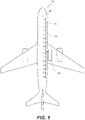
- FIG. 1 is a schematic illustration of one example of vehicle 190, which is an aircraft. However, other types of vehicles are also within the scope of this disclosure.
- Vehicle 190 comprises cabin 192, used by passengers and crew.
- Vehicle 190 also comprises ECS unit 194, used for controlling the environmental conditions within cabin 192.
- ECS unit 194 is used to treat air, e.g., recycled from cabin 192 and/or obtained from the external environment. Some examples of this air treatment include, but are not limited to, heating, cooling, filtering, adjusting humidity, and the like.
- ECS unit 194 is positioned away from cabin 192, e.g., in the wing areas of the aircraft, and is fluidically coupled with cabin 192 by duct system 196. This positioning of ECS unit 194 allows utilizing other components and systems of vehicle 190 (e.g., for power) and reducing the noise level within cabin 192 during operation of ECS unit 194.
- duct system 196 extends from ECS unit 194 to cabin 192.
- Duct system 196 also extends throughout cabin 192 to ensure the desired distribution of air within cabin 192.
- passengers can control this air distribution using individual vents connected to duct system 196, e.g., each passenger has a dedicated vent that controls the flow of air from duct system 196 to this passenger.
- duct system 196 comprises or, more specifically, is assembled using multiple individual ducts 100.
- Individual ducts 100 are interconnected to form duct system 196 and also connected to various other components, e.g., ECS unit 194, air vents, and the like. This modular approach helps with the installation of duct system 196.
- ECS unit 194 air vents, and the like.
- This modular approach helps with the installation of duct system 196.
- the same type of duct 100 can be used for different portions of duct system 196 and even for different vehicles.
- Ducts 100 are connected and supported by various structural components of vehicle 190.
- Ducts 100 are specifically designed to provide noise attenuation as the air flows through duct system 196 from ECS unit 194 to cabin 192.
- ducts 100 can also be referred to as noise-attenuating ducts.
- These noise attenuation characteristics are achieved by a specific structure of ducts 100.
- each duct comprises an exoskeleton structure and a sound-absorbing structure, disposed within the interior of the exoskeleton structure and conforming to the exoskeleton structure.
- the exoskeleton structure provides external mechanical support to the sound-absorbing structure, e.g., to maintain the tubular shape of the sound-absorbing structure.
- the sound-absorbing structure forms an enclosure for the air flowing through the duct and also provides the overall noise attenuation due to the specific design of the sound-absorbing structure.
- duct designs described herein provide one-piece, additively manufactured exoskeleton structures coupled to sound-absorbing structures (for insulation, noise attenuation / self-muffling).
- exoskeleton structures comprise built-in (integrated / monolithic) support brackets. These designs provide for average weight savings from about 5 kilograms to about 20 kilograms or, more specifically, from about 5 kilograms to about 10 kilograms per aircraft depending on the aircraft size, configuration, and design.
- the total assembly part count is reduced by at least 50% or at least 55% with these duct designs, e.g., by eliminating separate fasteners.
- approximately 30 to 50 work-hours are saved by these designs (enabled, in part, by additive manufacturing) and/or use of single-pass manufacturing and snap-on exoskeleton sleeve with integrated attachment features (e.g., push-in screws).
- moisture barriers have been moved from the internal position (in conventional ducts) to the external position (e.g., as external membrane 130), thereby improving the overall protection.
- duct 100 comprises exoskeleton structure 110 and sound-absorbing structure 120.
- Exoskeleton structure 110 is formed using additive manufacturing, which allows incorporating various features (described below) while maintaining a monolithic structure.
- Exoskeleton structure 110 comprises exoskeleton inner surface 112, having a tubular shape and defining exoskeleton interior 114.
- Exoskeleton structure 110 also comprises exoskeleton outer surface 111, opposite to exoskeleton inner surface 112.
- Sound-absorbing structure 120 is disposed within exoskeleton interior 114 and conforms to exoskeleton inner surface 112.
- Sound-absorbing structure 120 comprises sound-absorbing inner surface 122, which also has a tubular shape. Sound-absorbing inner surface 122 defines sound-absorbing interior 124. Sound-absorbing structure 120 also comprises sound-absorbing outer surface 121, opposite of sound-absorbing inner surface 122.
- Exoskeleton structure 110 defines and supports the cross-sectional shape of sound-absorbing structure 120.
- Some cross-sectional shape examples include, but are not limited to, a circular cross-section, an elliptical cross-section, a rectangular cross-section, a square cross-section, a triangular cross-section, or a hexagonal cross-section.
- sound-absorbing structure 120 does not need to be self-supporting, which allows using various new materials for sound-absorbing structure 120 and improving sound-absorbing characteristics of duct 100.
- sound-absorbing structure 120 may be formed from foams with higher porosity than conventional ducts.
- duct 100 also comprises external membrane 130 and/or internal membrane 140.
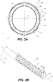
- FIG. 2A illustrates duct 100 with both external membrane 130 and internal membrane 140.
- sound-absorbing structure 120 can be fully enclosed by external membrane 130 and internal membrane 140 (e.g., sealed from all environments by external membrane 130 and internal membrane 140).
- external membrane 130 comprises external-membrane inner surface 132, also having a tubular shape and defining external-membrane interior 134.
- External membrane 130 also comprises external-membrane outer surface 131, opposite of external-membrane inner surface 132. When external membrane 130 is present, external-membrane inner surface 132 is in contact with the air flowing through duct 100.
- external-membrane inner surface 132 defines the interior of duct 100.
- External-membrane outer surface 131 contacts, at least in part, sound-absorbing structure 120.
- Internal membrane 140 comprises internal-membrane inner surface 142, also having a tubular shape and defining internal-membrane interior 144.
- Internal membrane 140 also comprises internal-membrane outer surface 141, opposite of internal-membrane inner surface 142. When internal membrane 140 is present, at least a portion of internal-membrane inner surface 142 contacts sound-absorbing structure 120. In some examples (further described below with reference to FIGS.
- an additional portion of internal-membrane inner surface 142 contacts or, more specifically, is sealed against external-membrane outer surface 131, e.g., to seal sound-absorbing structure 120 between external membrane 130 and internal membrane 140.
- Internal-membrane outer surface 141 contacts, at least in part, exoskeleton structure 110. In some examples, a portion of internal-membrane outer surface 141 is exposed, e.g., through the openings in exoskeleton structure 110.
- FIG. 2D illustrates another example, in which duct 100 does not have either external membrane 130 or internal membrane 140.
- sound-absorbing structure 120 directly interfaces exoskeleton structure 110.
- sound-absorbing inner surface 122 of sound-absorbing structure 120 is exposed to the air flowing within duct 100.
- sound-absorbing inner surface 122 forms the duct's interior. This example may be used to reduce the overall weight of duct 100, e.g., when additional insulation (e.g., from moisture) of sound-absorbing structure 120 is not needed.
- FIG. 2E illustrates yet another example in which duct 100 comprises external membrane 130 but not internal membrane 140.
- external membrane 130 is disposed between sound-absorbing structure 120 and exoskeleton structure 110. Sound-absorbing inner surface 122 remains exposed to the air flowing within duct 100 and forms the duct's interior.
- FIG. 2E illustrates another example, in which duct 100 comprises internal membrane 140 but not external membrane 130.
- sound-absorbing structure 120 directly interfaces exoskeleton structure 110.
- sound-absorbing inner surface 122 is protected from air flowing within duct 100. This example may help to reduce the friction to the air flowing within duct 100.
- sound-absorbing structure 120 directly interfaces exoskeleton inner surface 112 as, e.g., is shown in FIGS. 2D and 2E .
- one or more other components e.g., external membrane 130
- exoskeleton structure 110 provides mechanical support to sound-absorbing structure 120 and other components of duct 100 (e.g., external membrane 130 and/or internal membrane 140) when these components are present.
- exoskeleton structure 110 comprises a thermoplastic polymer, such as polyetherimide (PEI) and polyetherketoneketone (PEKK).
- Thermoplastic polymers can be used in additive manufacturing, which allows forming exoskeleton structure 110 having various shapes and features, which are described below in more detail.
- thermoplastic polymers can be welded together and formed into complex shapes using, e.g., injection molding.
- exoskeleton structure 110 comprises enclosed openings 116.
- Enclosed openings 116 are used to reduce the overall weight of exoskeleton structure 110 while providing sufficient support to sound-absorbing structure 120.
- enclosed openings 116 can be used to increase the flexibility (e.g., bendability) of exoskeleton structure 110 (and of the entire duct 100) as, e.g., is schematically shown in FIGS. 2G and 2H .
- exoskeleton structure 110 is configured to allow bending of duct 100 about any axes perpendicular to center axis 101.
- the area of enclosed openings 116 is greater than the area of exoskeleton inner surface 112. In more specific examples, the ratio of the area of enclosed openings 116 to the area of inner exoskeleton surface 112 is at least about 2, at least about 4, or even at least about 10. As noted above, this level of enclosed openings 116 ensures weight savings and bendability.
- enclosed openings 116 are evenly distributed throughout exoskeleton inner surface 112. The even distribution of enclosed openings 116 ensures the even mechanical support and other characteristics of exoskeleton structure 110. Enclosed openings 116 are separated by exoskeleton structure portions that form these enclosed openings 116. These exoskeleton structure portions provide the support to sound-absorbing structure 120.
- enclosed openings 116 have a rhombus shape. This shape allows minimizing the size of the exoskeleton structure portions, surrounding these enclosed openings 116 while providing uniform support to sound-absorbing structure 120.
- Other shapes of enclosed openings 116 e.g., round, square, hexagonal, and/or a combination thereof are also within the scope.
- the principal (largest) dimension of enclosed openings 116 is from 5 millimeters to 100 millimeters or, more specifically, from 10 millimeters to 50 millimeters such as between 20 millimeters to 40 millimeters.
- the diameter or, more generally, the principal cross-sectional dimension of sound-absorbing structure 120 is from 20 millimeters to 40 millimeters to 400 millimeters or, more specifically, from 50 millimeters to 300 millimeters such as from 100 millimeters to 200 millimeters.
- the length of sound-absorbing structure 120 is from 0.5 meters to 3 meters or, more specifically, from 0.75 meters to 2 meters such as from 1 meter to 1.5 meters.
- sound-absorbing structure 120 comprises an open-cell foam, such as melamine foam, polyimide foam, kevlar, and other like foams.
- the uncompressed thickness of sound-absorbing structure 120 can be from 5 millimeters to 30 millimeters or, more specifically, from 8 millimeters to 20 millimeters.
- duct 100 further comprises external membrane 130, disposed between exoskeleton structure 110 and sound-absorbing structure 120.
- external membrane 130 is in direct contact with exoskeleton inner surface 112 and/or sound-absorbing structure 120.
- External membrane 130 is used, e.g., to protect sound-absorbing structure 120 from the ambient environment. As a result of this protection, a larger variety of sound-absorbing materials can be used for sound-absorbing structure 120 as described above.
- external membrane 130 is formed from polyether ketone-ketone (PEKK) film, a polyether ether-ketone (PEEK) film, a metalized polyether ether-ketone (MPEEK) film, a polyvinyl fluoride (PVF), a non-flammable material pressure-sensitive tape, or a combination thereof (e.g., a first layer of PEKK film and a second layer of PEEK film).
- external membrane 130 comprises an adhesive (e.g., a heat-activated adhesive) on a non-metalized inner surface, which faces sound-absorbing structure 120.
- external membrane 130 is formed from a high-mass fabric, such as a woven material with high-mass resin. In the same or other examples, the thickness of external membrane 130 is from 0.005 millimeters to 1 millimeter or, more specifically, from 0.050 millimeters to 0.5 millimeters.
- duct 100 further comprises internal membrane 140, disposed within sound-absorbing interior 124.
- internal membrane 140 conforms to sound-absorbing inner surface 122 or, in more specific examples, directly contacts sound-absorbing inner surface 122 of sound-absorbing structure 120.
- Internal membrane 140 is used, e.g., to protect sound-absorbing structure 120 from the air flowing within through duct 100.
- the air may contain some moisture.
- internal membrane 140 provides a smooth interior surface, interfacing the air.
- internal membrane 140 is formed from polyether ketone-ketone (PEKK) film, a polyether ether ketone (PEEK) film, a metalized polyether ether-ketone (MPEEK) film, a polyvinyl fluoride (PVF), a non-flammable material pressure-sensitive tape, or a combination thereof (e.g., a first layer of PEKK film and a second layer of PEEK film).
- internal membrane 140 comprises an adhesive (e.g., a heat-activated adhesive) on a non-metalized inner surface, which faces sound-absorbing structure 120 or on a non-metalized outer surface facing exoskeleton structure 110.
- internal membrane 140 is formed from a high-mass fabric, such as a woven material with high-mass resin.
- the thickness of internal membrane 140 is from 0.005 millimeters to 1 millimeter or, more specifically, from 0.050 millimeters to 0.5 millimeters.
- external membrane 130 is sealed relative to internal membrane 140 thereby isolating sound-absorbing structure 120 from any environment.
- external membrane 130 and internal membrane 140 may be heat sealed (e.g., thermally welded), adhered, or otherwise sealed.
- the seal extends over the entire perimeter of sound-absorbing structure 120.
- duct 100 further comprises inner-membrane fastener 150.
- Inner-membrane fastener 150 protrudes through at least internal membrane 140 and supports internal membrane 140 relative to exoskeleton structure 110. This support of internal membrane 140 also supports sound-absorbing structure 120 relative to exoskeleton structure 110. As noted above, sound-absorbing structure 120 is disposed between internal membrane 140 and exoskeleton structure 110. In some examples, inner-membrane fastener 150 protrudes through sound-absorbing structure 120 and/or external membrane 130.
- inner-membrane fastener 150 is monolithic with exoskeleton structure 110.
- This fastener integration allows minimizing the number of parts needed for assembling duct 100.
- inner-membrane fastener 150 can be a push-pin inserted through exoskeleton structure 110.
- exoskeleton structure 110 is equipped with a locking mechanism for receiving and retaining a portion of the push-pin.
- exoskeleton structure 110 comprises snap fastener 160, monolithic with remaining parts of exoskeleton structure 110.
- Snap fastener 160 extends away from sound-absorbing structure 120 or, more specifically, from center axis 101 of duct 100.
- Snap fastener 160 is used for attaching and supporting duct 100 on an external structure, such as bracket 168 shown in FIG. 3B .
- bracket 168 shown in FIG. 3B .
- snap fastener 160 at least partially protrudes through an opening in bracket 168 and locks within this opening (e.g., using an interlocking feature).
- the integration of snap fastener 160 into exoskeleton structure 110 allows minimizing the number of parts needed for the overall duct assembly.
- exoskeleton structure 110 comprises axial limiter 170, monolithic with remaining parts of exoskeleton structure 110.
- Axial limiter 170 is used for limiting at least the axial movement of duct 100 (e.g., along center axis 101 of duct 100) relative to the external structure, such as bracket 168 shown in FIG. 3B .
- the integration of axial limiter 170 into exoskeleton structure 110 allows minimizing the number of parts needed for the overall duct assembly.
- exoskeleton structure 110 are enabled by additive manufacturing of exoskeleton structure 110.
- FIGS. 4A and 4B illustrate two examples of exoskeleton structure 110 formed by additive manufacturing. Specifically, the example in FIG.4A is similar to the one shown and described above with reference to FIGS. 2B and 3B .
- exoskeleton structure 110 comprises snap fasteners 160 and axial limiters 170 (monolithic with the rest of exoskeleton structure 110).
- Exoskeleton structure 110 also comprises enclosed openings 116 having a rhombus shape.
- FIG. 4B illustrates another example of exoskeleton structure 110 with a different type of snap fasteners 160 and a different type of enclosed openings 116.
- exoskeleton structure 110 in FIG. 4B is configured to support two sound-absorbing structures, extending parallel to each other.
- This exoskeleton structure 110 comprises two portions, which can be integrated together or be separated from each other.
- FIG. 4B also illustrates that one portion of exoskeleton structure 110 comprises duct split portions 119, extending away from center axis 101 of this portion. Duct split portions 119 allow diverting a portion of the airflow to various components, e.g., air vents, positioned along the length of duct 100.
- a portion of internal membrane 140 extends past sound-absorbing structure 120 forming connecting sleeve 145.
- Connecting sleeve 145 can be used for connecting to other components of the same ECS system, e.g., other ducts, air vents, and the like.
- This connection to component 500 is schematically shown in FIG. 5B .
- component 500 comprises annular protrusion 510 such that connecting sleeve 145 extends over and past this annular protrusion 510.
- the overall assembly also comprises annular clamp 520, which forces a portion of connecting sleeve 145 against component 500. As shown in FIG. 5B , this portion of connecting sleeve 145 extends past annular protrusion 510.
- a portion of external membrane 130 extending past sound-absorbing structure 120 can also form a connecting sleeve, similar to connecting sleeve 145 of internal membrane 140 described above. Furthermore, in some examples, this portion of external membrane 130 is sealed against a similar extending portion of internal membrane 140 as, e.g., is shown in FIG. 5A .
- FIG. 6 illustrates a process flowchart corresponding to method 600 of manufacturing duct 100.
- method 600 comprises (block 610) fabricating exoskeleton structure 110 using additive manufacturing.
- Exoskeleton structure 110 comprises exoskeleton inner surface 112 having a tubular shape and defining an exoskeleton interior 114.
- Additive manufacturing allows integrating various features into exoskeleton structure 110.
- these features and other parts of exoskeleton structure 110 can be monolithic (e.g., a single continuous piece without any joint interfaces).
- exoskeleton structure 110 comprises multiple pieces joined together with hinges and/or snaps to facilitate additive manufacturing and allow forming exoskeleton structure 110 that is particularly long.
- exoskeleton structure 110 is injection molded.
- exoskeleton structure 110 comprises two mating halves, e.g., separated along the plane containing the center axis of exoskeleton structure 110. These two halves are snapped together around sound-absorbing structure 120, which is formed in a sound-absorbing tubular shape before this snapping operation.
- method 600 comprises (block 615) sealing sound-absorbing structure 120 between external membrane 130 and internal membrane 140. This operation is performed, e.g., before forming sound-absorbing structure 120 into a sound-absorbing tubular shape as further described below.
- method 600 comprises (block 620) forming sound-absorbing structure 120 into a sound-absorbing tubular shape as, for example, is schematically shown in FIG. 7B .
- (block 620) forming sound-absorbing structure 120 into sound-absorbing tubular shape comprises (block 622) rolling a sound-absorbing sheet over a mandrel, having the sound-absorbing tubular shape.
- method 600 comprises (block 630) inserting sound-absorbing structure 120 into exoskeleton interior 114 such that sound-absorbing structure 120 conforms to exoskeleton inner surface 112 as, e.g., is schematically shown in FIG. 7C .
- a mandrel used to form the sound-absorbing tubular shape may remain inside sound-absorbing structure 120 during this operation.
- method 600 comprises (block 640) securing sound-absorbing structure 120 to exoskeleton structure 110 such that sound-absorbing structure 120 retains sound-absorbing tubular shape.
- inner-membrane fasteners 150 are used for this operation as, e.g., is schematically shown in FIG. 7D .
- methods, and systems described above are used on aircraft and, more generally, by the aerospace industry. Specifically, these methods and systems can be used during the fabrication of aircraft as well as during aircraft service and maintenance.
- method 900 includes specification and design 904 of aircraft 902 and material procurement 906.
- component, and subassembly manufacturing 908 and system integration 910 of aircraft 902 takes place.
- aircraft 902 goes through certification and delivery 912 to be placed in service 914.
- routine maintenance and service 916 which also includes modification, reconfiguration, refurbishment, and so on.
- each of the processes of method 900 is performed or carried out by a system integrator, a third party, and/or an operator, e.g., a customer.
- a system integrator includes without limitation any number of aircraft manufacturers and major-system subcontractors;
- a third party includes without limitation any number of vendors, subcontractors, and suppliers;
- an operator can be an airline, leasing company, military entity, service organization, and so on.
- aircraft 902 produced by method 900 includes airframe 918 with plurality of systems 920 and interior 922.
- the airframe 918 includes the wings of aircraft 902.
- systems 920 include one or more of propulsion system 924, electrical system 926, hydraulic system 928, and environmental system 930 or, more specifically, an ECS system comprising one or more sound-attenuating ducts described above. Any number of other systems can be included.
- Apparatus and methods presented herein can be employed during any one or more of the stages of method 900.
- components or subassemblies corresponding to manufacturing 908 are fabricated or manufactured like components or subassemblies produced while aircraft 902 is in service.
- one or more apparatus examples, method examples, or a combination thereof are utilized during manufacturing 908 and system integration 910, for example, by substantially expediting assembly of or reducing the cost of an aircraft 902.
- one or more apparatus examples, method examples, or a combination thereof are utilized while aircraft 902 is in service, for example, and without limitation, to maintenance and service 916.
Landscapes
- Engineering & Computer Science (AREA)
- General Engineering & Computer Science (AREA)
- Mechanical Engineering (AREA)
- Aviation & Aerospace Engineering (AREA)
- Physics & Mathematics (AREA)
- Manufacturing & Machinery (AREA)
- General Health & Medical Sciences (AREA)
- Pulmonology (AREA)
- Health & Medical Sciences (AREA)
- Chemical & Material Sciences (AREA)
- Combustion & Propulsion (AREA)
- Transportation (AREA)
- Acoustics & Sound (AREA)
- Multimedia (AREA)
- Thermal Sciences (AREA)
- Fluid Mechanics (AREA)
- Materials Engineering (AREA)
- Pipe Accessories (AREA)
- Duct Arrangements (AREA)
- Soundproofing, Sound Blocking, And Sound Damping (AREA)
Abstract
Description
- Many types of vehicles, such as aircraft, utilize environmental control systems to provide treated air to the passengers and/or cargo. For example, an environmental control system can supply air at a set temperature and/or a set flow rate to each passenger. Furthermore, an environmental control system can remove particles and other pollutants from the incoming air before supplying the clean air to the destination. An environmental control system typically includes various ducts to flow the air through the vehicle. However, the airflow within these ducts generates noise, which can be undesirable, especially when these ducts are positioned close to or inside the passenger cabins. Various special-purpose noise-attenuating components, such as zone mufflers, have been used to reduce the noise level. However, these additional special-purpose components increase the vehicle weight, occupy additional space, and raise the total system cost. Furthermore, supporting ducts within vehicles typically require additional components.
- What is needed are new types of ducts with in-situ noise attenuating capabilities that reduce and/or eliminate the need for additional noise attenuating components. In addition, it is desired to provide ducting having reduced weight, more compact size, and high levels of system modularity.
- Described herein are noise attenuating ducts and vehicles using these ducts for environmental control systems. Also provided are methods of manufacturing these ducts. A duct comprises an exoskeleton structure and a sound-absorbing structure, disposed within and conforming to the exoskeleton structure. The exoskeleton structure provides external mechanical support to the sound-absorbing structure thereby maintaining the tubular shape of the sound-absorbing structure. This external support does not interfere with the airflow inside the sound-absorbing structure. Furthermore, the external positioning of the exoskeleton structure provides an option for integrating various support mounting features into the exoskeleton structure. These features are used for the installation of the duct in a vehicle. This integration reduces the number of different components in a duct, reducing the overall complexity and installation time. Specifically, additive manufacturing of the exoskeleton structure allows this integration into one monolithic structure and providing various features and characteristics further described below. In some examples, the exoskeleton structure comprises a plurality of enclosed openings to reduce the weight of the exoskeleton structure and/or to provide additional flexibility to the duct.
-
-
FIG. 1 is a schematic illustration of an aircraft comprising an environmental control system that utilizes ducts for supplying treated air to various portions of the aircraft, in accordance with some examples. -
FIG. 2A is a schematic cross-sectional view of a duct, showing various internal components and features of the duct, in accordance with some examples. -
FIG. 2B is a schematic perspective view of a duct, showing various external components and features of the duct, in accordance with some examples. -
FIG. 2C is an exploded cross-sectional view of a duct, individually illustrating each component of the duct, in accordance with some examples. -
FIGS. 2D, 2E, and 2F are schematic cross-sectional views of a duct, showing various options for external and internal membranes, in accordance with some examples. -
FIGS. 2G and 2H are schematic top views of a duct before and after bending of the duct, in accordance with some examples. -
FIG. 3A is a schematic cross-sectional view of a duct illustrating inner-membrane fasteners, in accordance with some examples. -
FIG. 3B is a schematic perspective view of a duct portion showing snap fasteners and an axial limiter, in accordance with some examples. -
FIG. 4A is a schematic perspective view of an exoskeleton structure illustrating enclosed openings of the exoskeleton structure as well as snap fasteners and an axial limiter of the exoskeleton structure, in accordance with some examples. -
FIG. 4B is a schematic perspective view of another example of the exoskeleton structure, configured to provide support to two separate parallel sound-absorbing structures and forming a fluidic connection to one of these sound-absorbing structures through duct split portions. -
FIG. 5A is a schematic cross-sectional view of a duct illustrating a connecting sleeve formed by an internal membrane and extending past an exoskeleton structure, in accordance with some examples. -
FIG. 5B is a schematic cross-sectional view of a duct connected to another structure using a connecting sleeve, in accordance with some examples. -
FIG. 6 is a process flowchart corresponding to a method for fabricating a duct, in accordance with some examples. -
FIGS. 7A - 7D are various stages during the fabrication of a duct, in accordance with some examples. -
FIG. 8 is a process flowchart corresponding to a method for manufacturing and servicing the aircraft. -
FIG. 9 illustrates a block diagram of an example aircraft, in accordance with some examples. - In the following description, numerous specific details are outlined to provide a thorough understanding of the presented concepts. In some examples, the presented concepts are practiced without some or all of these specific details. In other examples, well-known process operations have not been described in detail to unnecessarily obscure the described concepts. While some concepts will be described in conjunction with the specific examples, it will be understood that these examples are not intended to be limiting.
- An environmental control system (ECS) can be used on a vehicle to control the temperature, humidity, and/or other environmental conditions of the vehicle interior, such as a passenger compartment, cargo compartment, and the like.
FIG. 1 is a schematic illustration of one example ofvehicle 190, which is an aircraft. However, other types of vehicles are also within the scope of this disclosure.Vehicle 190 comprisescabin 192, used by passengers and crew.Vehicle 190 also comprisesECS unit 194, used for controlling the environmental conditions withincabin 192. Specifically,ECS unit 194 is used to treat air, e.g., recycled fromcabin 192 and/or obtained from the external environment. Some examples of this air treatment include, but are not limited to, heating, cooling, filtering, adjusting humidity, and the like. In some examples,ECS unit 194 is positioned away fromcabin 192, e.g., in the wing areas of the aircraft, and is fluidically coupled withcabin 192 byduct system 196. This positioning ofECS unit 194 allows utilizing other components and systems of vehicle 190 (e.g., for power) and reducing the noise level withincabin 192 during operation ofECS unit 194. - Referring to
FIG. 1 ,duct system 196 extends fromECS unit 194 tocabin 192.Duct system 196 also extends throughoutcabin 192 to ensure the desired distribution of air withincabin 192. For example, passengers can control this air distribution using individual vents connected toduct system 196, e.g., each passenger has a dedicated vent that controls the flow of air fromduct system 196 to this passenger. - In some examples,
duct system 196 comprises or, more specifically, is assembled using multipleindividual ducts 100.Individual ducts 100 are interconnected to formduct system 196 and also connected to various other components, e.g.,ECS unit 194, air vents, and the like. This modular approach helps with the installation ofduct system 196. Furthermore, the same type ofduct 100 can be used for different portions ofduct system 196 and even for different vehicles.Ducts 100 are connected and supported by various structural components ofvehicle 190. -
Ducts 100 are specifically designed to provide noise attenuation as the air flows throughduct system 196 fromECS unit 194 tocabin 192. As such,ducts 100 can also be referred to as noise-attenuating ducts. These noise attenuation characteristics are achieved by a specific structure ofducts 100. For example, each duct comprises an exoskeleton structure and a sound-absorbing structure, disposed within the interior of the exoskeleton structure and conforming to the exoskeleton structure. The exoskeleton structure provides external mechanical support to the sound-absorbing structure, e.g., to maintain the tubular shape of the sound-absorbing structure. The sound-absorbing structure forms an enclosure for the air flowing through the duct and also provides the overall noise attenuation due to the specific design of the sound-absorbing structure. - Overall, duct designs described herein provide one-piece, additively manufactured exoskeleton structures coupled to sound-absorbing structures (for insulation, noise attenuation / self-muffling). In some examples, exoskeleton structures comprise built-in (integrated / monolithic) support brackets. These designs provide for average weight savings from about 5 kilograms to about 20 kilograms or, more specifically, from about 5 kilograms to about 10 kilograms per aircraft depending on the aircraft size, configuration, and design. In addition, the total assembly part count is reduced by at least 50% or at least 55% with these duct designs, e.g., by eliminating separate fasteners. In some examples, approximately 30 to 50 work-hours are saved by these designs (enabled, in part, by additive manufacturing) and/or use of single-pass manufacturing and snap-on exoskeleton sleeve with integrated attachment features (e.g., push-in screws). Furthermore, moisture barriers have been moved from the internal position (in conventional ducts) to the external position (e.g., as external membrane 130), thereby improving the overall protection.
- Referring to
FIGS. 2A, 2B , and2C ,duct 100 comprisesexoskeleton structure 110 and sound-absorbingstructure 120.Exoskeleton structure 110 is formed using additive manufacturing, which allows incorporating various features (described below) while maintaining a monolithic structure.Exoskeleton structure 110 comprises exoskeletoninner surface 112, having a tubular shape and definingexoskeleton interior 114.Exoskeleton structure 110 also comprises exoskeletonouter surface 111, opposite to exoskeletoninner surface 112. - Sound-absorbing
structure 120 is disposed withinexoskeleton interior 114 and conforms to exoskeletoninner surface 112. Sound-absorbingstructure 120 comprises sound-absorbinginner surface 122, which also has a tubular shape. Sound-absorbinginner surface 122 defines sound-absorbinginterior 124. Sound-absorbingstructure 120 also comprises sound-absorbingouter surface 121, opposite of sound-absorbinginner surface 122. -
Exoskeleton structure 110 defines and supports the cross-sectional shape of sound-absorbingstructure 120. Some cross-sectional shape examples include, but are not limited to, a circular cross-section, an elliptical cross-section, a rectangular cross-section, a square cross-section, a triangular cross-section, or a hexagonal cross-section. As such, sound-absorbingstructure 120 does not need to be self-supporting, which allows using various new materials for sound-absorbingstructure 120 and improving sound-absorbing characteristics ofduct 100. For example, sound-absorbingstructure 120 may be formed from foams with higher porosity than conventional ducts. - In some examples,
duct 100 also comprisesexternal membrane 130 and/orinternal membrane 140. For example,FIG. 2A illustratesduct 100 with bothexternal membrane 130 andinternal membrane 140. In this example, sound-absorbingstructure 120 can be fully enclosed byexternal membrane 130 and internal membrane 140 (e.g., sealed from all environments byexternal membrane 130 and internal membrane 140). Referring toFIG. 2B and2C ,external membrane 130 comprises external-membraneinner surface 132, also having a tubular shape and defining external-membrane interior 134.External membrane 130 also comprises external-membraneouter surface 131, opposite of external-membraneinner surface 132. Whenexternal membrane 130 is present, external-membraneinner surface 132 is in contact with the air flowing throughduct 100. In other words, external-membraneinner surface 132 defines the interior ofduct 100. External-membraneouter surface 131 contacts, at least in part, sound-absorbingstructure 120.Internal membrane 140 comprises internal-membraneinner surface 142, also having a tubular shape and defining internal-membrane interior 144.Internal membrane 140 also comprises internal-membraneouter surface 141, opposite of internal-membraneinner surface 142. Wheninternal membrane 140 is present, at least a portion of internal-membraneinner surface 142 contacts sound-absorbingstructure 120. In some examples (further described below with reference toFIGS. 5A and 5B ), an additional portion of internal-membraneinner surface 142 contacts or, more specifically, is sealed against external-membraneouter surface 131, e.g., to seal sound-absorbingstructure 120 betweenexternal membrane 130 andinternal membrane 140. Internal-membraneouter surface 141 contacts, at least in part,exoskeleton structure 110. In some examples, a portion of internal-membraneouter surface 141 is exposed, e.g., through the openings inexoskeleton structure 110. -
FIG. 2D illustrates another example, in whichduct 100 does not have eitherexternal membrane 130 orinternal membrane 140. In this example, sound-absorbingstructure 120 directly interfacesexoskeleton structure 110. Furthermore, sound-absorbinginner surface 122 of sound-absorbingstructure 120 is exposed to the air flowing withinduct 100. In other words, sound-absorbinginner surface 122 forms the duct's interior. This example may be used to reduce the overall weight ofduct 100, e.g., when additional insulation (e.g., from moisture) of sound-absorbingstructure 120 is not needed. -
FIG. 2E illustrates yet another example in whichduct 100 comprisesexternal membrane 130 but notinternal membrane 140. In this example,external membrane 130 is disposed between sound-absorbingstructure 120 andexoskeleton structure 110. Sound-absorbinginner surface 122 remains exposed to the air flowing withinduct 100 and forms the duct's interior. - Finally,
FIG. 2E illustrates another example, in whichduct 100 comprisesinternal membrane 140 but notexternal membrane 130. In this example, sound-absorbingstructure 120 directly interfacesexoskeleton structure 110. However, sound-absorbinginner surface 122 is protected from air flowing withinduct 100. This example may help to reduce the friction to the air flowing withinduct 100. - Overall, in some examples, sound-absorbing
structure 120 directly interfaces exoskeletoninner surface 112 as, e.g., is shown inFIGS. 2D and 2E . Alternatively, one or more other components (e.g., external membrane 130) are disposed betweenexoskeleton structure 110 and sound-absorbingstructure 120 as, e.g., is shown inFIGS. 2A and2E . In either case,exoskeleton structure 110 provides mechanical support to sound-absorbingstructure 120 and other components of duct 100 (e.g.,external membrane 130 and/or internal membrane 140) when these components are present. - In some examples,
exoskeleton structure 110 comprises a thermoplastic polymer, such as polyetherimide (PEI) and polyetherketoneketone (PEKK). Thermoplastic polymers can be used in additive manufacturing, which allows formingexoskeleton structure 110 having various shapes and features, which are described below in more detail. Furthermore, thermoplastic polymers can be welded together and formed into complex shapes using, e.g., injection molding. - Referring to
FIGS. 2A and 2B , in some examples,exoskeleton structure 110 comprisesenclosed openings 116.Enclosed openings 116 are used to reduce the overall weight ofexoskeleton structure 110 while providing sufficient support to sound-absorbingstructure 120. Furthermore,enclosed openings 116 can be used to increase the flexibility (e.g., bendability) of exoskeleton structure 110 (and of the entire duct 100) as, e.g., is schematically shown inFIGS. 2G and 2H . For example,exoskeleton structure 110 is configured to allow bending ofduct 100 about any axes perpendicular tocenter axis 101. - In some examples, the area of
enclosed openings 116 is greater than the area of exoskeletoninner surface 112. In more specific examples, the ratio of the area ofenclosed openings 116 to the area ofinner exoskeleton surface 112 is at least about 2, at least about 4, or even at least about 10. As noted above, this level ofenclosed openings 116 ensures weight savings and bendability. - In some examples,
enclosed openings 116 are evenly distributed throughout exoskeletoninner surface 112. The even distribution ofenclosed openings 116 ensures the even mechanical support and other characteristics ofexoskeleton structure 110.Enclosed openings 116 are separated by exoskeleton structure portions that form theseenclosed openings 116. These exoskeleton structure portions provide the support to sound-absorbingstructure 120. - In some examples, at least some of
enclosed openings 116 have a rhombus shape. This shape allows minimizing the size of the exoskeleton structure portions, surrounding theseenclosed openings 116 while providing uniform support to sound-absorbingstructure 120. Other shapes of enclosed openings 116 (e.g., round, square, hexagonal, and/or a combination thereof) are also within the scope. In some examples, the principal (largest) dimension ofenclosed openings 116 is from 5 millimeters to 100 millimeters or, more specifically, from 10 millimeters to 50 millimeters such as between 20 millimeters to 40 millimeters. - In the same or other examples, the diameter or, more generally, the principal cross-sectional dimension of sound-absorbing
structure 120 is from 20 millimeters to 40 millimeters to 400 millimeters or, more specifically, from 50 millimeters to 300 millimeters such as from 100 millimeters to 200 millimeters. In the same or other examples, the length of sound-absorbingstructure 120 is from 0.5 meters to 3 meters or, more specifically, from 0.75 meters to 2 meters such as from 1 meter to 1.5 meters. - In some examples, sound-absorbing
structure 120 comprises an open-cell foam, such as melamine foam, polyimide foam, kevlar, and other like foams. The uncompressed thickness of sound-absorbingstructure 120 can be from 5 millimeters to 30 millimeters or, more specifically, from 8 millimeters to 20 millimeters. - As noted above, in some examples,
duct 100 further comprisesexternal membrane 130, disposed betweenexoskeleton structure 110 and sound-absorbingstructure 120. For example,external membrane 130 is in direct contact with exoskeletoninner surface 112 and/or sound-absorbingstructure 120.External membrane 130 is used, e.g., to protect sound-absorbingstructure 120 from the ambient environment. As a result of this protection, a larger variety of sound-absorbing materials can be used for sound-absorbingstructure 120 as described above. - In some examples,
external membrane 130 is formed from polyether ketone-ketone (PEKK) film, a polyether ether-ketone (PEEK) film, a metalized polyether ether-ketone (MPEEK) film, a polyvinyl fluoride (PVF), a non-flammable material pressure-sensitive tape, or a combination thereof (e.g., a first layer of PEKK film and a second layer of PEEK film). In some examples,external membrane 130 comprises an adhesive (e.g., a heat-activated adhesive) on a non-metalized inner surface, which faces sound-absorbingstructure 120. In some examples,external membrane 130 is formed from a high-mass fabric, such as a woven material with high-mass resin. In the same or other examples, the thickness ofexternal membrane 130 is from 0.005 millimeters to 1 millimeter or, more specifically, from 0.050 millimeters to 0.5 millimeters. - In some examples,
duct 100 further comprisesinternal membrane 140, disposed within sound-absorbinginterior 124. For example,internal membrane 140 conforms to sound-absorbinginner surface 122 or, in more specific examples, directly contacts sound-absorbinginner surface 122 of sound-absorbingstructure 120.Internal membrane 140 is used, e.g., to protect sound-absorbingstructure 120 from the air flowing within throughduct 100. For example, the air may contain some moisture. Furthermore,internal membrane 140 provides a smooth interior surface, interfacing the air. - In some examples,
internal membrane 140 is formed from polyether ketone-ketone (PEKK) film, a polyether ether ketone (PEEK) film, a metalized polyether ether-ketone (MPEEK) film, a polyvinyl fluoride (PVF), a non-flammable material pressure-sensitive tape, or a combination thereof (e.g., a first layer of PEKK film and a second layer of PEEK film). In some examples,internal membrane 140 comprises an adhesive (e.g., a heat-activated adhesive) on a non-metalized inner surface, which faces sound-absorbingstructure 120 or on a non-metalized outer surface facingexoskeleton structure 110. In some examples,internal membrane 140 is formed from a high-mass fabric, such as a woven material with high-mass resin. In the same or other examples, the thickness ofinternal membrane 140 is from 0.005 millimeters to 1 millimeter or, more specifically, from 0.050 millimeters to 0.5 millimeters. - In some examples,
external membrane 130 is sealed relative tointernal membrane 140 thereby isolating sound-absorbingstructure 120 from any environment. For example,external membrane 130 andinternal membrane 140 may be heat sealed (e.g., thermally welded), adhered, or otherwise sealed. In more specific examples, the seal extends over the entire perimeter of sound-absorbingstructure 120. - Referring to
FIG. 3A , in some examples,duct 100 further comprises inner-membrane fastener 150. Inner-membrane fastener 150 protrudes through at leastinternal membrane 140 and supportsinternal membrane 140 relative toexoskeleton structure 110. This support ofinternal membrane 140 also supports sound-absorbingstructure 120 relative toexoskeleton structure 110. As noted above, sound-absorbingstructure 120 is disposed betweeninternal membrane 140 andexoskeleton structure 110. In some examples, inner-membrane fastener 150 protrudes through sound-absorbingstructure 120 and/orexternal membrane 130. - Referring to
FIG. 3A , in some examples, at least a portion of inner-membrane fastener 150 is monolithic withexoskeleton structure 110. This fastener integration allows minimizing the number of parts needed for assemblingduct 100. For example, inner-membrane fastener 150 can be a push-pin inserted throughexoskeleton structure 110. In these examples,exoskeleton structure 110 is equipped with a locking mechanism for receiving and retaining a portion of the push-pin. - Referring to
FIG. 3B , in some examples,exoskeleton structure 110 comprisessnap fastener 160, monolithic with remaining parts ofexoskeleton structure 110.Snap fastener 160 extends away from sound-absorbingstructure 120 or, more specifically, fromcenter axis 101 ofduct 100.Snap fastener 160 is used for attaching and supportingduct 100 on an external structure, such asbracket 168 shown inFIG. 3B . For example,snap fastener 160 at least partially protrudes through an opening inbracket 168 and locks within this opening (e.g., using an interlocking feature). The integration ofsnap fastener 160 intoexoskeleton structure 110 allows minimizing the number of parts needed for the overall duct assembly. - Referring to
FIG. 3B , in some examples,exoskeleton structure 110 comprisesaxial limiter 170, monolithic with remaining parts ofexoskeleton structure 110.Axial limiter 170 is used for limiting at least the axial movement of duct 100 (e.g., alongcenter axis 101 of duct 100) relative to the external structure, such asbracket 168 shown inFIG. 3B . The integration ofaxial limiter 170 intoexoskeleton structure 110 allows minimizing the number of parts needed for the overall duct assembly. - These and other aspects of
exoskeleton structure 110 are enabled by additive manufacturing ofexoskeleton structure 110.FIGS. 4A and 4B illustrate two examples ofexoskeleton structure 110 formed by additive manufacturing. Specifically, the example inFIG.4A is similar to the one shown and described above with reference toFIGS. 2B and3B . In this example,exoskeleton structure 110 comprisessnap fasteners 160 and axial limiters 170 (monolithic with the rest of exoskeleton structure 110).Exoskeleton structure 110 also comprisesenclosed openings 116 having a rhombus shape. -
FIG. 4B illustrates another example ofexoskeleton structure 110 with a different type ofsnap fasteners 160 and a different type ofenclosed openings 116. Specifically,exoskeleton structure 110 inFIG. 4B is configured to support two sound-absorbing structures, extending parallel to each other. Thisexoskeleton structure 110 comprises two portions, which can be integrated together or be separated from each other.FIG. 4B also illustrates that one portion ofexoskeleton structure 110 comprises duct splitportions 119, extending away fromcenter axis 101 of this portion. Duct splitportions 119 allow diverting a portion of the airflow to various components, e.g., air vents, positioned along the length ofduct 100. - Referring to
FIG. 5A , in some examples, a portion ofinternal membrane 140 extends past sound-absorbingstructure 120 forming connectingsleeve 145.Connecting sleeve 145 can be used for connecting to other components of the same ECS system, e.g., other ducts, air vents, and the like. This connection tocomponent 500 is schematically shown inFIG. 5B . For example,component 500 comprisesannular protrusion 510 such that connectingsleeve 145 extends over and past thisannular protrusion 510. The overall assembly also comprisesannular clamp 520, which forces a portion of connectingsleeve 145 againstcomponent 500. As shown inFIG. 5B , this portion of connectingsleeve 145 extends pastannular protrusion 510. - In some examples, a portion of
external membrane 130 extending past sound-absorbingstructure 120. This portion can also form a connecting sleeve, similar to connectingsleeve 145 ofinternal membrane 140 described above. Furthermore, in some examples, this portion ofexternal membrane 130 is sealed against a similar extending portion ofinternal membrane 140 as, e.g., is shown inFIG. 5A . -
FIG. 6 illustrates a process flowchart corresponding tomethod 600 ofmanufacturing duct 100. Various examples ofduct 100 are described above. In some examples,method 600 comprises (block 610) fabricatingexoskeleton structure 110 using additive manufacturing.Exoskeleton structure 110 comprises exoskeletoninner surface 112 having a tubular shape and defining anexoskeleton interior 114. Additive manufacturing allows integrating various features intoexoskeleton structure 110. For example, these features and other parts ofexoskeleton structure 110 can be monolithic (e.g., a single continuous piece without any joint interfaces). Alternately,exoskeleton structure 110 comprises multiple pieces joined together with hinges and/or snaps to facilitate additive manufacturing and allow formingexoskeleton structure 110 that is particularly long. - Alternatively,
exoskeleton structure 110 is injection molded. For example,exoskeleton structure 110 comprises two mating halves, e.g., separated along the plane containing the center axis ofexoskeleton structure 110. These two halves are snapped together around sound-absorbingstructure 120, which is formed in a sound-absorbing tubular shape before this snapping operation. - In some examples,
method 600 comprises (block 615) sealing sound-absorbingstructure 120 betweenexternal membrane 130 andinternal membrane 140. This operation is performed, e.g., before forming sound-absorbingstructure 120 into a sound-absorbing tubular shape as further described below. A sub-assembly formed during this operation and comprising sound-absorbingstructure 120, sealed betweenexternal membrane 130 andinternal membrane 140, is shown inFIG. 7A . In some examples, the subassembly is substantially planar upon completing this operation. - In some examples,
method 600 comprises (block 620) forming sound-absorbingstructure 120 into a sound-absorbing tubular shape as, for example, is schematically shown inFIG. 7B . In more specific examples, (block 620) forming sound-absorbingstructure 120 into sound-absorbing tubular shape comprises (block 622) rolling a sound-absorbing sheet over a mandrel, having the sound-absorbing tubular shape. - In some examples,
method 600 comprises (block 630) inserting sound-absorbingstructure 120 into exoskeleton interior 114 such that sound-absorbingstructure 120 conforms to exoskeletoninner surface 112 as, e.g., is schematically shown inFIG. 7C . In more specific examples, a mandrel used to form the sound-absorbing tubular shape may remain inside sound-absorbingstructure 120 during this operation. - In some examples,
method 600 comprises (block 640) securing sound-absorbingstructure 120 toexoskeleton structure 110 such that sound-absorbingstructure 120 retains sound-absorbing tubular shape. For example, inner-membrane fasteners 150 are used for this operation as, e.g., is schematically shown inFIG. 7D . - In some examples, methods, and systems described above are used on aircraft and, more generally, by the aerospace industry. Specifically, these methods and systems can be used during the fabrication of aircraft as well as during aircraft service and maintenance.
- Accordingly, the apparatus and methods described above are applicable for aircraft manufacturing and
service method 900 as shown inFIG. 8 and foraircraft 902 as shown inFIG. 9 . During pre-production,method 900 includes specification anddesign 904 ofaircraft 902 andmaterial procurement 906. During production, component, andsubassembly manufacturing 908 andsystem integration 910 ofaircraft 902 takes place. Thereafter,aircraft 902 goes through certification anddelivery 912 to be placed inservice 914. While in service by a customer,aircraft 902 is scheduled for routine maintenance andservice 916, which also includes modification, reconfiguration, refurbishment, and so on. - In some examples, each of the processes of
method 900 is performed or carried out by a system integrator, a third party, and/or an operator, e.g., a customer. For this dECSription, a system integrator includes without limitation any number of aircraft manufacturers and major-system subcontractors; a third party includes without limitation any number of vendors, subcontractors, and suppliers; and an operator can be an airline, leasing company, military entity, service organization, and so on. - As shown in
FIG. 9 ,aircraft 902 produced bymethod 900 includesairframe 918 with plurality ofsystems 920 and interior 922. Theairframe 918 includes the wings ofaircraft 902. Examples ofsystems 920 include one or more ofpropulsion system 924,electrical system 926,hydraulic system 928, andenvironmental system 930 or, more specifically, an ECS system comprising one or more sound-attenuating ducts described above. Any number of other systems can be included. - Apparatus and methods presented herein can be employed during any one or more of the stages of
method 900. For example, components or subassemblies corresponding to manufacturing 908 are fabricated or manufactured like components or subassemblies produced whileaircraft 902 is in service. Also, one or more apparatus examples, method examples, or a combination thereof are utilized duringmanufacturing 908 andsystem integration 910, for example, by substantially expediting assembly of or reducing the cost of anaircraft 902. Similarly, one or more apparatus examples, method examples, or a combination thereof are utilized whileaircraft 902 is in service, for example, and without limitation, to maintenance andservice 916. - Further, the description includes examples according to the following clauses:
-
Clause 1. A duct comprising:- an exoskeleton structure, formed using additive manufacturing and comprising an exoskeleton inner surface, the exoskeleton inner surface having a tubular shape and defining an exoskeleton interior; and
- a sound-absorbing structure, disposed within the exoskeleton interior and conforming to the exoskeleton inner surface, the sound-absorbing structure comprising a sound-absorbing inner surface defining a sound-absorbing interior.
- Clause 2. The duct of
clause 1, further comprising an external membrane, disposed between the exoskeleton structure and the sound-absorbing structure such that the external membrane is in direct contact with the exoskeleton inner surface. - Clause 3. The duct of clause 2, wherein the external membrane is in direct contact with the exoskeleton structure.
- Clause 4. The duct of
clause 1, further comprising an internal membrane, disposed within the sound-absorbing interior and conforming to the sound-absorbing inner surface. - Clause 5. The duct of clause 4, further comprising an external membrane, disposed between the exoskeleton structure and the sound-absorbing structure such that the external membrane is in direct contact with the exoskeleton inner surface.
- Clause 6. The duct of clause 5, wherein the external membrane is sealed relative to the internal membrane thereby isolating the sound-absorbing structure from environment.
- Clause 7. The duct of clause 6, wherein a portion of the internal membrane extends past the sound-absorbing structure forming a connecting sleeve.
- Clause 8. The duct of clause 5, wherein at least one of the internal membrane or the external membrane comprises a polyether ketone-ketone (PEKK) film, a polyether ether-ketone (PEEK) film, a polyvinyl fluoride (PVF), a non-flammable material pressure-sensitive tape, or a combination thereof.
- Clause 9. The duct of clause 5, further comprising an inner-membrane fastener, wherein:
- the inner-membrane fastener protrudes through the internal membrane and the sound-absorbing structure; and
- the inner-membrane fastener supports the internal membrane and the sound-absorbing structure relative to the exoskeleton structure.
- Clause 10. The duct of clause 9, wherein at least a portion of the inner-membrane fastener is monolithic with the exoskeleton structure.
- Clause 11. The duct of clause 9, further comprising an external membrane, wherein:
- the inner-membrane fastener further protrudes through the external membrane; and
- the inner-membrane fastener supports the external membrane relative to the exoskeleton structure.
- Clause 12. The duct of any one of clauses 1-11, wherein the exoskeleton structure comprises a thermoplastic polymer.
- Clause 13. The duct of any one of clauses 1-12, wherein the exoskeleton structure comprises a plurality of enclosed openings, evenly distributed around the inner exoskeleton surface.
- Clause 14. The duct of clause 13, wherein at least some openings of the plurality of enclosed openings have a rhombus shape.
- Clause 15. The duct of clause 13, wherein an area of the plurality of enclosed openings is greater than an area of the inner exoskeleton surface.
- Clause 16. The duct of clause 13, wherein an area of the plurality of enclosed openings is at least twice greater than an area of the inner exoskeleton surface.
- Clause 17. The duct of any one of clauses 1-16, wherein the exoskeleton structure comprises a snap fastener, monolithic with remaining parts of the exoskeleton structure and extending away from the sound-absorbing structure, the snap fastener being used for attaching and supporting the duct on an external structure.
- Clause 18. The duct of clause 17, wherein the exoskeleton structure comprises an axial limiter, monolithic with remaining parts of the exoskeleton structure and used for limiting at least an axial movement of the duct relative to the external structure.
- Clause 19. The duct of any one of clauses 1-18, wherein:
- the tubular shape is defined by a center axis of the duct;
- the exoskeleton structure is configured to retain a cross-section of the tubular shape, perpendicular to the center axis; and
- the exoskeleton structure is further configured to provide bending of the duct about any axes perpendicular to the center axis.
- Clause 20. The duct of any one of clause 1-19, wherein the tubular shape has at least one of a circular cross-section, an elliptical cross-section, a rectangular cross-section, a square cross-section, a triangular cross-section, or a hexagonal cross-section.
- Clause 21. The duct of any one of clauses 1-20, wherein:
- the tubular shape is defined by a center axis of the duct; and
- the exoskeleton structure comprises a duct split portion, extending away from the center axis.
- Clause 22. The duct of any one of clauses 1-21, wherein the sound-absorbing structure comprises melamine foam.
- Clause 23. A vehicle comprising:
an environmental control system comprising a duct, wherein the duct comprises:- an exoskeleton structure, formed using additive manufacturing and comprising an exoskeleton inner surface, the exoskeleton inner surface having a tubular shape and defining an exoskeleton interior; and
- a sound-absorbing structure, disposed within the exoskeleton interior and conforming to the exoskeleton inner surface, the sound-absorbing structure comprising a sound-absorbing inner surface defining a sound-absorbing interior.
- Clause 24. The vehicle of clause 23, wherein the vehicle is an aircraft.
- Clause 25. A method of manufacturing a duct, the method comprising:
- fabricating an exoskeleton structure using additive manufacturing, the exoskeleton structure comprising an exoskeleton inner surface having an exoskeleton tubular shape and defining an exoskeleton interior;
- forming a sound-absorbing structure into a sound-absorbing tubular shape, complimentary to the exoskeleton tubular shape;
- inserting the sound-absorbing structure into the exoskeleton interior such that sound-absorbing structure conforms to the exoskeleton inner surface; and
- securing the sound-absorbing structure to the exoskeleton structure such that the sound-absorbing structure retains the sound-absorbing tubular shape.
- Clause 26. The method of clause 25, wherein forming the sound-absorbing structure into the sound-absorbing tubular shape comprising rolling a sound-absorbing sheet over a mandrel, having the sound-absorbing tubular shape.
- Clause 27. The method of clause 25, further comprising, before forming the sound-absorbing structure into the sound-absorbing tubular shape, sealing the sound-absorbing structure between an external membrane and an internal membrane.
- Although the foregoing concepts have been dECSribed in some detail for purposes of clarity of understanding, it will be apparent that certain changes and modifications may be practiced within the scope of the appended clauses. It should be noted that there are many alternative ways of implementing the processes, systems, and apparatus. Accordingly, the present examples are to be considered illustrative and not restrictive.
Claims (15)
- A duct (100) comprising:an exoskeleton structure (110), formed using additive manufacturing and comprising an exoskeleton inner surface (112), the exoskeleton inner surface (112) having a tubular shape and defining an exoskeleton interior (114); anda sound-absorbing structure (120), disposed within the exoskeleton interior (114) and conforming to the exoskeleton inner surface (112), the sound-absorbing structure (120) comprising a sound-absorbing inner surface (122) defining a sound-absorbing interior (124).
- The duct (100) of claim 1, further comprising an external membrane (130), disposed between the exoskeleton structure (110) and the sound-absorbing structure (120) such that the external membrane (130) is in direct contact with the exoskeleton inner surface (112).
- The duct (100) of claim 2, wherein the external membrane (130) is in direct contact with the exoskeleton structure (110).
- The duct (100) of any of claims 1 to 3, further comprising an internal membrane (140), disposed within the sound-absorbing interior (124) and conforming to the sound-absorbing inner surface (122).
- The duct (100) of claim 4, further comprising an external membrane (130), disposed between the exoskeleton structure (110) and the sound-absorbing structure (120) such that the external membrane (130) is in direct contact with the exoskeleton inner surface (112).
- The duct (100) of claim 4, further comprising an external membrane (130), disposed between the exoskeleton structure (110) and the sound-absorbing structure (120) such that the external membrane (130) is in direct contact with the exoskeleton inner surface (112), wherein the external membrane (130) is sealed relative to the internal membrane (140) thereby isolating the sound-absorbing structure (120) from environment.
- The duct (100) of claim 5, wherein at least one of the internal membrane (140) or the external membrane (130) comprises a polyether ketone-ketone (PEKK) film, a polyether ether-ketone (PEEK) film, a polyvinyl fluoride (PVF), a non-flammable material pressure-sensitive tape, or a combination thereof.
- The duct (100) of claim 5, further comprising an inner-membrane fastener (150), wherein:the inner-membrane fastener (150) protrudes through the internal membrane (140) and the sound-absorbing structure (120); andthe inner-membrane fastener (150) supports the internal membrane (140) and the sound-absorbing structure (120) relative to the exoskeleton structure (110).
- The duct (100) of claim 8, further comprising an external membrane (130), wherein:the inner-membrane fastener (150) further protrudes through the external membrane (130); andthe inner-membrane fastener (150) supports the external membrane (130) relative to the exoskeleton structure (110).
- The duct (100) of any one of claims 1 to 9, wherein the exoskeleton structure (110) comprises a plurality of enclosed openings (116), evenly distributed around the inner exoskeleton surface (112).
- The duct (100) of claim 10, wherein an area of the plurality of enclosed openings (116) is greater than an area of the inner exoskeleton surface (112) at least some openings of the plurality of enclosed openings (116) have a rhombus shape.
- The duct (100) of any of claims 1 to 11, wherein the exoskeleton structure (110) comprises a snap fastener (160), monolithic with remaining parts of the exoskeleton structure (110) and extending away from the sound-absorbing structure (120), the snap fastener (160) being used for attaching and supporting the duct (100) on an external structure.
- A vehicle (190) comprising:
an environmental control system comprising a duct (100), wherein the duct (100) comprises:an exoskeleton structure (110), formed using additive manufacturing and comprising an exoskeleton inner surface (112), the exoskeleton inner surface (112) having a tubular shape and defining an exoskeleton interior (114); anda sound-absorbing structure (120), disposed within the exoskeleton interior (114) and conforming to the exoskeleton inner surface (112), the sound-absorbing structure (120) comprising a sound-absorbing inner surface (122) defining a sound-absorbing interior (124). - The vehicle (190) of claim 13, wherein the vehicle (190) is an aircraft.
- A method (600) of manufacturing a duct (100), the method (600) comprising:fabricating an exoskeleton structure (110) using additive manufacturing, the exoskeleton structure (110) comprising an exoskeleton inner surface (112) having an exoskeleton tubular shape and defining an exoskeleton interior (114);forming a sound-absorbing structure (120) into a sound-absorbing tubular shape, complimentary to the exoskeleton tubular shape;inserting the sound-absorbing structure (120) into the exoskeleton interior (114) such that sound-absorbing structure (120) conforms to the exoskeleton inner surface (112); andsecuring the sound-absorbing structure (120) to the exoskeleton structure (110) such that the sound-absorbing structure (120) retains the sound-absorbing tubular shape.
Applications Claiming Priority (1)
| Application Number | Priority Date | Filing Date | Title |
|---|---|---|---|
| US17/373,453 US12013071B2 (en) | 2021-07-12 | 2021-07-12 | Ducts comprising exoskeleton and sound-absorbing structures and vehicles using such ducts |
Publications (1)
| Publication Number | Publication Date |
|---|---|
| EP4119371A1 true EP4119371A1 (en) | 2023-01-18 |
Family
ID=81975285
Family Applications (1)
| Application Number | Title | Priority Date | Filing Date |
|---|---|---|---|
| EP22177681.8A Pending EP4119371A1 (en) | 2021-07-12 | 2022-06-07 | Ducts comprising exoskeleton and sound-absorbing structures and vehicles using such ducts |
Country Status (6)
| Country | Link |
|---|---|
| US (1) | US12013071B2 (en) |
| EP (1) | EP4119371A1 (en) |
| JP (1) | JP2023011516A (en) |
| CN (1) | CN115610667A (en) |
| AU (1) | AU2022201574A1 (en) |
| BR (1) | BR102022003600A2 (en) |
Families Citing this family (1)
| Publication number | Priority date | Publication date | Assignee | Title |
|---|---|---|---|---|
| US20250251167A1 (en) * | 2024-02-07 | 2025-08-07 | The Boeing Company | Self-muffling acoustic duct assembly for noise attenuation in a vehicle and method of using the same |
Citations (9)
| Publication number | Priority date | Publication date | Assignee | Title |
|---|---|---|---|---|
| US20050067038A1 (en) * | 2003-09-30 | 2005-03-31 | Tsuyoshi Kobayashi | Heat insulating construction for piping and heat insulating tool kit |
| DE202011106410U1 (en) * | 2010-10-08 | 2012-02-17 | Moretto S.P.A. | Plant for the pneumatic transport of granular material, in particular of plastic material |
| RU2013100478A (en) * | 2013-01-09 | 2014-07-20 | Федеральное государственное бюджетное образовательное учреждение высшего профессионального образования "Тольяттинский государственный университет" | UNIVERSAL SHELLED NOISE-ABSORBING MODULE |
| DE102014224978A1 (en) * | 2014-12-05 | 2016-06-09 | Robert Bosch Gmbh | Device comprising a system component, a holder and a decoupling element |
| US20180058771A1 (en) * | 2013-09-23 | 2018-03-01 | United Technologies Corporation | Method of generating support structure of tube components to become functional features |
| US20190263050A1 (en) * | 2018-02-28 | 2019-08-29 | Airbus Defence and Space GmbH | Method for producing a tubular body with reduced internal stress by using 3d printing, and a tubular body with reduced internal stress |
| US20200056803A1 (en) * | 2018-08-20 | 2020-02-20 | The Boeing Company | Sound absorbing duct for environmental control system |
| WO2020126212A1 (en) * | 2018-12-20 | 2020-06-25 | Danfoss A/S | Noise absorbing jacket made in a 3d printing process |
| CN210861664U (en) * | 2019-11-12 | 2020-06-26 | 刘圣武 | Noise reduction device for water-cooling cold water air conditioning system |
Family Cites Families (7)
| Publication number | Priority date | Publication date | Assignee | Title |
|---|---|---|---|---|
| US1006640A (en) * | 1909-12-06 | 1911-10-24 | Arthur Faget | Insulated air-pipe. |
| US20070131299A1 (en) * | 2005-12-14 | 2007-06-14 | Superior Air Ducts | Insulated duct wrap |
| US8240427B2 (en) * | 2008-10-01 | 2012-08-14 | General Electric Company | Sound attenuation systems and methods |
| US10274116B2 (en) * | 2016-01-29 | 2019-04-30 | The Boeing Company | Environmental conditioning systems and methods utilizing polyvinylidene fluoride (PVDF) foam ducts |
| US11103925B2 (en) * | 2018-03-22 | 2021-08-31 | The Boeing Company | Additively manufactured antenna |
| US11712872B2 (en) | 2018-08-20 | 2023-08-01 | The Boeing Company | Sound absorbing duct with foam-filled honeycomb core for environmental control system |
| CN109337351A (en) * | 2018-09-28 | 2019-02-15 | 安徽环科泵阀有限公司 | A kind of pump valve pipeline and preparation method thereof with heat insulation function |
-
2021
- 2021-07-12 US US17/373,453 patent/US12013071B2/en active Active
-
2022
- 2022-02-24 BR BR102022003600-4A patent/BR102022003600A2/en unknown
- 2022-03-08 AU AU2022201574A patent/AU2022201574A1/en active Pending
- 2022-06-06 CN CN202210630971.9A patent/CN115610667A/en active Pending
- 2022-06-07 EP EP22177681.8A patent/EP4119371A1/en active Pending
- 2022-06-29 JP JP2022104312A patent/JP2023011516A/en active Pending
Patent Citations (10)
| Publication number | Priority date | Publication date | Assignee | Title |
|---|---|---|---|---|
| US20050067038A1 (en) * | 2003-09-30 | 2005-03-31 | Tsuyoshi Kobayashi | Heat insulating construction for piping and heat insulating tool kit |
| DE202011106410U1 (en) * | 2010-10-08 | 2012-02-17 | Moretto S.P.A. | Plant for the pneumatic transport of granular material, in particular of plastic material |
| RU2013100478A (en) * | 2013-01-09 | 2014-07-20 | Федеральное государственное бюджетное образовательное учреждение высшего профессионального образования "Тольяттинский государственный университет" | UNIVERSAL SHELLED NOISE-ABSORBING MODULE |
| RU2525709C1 (en) * | 2013-01-09 | 2014-08-20 | Федеральное государственное бюджетное образовательное учреждение высшего профессионального образования "Тольяттинский государственный университет" | Universal envelope noise-attenuating module |
| US20180058771A1 (en) * | 2013-09-23 | 2018-03-01 | United Technologies Corporation | Method of generating support structure of tube components to become functional features |
| DE102014224978A1 (en) * | 2014-12-05 | 2016-06-09 | Robert Bosch Gmbh | Device comprising a system component, a holder and a decoupling element |
| US20190263050A1 (en) * | 2018-02-28 | 2019-08-29 | Airbus Defence and Space GmbH | Method for producing a tubular body with reduced internal stress by using 3d printing, and a tubular body with reduced internal stress |
| US20200056803A1 (en) * | 2018-08-20 | 2020-02-20 | The Boeing Company | Sound absorbing duct for environmental control system |
| WO2020126212A1 (en) * | 2018-12-20 | 2020-06-25 | Danfoss A/S | Noise absorbing jacket made in a 3d printing process |
| CN210861664U (en) * | 2019-11-12 | 2020-06-26 | 刘圣武 | Noise reduction device for water-cooling cold water air conditioning system |
Also Published As
| Publication number | Publication date |
|---|---|
| AU2022201574A1 (en) | 2023-02-02 |
| JP2023011516A (en) | 2023-01-24 |
| US20230010222A1 (en) | 2023-01-12 |
| US12013071B2 (en) | 2024-06-18 |
| CN115610667A (en) | 2023-01-17 |
| BR102022003600A2 (en) | 2023-01-31 |
Similar Documents
| Publication | Publication Date | Title |
|---|---|---|
| EP3144225B1 (en) | Aircraft circulation system for passenger cabins | |
| CN104955703B (en) | Air-conditioning pipes for vehicles and railway vehicles | |
| US9987902B2 (en) | Universal modular ducting for chilled aircraft galleys | |
| US9873512B2 (en) | Aircraft framework structure with integral ventilation air duct | |
| US9580178B2 (en) | Methods and apparatuses for integrated noise control and flow control in an aircraft environmental control system | |
| EP4119371A1 (en) | Ducts comprising exoskeleton and sound-absorbing structures and vehicles using such ducts | |
| EP3461632A1 (en) | Composite sound absorption panel assembly | |
| EP3686879A1 (en) | Sound attenuation panel and methods of constructing and installing the same | |
| US9566759B2 (en) | Decompression panel for use in an aircraft assembly | |
| WO2004074095A1 (en) | Ventilated seating system with improved low pressure performance | |
| US20140367543A1 (en) | Cabin supply bracket | |
| CA2870249C (en) | Dehumidification system for use in a vehicle and method of assembling thereof | |
| US10992120B2 (en) | Sidewall closeout area assembly, system, and method for routing conductive elements in an aircraft | |
| US11548613B2 (en) | Air grille panel assembly, system, and method of installing the same in a vehicle | |
| US9394056B2 (en) | Air duct assembly and method of installing the same | |
| US12208905B2 (en) | Airflow-guiding component and method of production | |
| WO2015060925A1 (en) | Clamp device for use with a decompression panel in an aircraft assembly | |
| US20170108164A1 (en) | Cabin air compressor outer bracket | |
| US20250251167A1 (en) | Self-muffling acoustic duct assembly for noise attenuation in a vehicle and method of using the same | |
| US20180087851A1 (en) | Valve System | |
| US20260001641A1 (en) | Aircraft sidewall having cabin windows with insulating seals | |
| EP3964442B1 (en) | Ventilated adjustable headrest | |
| EP4238867A1 (en) | Vehicle panel assembly and method of panel assembly | |
| JPH05139216A (en) | Vehicle ceiling structure and vehicle ceiling structure |
Legal Events
| Date | Code | Title | Description |
|---|---|---|---|
| PUAI | Public reference made under article 153(3) epc to a published international application that has entered the european phase |
Free format text: ORIGINAL CODE: 0009012 |
|
| STAA | Information on the status of an ep patent application or granted ep patent |
Free format text: STATUS: THE APPLICATION HAS BEEN PUBLISHED |
|
| AK | Designated contracting states |
Kind code of ref document: A1 Designated state(s): AL AT BE BG CH CY CZ DE DK EE ES FI FR GB GR HR HU IE IS IT LI LT LU LV MC MK MT NL NO PL PT RO RS SE SI SK SM TR |
|
| RAP3 | Party data changed (applicant data changed or rights of an application transferred) |
Owner name: THE BOEING COMPANY |
|
| STAA | Information on the status of an ep patent application or granted ep patent |
Free format text: STATUS: REQUEST FOR EXAMINATION WAS MADE |
|
| 17P | Request for examination filed |
Effective date: 20230707 |
|
| RBV | Designated contracting states (corrected) |
Designated state(s): AL AT BE BG CH CY CZ DE DK EE ES FI FR GB GR HR HU IE IS IT LI LT LU LV MC MK MT NL NO PL PT RO RS SE SI SK SM TR |
|
| STAA | Information on the status of an ep patent application or granted ep patent |
Free format text: STATUS: EXAMINATION IS IN PROGRESS |
|
| 17Q | First examination report despatched |
Effective date: 20240430 |