EP4119364A1 - Valve stem and tire valve - Google Patents
Valve stem and tire valve Download PDFInfo
- Publication number
- EP4119364A1 EP4119364A1 EP21855792.4A EP21855792A EP4119364A1 EP 4119364 A1 EP4119364 A1 EP 4119364A1 EP 21855792 A EP21855792 A EP 21855792A EP 4119364 A1 EP4119364 A1 EP 4119364A1
- Authority
- EP
- European Patent Office
- Prior art keywords
- main body
- valve
- tire
- stem
- valve stem
- Prior art date
- Legal status (The legal status is an assumption and is not a legal conclusion. Google has not performed a legal analysis and makes no representation as to the accuracy of the status listed.)
- Withdrawn
Links
- 230000002093 peripheral effect Effects 0.000 claims abstract description 30
- 230000000149 penetrating effect Effects 0.000 claims abstract description 9
- 230000008878 coupling Effects 0.000 claims description 5
- 238000010168 coupling process Methods 0.000 claims description 5
- 238000005859 coupling reaction Methods 0.000 claims description 5
- 239000011347 resin Substances 0.000 claims description 3
- 229920005989 resin Polymers 0.000 claims description 3
- 239000002184 metal Substances 0.000 description 3
- 238000001514 detection method Methods 0.000 description 2
- 229920001971 elastomer Polymers 0.000 description 2
- 239000000806 elastomer Substances 0.000 description 2
- 238000002347 injection Methods 0.000 description 2
- 239000007924 injection Substances 0.000 description 2
- 230000006835 compression Effects 0.000 description 1
- 238000007906 compression Methods 0.000 description 1
- 239000011810 insulating material Substances 0.000 description 1
Images


Classifications
-
- B—PERFORMING OPERATIONS; TRANSPORTING
- B60—VEHICLES IN GENERAL
- B60C—VEHICLE TYRES; TYRE INFLATION; TYRE CHANGING; CONNECTING VALVES TO INFLATABLE ELASTIC BODIES IN GENERAL; DEVICES OR ARRANGEMENTS RELATED TO TYRES
- B60C29/00—Arrangements of tyre-inflating valves to tyres or rims; Accessories for tyre-inflating valves, not otherwise provided for
- B60C29/005—Arrangements of tyre-inflating valves to tyres or rims; Accessories for tyre-inflating valves, not otherwise provided for characterised by particular features of the valve stem
-
- B—PERFORMING OPERATIONS; TRANSPORTING
- B60—VEHICLES IN GENERAL
- B60C—VEHICLE TYRES; TYRE INFLATION; TYRE CHANGING; CONNECTING VALVES TO INFLATABLE ELASTIC BODIES IN GENERAL; DEVICES OR ARRANGEMENTS RELATED TO TYRES
- B60C23/00—Devices for measuring, signalling, controlling, or distributing tyre pressure or temperature, specially adapted for mounting on vehicles; Arrangement of tyre inflating devices on vehicles, e.g. of pumps or of tanks; Tyre cooling arrangements
- B60C23/02—Signalling devices actuated by tyre pressure
- B60C23/04—Signalling devices actuated by tyre pressure mounted on the wheel or tyre
- B60C23/0491—Constructional details of means for attaching the control device
- B60C23/0494—Valve stem attachments positioned inside the tyre chamber
-
- B—PERFORMING OPERATIONS; TRANSPORTING
- B60—VEHICLES IN GENERAL
- B60C—VEHICLE TYRES; TYRE INFLATION; TYRE CHANGING; CONNECTING VALVES TO INFLATABLE ELASTIC BODIES IN GENERAL; DEVICES OR ARRANGEMENTS RELATED TO TYRES
- B60C23/00—Devices for measuring, signalling, controlling, or distributing tyre pressure or temperature, specially adapted for mounting on vehicles; Arrangement of tyre inflating devices on vehicles, e.g. of pumps or of tanks; Tyre cooling arrangements
- B60C23/02—Signalling devices actuated by tyre pressure
- B60C23/04—Signalling devices actuated by tyre pressure mounted on the wheel or tyre
- B60C23/0491—Constructional details of means for attaching the control device
- B60C23/0498—Constructional details of means for attaching the control device for rim attachments
-
- B—PERFORMING OPERATIONS; TRANSPORTING
- B60—VEHICLES IN GENERAL
- B60C—VEHICLE TYRES; TYRE INFLATION; TYRE CHANGING; CONNECTING VALVES TO INFLATABLE ELASTIC BODIES IN GENERAL; DEVICES OR ARRANGEMENTS RELATED TO TYRES
- B60C23/00—Devices for measuring, signalling, controlling, or distributing tyre pressure or temperature, specially adapted for mounting on vehicles; Arrangement of tyre inflating devices on vehicles, e.g. of pumps or of tanks; Tyre cooling arrangements
- B60C23/02—Signalling devices actuated by tyre pressure
- B60C23/04—Signalling devices actuated by tyre pressure mounted on the wheel or tyre
- B60C23/0408—Signalling devices actuated by tyre pressure mounted on the wheel or tyre transmitting the signals by non-mechanical means from the wheel or tyre to a vehicle body mounted receiver
-
- Y—GENERAL TAGGING OF NEW TECHNOLOGICAL DEVELOPMENTS; GENERAL TAGGING OF CROSS-SECTIONAL TECHNOLOGIES SPANNING OVER SEVERAL SECTIONS OF THE IPC; TECHNICAL SUBJECTS COVERED BY FORMER USPC CROSS-REFERENCE ART COLLECTIONS [XRACs] AND DIGESTS
- Y10—TECHNICAL SUBJECTS COVERED BY FORMER USPC
- Y10T—TECHNICAL SUBJECTS COVERED BY FORMER US CLASSIFICATION
- Y10T137/00—Fluid handling
- Y10T137/8158—With indicator, register, recorder, alarm or inspection means
- Y10T137/8326—Fluid pressure responsive indicator, recorder or alarm
Definitions
- the present disclosure relates to a valve stem that is fixed in a state of penetrating a valve mounting hole of a tire wheel and accommodates a valve core, and a tire valve including the valve stem.
- a tire valve that connects an electric circuit on a distal end side and an electric circuit on a proximal end side of the tire valve by way of a valve core is known (see e.g., Patent Document 1).
- the electric circuits can be connected to each other when the valve cap is attached.
- Patent Document 1 WO 2019/194303 (Paragraphs [0026], [0027], etc.)
- a valve stem made to solve the above problems is a valve stem that has a tubular structure, is fixed in a state of penetrating a valve mounting hole of a tire wheel, and accommodates a valve core, the valve stem including: a pair of internal electrodes connected to an internal circuit in a tire; a pair of external electrodes arranged on an outer peripheral surface of a tire outer protruding portion protruding to an outside of the tire in the valve stem and connectable to an external circuit outside the tire; and first and second conductive members having the internal electrodes and the external electrodes and insulated from each other.
- Fig. 1 shows a tire valve 100 including a valve stem 10 of a first embodiment.
- the tire valve 100 of the present embodiment is mounted in a valve mounting hole 81H provided in a rim 81 of a tire wheel 80.
- a proximal end portion of the valve stem 10 of the tire valve 100 is fitted and fixed in a state of penetrating the valve mounting hole 81H.
- a distal end side portion of the valve stem 10 having an air injection port 18 protrudes to the outside of the tire 82.
- the valve stem 10 has a tubular structure in which the outer side of a stem main body 11 having a circular tubular shape is covered with an elastic seal member 12. Specifically, a proximal end portion of the stem main body 11 is covered with the elastic seal member 12, and a distal end side portion of the stem main body 11 is exposed from the elastic seal member 12.
- An air flow hole R that communicates the inside and the outside of the tire 82 with each other is provided on the inner side of the stem main body 11. The distal end of the stem main body 11 is provided with the air injection port 18 described above for injecting air into the tire 82.
- a male thread portion 16 is formed on an outer peripheral surface of a distal end portion of the stem main body 11, and a valve cap 19 is screwed onto the male thread portion 16 from the outer side.
- the stem main body 11 has conductivity and, for example, is made of metal.
- a small-diameter hole portion 11S having the narrowest inner diameter is formed at a position near the distal end of the air flow hole R of the stem main body 11.
- a straight hole portion 11B having a larger diameter than the small-diameter hole portion 11S extends to the proximal end of the stem main body 11 on the proximal end side of the small-diameter hole portion 11S in the air flow hole R.
- a proximal end side small-diameter portion 11A whose outer diameter is reduced and which extends to the proximal end of the stem main body 11 is formed at the proximal end portion of the stem main body 11.
- An annular gap is formed between an outer peripheral surface of the proximal end side small-diameter portion 11A and an inner peripheral surface of the elastic seal member 12.
- a valve core 20 is accommodated inside the stem main body 11.
- the outer peripheral surface of the valve core 20 is sealed with the inner peripheral surface of the stem main body 11, and the air flow hole R is opened and closed by opening and closing of the valve core 20.
- the valve core 20 is supported by a tubular fixing base 29 in a state where a shaft 22 is inserted in a linearly movable manner.
- a valve body 21 at the end portion of the shaft 22 opens and closes a valve port 20K at the proximal end portion of the tubular fixing base 29.
- the valve body 21 is biased by a compression coil spring 23 to a state of closing the valve port 20K.
- the small-diameter hole portion 11S of the stem main body 11 is a core fitting portion to which the valve core 20 (tubular fixing base 29) is fitted, and the inner peripheral surface of the small-diameter hole portion 11S and the outer peripheral surface of the tubular fixing base 29 are sealed.
- An annular engagement groove 12U is formed on the outer peripheral surface of the proximal end portion of the elastic seal member 12.
- the elastic seal member 12 is press-fitted into the valve mounting hole 81H, and the engagement groove 12U is engaged with an opening edge of the valve mounting hole 81H. Therefore, a portion of the valve stem 10 on the distal end side of the engagement groove 12U is a tire outer protruding portion 17 protruding to the outside of the tire 82 (see Figs. 2 and 3 ).
- the proximal end of the stem main body 11 is disposed on the distal end side of the valve stem 10 of the engagement groove 12U. Therefore, the tire outer protruding portion 17 includes the stem main body 11 and part of the elastic seal member 12.
- the elastic seal member 12 is made of an insulating elastomer.
- an inner sleeve 30 is fitted and fixed to the inner side of the stem main body 11.
- the inner sleeve 30 has a cylindrical shape, is fitted in the straight hole portion 11B of the stem main body 11, and is disposed on the proximal end side of the small-diameter hole portion 11S and the tubular fixing base 29.
- the inner sleeve 30 is formed by covering an outer peripheral surface of an inner sleeve main body 31 having conductivity (e.g., made of metal) with an insulating layer 32.
- the inner sleeve main body 31 has a cylindrical shape.
- the insulating layer 32 insulates the inner sleeve main body 31 and the stem main body 11 from each other.
- the valve stem 10 can connect electric circuits inside and outside the tire 82. Specifically, as shown in Fig. 1 , when the valve stem 10 is mounted in the valve mounting hole 81H, for example, the proximal end portion of the valve stem 10 is connected to cables 98A and 98B so as to be connectable to an internal circuit 91 disposed in the tire 82.
- the tire outer protruding portion 17 (see Fig. 2 ) of the valve stem 10 is connected to, for example, cables 99A and 99B when a vehicle stops, so as to be connectable to an external circuit 96 disposed outside the tire 82.
- Examples of a tire internal device 90 including the internal circuit 91 include a device including a sensor 92 that detects a state of the tire 82 and transmitting a detection result of the sensor 92 by the internal circuit 91.
- a sensor 92 may be, for example, a pressure sensor that detects the internal pressure of the tire 82 or a temperature sensor.
- Examples of the tire external device 95 including the external circuit 96 include a power supply device that supplies power to the tire internal device 90, a receiver that receives detection data of the sensor 92 or the like of the tire internal device 90, and the like.
- the valve stem 10 includes first and second conductive members including a pair of internal electrodes 11N and 31N connected to the internal circuit 91 (i.e., cables 98A, 98B) (see Fig. 6(A) ) and a pair of external electrodes 11G and 31G connected to the external circuit 96 (i.e., cables 99A, 99B) (see Figs. 4(A) and 5(A) ), and being insulated from each other.
- the first and second conductive members are the stem main body 11 and the inner sleeve main body 31, respectively.
- the pair of internal electrodes 11N and 31N connected to the internal circuit 91 is the proximal end portion of the stem main body 11 and the proximal end portion of the inner sleeve main body 31, respectively.
- Connection terminals 51 and 52 of the connector 50 are connected to the distal ends of the cables 98A and 98B, respectively, and the connection terminals 51 and 52 abut on the internal electrodes 11N and 31N of the valve stem 10, for example, from the radially inner side.
- the connector 50 has a tubular bracket 53 having one bottomed end, and is screwed with a male thread portion formed on the outer peripheral surface of the proximal end side small-diameter portion 11A of the stem main body 11 to be fixed to the proximal end portion of the stem main body 11.
- the bracket 53 is made of an insulating material such as resin, and insulates the connection terminals 51 and 52 from each other.
- a vent 50K is formed at the center of a bottom wall of the bracket 53.
- the outer peripheral wall 54 of the bracket 53 is inserted into the annular gap described above formed between the proximal end side small-diameter portion 11A and the elastic seal member 12.
- connection terminals 51 and 52 of the connector 50 are formed of bus bars extending in the axial direction of the valve stem 10, and for example, the distal end portions of the connection terminals 51 and 52 have hill-shaped bent portions 51A and 52A that are bent radially outward of the valve stem 10 and then bent radially inward toward the distal end, where the bent portions 51A and 52A facilitate contact with the internal electrodes 11N and 31N of the valve stem 10.
- the proximal end side small-diameter portion 11A corresponds to an "inner connector coupling portion" described in the claims.
- a side surface through-hole 11K penetrating the inside and outside in the radial direction is formed in a portion of the stem main body 11 exposed from the elastic seal member 12.
- the side surface through-hole 11K is disposed on the proximal end side of the small-diameter hole portion 11S into which the valve core 20 is fitted in the stem main body 11.
- an opening edge of the side surface through-hole 11K constitutes one external electrode 11G of the valve stem 10.
- the side surface through-hole 11K is provided in a portion having a shape obtained by cutting the outer peripheral surface of the stem main body 11 flat, and a flat surface having a quadrangular outer shape is provided at the opening edge of the side surface through-hole 11K.
- an insulating layer through-hole 32K is formed in the insulating layer 32 having a circular tubular shape of the inner sleeve 30 at a position near the distal end of the inner sleeve 30 in the axial direction.
- the insulating layer through-hole 32 K is provided at a position corresponding to the side surface through-hole 11K of the valve stem 10. That is, the insulating layer through-hole 32K is provided at a position facing the side surface through-hole 11K in the radial direction of the valve stem 10.
- the inner sleeve main body 31 exposed from the insulating layer through-hole 32K is exposed to the outside from the side surface through-hole 11K of the stem main body 11.
- This exposed portion of the inner sleeve main body 31 constitutes the other external electrode 31G of the valve stem 10.
- the opening diameter of the insulating layer through-hole 32K is smaller than the opening diameter of the side surface through-hole 11K of the stem main body 11, and the entire opening edge of the insulating layer through-hole 32K is exposed from the side surface through-hole 11K of the stem main body 11.
- the inner sleeve 30 is adhered to the inner surface of the stem main body 11 to seal the side surface through-hole 11K.
- connection terminals 41 and 42 of a connector 40 are respectively connected to the distal ends of the cables 99A and 99B from the outside of the tire 82, and the connection terminals 41 and 42 abut on the external electrodes 31G and 11G of the valve stem 10 from the radially outer side.
- the connector 40 includes a gasket 45 made of an insulating member that couples and fixes the cables 99A and 99B and the connection terminals 41 and 42 (Note that in Fig. 5(B) , the inner sleeve 30 is not illustrated).
- the gasket 45 has a disk-shaped base 43 and has a pair of fitting arcuate protrusions 44 protruding out from an opposing surface of the disk-shaped base 43 to the valve stem 10.
- the disk-shaped base 43 abuts on the flat surface of the opening edge of the side surface through-hole 11K of the stem main body 11.
- the distal end portion of one of the connection terminals 41 linearly protruding from the disk-shaped base 43 of the connector 40 abuts on the external electrode 31G on the outer peripheral surface of the inner sleeve main body 31 through the insulating layer through-hole 32K.
- the connection terminal 41 is formed of a bus bar and has a shape in which the distal end portion is bent.
- connection terminal 42 extending radially outward from the disk-shaped base 43 of the connector 40 along the disk-shaped base 43 abuts on the external electrode 11G (e.g., the proximal end side opening edge of the side surface through-hole 11K) of the stem main body 11.
- the connection terminal 42 is formed of a bus bar, and has a shape in which a distal end portion is slightly bent toward a side away from the disk-shaped base 43. This facilitates contact between the connection terminal 42 and the external electrode 11G of the stem main body 11.
- the pair of fitting arcuate protrusions 44 has an arcuate shape along the outer edge of the disk-shaped base 43, and the outer peripheral surface of the fitting arcuate protrusion 44 is fitted into the side surface through-hole 11K of the stem main body 11 (the connection terminals 41 and 42 are disposed between the pair of fitting arcuate protrusions 44).
- the gasket 45 is formed of an elastomer and the outer peripheral radius of the fitting arcuate protrusion 44 is made larger than the inner peripheral radius of the side surface through-hole 11K of the stem main body 11, the attachment of the connector 40 to the valve stem 10 can be stabilized by pushing the fitting arcuate protrusion 44 into the side surface through-hole 11K.
- the side surface through-hole 11K of the stem main body 11, the opening edge (external electrode 11G) thereof, and the external electrode 31G constitute a connector coupling portion 13 coupled to the connector 40.
- valve stem 10 of the present embodiment is connected to the cables 98A and 98B and the cables 99A and 99B, and connects the internal circuit 91 inside the tire 82 and the external circuit 96 outside the tire 82.
- the first and second conductive members (stem main body 11 and inner sleeve main body 31) insulated from each other are provided, and such first and second conductive members include the internal electrodes 11N, 31N connected to the internal circuit 91 in the tire 82 and the external electrodes 11G, 31G connected to the external circuit 96 outside the tire 82, respectively.
- the external electrodes 11G and 31G are disposed on the outer peripheral surface of the tire outer protruding portion 17 of the valve stem 10 protruding outside the tire 82. As a result, the circuits inside and outside the tire 82 can be connected even in a state where the valve cap 19 is removed from the valve stem 10.
- the internal circuit 91 and the external circuit 96 can be connected regardless of the position of the valve body 21.
- the outer peripheral surface of the tire outer protruding portion 17 is provided with the pair of external electrodes 11G and 31G and includes a connector fitting portion (side surface through-hole 11K) to which the connector 40 provided in the external circuit 96 is fitted, so that the connector 40 of the external circuit 96 is easily coupled to the stem main body 11, and connection with the external circuit 96 is facilitated.
- a cover member that covers the external electrodes 11G, 31G may be attached to the stem main body 11.
- the pair of external electrodes 11G and 31G is disposed on the proximal end side of the small-diameter hole portion 11S in the tire outer protruding portion 17, and hence interference with the valve core 20 can be prevented even when the conductive member is disposed on the inner side of the valve stem 10 as in the inner sleeve 30.
- Fig. 7(A) shows a valve stem 10V and a tire valve 100V including the same of a second embodiment.
- the valve stem 10V and the tire valve 100V are different from the valve stem 10 and the tire valve 100 of the first embodiment in that a stem main body 11V is made of an insulating resin.
- the valve stem 10V has a tubular structure in which a middle portion in the axial direction of the cylindrical stem main body 11 is surrounded by the elastic seal member 12.
- the elastic seal member 12 is press-fitted into the valve mounting hole 81H (see Fig. 1 ) of the tire wheel 80, and the stem main body 11V is provided with the small-diameter hole portion 11S (see Fig.
- valve cap is screwed from the outer side onto the male thread portion provided on the outer peripheral surface of the distal end portion of the stem main body 11V.
- first and second conductive members 71 and 72 that connect the internal circuit 91 (see Fig. 1 ) inside the tire 82 and the external circuit 96 outside the tire 82 are embedded in the stem main body 11V in a state of being insulated from each other.
- the first and second conductive members 71 and 72 extend linearly in the axial direction of the valve stem 10V and are arranged, for example, in the circumferential direction, and the proximal end portion disposed in the tire 82 is exposed from the stem main body 11V.
- the exposed proximal end portions of the first and second conductive members 71 and 72 are internal electrodes 71N and 72N connected to the internal circuit 91 (cables 98A, 98B).
- the first and second conductive members 71 and 72 have an arc shape along the outer peripheral surface of the stem main body 11V when viewed from the axial direction of the valve stem 10V (see Figs. 8(A) and 8(B) ), and are formed of, for example, a metal bus bar.
- portions of the first and second conductive members 71 and 72 near the distal ends are arranged in the tire outer protruding portion 17 and exposed on the outer peripheral surface of the stem main body 11V.
- the exposed portions are a pair of external electrodes 71G and 72G connected to the external circuit 96 (cable 99A, 99B).
- side surface openings 71K and 72K are formed in a recessed manner in an outer peripheral surface of a portion of the stem main body 11V near the distal end exposed from the elastic seal member 12, and outer side surfaces of a portion of the first and second conductive members 71 and 72 near the distal end are exposed inside the side surface openings 71K and 72K to form the external electrodes 71G and 72G.
- the side surface openings 71K and 72K are formed so as to be fitted with the connector of the external circuit 96, so that external electrodes 71G and 72G can be provided and the connector coupling portion coupled to the connector can be formed on the outer peripheral surface of the stem main body 11V.
- the external electrodes 71G and 72G are formed on the outer peripheral surface of the valve stem 10V, the circuits inside and outside the tire 82 can be connected even in a state where the valve cap is removed. Since the first and second conductive members 71 and 72 are not disposed on the inner side of the stem main body 11V, they do not interfere with the valve core 20. Therefore, the external electrodes 71G and 72G may be on the distal end side or the proximal end side of the core fitting portion of the valve stem 10V to which the valve core 20 is fitted, or may be at the same position as the core fitting portion in the axial direction of the valve stem 10V.
Landscapes
- Engineering & Computer Science (AREA)
- Mechanical Engineering (AREA)
- Check Valves (AREA)
Abstract
Description
- The present disclosure relates to a valve stem that is fixed in a state of penetrating a valve mounting hole of a tire wheel and accommodates a valve core, and a tire valve including the valve stem.
- Conventionally, a tire valve that connects an electric circuit on a distal end side and an electric circuit on a proximal end side of the tire valve by way of a valve core is known (see e.g., Patent Document 1). In this tire valve, the electric circuits can be connected to each other when the valve cap is attached.
- Patent Document 1:
WO 2019/194303 (Paragraphs [0026], [0027], etc.) - However, in the conventional configuration described above, there is a problem that the electric circuits cannot be connected to each other while the valve cap is removed, for example, when air is being supplied into the tire.
- A valve stem according to one aspect of the present disclosure made to solve the above problems is a valve stem that has a tubular structure, is fixed in a state of penetrating a valve mounting hole of a tire wheel, and accommodates a valve core, the valve stem including: a pair of internal electrodes connected to an internal circuit in a tire; a pair of external electrodes arranged on an outer peripheral surface of a tire outer protruding portion protruding to an outside of the tire in the valve stem and connectable to an external circuit outside the tire; and first and second conductive members having the internal electrodes and the external electrodes and insulated from each other.
-
-
Fig. 1 is a cross-sectional view of a tire wheel to which a tire valve including a valve stem according to a first embodiment of the present disclosure is attached. -
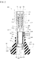
Fig. 2 is a cross-sectional side view of the valve stem. -
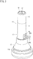
Fig. 3 is a perspective view of the valve stem. -
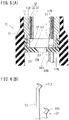
Fig. 4(A) is an enlarged perspective view of the periphery of a side surface through-hole of the valve stem, andFig. 4(B) is a perspective view of an inner sleeve. -
Fig. 5(A) is an enlarged cross-sectional side view of the periphery of the side surface through-hole of the valve stem to which a connector is attached,Fig. 5(B) is a perspective view of the connector viewed from the inner side of a stem main body through the side surface through-hole, andFig. 5(C) is a front view of the connector. -
Fig. 6(A) is an enlarged cross-sectional side view of a proximal end portion of the valve stem, andFig. 6(B) is a perspective view of a connection terminal of the connector. -
Fig. 7(A) is a perspective view of a tire valve including a valve stem according to a second embodiment, andFig. 7(B) is a perspective view of first and second conductive members. -
Fig. 8(A) is a cross-sectional plan view of the vicinity of an external electrode of the valve stem according to the second embodiment, andFig. 8(B) is a cross-sectional plan view of a portion near a proximal end of the valve stem according to the second embodiment. -
Fig. 1 shows atire valve 100 including avalve stem 10 of a first embodiment. Thetire valve 100 of the present embodiment is mounted in avalve mounting hole 81H provided in arim 81 of atire wheel 80. Specifically, a proximal end portion of thevalve stem 10 of thetire valve 100 is fitted and fixed in a state of penetrating thevalve mounting hole 81H. When thetire valve 100 is mounted to thetire wheel 80, a distal end side portion of thevalve stem 10 having an air injection port 18 (seeFig. 2 ) protrudes to the outside of thetire 82. - As shown in
Fig. 2 , thevalve stem 10 has a tubular structure in which the outer side of a stemmain body 11 having a circular tubular shape is covered with anelastic seal member 12. Specifically, a proximal end portion of the stemmain body 11 is covered with theelastic seal member 12, and a distal end side portion of the stemmain body 11 is exposed from theelastic seal member 12. An air flow hole R that communicates the inside and the outside of thetire 82 with each other is provided on the inner side of the stemmain body 11. The distal end of the stemmain body 11 is provided with theair injection port 18 described above for injecting air into thetire 82. Amale thread portion 16 is formed on an outer peripheral surface of a distal end portion of the stemmain body 11, and avalve cap 19 is screwed onto themale thread portion 16 from the outer side. The stemmain body 11 has conductivity and, for example, is made of metal. - A small-
diameter hole portion 11S having the narrowest inner diameter is formed at a position near the distal end of the air flow hole R of the stemmain body 11. A straight hole portion 11B having a larger diameter than the small-diameter hole portion 11S extends to the proximal end of the stemmain body 11 on the proximal end side of the small-diameter hole portion 11S in the air flow hole R. A proximal end side small-diameter portion 11A whose outer diameter is reduced and which extends to the proximal end of the stemmain body 11 is formed at the proximal end portion of the stemmain body 11. An annular gap is formed between an outer peripheral surface of the proximal end side small-diameter portion 11A and an inner peripheral surface of theelastic seal member 12. - A
valve core 20 is accommodated inside the stemmain body 11. The outer peripheral surface of thevalve core 20 is sealed with the inner peripheral surface of the stemmain body 11, and the air flow hole R is opened and closed by opening and closing of thevalve core 20. Specifically, thevalve core 20 is supported by atubular fixing base 29 in a state where ashaft 22 is inserted in a linearly movable manner. By linearly moving theshaft 22, avalve body 21 at the end portion of theshaft 22 opens and closes avalve port 20K at the proximal end portion of thetubular fixing base 29. Thevalve body 21 is biased by acompression coil spring 23 to a state of closing thevalve port 20K. The small-diameter hole portion 11S of the stemmain body 11 is a core fitting portion to which the valve core 20 (tubular fixing base 29) is fitted, and the inner peripheral surface of the small-diameter hole portion 11S and the outer peripheral surface of thetubular fixing base 29 are sealed. - An
annular engagement groove 12U is formed on the outer peripheral surface of the proximal end portion of theelastic seal member 12. When thetire valve 100 is mounted to thevalve mounting hole 81H of thetire wheel 80, theelastic seal member 12 is press-fitted into thevalve mounting hole 81H, and theengagement groove 12U is engaged with an opening edge of thevalve mounting hole 81H. Therefore, a portion of thevalve stem 10 on the distal end side of theengagement groove 12U is a tire outer protrudingportion 17 protruding to the outside of the tire 82 (seeFigs. 2 and3 ). In the present embodiment, the proximal end of the stemmain body 11 is disposed on the distal end side of thevalve stem 10 of theengagement groove 12U. Therefore, the tireouter protruding portion 17 includes the stemmain body 11 and part of theelastic seal member 12. Theelastic seal member 12 is made of an insulating elastomer. - As illustrated in
Fig. 2 , aninner sleeve 30 is fitted and fixed to the inner side of the stemmain body 11. Specifically, theinner sleeve 30 has a cylindrical shape, is fitted in the straight hole portion 11B of the stemmain body 11, and is disposed on the proximal end side of the small-diameter hole portion 11S and thetubular fixing base 29. - As illustrated in
Fig. 4(B) , theinner sleeve 30 is formed by covering an outer peripheral surface of an inner sleevemain body 31 having conductivity (e.g., made of metal) with aninsulating layer 32. The inner sleevemain body 31 has a cylindrical shape. Theinsulating layer 32 insulates the inner sleevemain body 31 and the stemmain body 11 from each other. - Here, the
valve stem 10 can connect electric circuits inside and outside thetire 82. Specifically, as shown inFig. 1 , when thevalve stem 10 is mounted in thevalve mounting hole 81H, for example, the proximal end portion of thevalve stem 10 is connected tocables internal circuit 91 disposed in thetire 82. The tire outer protruding portion 17 (seeFig. 2 ) of thevalve stem 10 is connected to, for example,cables external circuit 96 disposed outside thetire 82. - Examples of a tire
internal device 90 including theinternal circuit 91 include a device including asensor 92 that detects a state of thetire 82 and transmitting a detection result of thesensor 92 by theinternal circuit 91. Such asensor 92 may be, for example, a pressure sensor that detects the internal pressure of thetire 82 or a temperature sensor. Examples of the tireexternal device 95 including theexternal circuit 96 include a power supply device that supplies power to the tireinternal device 90, a receiver that receives detection data of thesensor 92 or the like of the tireinternal device 90, and the like. - Hereinafter, a structure of the
valve stem 10 for connecting theinternal circuit 91 and theexternal circuit 96 disposed inside and outside thetire 82 will be described. Thevalve stem 10 includes first and second conductive members including a pair ofinternal electrodes cables Fig. 6(A) ) and a pair ofexternal electrodes cables Figs. 4(A) and5(A) ), and being insulated from each other. In the present embodiment, the first and second conductive members are the stemmain body 11 and the inner sleevemain body 31, respectively. - As illustrated in
Fig. 6(A) , in the present embodiment, the pair ofinternal electrodes cable main body 11 and the proximal end portion of the inner sleevemain body 31, respectively.Connection terminals connector 50 are connected to the distal ends of thecables connection terminals internal electrodes valve stem 10, for example, from the radially inner side. Specifically, theconnector 50 has atubular bracket 53 having one bottomed end, and is screwed with a male thread portion formed on the outer peripheral surface of the proximal end side small-diameter portion 11A of the stemmain body 11 to be fixed to the proximal end portion of the stemmain body 11. Thebracket 53 is made of an insulating material such as resin, and insulates theconnection terminals vent 50K is formed at the center of a bottom wall of thebracket 53. The outerperipheral wall 54 of thebracket 53 is inserted into the annular gap described above formed between the proximal end side small-diameter portion 11A and theelastic seal member 12. In the present embodiment, theconnection terminals connector 50 are formed of bus bars extending in the axial direction of thevalve stem 10, and for example, the distal end portions of theconnection terminals bent portions valve stem 10 and then bent radially inward toward the distal end, where thebent portions internal electrodes valve stem 10. In the present embodiment, the proximal end side small-diameter portion 11A corresponds to an "inner connector coupling portion" described in the claims. - Next, the
external electrodes valve stem 10 connected to theexternal circuit 96 will be described. As illustrated inFigs. 2 and4(A) , a side surface through-hole 11K penetrating the inside and outside in the radial direction is formed in a portion of the stemmain body 11 exposed from theelastic seal member 12. The side surface through-hole 11K is disposed on the proximal end side of the small-diameter hole portion 11S into which thevalve core 20 is fitted in the stemmain body 11. As shown inFig. 4(A) , an opening edge of the side surface through-hole 11K constitutes oneexternal electrode 11G of thevalve stem 10. The side surface through-hole 11K is provided in a portion having a shape obtained by cutting the outer peripheral surface of the stemmain body 11 flat, and a flat surface having a quadrangular outer shape is provided at the opening edge of the side surface through-hole 11K. - As illustrated in
Fig. 4(B) , an insulating layer through-hole 32K is formed in the insulatinglayer 32 having a circular tubular shape of theinner sleeve 30 at a position near the distal end of theinner sleeve 30 in the axial direction. As a result, part of the outer peripheral surface of the portion near the distal end of the inner sleevemain body 31 is exposed from the insulating layer through-hole 32K. Furthermore, the insulating layer through-hole 32 K is provided at a position corresponding to the side surface through-hole 11K of thevalve stem 10. That is, the insulating layer through-hole 32K is provided at a position facing the side surface through-hole 11K in the radial direction of thevalve stem 10. Therefore, a portion of the inner sleevemain body 31 exposed from the insulating layer through-hole 32K is exposed to the outside from the side surface through-hole 11K of the stemmain body 11. This exposed portion of the inner sleevemain body 31 constitutes the otherexternal electrode 31G of thevalve stem 10. The opening diameter of the insulating layer through-hole 32K is smaller than the opening diameter of the side surface through-hole 11K of the stemmain body 11, and the entire opening edge of the insulating layer through-hole 32K is exposed from the side surface through-hole 11K of the stemmain body 11. Theinner sleeve 30 is adhered to the inner surface of the stemmain body 11 to seal the side surface through-hole 11K. - As shown in
Fig. 5(A) , for example,connection terminals connector 40 are respectively connected to the distal ends of thecables tire 82, and theconnection terminals external electrodes Figs. 5(B) and 5(C) , theconnector 40 includes agasket 45 made of an insulating member that couples and fixes thecables connection terminals 41 and 42 (Note that inFig. 5(B) , theinner sleeve 30 is not illustrated). Thegasket 45 has a disk-shapedbase 43 and has a pair of fittingarcuate protrusions 44 protruding out from an opposing surface of the disk-shapedbase 43 to thevalve stem 10. The disk-shapedbase 43 abuts on the flat surface of the opening edge of the side surface through-hole 11K of the stemmain body 11. Then, the distal end portion of one of theconnection terminals 41 linearly protruding from the disk-shapedbase 43 of theconnector 40 abuts on theexternal electrode 31G on the outer peripheral surface of the inner sleevemain body 31 through the insulating layer through-hole 32K. For example, theconnection terminal 41 is formed of a bus bar and has a shape in which the distal end portion is bent. In addition, theother connection terminal 42 extending radially outward from the disk-shapedbase 43 of theconnector 40 along the disk-shapedbase 43 abuts on theexternal electrode 11G (e.g., the proximal end side opening edge of the side surface through-hole 11K) of the stemmain body 11. For example, theconnection terminal 42 is formed of a bus bar, and has a shape in which a distal end portion is slightly bent toward a side away from the disk-shapedbase 43. This facilitates contact between theconnection terminal 42 and theexternal electrode 11G of the stemmain body 11. The pair of fittingarcuate protrusions 44 has an arcuate shape along the outer edge of the disk-shapedbase 43, and the outer peripheral surface of the fittingarcuate protrusion 44 is fitted into the side surface through-hole 11K of the stem main body 11 (theconnection terminals gasket 45 is formed of an elastomer and the outer peripheral radius of the fittingarcuate protrusion 44 is made larger than the inner peripheral radius of the side surface through-hole 11K of the stemmain body 11, the attachment of theconnector 40 to thevalve stem 10 can be stabilized by pushing the fittingarcuate protrusion 44 into the side surface through-hole 11K. In the present embodiment, the side surface through-hole 11K of the stemmain body 11, the opening edge (external electrode 11G) thereof, and theexternal electrode 31G constitute aconnector coupling portion 13 coupled to theconnector 40. - As described above, the
valve stem 10 of the present embodiment is connected to thecables cables internal circuit 91 inside thetire 82 and theexternal circuit 96 outside thetire 82. - In the
valve stem 10 and thetire valve 100 of the present embodiment, the first and second conductive members (stemmain body 11 and inner sleeve main body 31) insulated from each other are provided, and such first and second conductive members include theinternal electrodes internal circuit 91 in thetire 82 and theexternal electrodes external circuit 96 outside thetire 82, respectively. Here, theexternal electrodes portion 17 of thevalve stem 10 protruding outside thetire 82. As a result, the circuits inside and outside thetire 82 can be connected even in a state where thevalve cap 19 is removed from thevalve stem 10. For example, even when thevalve cap 19 is removed and air is supplied into thetire 82 through thevalve stem 10, power can be supplied to theinternal circuit 91 in thetire 82. In addition, since theexternal electrodes valve core 20, theinternal circuit 91 and theexternal circuit 96 can be connected regardless of the position of thevalve body 21. - In addition, in the
valve stem 10, the outer peripheral surface of the tire outer protrudingportion 17 is provided with the pair ofexternal electrodes hole 11K) to which theconnector 40 provided in theexternal circuit 96 is fitted, so that theconnector 40 of theexternal circuit 96 is easily coupled to the stemmain body 11, and connection with theexternal circuit 96 is facilitated. When theconnector 40 is not connected to theexternal electrodes external electrodes main body 11. - In addition, in the
valve stem 10, the pair ofexternal electrodes diameter hole portion 11S in the tire outer protrudingportion 17, and hence interference with thevalve core 20 can be prevented even when the conductive member is disposed on the inner side of thevalve stem 10 as in theinner sleeve 30. -
Fig. 7(A) shows avalve stem 10V and atire valve 100V including the same of a second embodiment. The valve stem 10V and thetire valve 100V are different from thevalve stem 10 and thetire valve 100 of the first embodiment in that a stemmain body 11V is made of an insulating resin. The valve stem 10V has a tubular structure in which a middle portion in the axial direction of the cylindrical stemmain body 11 is surrounded by theelastic seal member 12. Similarly to the first embodiment, theelastic seal member 12 is press-fitted into thevalve mounting hole 81H (seeFig. 1 ) of thetire wheel 80, and the stemmain body 11V is provided with the small-diameter hole portion 11S (seeFig. 2 ) to which thevalve core 20 is fitted, and thevalve core 20 is accommodated. In thetire valve 100V, the valve cap is screwed from the outer side onto the male thread portion provided on the outer peripheral surface of the distal end portion of the stemmain body 11V. - In the present embodiment, first and second
conductive members Fig. 1 ) inside thetire 82 and theexternal circuit 96 outside thetire 82 are embedded in the stemmain body 11V in a state of being insulated from each other. As shown inFigs. 7(A) and 7(B) , the first and secondconductive members tire 82 is exposed from the stemmain body 11V. The exposed proximal end portions of the first and secondconductive members internal electrodes cables conductive members main body 11V when viewed from the axial direction of thevalve stem 10V (seeFigs. 8(A) and 8(B) ), and are formed of, for example, a metal bus bar. - As shown in
Figs. 7(A) and8(A) , portions of the first and secondconductive members portion 17 and exposed on the outer peripheral surface of the stemmain body 11V. The exposed portions are a pair ofexternal electrodes cable side surface openings main body 11V near the distal end exposed from theelastic seal member 12, and outer side surfaces of a portion of the first and secondconductive members side surface openings external electrodes side surface openings external circuit 96, so thatexternal electrodes main body 11V. - Also in the valve stem 10V and the
tire valve 100V of the present embodiment, since theexternal electrodes valve stem 10V, the circuits inside and outside thetire 82 can be connected even in a state where the valve cap is removed. Since the first and secondconductive members main body 11V, they do not interfere with thevalve core 20. Therefore, theexternal electrodes valve stem 10V to which thevalve core 20 is fitted, or may be at the same position as the core fitting portion in the axial direction of thevalve stem 10V. -
- (1) In the first embodiment, the tubular member (inner sleeve main body 31) is provided as the conductive member including the
internal electrode 31N and theexternal electrode 31G, but may be a rod-shaped member. - (2) In the first embodiment, the conductive member (inner sleeve main body 31) including the
internal electrode 31N and theexternal electrode 31G is provided on the inner side of the stemmain body 11, but may be provided on the outer side. In this case, for example, portions other than the distal end portion and the proximal end portion of the conductive member may be embedded in theelastic seal member 12 to be insulated from the stemmain body 11. The conductive member may be, for example, a rod shape or a circular tubular shape (e.g., concentric with the stem main body 11). - (3) In the first embodiment, the
internal electrode 31N of thevalve stem 10 connected to theinternal circuit 91 may be a conductive additional component abutting on the inner sleevemain body 31. In addition, theinternal electrode 11N of thevalve stem 10 connected to theinternal circuit 91 may be a conductive additional component abutting on the stemmain body 11. These components include, for example,connection terminals connection terminals main body 11 and the inner sleevemain body 31, respectively, and are provided on thevalve stem 10, instead of being provided on theinternal circuit 91 side (cable - (4) In the first embodiment, the
external electrode 11G of thevalve stem 10 connected to theexternal circuit 96 may be a conductive additional component abutting on the stemmain body 11. In addition, theexternal electrode 31G of thevalve stem 10 connected to theexternal circuit 96 may be a conductive component abutting on the inner sleeve main body 31 (e.g., one end portion of a penetrating component may be connected to the inner sleevemain body 31, and the other end portion may be exposed in the side surface through-hole 11K). These components include, for example,connection terminals connection terminals main body 31 and the stem main body 11 (e.g., the opening edge of the side surface through-hole 11K) and are provided on thevalve stem 10, respectively, instead of being provided on theexternal circuit 96 side (cable - (5) In the first embodiment, the
external electrode 11G of the stemmain body 11 is disposed at the opening edge of the side surface through-hole 11K, but may not be disposed in the vicinity of the side surface through-hole 11K (i.e., the vicinity of theexternal electrode 31G of the inner sleeve main body 31). For example, theexternal electrode 11G of the stemmain body 11 may be disposed on the outer peripheral surface of the distal end portion of thevalve stem 10. -
- 10, 10V
- Valve stem
- 11, 11V
- Stem main body
- 11G
- External electrode
- 11N
- Internal electrode
- 17
- Tire outer protruding portion
- 20
- Valve core
- 30
- Inner sleeve
- 31
- Inner sleeve main body
- 31G
- External electrode
- 31N
- Internal electrode
- 71
- First conductive member
- 71G
- External electrode
- 71N
- Internal electrode
- 72
- Second conductive member
- 72G
- External electrode
- 72N
- Internal electrode
- 80
- Tire wheel
- 81H
- Valve mounting hole
- 82
- Tire
- 91
- Internal circuit
- 96
- External circuit
- 100, 100V
- Tire valve
Claims (9)
- A valve stem having a tubular structure, being fixed in a state of penetrating a valve mounting hole of a tire wheel, and accommodating a valve core, the valve stem comprising:a pair of internal electrodes connected to an internal circuit in a tire;a pair of external electrodes arranged on an outer peripheral surface of a tire outer protruding portion protruding to an outside of the tire in the valve stem and connectable to an external circuit outside the tire; andfirst and second conductive members having the internal electrodes and the external electrodes and insulated from each other.
- The valve stem according to claim 1, wherein the outer peripheral surface of the tire outer protruding portion is provided with a connector coupling portion having the pair of external electrodes and coupled to a connector provided in the external circuit.
- The valve stem according to claim 1 or 2, further comprising:a core fitting portion to which a tubular fixing base of the valve core is fitted at a position near a distal end of the tire outer protruding portion, whereinthe pair of external electrodes is disposed on a proximal end side of the core fitting portion in the tire outer protruding portion.
- The valve stem according to claim 3, further comprising:a conductive stem main body having a tubular structure, having the core fitting portion on an inner side, and being partially included in the tire outer protruding portion;a side surface through-hole laterally penetrating a proximal end side portion of the core fitting portion in the stem main body of the tire outer protruding portion; andan inner sleeve covering an outer side surface of a conductive inner sleeve main body with an insulating layer, the inner sleeve being fitted to an inner side of the proximal end side portion of the core fitting portion in the stem main body to seal the side surface through-hole, whereinthe stem main body forms part or whole of the first conductive member,the external electrode of the first conductive member is an opening edge of the side surface through-hole of the stem main body or an additional component fixed to the opening edge,the inner sleeve main body forms part or whole of the second conductive member, andthe external electrode of the second conductive member is part of the inner sleeve main body exposed to the outside by providing an opening corresponding to the side surface through-hole in the insulating layer, or is a penetrating component that penetrates the insulating layer and has one end portion connected to the inner sleeve main body and an other end portion exposed in the side surface through-hole.
- The valve stem according to claim 4, whereinthe side surface through-hole forms an outer connector fitting portion to which a connector connected to the pair of external electrodes of the external circuit is fitted,the external electrode of the first conductive member is the opening edge of the side surface through-hole of the stem main body, andthe external electrode of the second conductive member is part of the inner sleeve main body exposed to the outside through the opening of the insulating layer.
- The valve stem according to claim 4 or 5, whereina proximal end portion of the stem main body is provided with an inner connector coupling portion coupled to a connector connected to the pair of internal electrodes of the internal circuit,the internal electrode of the first conductive member is the proximal end portion of the stem main body, andthe internal electrode of the second conductive member is a proximal end portion of the inner sleeve main body.
- The valve stem according to claim 1 or 2, further comprising:an insulating resin stem main body having a tubular structure, having a core fitting portion to which the valve core is fitted on an inner side, and being partially included in the tire outer protruding portion;a pair of bus bars embedded in the stem main body to form the first and second conductive members; anda side surface opening formed in a state of being recessed in an outer side surface of the stem main body, a portion near one ends of the pair of bus bars being exposed inside the side surface opening, whereinthe pair of external electrodes is portions near the one ends of the pair of bus bars exposed inside the side surface opening.
- The valve stem according to claim 7, wherein other end portions of the pair of bus bars protrude from a proximal end face of the stem main body to form the pair of internal electrodes.
- A tire valve comprising: the valve stem according to any one of claims 1 to 8; and a valve core assembled in the valve stem.
Applications Claiming Priority (2)
| Application Number | Priority Date | Filing Date | Title |
|---|---|---|---|
| JP2020136058A JP7329482B2 (en) | 2020-08-11 | 2020-08-11 | valve stems and tire valves |
| PCT/JP2021/013547 WO2022034713A1 (en) | 2020-08-11 | 2021-03-30 | Valve stem and tire valve |
Publications (2)
| Publication Number | Publication Date |
|---|---|
| EP4119364A1 true EP4119364A1 (en) | 2023-01-18 |
| EP4119364A4 EP4119364A4 (en) | 2023-11-08 |
Family
ID=80247038
Family Applications (1)
| Application Number | Title | Priority Date | Filing Date |
|---|---|---|---|
| EP21855792.4A Withdrawn EP4119364A4 (en) | 2020-08-11 | 2021-03-30 | Valve stem and tire valve |
Country Status (5)
| Country | Link |
|---|---|
| US (1) | US20230158843A1 (en) |
| EP (1) | EP4119364A4 (en) |
| JP (1) | JP7329482B2 (en) |
| CN (1) | CN115427237A (en) |
| WO (1) | WO2022034713A1 (en) |
Families Citing this family (2)
| Publication number | Priority date | Publication date | Assignee | Title |
|---|---|---|---|---|
| US11879764B2 (en) * | 2021-03-03 | 2024-01-23 | Dan Haronian | Liquid height level device |
| US20240025215A1 (en) * | 2021-03-03 | 2024-01-25 | Dan Haronian | Liquid height level system |
Family Cites Families (21)
| Publication number | Priority date | Publication date | Assignee | Title |
|---|---|---|---|---|
| US3665387A (en) * | 1970-08-31 | 1972-05-23 | Goodyear Tire & Rubber | Signalling system for low tire condition on a vehicle |
| US4117281A (en) * | 1977-03-08 | 1978-09-26 | Eaton Corporation | Combination tire pressure monitoring switch and inflation valve |
| US4310014A (en) * | 1980-06-27 | 1982-01-12 | General Motors Corporation | Tire pressure indicator integral with tire stem |
| JPH0288313A (en) * | 1988-09-26 | 1990-03-28 | Bridgestone Corp | Tire valve and tire inspection device |
| US4951501A (en) * | 1989-10-16 | 1990-08-28 | Schrader Automotive Inc. | Tire valve having dual electric conducting paths |
| JPH08178784A (en) * | 1994-12-22 | 1996-07-12 | Pacific Ind Co Ltd | Tire air pressure alarm |
| US5853020A (en) * | 1995-06-23 | 1998-12-29 | Widner; Ronald D. | Miniature combination valve and pressure transducer and system |
| JPH09150612A (en) * | 1995-11-30 | 1997-06-10 | Hitachi Vlsi Eng Corp | Automotive tire pressure management system |
| TW404354U (en) * | 1999-03-30 | 2000-09-01 | Huang Teng Yi | Power supply unit installation structure for a hiding type tire pressure detector |
| US6407662B1 (en) * | 1999-04-29 | 2002-06-18 | Fernando Gomez De Sebastian | System to monitor conditions in a fluid-containing member |
| US6693547B1 (en) * | 2002-05-09 | 2004-02-17 | Honda Giken Kogyo Kabushiki Kaisha | Device and method for extending the lifetime of a battery in a tire pressure sensor |
| US20040025581A1 (en) * | 2002-08-08 | 2004-02-12 | Miller Laurence Dean | Method and apparatus for monitoring tire pressure with a color indicator |
| JP4271530B2 (en) * | 2003-08-08 | 2009-06-03 | 太平洋工業株式会社 | Tire valve |
| JP2005178676A (en) * | 2003-12-22 | 2005-07-07 | Kyoei Sangyo Kk | Tire valve cap and tire pressure management apparatus using the cap |
| JP2008143297A (en) * | 2006-12-08 | 2008-06-26 | Toyota Motor Corp | Air leak risk assessment system |
| WO2009057214A1 (en) * | 2007-11-01 | 2009-05-07 | Renesas Technology Corp. | Automobile control system and valve |
| JP5658734B2 (en) * | 2012-12-27 | 2015-01-28 | 住友ゴム工業株式会社 | Valve unit |
| JP6636344B2 (en) * | 2016-01-22 | 2020-01-29 | 太平洋工業株式会社 | Valve core |
| JP2018131161A (en) * | 2017-02-17 | 2018-08-23 | 株式会社Soken | Tire state detection system |
| WO2019193744A1 (en) | 2018-04-06 | 2019-10-10 | 太平洋工業株式会社 | Tire valve |
| CN110546418A (en) * | 2018-03-29 | 2019-12-06 | 太平洋工业株式会社 | Spool and tire valve |
-
2020
- 2020-08-11 JP JP2020136058A patent/JP7329482B2/en active Active
-
2021
- 2021-03-30 US US17/919,837 patent/US20230158843A1/en not_active Abandoned
- 2021-03-30 WO PCT/JP2021/013547 patent/WO2022034713A1/en not_active Ceased
- 2021-03-30 EP EP21855792.4A patent/EP4119364A4/en not_active Withdrawn
- 2021-03-30 CN CN202180027872.5A patent/CN115427237A/en active Pending
Also Published As
| Publication number | Publication date |
|---|---|
| JP7329482B2 (en) | 2023-08-18 |
| EP4119364A4 (en) | 2023-11-08 |
| WO2022034713A1 (en) | 2022-02-17 |
| JP2022032369A (en) | 2022-02-25 |
| US20230158843A1 (en) | 2023-05-25 |
| CN115427237A (en) | 2022-12-02 |
Similar Documents
| Publication | Publication Date | Title |
|---|---|---|
| US8430696B2 (en) | Connector having improved fitting properties | |
| EP2693574B1 (en) | Shield connector | |
| US10128607B2 (en) | Sealed connector system | |
| US11101604B2 (en) | Connector | |
| EP4119364A1 (en) | Valve stem and tire valve | |
| EP2523258A1 (en) | Electrical wire holding device | |
| US20130330952A1 (en) | Connector with small housing | |
| MXPA03005991A (en) | Separable electrical connector assembly. | |
| US10446972B2 (en) | Electrical connector | |
| US11296453B2 (en) | Waterproof structure of connector | |
| CN111937253B (en) | Connector | |
| WO2019193744A1 (en) | Tire valve | |
| US20110273854A1 (en) | Magnetic Field Sensor | |
| US20220399679A1 (en) | Connector and connector-equipped electric wire | |
| US4810198A (en) | Reinforced boot for spark plug cables | |
| US20250079776A1 (en) | Relay connector | |
| JP2012151029A (en) | Relay connector | |
| US12308560B2 (en) | Hermetic terminal and tank valve device including same | |
| US20240266773A1 (en) | Relay connector | |
| US12107372B2 (en) | Electrical connector having a contacting element designed as a cast part | |
| JP2012138182A (en) | Relay connector | |
| CN113748575A (en) | Connector with a locking member | |
| US20260031567A1 (en) | Relay connector | |
| CN217823249U (en) | Waterproof unmanned aerial vehicle antenna structure | |
| JP2002270281A (en) | Waterproof shield connector |
Legal Events
| Date | Code | Title | Description |
|---|---|---|---|
| STAA | Information on the status of an ep patent application or granted ep patent |
Free format text: STATUS: THE INTERNATIONAL PUBLICATION HAS BEEN MADE |
|
| PUAI | Public reference made under article 153(3) epc to a published international application that has entered the european phase |
Free format text: ORIGINAL CODE: 0009012 |
|
| STAA | Information on the status of an ep patent application or granted ep patent |
Free format text: STATUS: REQUEST FOR EXAMINATION WAS MADE |
|
| 17P | Request for examination filed |
Effective date: 20221014 |
|
| AK | Designated contracting states |
Kind code of ref document: A1 Designated state(s): AL AT BE BG CH CY CZ DE DK EE ES FI FR GB GR HR HU IE IS IT LI LT LU LV MC MK MT NL NO PL PT RO RS SE SI SK SM TR |
|
| STAA | Information on the status of an ep patent application or granted ep patent |
Free format text: STATUS: EXAMINATION IS IN PROGRESS |
|
| STAA | Information on the status of an ep patent application or granted ep patent |
Free format text: STATUS: THE APPLICATION HAS BEEN WITHDRAWN |
|
| A4 | Supplementary search report drawn up and despatched |
Effective date: 20231010 |
|
| RIC1 | Information provided on ipc code assigned before grant |
Ipc: B60C 29/02 20060101ALI20231004BHEP Ipc: B60C 23/04 20060101AFI20231004BHEP |
|
| DAV | Request for validation of the european patent (deleted) | ||
| DAX | Request for extension of the european patent (deleted) | ||
| 17Q | First examination report despatched |
Effective date: 20231020 |
|
| 18W | Application withdrawn |
Effective date: 20231023 |