EP4119319A1 - Method of fabric processing for improved cmc infiltration - Google Patents
Method of fabric processing for improved cmc infiltration Download PDFInfo
- Publication number
- EP4119319A1 EP4119319A1 EP22184957.3A EP22184957A EP4119319A1 EP 4119319 A1 EP4119319 A1 EP 4119319A1 EP 22184957 A EP22184957 A EP 22184957A EP 4119319 A1 EP4119319 A1 EP 4119319A1
- Authority
- EP
- European Patent Office
- Prior art keywords
- woven fabric
- fabric tape
- roller
- protrusions
- spiked
- Prior art date
- Legal status (The legal status is an assumption and is not a legal conclusion. Google has not performed a legal analysis and makes no representation as to the accuracy of the status listed.)
- Granted
Links
Images


Classifications
-
- B—PERFORMING OPERATIONS; TRANSPORTING
- B29—WORKING OF PLASTICS; WORKING OF SUBSTANCES IN A PLASTIC STATE IN GENERAL
- B29B—PREPARATION OR PRETREATMENT OF THE MATERIAL TO BE SHAPED; MAKING GRANULES OR PREFORMS; RECOVERY OF PLASTICS OR OTHER CONSTITUENTS OF WASTE MATERIAL CONTAINING PLASTICS
- B29B15/00—Pretreatment of the material to be shaped, not covered by groups B29B7/00 - B29B13/00
- B29B15/08—Pretreatment of the material to be shaped, not covered by groups B29B7/00 - B29B13/00 of reinforcements or fillers
- B29B15/10—Coating or impregnating independently of the moulding or shaping step
- B29B15/12—Coating or impregnating independently of the moulding or shaping step of reinforcements of indefinite length
- B29B15/122—Coating or impregnating independently of the moulding or shaping step of reinforcements of indefinite length with a matrix in liquid form, e.g. as melt, solution or latex
- B29B15/127—Coating or impregnating independently of the moulding or shaping step of reinforcements of indefinite length with a matrix in liquid form, e.g. as melt, solution or latex by spraying
-
- C—CHEMISTRY; METALLURGY
- C04—CEMENTS; CONCRETE; ARTIFICIAL STONE; CERAMICS; REFRACTORIES
- C04B—LIME, MAGNESIA; SLAG; CEMENTS; COMPOSITIONS THEREOF, e.g. MORTARS, CONCRETE OR LIKE BUILDING MATERIALS; ARTIFICIAL STONE; CERAMICS; REFRACTORIES; TREATMENT OF NATURAL STONE
- C04B35/00—Shaped ceramic products characterised by their composition; Ceramics compositions; Processing powders of inorganic compounds preparatory to the manufacturing of ceramic products
- C04B35/71—Ceramic products containing macroscopic reinforcing agents
- C04B35/78—Ceramic products containing macroscopic reinforcing agents containing non-metallic materials
- C04B35/80—Fibres, filaments, whiskers, platelets, or the like
-
- B—PERFORMING OPERATIONS; TRANSPORTING
- B28—WORKING CEMENT, CLAY, OR STONE
- B28B—SHAPING CLAY OR OTHER CERAMIC COMPOSITIONS; SHAPING SLAG; SHAPING MIXTURES CONTAINING CEMENTITIOUS MATERIAL, e.g. PLASTER
- B28B23/00—Arrangements specially adapted for the production of shaped articles with elements wholly or partly embedded in the moulding material; Production of reinforced objects
- B28B23/0006—Arrangements specially adapted for the production of shaped articles with elements wholly or partly embedded in the moulding material; Production of reinforced objects the reinforcement consisting of aligned, non-metal reinforcing elements
-
- C—CHEMISTRY; METALLURGY
- C04—CEMENTS; CONCRETE; ARTIFICIAL STONE; CERAMICS; REFRACTORIES
- C04B—LIME, MAGNESIA; SLAG; CEMENTS; COMPOSITIONS THEREOF, e.g. MORTARS, CONCRETE OR LIKE BUILDING MATERIALS; ARTIFICIAL STONE; CERAMICS; REFRACTORIES; TREATMENT OF NATURAL STONE
- C04B35/00—Shaped ceramic products characterised by their composition; Ceramics compositions; Processing powders of inorganic compounds preparatory to the manufacturing of ceramic products
- C04B35/515—Shaped ceramic products characterised by their composition; Ceramics compositions; Processing powders of inorganic compounds preparatory to the manufacturing of ceramic products based on non-oxide ceramics
- C04B35/56—Shaped ceramic products characterised by their composition; Ceramics compositions; Processing powders of inorganic compounds preparatory to the manufacturing of ceramic products based on non-oxide ceramics based on carbides or oxycarbides
- C04B35/565—Shaped ceramic products characterised by their composition; Ceramics compositions; Processing powders of inorganic compounds preparatory to the manufacturing of ceramic products based on non-oxide ceramics based on carbides or oxycarbides based on silicon carbide
-
- C—CHEMISTRY; METALLURGY
- C04—CEMENTS; CONCRETE; ARTIFICIAL STONE; CERAMICS; REFRACTORIES
- C04B—LIME, MAGNESIA; SLAG; CEMENTS; COMPOSITIONS THEREOF, e.g. MORTARS, CONCRETE OR LIKE BUILDING MATERIALS; ARTIFICIAL STONE; CERAMICS; REFRACTORIES; TREATMENT OF NATURAL STONE
- C04B35/00—Shaped ceramic products characterised by their composition; Ceramics compositions; Processing powders of inorganic compounds preparatory to the manufacturing of ceramic products
- C04B35/622—Forming processes; Processing powders of inorganic compounds preparatory to the manufacturing of ceramic products
- C04B35/626—Preparing or treating the powders individually or as batches ; preparing or treating macroscopic reinforcing agents for ceramic products, e.g. fibres; mechanical aspects section B
- C04B35/628—Coating the powders or the macroscopic reinforcing agents
- C04B35/62884—Coating the powders or the macroscopic reinforcing agents by gas phase techniques
-
- C—CHEMISTRY; METALLURGY
- C04—CEMENTS; CONCRETE; ARTIFICIAL STONE; CERAMICS; REFRACTORIES
- C04B—LIME, MAGNESIA; SLAG; CEMENTS; COMPOSITIONS THEREOF, e.g. MORTARS, CONCRETE OR LIKE BUILDING MATERIALS; ARTIFICIAL STONE; CERAMICS; REFRACTORIES; TREATMENT OF NATURAL STONE
- C04B35/00—Shaped ceramic products characterised by their composition; Ceramics compositions; Processing powders of inorganic compounds preparatory to the manufacturing of ceramic products
- C04B35/622—Forming processes; Processing powders of inorganic compounds preparatory to the manufacturing of ceramic products
- C04B35/626—Preparing or treating the powders individually or as batches ; preparing or treating macroscopic reinforcing agents for ceramic products, e.g. fibres; mechanical aspects section B
- C04B35/63—Preparing or treating the powders individually or as batches ; preparing or treating macroscopic reinforcing agents for ceramic products, e.g. fibres; mechanical aspects section B using additives specially adapted for forming the products, e.g.. binder binders
- C04B35/632—Organic additives
- C04B35/634—Polymers
- C04B35/63404—Polymers obtained by reactions only involving carbon-to-carbon unsaturated bonds
- C04B35/63416—Polyvinylalcohols [PVA]; Polyvinylacetates
-
- C—CHEMISTRY; METALLURGY
- C04—CEMENTS; CONCRETE; ARTIFICIAL STONE; CERAMICS; REFRACTORIES
- C04B—LIME, MAGNESIA; SLAG; CEMENTS; COMPOSITIONS THEREOF, e.g. MORTARS, CONCRETE OR LIKE BUILDING MATERIALS; ARTIFICIAL STONE; CERAMICS; REFRACTORIES; TREATMENT OF NATURAL STONE
- C04B35/00—Shaped ceramic products characterised by their composition; Ceramics compositions; Processing powders of inorganic compounds preparatory to the manufacturing of ceramic products
- C04B35/622—Forming processes; Processing powders of inorganic compounds preparatory to the manufacturing of ceramic products
- C04B35/626—Preparing or treating the powders individually or as batches ; preparing or treating macroscopic reinforcing agents for ceramic products, e.g. fibres; mechanical aspects section B
- C04B35/63—Preparing or treating the powders individually or as batches ; preparing or treating macroscopic reinforcing agents for ceramic products, e.g. fibres; mechanical aspects section B using additives specially adapted for forming the products, e.g.. binder binders
- C04B35/632—Organic additives
- C04B35/634—Polymers
- C04B35/63404—Polymers obtained by reactions only involving carbon-to-carbon unsaturated bonds
- C04B35/6342—Polyvinylacetals, e.g. polyvinylbutyral [PVB]
-
- D—TEXTILES; PAPER
- D03—WEAVING
- D03D—WOVEN FABRICS; METHODS OF WEAVING; LOOMS
- D03D3/00—Woven fabrics characterised by their shape
- D03D3/005—Tapes or ribbons not otherwise provided for
-
- C—CHEMISTRY; METALLURGY
- C04—CEMENTS; CONCRETE; ARTIFICIAL STONE; CERAMICS; REFRACTORIES
- C04B—LIME, MAGNESIA; SLAG; CEMENTS; COMPOSITIONS THEREOF, e.g. MORTARS, CONCRETE OR LIKE BUILDING MATERIALS; ARTIFICIAL STONE; CERAMICS; REFRACTORIES; TREATMENT OF NATURAL STONE
- C04B2235/00—Aspects relating to ceramic starting mixtures or sintered ceramic products
- C04B2235/02—Composition of constituents of the starting material or of secondary phases of the final product
- C04B2235/30—Constituents and secondary phases not being of a fibrous nature
- C04B2235/38—Non-oxide ceramic constituents or additives
- C04B2235/3817—Carbides
- C04B2235/3826—Silicon carbides
-
- C—CHEMISTRY; METALLURGY
- C04—CEMENTS; CONCRETE; ARTIFICIAL STONE; CERAMICS; REFRACTORIES
- C04B—LIME, MAGNESIA; SLAG; CEMENTS; COMPOSITIONS THEREOF, e.g. MORTARS, CONCRETE OR LIKE BUILDING MATERIALS; ARTIFICIAL STONE; CERAMICS; REFRACTORIES; TREATMENT OF NATURAL STONE
- C04B2235/00—Aspects relating to ceramic starting mixtures or sintered ceramic products
- C04B2235/02—Composition of constituents of the starting material or of secondary phases of the final product
- C04B2235/50—Constituents or additives of the starting mixture chosen for their shape or used because of their shape or their physical appearance
- C04B2235/52—Constituents or additives characterised by their shapes
- C04B2235/5208—Fibers
- C04B2235/5216—Inorganic
- C04B2235/524—Non-oxidic, e.g. borides, carbides, silicides or nitrides
- C04B2235/5244—Silicon carbide
-
- C—CHEMISTRY; METALLURGY
- C04—CEMENTS; CONCRETE; ARTIFICIAL STONE; CERAMICS; REFRACTORIES
- C04B—LIME, MAGNESIA; SLAG; CEMENTS; COMPOSITIONS THEREOF, e.g. MORTARS, CONCRETE OR LIKE BUILDING MATERIALS; ARTIFICIAL STONE; CERAMICS; REFRACTORIES; TREATMENT OF NATURAL STONE
- C04B2235/00—Aspects relating to ceramic starting mixtures or sintered ceramic products
- C04B2235/02—Composition of constituents of the starting material or of secondary phases of the final product
- C04B2235/50—Constituents or additives of the starting mixture chosen for their shape or used because of their shape or their physical appearance
- C04B2235/52—Constituents or additives characterised by their shapes
- C04B2235/5208—Fibers
- C04B2235/5252—Fibers having a specific pre-form
- C04B2235/5256—Two-dimensional, e.g. woven structures
-
- C—CHEMISTRY; METALLURGY
- C04—CEMENTS; CONCRETE; ARTIFICIAL STONE; CERAMICS; REFRACTORIES
- C04B—LIME, MAGNESIA; SLAG; CEMENTS; COMPOSITIONS THEREOF, e.g. MORTARS, CONCRETE OR LIKE BUILDING MATERIALS; ARTIFICIAL STONE; CERAMICS; REFRACTORIES; TREATMENT OF NATURAL STONE
- C04B2235/00—Aspects relating to ceramic starting mixtures or sintered ceramic products
- C04B2235/60—Aspects relating to the preparation, properties or mechanical treatment of green bodies or pre-forms
- C04B2235/614—Gas infiltration of green bodies or pre-forms
Definitions
- the present invention relates to ceramic matrix composites, and more particularly, to the preparation of woven ceramic fabrics for use in ceramic matrix composites.
- CMCs ceramic matrix composites
- voids that exist between adjacent tows of a preform that can become large defects after matrix infiltration. Such defects diminish interlaminar strength of the composite structure.
- Reducing tow size i.e., the number of filaments per tow
- a method of preparing a woven fabric material for use in a ceramic matrix composite includes securing a woven fabric tape in tension across a roller, the roller having an outer surface with a plurality of spiked protrusions extending radially therefrom, each of the plurality of spiked protrusions having a diameter between 10 microns and 500 microns.
- the method further includes passing the woven fabric along the roller, such that the roller rotates with the passing of the woven fabric tape, thereby impinging the spiked protrusions into the woven fabric tape, and separating filaments within tows of the woven fabric tape by penetration of at least one of the spiked protrusions into the woven fabric tape, such that filaments within various tows of the woven fabric tape are pushed apart to form a separated woven fabric tape with a greater number of tows per unit area than the woven fabric tape.
- a system for processing a woven fabric tape for use in a ceramic matrix composite includes a first roller having an outer surface with a plurality of spiked protrusions and a tensioning means disposed to retain the woven fabric tape in contact with at least a subset of the spiked protrusions of the first roller.
- Each of the plurality of spiked protrusions has a diameter between 10 microns and 500 microns.
- This disclosure presents a system and method for separating tows within a woven ceramic fabric.
- the woven fabric can be passed over one or more rollers having protrusions (studs, pins, etc.) sized and spaced to mechanically separate the tows to increase tow number and decrease tow-to-tow spacing.
- the separated fabric has a more uniform pore distribution, which facilitates more even infiltration with ceramic particles during densification.
- FIG. 1 is a simplified illustration of system 10 used to separate tows 12 (labeled in FIG. 2 ) of woven fabric tape 14.
- System 10 includes first applicator 16, roller 18, air knife 20, and second applicator 22.
- FIG. 2 is an enlarged partial view of roller 18 including protrusions 24.
- FIGS. 3 and 4 are simplified plan views of protrusions 24, represented as circles, in standard and staggered distributions (roller 18 is omitted for simplicity).
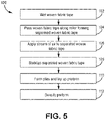
- FIG. 5 is a flowchart illustrating selected steps of method 100, used to prepare woven fabric tape 14 for use in a CMC. Steps 102-112 of method 100 are described below in combination with FIGS. 1-4 . FIGS. 1-5 are discussed together.
- Woven fabric tape 14 is formed from warp and weft tows 12 of bundled silicon carbide filaments. Other suitable ceramics are contemplated herein. Woven fabric tape 14 can be arranged in various weave patterns such as plain, harness (e.g., 3, 5, 8, etc.), twill, braid, or non-symmetric.
- woven fabric tape 14 can be optionally wetted to facilitate mechanical separation of tows 12.
- First applicator 16 can be a sprayer, bath, or other source of a solution of water or ethanol with a polymer material such as poly-vinyl alcohol (PVA) or poly-vinyl butyral (PVB) to be applied to woven fabric tape 14. Wetting can help reduce friction from roller 18 and protrusions 24 and protect filaments from breakage during the separation process.
- PVA poly-vinyl alcohol
- PVB poly-vinyl butyral
- woven fabric tape 14 is passed along roller 18 to form a separated woven fabric tape 14.
- Roller 18 includes outer surface 26 with a number of protrusions 24 circumscribing roller 18.
- Protrusions 24 can be "spiked” in the sense that they are sized and shaped for at least partial insertion into or through tows 12, to separate tows 12 into smaller clusters or subtows of fewer filaments.
- Roller 18 and protrusions 24 can be formed from a metal or hard polymer material.
- Each protrusion 24 is connected to roller 18 by a base 28 and has an oppositely disposed tip 30. In an exemplary embodiment, tip 30 can be rounded to help prevent breakage of the filaments as a protrusion 24 is inserted into a tow 12. As shown in FIG.
- each protrusion 24 can taper in the direction from base 28 to tip 30.
- Diameter d of protrusion 24 measured at base 28 can be 10 to 500 microns, and more specifically, 100 to 300 microns, to allow for the desired degree of penetration into and separation of tows 12 in woven tape 14 having the various weave patterns listed above.
- the same dimensions for diameter d can further apply to a non-tapered protrusion 24. In such an embodiment, diameter d as measured at base 28 and tip 30 would generally be the same.
- Protrusions 24 can have a standard distribution along outer surface 26 of roller 18, as shown in FIG. 3 .
- standard distribution refers to the general alignment of protrusions 24 within rows R and columns C.
- Protrusions 24 can alternatively have a staggered distribution, as shown in FIG. 4 , in which protrusions within a row R and/or column C is offset from those in the adjacent row R/column C. In either arrangement, each protrusion 24 can be spaced apart from the nearest adjacent protrusion 24 (in a row R and/or column C) by a gap G (labeled in FIG. 2 ) to achieve the desired degree of tow separation.
- Gap G can be sized to create a tow-to-tow spacing in separated woven fabric tape that is one-half to one-tenth of the tow-to-tow spacing in the original (i.e., non-separated) woven fabric tape 14. That is, separated woven fabric tape 14 has a greater number of tows (as subtows) per unit area with reduced tow-to-tow spacing.
- roller 18 rotates with the passage of woven fabric tape 14 and protrusions 24 impinge either/both the warp and weft tows 12 in such manner as to push apart, but not break filaments within tows 12.
- Tension can be applied to woven fabric tape 14 along system 10 and particularly, roller 18, using either/both of source spool 32 and take-up spool 34 ( FIG. 1 ), or other suitable tensioning means.
- Protrusions 24 do not necessarily separate each tow 12 along its entire length, and may instead only separate filaments of a particular tow 12 along discrete segments.
- Separated woven fabric tape 12 may still have a greater number of tows per unit area than in the pre-separated state. Depending on the number and placement of protrusions 24, some tows 12 may have less contact with the protrusions 24 or may not encounter protrusions 24 at all.
- An alternative embodiment can include multiple adjacent rollers 18 (e.g., a first roller and second roller) to help further separate tows 12 and increase homogeneity in separated woven fabric tape 14.
- the first and second rollers can have differing arrangements of protrusions 24 on the respective outer surfaces 26 (e.g., standard and staggered, oppositely staggered, etc.), have differently sized or shaped protrusions 24, or can be the same, depending on the desired pattern and degree of tow separation.
- a stream of air can optionally be applied to woven fabric tape 14 using, for example, air knife 20.
- Air knife 20 can be positioned such that a stream of air perpendicularly impinges woven fabric tape 14 before, during, or just after roller 18. Air knife 20 can enhance the degree of the separated state of woven fabric tape 14 through the application of concentrated streams of air to tows 12. Incorporation of air knife 20 may be particularly desirable when using a high surface tension wetting agent (e.g., water) in step 102, as the applied air stream can help prevent surface tension from pulling tows/filaments together.
- a high surface tension wetting agent e.g., water
- woven fabric tape 14 can optionally be stabilized with a polymer binder.
- Applicator 22 can be a source of the polymer binder material (e.g., a sprayer, bath, etc.).
- Exemplary polymer binders can include poly-vinyl alcohol (PVA) or poly-vinyl butyral (PVB).
- PVA poly-vinyl alcohol
- PVB poly-vinyl butyral
- stabilized/separated woven fabric tape 14 can be cut into plies and arranged into a desired two or three dimensional preform structure.
- Step 110 can also include localized application of ceramic particles to enhance particular regions of the preform structure.
- the preform structure can undergo matrix formation and densification using a chemical vapor infiltration or deposition (CVI or CVD) process.
- CVI or CVD chemical vapor infiltration or deposition
- the plies are infiltrated by reactant vapors, and a gaseous precursor deposits on the fibers.
- the matrix material can be a silicon carbide or other suitable ceramic material. Densification is carried out until the resulting CMC has reached the desired residual porosity.
- the woven fabric formed using method 100 has more evenly distributed surface area for receiving ceramic particles during infiltration due to the spreading of filaments and tows allowing for more robust matrix formation of the multi-ply preform structure, providing enhanced interlaminar strength versus more clustered tow arrangements.
- the resulting CMC formed with the woven fabric can be incorporated into aerospace, maritime, or industrial equipment, to name a few, non-limiting examples.
- a method of preparing a woven fabric material for use in a ceramic matrix composite includes securing a woven fabric tape in tension across a roller, the roller having an outer surface with a plurality of spiked protrusions extending radially therefrom, each of the plurality of spiked protrusions having a diameter between 10 microns and 500 microns.
- the method further includes passing the woven fabric along the roller, such that the roller rotates with the passing of the woven fabric tape, thereby impinging the spiked protrusions into the woven fabric tape, and separating filaments within tows of the woven fabric tape by penetration of at least one of the spiked protrusions into the woven fabric tape, such that filaments within various tows of the woven fabric tape are pushed apart to form a separated woven fabric tape with a greater number of tows per unit area than the woven fabric tape.
- the woven fabric material can include silicon carbide.
- Any of the above methods can further include wetting the woven fabric tape prior to passing the woven fabric tape along the roller.
- wetting the woven fabric tape can include applying a solution of water or ethanol with polyvinyl-alcohol or polyvinyl-butyral.
- Any of the above methods can further include applying a stream of air to the separated woven fabric tape.
- Any of the above methods can further include applying a polymer material to the separated woven fabric tape.
- Any of the above methods can further include forming the separated woven fabric into a plurality of plies, laying up the plurality of plies to form a preform, and densifying the preform.
- the step of densifying the preform can include one of a chemical vapor infiltration and a chemical vapor deposition process.
- a system for processing a woven fabric tape for use in a ceramic matrix composite includes a first roller having an outer surface with a plurality of spiked protrusions and a tensioning means disposed to retain the woven fabric tape in contact with at least a subset of the spiked protrusions of the first roller.
- Each of the plurality of spiked protrusions has a diameter between 10 microns and 500 microns.
- each of the plurality of spiked protrusions can have a diameter between 100 microns and 300 microns.
- Any of the above systems can further include an applicator upstream of the first roller for applying a wetting material to the woven fabric tape.
- the wetting material can include a solution of water or ethanol with polyvinyl-alcohol or polyvinyl-butyral.
- Any of the above systems can further include an air knife located downstream of the first roller and directed to project air perpendicularly toward the woven fabric tape retained in contact with the subset of the spiked protrusions.
- Any of the above systems can further include an applicator downstream of the first roller for applying a polymer binder to the woven fabric tape.
- each of the plurality of spiked protrusions can have a base in communication with the outer surface of the roller and a tip oppositely disposed from the base.
- the tip of at least one of the plurality of spiked protrusions can be rounded.
- the plurality of spiked protrusions can be arranged as multiple aligned rows and columns.
- the plurality of spiked protrusions can be arranged as multiple staggered rows and columns.
- Any of the above systems can further include a second roller adjacent the first roller and having an outer surface with a plurality of spiked protrusions.
Landscapes
- Chemical & Material Sciences (AREA)
- Engineering & Computer Science (AREA)
- Ceramic Engineering (AREA)
- Manufacturing & Machinery (AREA)
- Structural Engineering (AREA)
- Organic Chemistry (AREA)
- Materials Engineering (AREA)
- Chemical Kinetics & Catalysis (AREA)
- Inorganic Chemistry (AREA)
- Mechanical Engineering (AREA)
- Textile Engineering (AREA)
- Treatment Of Fiber Materials (AREA)
- Woven Fabrics (AREA)
Abstract
Description
- The present invention relates to ceramic matrix composites, and more particularly, to the preparation of woven ceramic fabrics for use in ceramic matrix composites.
- In the processing of ceramic matrix composites (CMCs), there is a need to infiltrate matrix within and around tows. In a woven CMC system, there are often large voids that exist between adjacent tows of a preform that can become large defects after matrix infiltration. Such defects diminish interlaminar strength of the composite structure. Reducing tow size (i.e., the number of filaments per tow) can reduce pore size within the woven ceramic fabric and provides more accessible surface area for infiltration.
- There is provided herein a method of preparing a woven fabric material for use in a ceramic matrix composite includes securing a woven fabric tape in tension across a roller, the roller having an outer surface with a plurality of spiked protrusions extending radially therefrom, each of the plurality of spiked protrusions having a diameter between 10 microns and 500 microns. The method further includes passing the woven fabric along the roller, such that the roller rotates with the passing of the woven fabric tape, thereby impinging the spiked protrusions into the woven fabric tape, and separating filaments within tows of the woven fabric tape by penetration of at least one of the spiked protrusions into the woven fabric tape, such that filaments within various tows of the woven fabric tape are pushed apart to form a separated woven fabric tape with a greater number of tows per unit area than the woven fabric tape.
- There is also provided a system for processing a woven fabric tape for use in a ceramic matrix composite includes a first roller having an outer surface with a plurality of spiked protrusions and a tensioning means disposed to retain the woven fabric tape in contact with at least a subset of the spiked protrusions of the first roller. Each of the plurality of spiked protrusions has a diameter between 10 microns and 500 microns.
- Features of embodiments are set forth in the dependent claims.
-
-
FIG. 1 is a simplified illustration of a system used to prepare a woven ceramic fabric. -
FIG. 2 is an enlarged partial view of an outer surface of a roller belonging to the system. -
FIGS. 3 and 4 are simplified plan views of standard and staggered distribution arrangements, respectively, of protrusions on the roller. -
FIG. 5 is a flow chart illustrating steps of preparing the woven ceramic fabric for use in a ceramic matrix composite. - While the above-identified figures set forth one or more embodiments of the present disclosure, other embodiments are also contemplated, as noted in the discussion. In all cases, this disclosure presents the invention by way of representation and not limitation. It should be understood that numerous other modifications and embodiments can be devised by those skilled in the art, which fall within the scope and spirit of the principles of the invention. The figures may not be drawn to scale, and applications and embodiments of the present invention may include features and components not specifically shown in the drawings.
- This disclosure presents a system and method for separating tows within a woven ceramic fabric. The woven fabric can be passed over one or more rollers having protrusions (studs, pins, etc.) sized and spaced to mechanically separate the tows to increase tow number and decrease tow-to-tow spacing. The separated fabric has a more uniform pore distribution, which facilitates more even infiltration with ceramic particles during densification.
-
FIG. 1 is a simplified illustration ofsystem 10 used to separate tows 12 (labeled inFIG. 2 ) ofwoven fabric tape 14.System 10 includesfirst applicator 16,roller 18,air knife 20, andsecond applicator 22.FIG. 2 is an enlarged partial view ofroller 18 includingprotrusions 24.FIGS. 3 and 4 are simplified plan views ofprotrusions 24, represented as circles, in standard and staggered distributions (roller 18 is omitted for simplicity).FIG. 5 is a flowchart illustrating selected steps ofmethod 100, used to preparewoven fabric tape 14 for use in a CMC. Steps 102-112 ofmethod 100 are described below in combination withFIGS. 1-4 .FIGS. 1-5 are discussed together. -
Woven fabric tape 14 is formed from warp andweft tows 12 of bundled silicon carbide filaments. Other suitable ceramics are contemplated herein.Woven fabric tape 14 can be arranged in various weave patterns such as plain, harness (e.g., 3, 5, 8, etc.), twill, braid, or non-symmetric. - At
step 102,woven fabric tape 14 can be optionally wetted to facilitate mechanical separation oftows 12.First applicator 16 can be a sprayer, bath, or other source of a solution of water or ethanol with a polymer material such as poly-vinyl alcohol (PVA) or poly-vinyl butyral (PVB) to be applied to wovenfabric tape 14. Wetting can help reduce friction fromroller 18 andprotrusions 24 and protect filaments from breakage during the separation process. - At
step 104,woven fabric tape 14 is passed alongroller 18 to form a separatedwoven fabric tape 14.Roller 18 includesouter surface 26 with a number ofprotrusions 24circumscribing roller 18.Protrusions 24 can be "spiked" in the sense that they are sized and shaped for at least partial insertion into or throughtows 12, to separatetows 12 into smaller clusters or subtows of fewer filaments.Roller 18 andprotrusions 24 can be formed from a metal or hard polymer material. Eachprotrusion 24 is connected toroller 18 by abase 28 and has an oppositely disposedtip 30. In an exemplary embodiment,tip 30 can be rounded to help prevent breakage of the filaments as aprotrusion 24 is inserted into atow 12. As shown inFIG. 2 , eachprotrusion 24 can taper in the direction frombase 28 totip 30. Diameter d ofprotrusion 24 measured atbase 28 can be 10 to 500 microns, and more specifically, 100 to 300 microns, to allow for the desired degree of penetration into and separation oftows 12 inwoven tape 14 having the various weave patterns listed above. The same dimensions for diameter d can further apply to a non-taperedprotrusion 24. In such an embodiment, diameter d as measured atbase 28 andtip 30 would generally be the same. -
Protrusions 24 can have a standard distribution alongouter surface 26 ofroller 18, as shown inFIG. 3 . As used herein, "standard distribution" refers to the general alignment ofprotrusions 24 within rows R andcolumns C. Protrusions 24 can alternatively have a staggered distribution, as shown inFIG. 4 , in which protrusions within a row R and/or column C is offset from those in the adjacent row R/column C. In either arrangement, eachprotrusion 24 can be spaced apart from the nearest adjacent protrusion 24 (in a row R and/or column C) by a gap G (labeled inFIG. 2 ) to achieve the desired degree of tow separation. Gap G can be sized to create a tow-to-tow spacing in separated woven fabric tape that is one-half to one-tenth of the tow-to-tow spacing in the original (i.e., non-separated)woven fabric tape 14. That is, separatedwoven fabric tape 14 has a greater number of tows (as subtows) per unit area with reduced tow-to-tow spacing. - In operation, as
woven fabric tape 14 is passed under tension alongouter surface 26 ofroller 18,roller 18 rotates with the passage ofwoven fabric tape 14 andprotrusions 24 impinge either/both the warp andweft tows 12 in such manner as to push apart, but not break filaments withintows 12. Tension can be applied towoven fabric tape 14 alongsystem 10 and particularly,roller 18, using either/both ofsource spool 32 and take-up spool 34 (FIG. 1 ), or other suitable tensioning means.Protrusions 24 do not necessarily separate eachtow 12 along its entire length, and may instead only separate filaments of aparticular tow 12 along discrete segments. Separatedwoven fabric tape 12 may still have a greater number of tows per unit area than in the pre-separated state. Depending on the number and placement ofprotrusions 24, sometows 12 may have less contact with theprotrusions 24 or may not encounterprotrusions 24 at all. - An alternative embodiment can include multiple adjacent rollers 18 (e.g., a first roller and second roller) to help further separate
tows 12 and increase homogeneity in separatedwoven fabric tape 14. The first and second rollers can have differing arrangements ofprotrusions 24 on the respective outer surfaces 26 (e.g., standard and staggered, oppositely staggered, etc.), have differently sized orshaped protrusions 24, or can be the same, depending on the desired pattern and degree of tow separation. - At
step 106, a stream of air can optionally be applied to wovenfabric tape 14 using, for example,air knife 20.Air knife 20 can be positioned such that a stream of air perpendicularly impingeswoven fabric tape 14 before, during, or just afterroller 18.Air knife 20 can enhance the degree of the separated state ofwoven fabric tape 14 through the application of concentrated streams of air totows 12. Incorporation ofair knife 20 may be particularly desirable when using a high surface tension wetting agent (e.g., water) instep 102, as the applied air stream can help prevent surface tension from pulling tows/filaments together. - At
step 108,woven fabric tape 14 can optionally be stabilized with a polymer binder.Applicator 22 can be a source of the polymer binder material (e.g., a sprayer, bath, etc.). Exemplary polymer binders can include poly-vinyl alcohol (PVA) or poly-vinyl butyral (PVB). Once the binder is applied, wovenfabric tape 14 can be dried using heat or an air dryer if desired. It should be noted thatstep 108 may not be necessary if PVA or PVB was applied to a sufficient degree in wettingstep 102. In such a case,step 108 merges withstep 102. - At
step 110, stabilized/separatedwoven fabric tape 14 can be cut into plies and arranged into a desired two or three dimensional preform structure. Step 110 can also include localized application of ceramic particles to enhance particular regions of the preform structure. - At
step 112, the preform structure can undergo matrix formation and densification using a chemical vapor infiltration or deposition (CVI or CVD) process. During densification, the plies are infiltrated by reactant vapors, and a gaseous precursor deposits on the fibers. The matrix material can be a silicon carbide or other suitable ceramic material. Densification is carried out until the resulting CMC has reached the desired residual porosity. - The woven fabric formed using
method 100 has more evenly distributed surface area for receiving ceramic particles during infiltration due to the spreading of filaments and tows allowing for more robust matrix formation of the multi-ply preform structure, providing enhanced interlaminar strength versus more clustered tow arrangements. The resulting CMC formed with the woven fabric can be incorporated into aerospace, maritime, or industrial equipment, to name a few, non-limiting examples. - The following are non-exclusive descriptions of possible embodiments of the present invention.
- A method of preparing a woven fabric material for use in a ceramic matrix composite includes securing a woven fabric tape in tension across a roller, the roller having an outer surface with a plurality of spiked protrusions extending radially therefrom, each of the plurality of spiked protrusions having a diameter between 10 microns and 500 microns. The method further includes passing the woven fabric along the roller, such that the roller rotates with the passing of the woven fabric tape, thereby impinging the spiked protrusions into the woven fabric tape, and separating filaments within tows of the woven fabric tape by penetration of at least one of the spiked protrusions into the woven fabric tape, such that filaments within various tows of the woven fabric tape are pushed apart to form a separated woven fabric tape with a greater number of tows per unit area than the woven fabric tape.
- The method of the preceding paragraph can optionally include, additionally and/or alternatively, any one or more of the following features, configurations and/or additional components:
In the above method, the woven fabric material can include silicon carbide. - Any of the above methods can further include wetting the woven fabric tape prior to passing the woven fabric tape along the roller.
- In any of the above methods, wetting the woven fabric tape can include applying a solution of water or ethanol with polyvinyl-alcohol or polyvinyl-butyral.
- Any of the above methods can further include applying a stream of air to the separated woven fabric tape.
- Any of the above methods can further include applying a polymer material to the separated woven fabric tape.
- Any of the above methods can further include forming the separated woven fabric into a plurality of plies, laying up the plurality of plies to form a preform, and densifying the preform.
- In any of the above methods, the step of densifying the preform can include one of a chemical vapor infiltration and a chemical vapor deposition process.
- A system for processing a woven fabric tape for use in a ceramic matrix composite includes a first roller having an outer surface with a plurality of spiked protrusions and a tensioning means disposed to retain the woven fabric tape in contact with at least a subset of the spiked protrusions of the first roller. Each of the plurality of spiked protrusions has a diameter between 10 microns and 500 microns.
- The system of the preceding paragraph can optionally include, additionally and/or alternatively, any one or more of the following features, configurations and/or additional components:
In the above system, each of the plurality of spiked protrusions can have a diameter between 100 microns and 300 microns. - Any of the above systems can further include an applicator upstream of the first roller for applying a wetting material to the woven fabric tape.
- In any of the above systems, the wetting material can include a solution of water or ethanol with polyvinyl-alcohol or polyvinyl-butyral.
- Any of the above systems can further include an air knife located downstream of the first roller and directed to project air perpendicularly toward the woven fabric tape retained in contact with the subset of the spiked protrusions.
- Any of the above systems can further include an applicator downstream of the first roller for applying a polymer binder to the woven fabric tape.
- In any of the above systems, each of the plurality of spiked protrusions can have a base in communication with the outer surface of the roller and a tip oppositely disposed from the base.
- In any of the above systems, the tip of at least one of the plurality of spiked protrusions can be rounded.
- In any of the above systems, the plurality of spiked protrusions can be arranged as multiple aligned rows and columns.
- In any of the above systems, the plurality of spiked protrusions can be arranged as multiple staggered rows and columns.
- Any of the above systems can further include a second roller adjacent the first roller and having an outer surface with a plurality of spiked protrusions.
- While the invention has been described with reference to an exemplary embodiment(s), it will be understood by those skilled in the art that various changes may be made and equivalents may be substituted for elements thereof without departing from the scope of the invention. In addition, many modifications may be made to adapt a particular situation or material to the teachings of the invention without departing from the essential scope thereof. Therefore, it is intended that the invention not be limited to the particular embodiment(s) disclosed, but that the invention will include all embodiments falling within the scope of the appended claims.
Claims (15)
- A method of preparing a woven fabric material (14) for use in a ceramic matrix composite, the method comprising:securing a woven fabric tape (14) in tension across a roller (18), the roller (18) having an outer surface (26) with a plurality of spiked protrusions (24) extending radially therefrom, each of the plurality of spiked protrusions (24) having a diameter (d) between 10 microns and 500 microns;passing the woven fabric tape (14) along the roller (18), such that the roller (18) rotates with the passing of the woven fabric tape (14), thereby impinging the spiked protrusions (24) into the woven fabric tape (14); andseparating filaments within tows (12) of the woven fabric tape (14) by penetration of at least one of the spiked protrusions (24) into the woven fabric tape (14), such that filaments within various tows (12) of the woven fabric tape (14) are pushed apart to form a separated woven fabric tape with a greater number of tows (12) per unit area than the woven fabric tape (14).
- The method of claim 1, wherein the woven fabric tape (14) comprises silicon carbide.
- The method of claim 1 or 2, and further comprising: wetting the woven fabric tape (14) prior to passing the woven fabric tape (14) along the roller (18), wherein, optionally, wetting the woven fabric tape (14) comprises applying a solution of water or ethanol with polyvinyl-alcohol or polyvinyl-butyral.
- The method of any preceding claim, and further comprising: applying a stream of air to the separated woven fabric tape.
- The method of any preceding claim, and further comprising: applying a polymer material to the separated woven fabric tape.
- The method of any preceding claim, and further comprising:forming the separated woven fabric into a plurality of plies;laying up the plurality of plies to form a preform; anddensifying the preform, wherein the step of densifying the preform optionally comprises one of a chemical vapor infiltration and a chemical vapor deposition process.
- A system (10) for processing a woven fabric tape (14) for use in a ceramic matrix composite, the system (10) comprising:a first roller (18) having an outer surface (26) with a plurality of spiked protrusions (24); anda tensioning means (32, 34) disposed to retain the woven fabric tape (14) in contact with at least a subset of the spiked protrusions (24) of the first roller (18),wherein each of the plurality of spiked protrusions (24) has a diameter (d) between 10 microns and 500 microns.
- The system (10) of claim 7, wherein each of the plurality of spiked protrusions (24) has a diameter (d) between 100 microns and 300 microns.
- The system (10) of claim 7 or 8, and further comprising: a first applicator (16) upstream of the first roller (18) for applying a wetting material to the woven fabric tape (14), wherein the wetting material optionally comprises a solution of water or ethanol with polyvinyl-alcohol or polyvinyl-butyral.
- The system (10) of any of claims 7 to 9, and further comprising: an air knife (20) located downstream of the first roller (18) and directed to project air perpendicularly toward the woven fabric tape (14) retained in contact with the subset of the spiked protrusions (24).
- The system (10) of any of claims 7 to 10, and further comprising: a second applicator (22) downstream of the first roller (18) for applying a polymer binder to the woven fabric tape (14), wherein the polymer binder optionally comprises one of polyvinyl-alcohol or polyvinyl -butyral.
- The system (10) of any of claims 7 to 11, wherein each of the plurality of spiked protrusions (24) has a base (28) in communication with the outer surface (26) of the roller (18) and a tip (30) oppositely disposed from the base (28), wherein the tip (30) of at least one of the plurality of spiked protrusions (24) is optionally rounded.
- The system (10) of any of claims 7 to 12, wherein the plurality of spiked protrusions (24) are arranged as multiple aligned rows (R) and columns (C).
- The system (10) of any of claims 7 to 12, wherein the plurality of spiked protrusions (24) are arranged as multiple staggered rows (R) and columns (C).
- The system of any of claims 7 to 14, and further comprising: a second roller adjacent the first roller and having an outer surface with a second plurality of spiked protrusions.
Applications Claiming Priority (1)
| Application Number | Priority Date | Filing Date | Title |
|---|---|---|---|
| US17/375,539 US20230013205A1 (en) | 2021-07-14 | 2021-07-14 | Method of fabric processing for improved cmc infiltration |
Publications (2)
| Publication Number | Publication Date |
|---|---|
| EP4119319A1 true EP4119319A1 (en) | 2023-01-18 |
| EP4119319B1 EP4119319B1 (en) | 2023-12-27 |
Family
ID=82608165
Family Applications (1)
| Application Number | Title | Priority Date | Filing Date |
|---|---|---|---|
| EP22184957.3A Active EP4119319B1 (en) | 2021-07-14 | 2022-07-14 | Method of fabric processing for improved cmc infiltration |
Country Status (2)
| Country | Link |
|---|---|
| US (2) | US20230013205A1 (en) |
| EP (1) | EP4119319B1 (en) |
Citations (5)
| Publication number | Priority date | Publication date | Assignee | Title |
|---|---|---|---|---|
| DE738680C (en) * | 1938-08-06 | 1943-08-27 | Carl Hamel Ag | Yarn or sliver spreading device, especially for spreading out endless synthetic thread bands |
| US2920373A (en) * | 1955-06-24 | 1960-01-12 | Kimberly Clark Co | Manufacture of wadding |
| US3137893A (en) * | 1954-12-06 | 1964-06-23 | Kendall & Co | Apparatus and process for making apertured non-woven fabrics |
| US3460416A (en) * | 1967-09-11 | 1969-08-12 | Phillips Petroleum Co | Fibrillation method |
| US20120213997A1 (en) * | 2011-02-21 | 2012-08-23 | United States Council For Automotive Research | Fiber tow treatment apparatus and system |
Family Cites Families (11)
| Publication number | Priority date | Publication date | Assignee | Title |
|---|---|---|---|---|
| US2084367A (en) * | 1934-11-24 | 1937-06-22 | Henry A Woodhead | Apparatus for treating cloth |
| US3421185A (en) * | 1966-10-03 | 1969-01-14 | Du Pont | Tow combing process |
| US6032342A (en) * | 1996-05-01 | 2000-03-07 | Fukui Prefecture | Multi-filament split-yarn sheet and method and device for the manufacture thereof |
| US9044353B2 (en) * | 2011-04-26 | 2015-06-02 | The Procter & Gamble Company | Process for making a micro-textured web |
| US10648065B2 (en) * | 2017-12-01 | 2020-05-12 | General Electric Company | Systems and methods for manufacturing prepreg tapes |
| US11434176B2 (en) * | 2017-12-11 | 2022-09-06 | Rolls-Royce High Temperature Composites Inc. | Fugitive fiber commingling to provide loft in ceramic fiber tows |
| US11220462B2 (en) * | 2018-01-22 | 2022-01-11 | 3M Innovative Properties Company | Method of making ceramic matrix slurry infused ceramic tows and ceramic matrix composites |
| WO2020003866A1 (en) * | 2018-06-29 | 2020-01-02 | 東レ株式会社 | Sheet-shaped item and manufacturing method therefor |
| EP3842202B1 (en) * | 2018-08-22 | 2023-08-30 | Toray Industries, Inc. | Production method for prepreg, prepreg tape, and fiber reinforced composite material, and prepreg production device |
| FR3100152B1 (en) * | 2019-08-28 | 2021-07-23 | Safran Aircraft Engines | PROCESS FOR MANUFACTURING AN ANNULAR CASING FOR AN AIRCRAFT TURBOMACHINE |
| US20210269367A1 (en) * | 2020-02-28 | 2021-09-02 | General Electric Company | Filament wound high denier aluminum oxide fiber components and methods of making |
-
2021
- 2021-07-14 US US17/375,539 patent/US20230013205A1/en active Pending
-
2022
- 2022-07-14 EP EP22184957.3A patent/EP4119319B1/en active Active
-
2024
- 2024-05-24 US US18/673,806 patent/US20240308923A1/en active Pending
Patent Citations (5)
| Publication number | Priority date | Publication date | Assignee | Title |
|---|---|---|---|---|
| DE738680C (en) * | 1938-08-06 | 1943-08-27 | Carl Hamel Ag | Yarn or sliver spreading device, especially for spreading out endless synthetic thread bands |
| US3137893A (en) * | 1954-12-06 | 1964-06-23 | Kendall & Co | Apparatus and process for making apertured non-woven fabrics |
| US2920373A (en) * | 1955-06-24 | 1960-01-12 | Kimberly Clark Co | Manufacture of wadding |
| US3460416A (en) * | 1967-09-11 | 1969-08-12 | Phillips Petroleum Co | Fibrillation method |
| US20120213997A1 (en) * | 2011-02-21 | 2012-08-23 | United States Council For Automotive Research | Fiber tow treatment apparatus and system |
Also Published As
| Publication number | Publication date |
|---|---|
| US20240308923A1 (en) | 2024-09-19 |
| EP4119319B1 (en) | 2023-12-27 |
| US20230013205A1 (en) | 2023-01-19 |
Similar Documents
| Publication | Publication Date | Title |
|---|---|---|
| CA2948950C (en) | Methods of processing ceramic fiber | |
| EP4119709A1 (en) | Homogeneous composite microstructure | |
| EP4206372A1 (en) | Ribbonized tows for optimized improved composite performance | |
| EP3173393B1 (en) | Methods for processing ceramic fiber | |
| US11236022B2 (en) | Filament winding apparatus and method for ceramic matrix composites | |
| CN115677358B (en) | System and method for coating ceramic fibers | |
| US20250320640A1 (en) | Pressurized stabilization of plies for improved interlaminar properties | |
| US20240308922A1 (en) | Tooling for producing z-channels in ceramic fiber preforms | |
| EP4119319A1 (en) | Method of fabric processing for improved cmc infiltration | |
| US20230193541A1 (en) | Gradient tow ribbonizing for chemical vapor infiltration ceramic matrix composites | |
| EP4286127A1 (en) | A fibrous preform comprising a plurality of hourglass-shaped voids | |
| US12552085B2 (en) | Z-channeling into a preform via needle perforation in a stand-alone tool | |
| US20240300861A1 (en) | Method of reducing surface deformation from z-channel creation | |
| EP4119318B1 (en) | Electrostatic filament dispersal for cmc applications | |
| EP4144524A1 (en) | Superabsorbent polymer filament sizing for cmc applications | |
| EP4197988A1 (en) | Freeze drying of composites for filament spreading | |
| US20240400467A1 (en) | Particle enhanced ceramic matrix composite with no particles on surface plies | |
| US20240308927A1 (en) | Three-dimensional weave with sacrificial z-fibers for improved ceramic matrix composite microstructure | |
| US20250136521A1 (en) | Variable z-channel hole pattern |
Legal Events
| Date | Code | Title | Description |
|---|---|---|---|
| PUAI | Public reference made under article 153(3) epc to a published international application that has entered the european phase |
Free format text: ORIGINAL CODE: 0009012 |
|
| STAA | Information on the status of an ep patent application or granted ep patent |
Free format text: STATUS: THE APPLICATION HAS BEEN PUBLISHED |
|
| AK | Designated contracting states |
Kind code of ref document: A1 Designated state(s): AL AT BE BG CH CY CZ DE DK EE ES FI FR GB GR HR HU IE IS IT LI LT LU LV MC MK MT NL NO PL PT RO RS SE SI SK SM TR |
|
| STAA | Information on the status of an ep patent application or granted ep patent |
Free format text: STATUS: REQUEST FOR EXAMINATION WAS MADE |
|
| 17P | Request for examination filed |
Effective date: 20230221 |
|
| RBV | Designated contracting states (corrected) |
Designated state(s): AL AT BE BG CH CY CZ DE DK EE ES FI FR GB GR HR HU IE IS IT LI LT LU LV MC MK MT NL NO PL PT RO RS SE SI SK SM TR |
|
| GRAP | Despatch of communication of intention to grant a patent |
Free format text: ORIGINAL CODE: EPIDOSNIGR1 |
|
| STAA | Information on the status of an ep patent application or granted ep patent |
Free format text: STATUS: GRANT OF PATENT IS INTENDED |
|
| INTG | Intention to grant announced |
Effective date: 20230721 |
|
| RAP3 | Party data changed (applicant data changed or rights of an application transferred) |
Owner name: RTX CORPORATION |
|
| GRAS | Grant fee paid |
Free format text: ORIGINAL CODE: EPIDOSNIGR3 |
|
| GRAA | (expected) grant |
Free format text: ORIGINAL CODE: 0009210 |
|
| STAA | Information on the status of an ep patent application or granted ep patent |
Free format text: STATUS: THE PATENT HAS BEEN GRANTED |
|
| AK | Designated contracting states |
Kind code of ref document: B1 Designated state(s): AL AT BE BG CH CY CZ DE DK EE ES FI FR GB GR HR HU IE IS IT LI LT LU LV MC MK MT NL NO PL PT RO RS SE SI SK SM TR |
|
| REG | Reference to a national code |
Ref country code: GB Ref legal event code: FG4D |
|
| REG | Reference to a national code |
Ref country code: CH Ref legal event code: EP |
|
| REG | Reference to a national code |
Ref country code: DE Ref legal event code: R096 Ref document number: 602022001472 Country of ref document: DE |
|
| REG | Reference to a national code |
Ref country code: IE Ref legal event code: FG4D |
|
| PG25 | Lapsed in a contracting state [announced via postgrant information from national office to epo] |
Ref country code: GR Free format text: LAPSE BECAUSE OF FAILURE TO SUBMIT A TRANSLATION OF THE DESCRIPTION OR TO PAY THE FEE WITHIN THE PRESCRIBED TIME-LIMIT Effective date: 20240328 |
|
| REG | Reference to a national code |
Ref country code: LT Ref legal event code: MG9D |
|
| PG25 | Lapsed in a contracting state [announced via postgrant information from national office to epo] |
Ref country code: LT Free format text: LAPSE BECAUSE OF FAILURE TO SUBMIT A TRANSLATION OF THE DESCRIPTION OR TO PAY THE FEE WITHIN THE PRESCRIBED TIME-LIMIT Effective date: 20231227 |
|
| PG25 | Lapsed in a contracting state [announced via postgrant information from national office to epo] |
Ref country code: ES Free format text: LAPSE BECAUSE OF FAILURE TO SUBMIT A TRANSLATION OF THE DESCRIPTION OR TO PAY THE FEE WITHIN THE PRESCRIBED TIME-LIMIT Effective date: 20231227 |
|
| PG25 | Lapsed in a contracting state [announced via postgrant information from national office to epo] |
Ref country code: LT Free format text: LAPSE BECAUSE OF FAILURE TO SUBMIT A TRANSLATION OF THE DESCRIPTION OR TO PAY THE FEE WITHIN THE PRESCRIBED TIME-LIMIT Effective date: 20231227 Ref country code: GR Free format text: LAPSE BECAUSE OF FAILURE TO SUBMIT A TRANSLATION OF THE DESCRIPTION OR TO PAY THE FEE WITHIN THE PRESCRIBED TIME-LIMIT Effective date: 20240328 Ref country code: FI Free format text: LAPSE BECAUSE OF FAILURE TO SUBMIT A TRANSLATION OF THE DESCRIPTION OR TO PAY THE FEE WITHIN THE PRESCRIBED TIME-LIMIT Effective date: 20231227 Ref country code: ES Free format text: LAPSE BECAUSE OF FAILURE TO SUBMIT A TRANSLATION OF THE DESCRIPTION OR TO PAY THE FEE WITHIN THE PRESCRIBED TIME-LIMIT Effective date: 20231227 Ref country code: BG Free format text: LAPSE BECAUSE OF FAILURE TO SUBMIT A TRANSLATION OF THE DESCRIPTION OR TO PAY THE FEE WITHIN THE PRESCRIBED TIME-LIMIT Effective date: 20240327 |
|
| REG | Reference to a national code |
Ref country code: NL Ref legal event code: MP Effective date: 20231227 |
|
| REG | Reference to a national code |
Ref country code: AT Ref legal event code: MK05 Ref document number: 1644119 Country of ref document: AT Kind code of ref document: T Effective date: 20231227 |
|
| PG25 | Lapsed in a contracting state [announced via postgrant information from national office to epo] |
Ref country code: NL Free format text: LAPSE BECAUSE OF FAILURE TO SUBMIT A TRANSLATION OF THE DESCRIPTION OR TO PAY THE FEE WITHIN THE PRESCRIBED TIME-LIMIT Effective date: 20231227 |
|
| PG25 | Lapsed in a contracting state [announced via postgrant information from national office to epo] |
Ref country code: SE Free format text: LAPSE BECAUSE OF FAILURE TO SUBMIT A TRANSLATION OF THE DESCRIPTION OR TO PAY THE FEE WITHIN THE PRESCRIBED TIME-LIMIT Effective date: 20231227 Ref country code: RS Free format text: LAPSE BECAUSE OF FAILURE TO SUBMIT A TRANSLATION OF THE DESCRIPTION OR TO PAY THE FEE WITHIN THE PRESCRIBED TIME-LIMIT Effective date: 20231227 Ref country code: NO Free format text: LAPSE BECAUSE OF FAILURE TO SUBMIT A TRANSLATION OF THE DESCRIPTION OR TO PAY THE FEE WITHIN THE PRESCRIBED TIME-LIMIT Effective date: 20240327 Ref country code: NL Free format text: LAPSE BECAUSE OF FAILURE TO SUBMIT A TRANSLATION OF THE DESCRIPTION OR TO PAY THE FEE WITHIN THE PRESCRIBED TIME-LIMIT Effective date: 20231227 Ref country code: LV Free format text: LAPSE BECAUSE OF FAILURE TO SUBMIT A TRANSLATION OF THE DESCRIPTION OR TO PAY THE FEE WITHIN THE PRESCRIBED TIME-LIMIT Effective date: 20231227 Ref country code: HR Free format text: LAPSE BECAUSE OF FAILURE TO SUBMIT A TRANSLATION OF THE DESCRIPTION OR TO PAY THE FEE WITHIN THE PRESCRIBED TIME-LIMIT Effective date: 20231227 |
|
| PG25 | Lapsed in a contracting state [announced via postgrant information from national office to epo] |
Ref country code: IS Free format text: LAPSE BECAUSE OF FAILURE TO SUBMIT A TRANSLATION OF THE DESCRIPTION OR TO PAY THE FEE WITHIN THE PRESCRIBED TIME-LIMIT Effective date: 20240427 |
|
| PG25 | Lapsed in a contracting state [announced via postgrant information from national office to epo] |
Ref country code: CZ Free format text: LAPSE BECAUSE OF FAILURE TO SUBMIT A TRANSLATION OF THE DESCRIPTION OR TO PAY THE FEE WITHIN THE PRESCRIBED TIME-LIMIT Effective date: 20231227 Ref country code: AT Free format text: LAPSE BECAUSE OF FAILURE TO SUBMIT A TRANSLATION OF THE DESCRIPTION OR TO PAY THE FEE WITHIN THE PRESCRIBED TIME-LIMIT Effective date: 20231227 |
|
| PG25 | Lapsed in a contracting state [announced via postgrant information from national office to epo] |
Ref country code: SK Free format text: LAPSE BECAUSE OF FAILURE TO SUBMIT A TRANSLATION OF THE DESCRIPTION OR TO PAY THE FEE WITHIN THE PRESCRIBED TIME-LIMIT Effective date: 20231227 |
|
| PG25 | Lapsed in a contracting state [announced via postgrant information from national office to epo] |
Ref country code: SM Free format text: LAPSE BECAUSE OF FAILURE TO SUBMIT A TRANSLATION OF THE DESCRIPTION OR TO PAY THE FEE WITHIN THE PRESCRIBED TIME-LIMIT Effective date: 20231227 Ref country code: SK Free format text: LAPSE BECAUSE OF FAILURE TO SUBMIT A TRANSLATION OF THE DESCRIPTION OR TO PAY THE FEE WITHIN THE PRESCRIBED TIME-LIMIT Effective date: 20231227 Ref country code: RO Free format text: LAPSE BECAUSE OF FAILURE TO SUBMIT A TRANSLATION OF THE DESCRIPTION OR TO PAY THE FEE WITHIN THE PRESCRIBED TIME-LIMIT Effective date: 20231227 Ref country code: IT Free format text: LAPSE BECAUSE OF FAILURE TO SUBMIT A TRANSLATION OF THE DESCRIPTION OR TO PAY THE FEE WITHIN THE PRESCRIBED TIME-LIMIT Effective date: 20231227 Ref country code: IS Free format text: LAPSE BECAUSE OF FAILURE TO SUBMIT A TRANSLATION OF THE DESCRIPTION OR TO PAY THE FEE WITHIN THE PRESCRIBED TIME-LIMIT Effective date: 20240427 Ref country code: EE Free format text: LAPSE BECAUSE OF FAILURE TO SUBMIT A TRANSLATION OF THE DESCRIPTION OR TO PAY THE FEE WITHIN THE PRESCRIBED TIME-LIMIT Effective date: 20231227 Ref country code: CZ Free format text: LAPSE BECAUSE OF FAILURE TO SUBMIT A TRANSLATION OF THE DESCRIPTION OR TO PAY THE FEE WITHIN THE PRESCRIBED TIME-LIMIT Effective date: 20231227 Ref country code: AT Free format text: LAPSE BECAUSE OF FAILURE TO SUBMIT A TRANSLATION OF THE DESCRIPTION OR TO PAY THE FEE WITHIN THE PRESCRIBED TIME-LIMIT Effective date: 20231227 |
|
| PG25 | Lapsed in a contracting state [announced via postgrant information from national office to epo] |
Ref country code: PT Free format text: LAPSE BECAUSE OF FAILURE TO SUBMIT A TRANSLATION OF THE DESCRIPTION OR TO PAY THE FEE WITHIN THE PRESCRIBED TIME-LIMIT Effective date: 20240429 Ref country code: PL Free format text: LAPSE BECAUSE OF FAILURE TO SUBMIT A TRANSLATION OF THE DESCRIPTION OR TO PAY THE FEE WITHIN THE PRESCRIBED TIME-LIMIT Effective date: 20231227 |
|
| PG25 | Lapsed in a contracting state [announced via postgrant information from national office to epo] |
Ref country code: PT Free format text: LAPSE BECAUSE OF FAILURE TO SUBMIT A TRANSLATION OF THE DESCRIPTION OR TO PAY THE FEE WITHIN THE PRESCRIBED TIME-LIMIT Effective date: 20240429 Ref country code: PL Free format text: LAPSE BECAUSE OF FAILURE TO SUBMIT A TRANSLATION OF THE DESCRIPTION OR TO PAY THE FEE WITHIN THE PRESCRIBED TIME-LIMIT Effective date: 20231227 |
|
| REG | Reference to a national code |
Ref country code: DE Ref legal event code: R097 Ref document number: 602022001472 Country of ref document: DE |
|
| PG25 | Lapsed in a contracting state [announced via postgrant information from national office to epo] |
Ref country code: DK Free format text: LAPSE BECAUSE OF FAILURE TO SUBMIT A TRANSLATION OF THE DESCRIPTION OR TO PAY THE FEE WITHIN THE PRESCRIBED TIME-LIMIT Effective date: 20231227 |
|
| PG25 | Lapsed in a contracting state [announced via postgrant information from national office to epo] |
Ref country code: DK Free format text: LAPSE BECAUSE OF FAILURE TO SUBMIT A TRANSLATION OF THE DESCRIPTION OR TO PAY THE FEE WITHIN THE PRESCRIBED TIME-LIMIT Effective date: 20231227 |
|
| PLBE | No opposition filed within time limit |
Free format text: ORIGINAL CODE: 0009261 |
|
| STAA | Information on the status of an ep patent application or granted ep patent |
Free format text: STATUS: NO OPPOSITION FILED WITHIN TIME LIMIT |
|
| 26N | No opposition filed |
Effective date: 20240930 |
|
| PG25 | Lapsed in a contracting state [announced via postgrant information from national office to epo] |
Ref country code: MC Free format text: LAPSE BECAUSE OF FAILURE TO SUBMIT A TRANSLATION OF THE DESCRIPTION OR TO PAY THE FEE WITHIN THE PRESCRIBED TIME-LIMIT Effective date: 20231227 |
|
| PG25 | Lapsed in a contracting state [announced via postgrant information from national office to epo] |
Ref country code: LU Free format text: LAPSE BECAUSE OF NON-PAYMENT OF DUE FEES Effective date: 20240714 |
|
| PG25 | Lapsed in a contracting state [announced via postgrant information from national office to epo] |
Ref country code: LU Free format text: LAPSE BECAUSE OF NON-PAYMENT OF DUE FEES Effective date: 20240714 |
|
| PG25 | Lapsed in a contracting state [announced via postgrant information from national office to epo] |
Ref country code: SI Free format text: LAPSE BECAUSE OF FAILURE TO SUBMIT A TRANSLATION OF THE DESCRIPTION OR TO PAY THE FEE WITHIN THE PRESCRIBED TIME-LIMIT Effective date: 20231227 Ref country code: BE Free format text: LAPSE BECAUSE OF NON-PAYMENT OF DUE FEES Effective date: 20240731 |
|
| REG | Reference to a national code |
Ref country code: BE Ref legal event code: MM Effective date: 20240731 |
|
| PGFP | Annual fee paid to national office [announced via postgrant information from national office to epo] |
Ref country code: FR Payment date: 20250620 Year of fee payment: 4 |
|
| PG25 | Lapsed in a contracting state [announced via postgrant information from national office to epo] |
Ref country code: IE Free format text: LAPSE BECAUSE OF NON-PAYMENT OF DUE FEES Effective date: 20240714 |
|
| PGFP | Annual fee paid to national office [announced via postgrant information from national office to epo] |
Ref country code: DE Payment date: 20250620 Year of fee payment: 4 |
|
| PG25 | Lapsed in a contracting state [announced via postgrant information from national office to epo] |
Ref country code: CY Free format text: LAPSE BECAUSE OF FAILURE TO SUBMIT A TRANSLATION OF THE DESCRIPTION OR TO PAY THE FEE WITHIN THE PRESCRIBED TIME-LIMIT; INVALID AB INITIO Effective date: 20220714 |
|
| P01 | Opt-out of the competence of the unified patent court (upc) registered |
Free format text: CASE NUMBER: UPC_APP_0018576_4119319/2025 Effective date: 20251219 |
|
| REG | Reference to a national code |
Ref country code: CH Ref legal event code: H13 Free format text: ST27 STATUS EVENT CODE: U-0-0-H10-H13 (AS PROVIDED BY THE NATIONAL OFFICE) Effective date: 20260224 |
|
| PG25 | Lapsed in a contracting state [announced via postgrant information from national office to epo] |
Ref country code: HU Free format text: LAPSE BECAUSE OF FAILURE TO SUBMIT A TRANSLATION OF THE DESCRIPTION OR TO PAY THE FEE WITHIN THE PRESCRIBED TIME-LIMIT; INVALID AB INITIO Effective date: 20220714 |
|
| PG25 | Lapsed in a contracting state [announced via postgrant information from national office to epo] |
Ref country code: CH Free format text: LAPSE BECAUSE OF NON-PAYMENT OF DUE FEES Effective date: 20250731 |