EP4119310A1 - A guard plate - Google Patents
A guard plate Download PDFInfo
- Publication number
- EP4119310A1 EP4119310A1 EP21185741.2A EP21185741A EP4119310A1 EP 4119310 A1 EP4119310 A1 EP 4119310A1 EP 21185741 A EP21185741 A EP 21185741A EP 4119310 A1 EP4119310 A1 EP 4119310A1
- Authority
- EP
- European Patent Office
- Prior art keywords
- guard plate
- pressure
- raised section
- relenting
- zone
- Prior art date
- Legal status (The legal status is an assumption and is not a legal conclusion. Google has not performed a legal analysis and makes no representation as to the accuracy of the status listed.)
- Withdrawn
Links
- 210000004209 hair Anatomy 0.000 claims abstract description 36
- 230000007704 transition Effects 0.000 claims abstract description 23
- 238000009966 trimming Methods 0.000 claims abstract description 21
- 230000000630 rising effect Effects 0.000 claims abstract description 18
- 239000011888 foil Substances 0.000 description 3
- 230000036346 tooth eruption Effects 0.000 description 2
- 230000001419 dependent effect Effects 0.000 description 1
- 230000000694 effects Effects 0.000 description 1
- 230000001815 facial effect Effects 0.000 description 1
- 230000003695 hair diameter Effects 0.000 description 1
- 239000000463 material Substances 0.000 description 1
- 238000000034 method Methods 0.000 description 1
Images


Classifications
-
- B—PERFORMING OPERATIONS; TRANSPORTING
- B26—HAND CUTTING TOOLS; CUTTING; SEVERING
- B26B—HAND-HELD CUTTING TOOLS NOT OTHERWISE PROVIDED FOR
- B26B19/00—Clippers or shavers operating with a plurality of cutting edges, e.g. hair clippers, dry shavers
- B26B19/38—Details of, or accessories for, hair clippers, or dry shavers, e.g. housings, casings, grips, guards
- B26B19/3806—Accessories
- B26B19/382—Built-in accessories
-
- B—PERFORMING OPERATIONS; TRANSPORTING
- B26—HAND CUTTING TOOLS; CUTTING; SEVERING
- B26B—HAND-HELD CUTTING TOOLS NOT OTHERWISE PROVIDED FOR
- B26B19/00—Clippers or shavers operating with a plurality of cutting edges, e.g. hair clippers, dry shavers
- B26B19/02—Clippers or shavers operating with a plurality of cutting edges, e.g. hair clippers, dry shavers of the reciprocating-cutter type
- B26B19/04—Cutting heads therefor; Cutters therefor; Securing equipment thereof
- B26B19/042—Long hair cutters or older types comprising a cutting grid
-
- B—PERFORMING OPERATIONS; TRANSPORTING
- B26—HAND CUTTING TOOLS; CUTTING; SEVERING
- B26B—HAND-HELD CUTTING TOOLS NOT OTHERWISE PROVIDED FOR
- B26B19/00—Clippers or shavers operating with a plurality of cutting edges, e.g. hair clippers, dry shavers
- B26B19/12—Clippers or shavers operating with a plurality of cutting edges, e.g. hair clippers, dry shavers of the oscillating- cutter type; Cutting heads therefor; Cutters therefor
-
- B—PERFORMING OPERATIONS; TRANSPORTING
- B26—HAND CUTTING TOOLS; CUTTING; SEVERING
- B26B—HAND-HELD CUTTING TOOLS NOT OTHERWISE PROVIDED FOR
- B26B19/00—Clippers or shavers operating with a plurality of cutting edges, e.g. hair clippers, dry shavers
- B26B19/38—Details of, or accessories for, hair clippers, or dry shavers, e.g. housings, casings, grips, guards
- B26B19/3846—Blades; Cutters
Definitions
- the invention relates to a guard plate for a blade set for a hair cutting appliance and a blade set, a cutting unit, and hair cutting appliance comprising such a guard plate.
- facial hair cutters there are different types of facial hair cutters available, for example trimmers which comprise two sets of oscillating teeth on an edge of a plate, and foil-shavers which comprise a foil with apertures to receive hairs, and a blade to cut the hairs in the apertures.
- trimmers which comprise two sets of oscillating teeth on an edge of a plate
- foil-shavers which comprise a foil with apertures to receive hairs, and a blade to cut the hairs in the apertures.
- foil-shavers enable a closer shave than trimmers do, but close-cutting trimmers which comprise a very thin plate comprising one set of teeth to lie against the skin can also achieve a very close shave.
- WO2015158923 discloses a blade set having a curved guard plate comprising trimming teeth and an apertured foil.
- a guard plate for a blade set for a hair cutting appliance comprising a skin-facing side and an opposing blade-facing side: a plurality of close-cutting trimming teeth distributed in a longitudinal direction along an edge of the guard plate, each tooth extending from the edge of the guard plate to a respective tip, the close-cutting trimming teeth having a thickness of less than 120 microns; a raised section comprising a curved shape in a plane perpendicular to the longitudinal direction such that it is raised from the teeth towards the skin-facing side of the guard plate, wherein the curved shape of the raised section does not extend beyond a 30-degree envelope defined by a line passing through the edge of the guard plate and offset from a tangent at the edge of the guard plate by 30 degrees; a pressure relenting zone between the teeth and the raised section defining a continuous surface, wherein there is a transition between the pressure relenting zone and the raised section such that, when the guard plate is passed over a user's
- the plurality of apertures may be distributed on the raised section at least within the first 1mm of the pressure restoring zone from the rising point.
- the surface of the guard plate at the transition may comprise a change in height of at least 0.1mm, the height being defined by the perpendicular distance between the skin-facing surface and the pressure relenting line.
- the plurality of apertures may be further distributed across a top portion of the raised section adjacent to the pressure restoring zone of the raised section.
- the pressure relenting zone may be planar.
- the guard plate may comprise a plurality of close-cutting trimming teeth distributed in the longitudinal direction along opposing edges of the guard plate. There may be a pair of pressure relenting zones located on either side of the raised section, each pressure relenting zone disposed between the raised section and the teeth along one edge of the guard plate.
- the raised section may comprise a top portion flanked by two pressure restoring zones, each pressure restoring zone adjacent to a pressure relenting zone, wherein the raised section comprises a plurality of apertures distributed in at least the two pressure restoring zones.
- the guard plate may be formed of a single integral plate.
- the curved shape of the raised section may extend beyond a 5-degree envelope defined by a line passing through the edge of the guard plate and offset from a tangent at the edge of the guard plate by 5 degrees.
- Each tooth may extend from the edge to a tip, and at the tip, each tooth may be bent towards the blade-facing surface and directed back towards the edge, connecting to the blade-facing surface to form a buttress to reinforce the tooth.
- the apertures may be evenly distributed across the pressure restoring zone.
- the proportion of the area of apertures to total area of the pressure restoring zone may be at least 40%.
- a blade set for a hair cutting appliance comprising the guard plate according to the first aspect, and a cutting plate considered to be received on the guard plate and to cooperate with the guard plate to cut hair.
- a cutting assembly comprising a blade set according to the second aspect, and a driving unit configured to oscillate the cutting plate with respect to the guard plate.
- a hair cutting appliance comprising a cutting assembly according to the third aspect mounted on a handle.
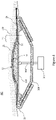
- Fig. 1 shows an example guard plate 10 which is used in a hair cutting appliance for trimming hair, such as a beard trimmer
- Fig. 2 shows a simplified side-view of the geometry of the guard plate 10.
- the guard plate 10 comprises a single integral plate having a skin-facing side 12 and an opposing blade-facing side 14.
- the guard plate 10 comprises a plurality of close-cutting trimming teeth 16 distributed in a longitudinal direction parallel to a longitudinal axis 50 along which the guard plate 10 extends.
- Each close-cutting trimming tooth 16 extends from an edge of the guard plate 10 to a respective tip 20.
- the tooth 16 is bent towards the blade-facing surface 14 (i.e. away from the skin-facing surface 12) and back towards the edge 18 in a bent-back portion at which the teeth 16 join together again to form a continuous plate section.
- the close-cutting teeth 16 are configured to cooperate with cutting teeth 112 on a cutting plate 110 (described in more detail below with reference to Fig. 3 ) to cut hairs.
- the close-cutting trimming teeth 16 have a thickness (of the plate) of approximately 90 microns to ensure that the hair is cut as close as possible to the skin. In other examples, the close-cutting trimming teeth have a thickness of less than 100 microns, or less than 120 microns to ensure a close shave.
- the close-cutting trimming teeth 16 are disposed on opposing edges of the guard plate 10 (i.e. on either side of the longitudinal axis 50) such that the guard plate 10 can be used to cut hairs in two different directions.
- the close-cutting trimming teeth may be disposed only along one edge of the guard plate.
- the guard plate 10 comprises a raised section 22 having a curved shape in a plane which is perpendicular to the longitudinal axis 50 (e.g. the plane shown in Fig. 2 ) and also perpendicular to the edges 18 of the guard plate 10 in this example.
- the raised section 22 is raised from the close-cutting trimming teeth 16 in a direction towards the skin-facing side 12 of the guard plate 10 (i.e. away from the blade-facing side 14).
- the shape of the guard plate in this example is constant along the longitudinal axis 50. In other examples, the shape of the guard plate may vary along the longitudinal axis.
- the guard plate 10 further comprises a pair of pressure relenting zones 30 on either side of the raised section 22, each pressure relenting zone 30 disposed between one set of close-cutting teeth 16 along one edge 18 and the raised section 22.
- each pressure relenting zone 30 comprises a continuous planar section, approximately 1mm long, of the plate between the respective close-cutting teeth 16 and the raised section 22.
- the pressure relenting zone may define any continuous surface, and may be of any suitable length, such as less than 1mm or more than 1mm.
- the pressure relenting zone is at least 0.3mm long to ensure that there is sufficient pressure reduction on the skin in use.
- the raised section 22 has a profile such that it has a height difference of approximately 1mm from the pressure relenting zone 30.
- the raised section 22 is for a foil cutting element and improves the skin contact required for a close shave.
- the raised section may have any suitable height difference from the pressure relenting zone, such as more or less than 1mm, or at least 0.5mm.
- each pressure relenting zone 30 is defined between a respective edge 18 of the guard plate 10 and the respective transition 32.
- the two transitions 32 in this example each comprise a recess with a sharp corner (i.e. a discontinuity).
- the transitions may comprise a recess with a chamfered corner, or a culvert or channel in the otherwise planar or continuous surface from the pressure relenting zone.
- the transition may have any profile which withdraws from a skin-line which a user's skin would follow between the teeth and the raised section in use.
- Each transition 32 ensures that, when the guard plate is passed over the user's taut skin in use, the skin does not directly follow the contours of the plate at the transition 32, such that the pressure on the user's skin applied by the guard plate 10 is reduced locally, or removed altogether, at the transition.
- a pressure relenting line 44 is defined on either side of the raised section 22 by a tangent to the raised section 22 which passes through a respective edge 18 of the guard plate 10 in a plane perpendicular to the longitudinal axis 50 (only one pressure relenting line 44 is shown in Fig. 2 ).
- the raised section 22 comprises a top portion 34 which is adjacent to, and flanked by, two pressure restoring zones 36.
- Each pressure restoring zone 36 is adjacent to a pressure relenting zone 30.
- the pressure restoring zones 36 are each defined between a rising point 38 (within the transition 32) and a tangent point 46 which is on the raised section 22 at the point where the pressure relenting line 44 meets the raised section 22.
- the rising point 38 is defined at the point on the guard plate 10 at which a perpendicular distance (shown by the arrow 40 in Fig. 2 ) between the pressure relenting line 44 and the skin-facing side 12 of the guard plate 10 peaks (i.e. reaches a maximum).
- the change in the perpendicular distance between the pressure relenting line 44 and the skin-facing side 12 of the guard plate 10 in the pressure relenting zone 30 and the pressure restoring zone 36 (referred to herein as the change in height) is 0.1mm.
- the change in height may be more than 0.1mm such as 0.3mm, or more than 0.3mm.
- the peak height at the rising point 38 may be more than 0.1mm, or more than 0.3mm in a preferred example.
- a plurality of apertures 48 are distributed on the raised section 22 on the pressure restoring zones 36 only (best shown in Fig. 1 in which the top portion 34 and the pressure restoring zones 36 are delineated by respective dashed lines indicating the tangent point 46).
- the apertures 48 are configured to capture hairs to be cut.
- the apertures 48 are circular and have a diameter of 300 microns. In other examples, the diameter may extend between a range of 200-400 microns or between 250-350 microns, or may be non-circular and have a dimension of up to 500 microns, and in yet further examples, the apertures may comprise different shapes and sizes.
- the plurality of apertures may be distributed on both the pressure restoring zones and the top portion. Apertures in the pressure restoring zone are more effective at catching hairs than apertures in the top portion, due to the transition to the raised section and the pressure relenting zone.
- the apertures 48 are evenly distributed across the pressure restoring zone 36 and at least within the first 1mm of the pressure restoring zone 36 from the rising point 38. Having the apertures 48 within at least the first 1mm of the pressure restoring zone is also more effective at catching hairs since this is within the first few hair diameters.
- the proportion of apertures 48 to total area of the plate in the pressure restoring zone in this example is approximately 40%. In other examples, the proportion of apertures 48 to total area may be more than 40%. The higher the proportion of apertures in the pressure restoring zone 36, the more likely that hairs will be caught in the apertures 48 for cutting. In other examples, the apertures may not be distributed across the whole of the pressure restoring portion.
- the proportion of apertures to plate material may apply for only the area in which the apertures are located, such as an area bounded by two aperture diameters from the centre of each aperture. It will be appreciated that in some examples, only one pressure restoring zone may comprise apertures.
- the raised section 22 of the guard plate 10 does not extend beyond a raised envelope 24 (shown in Fig. 2 ) to reduce the risk of significantly impeding the cutting ability of the close-cutting teeth 16 when the guard plate 10 is passed over a user's skin in use.
- the raised envelope 24 is defined by a line passing through the edge 18 of the guard plate 10 and offset from a tangent at the edge 18 of the guard plate 10 by an angle, ⁇ , of 30 degrees.
- the tangent at the edge 18 of the guard plate 10 in this example is aligned with the surface of the pressure relenting zone 30 because the pressure relenting zone 30 is planar and extends from the close-cutting teeth 16.
- the angle, ⁇ , of the raised envelope may be 25 degrees. Limiting the raised section 22 to within the raised envelope 24 reduces the negative impacts of the raised section on the performance of the close-cutting trimming teeth 16 which require constant contact with the skin.
- the raised section 22 extends beyond a minimum envelope defined by a line passing through the edge 18 of the guard plate 10 and offset from a tangent at the edge 18 of the guard plate 10 by an angle of 5 degrees (not shown). Having the raised section extend beyond the minimum envelope helps to ensure that there is enough pressure applied to the skin on the raised envelope for the best cutting performance of the raised section.
- the guard plate 10 comprises a single integral plate, in some examples, the guard plate may comprise multiple plates which are fused, or otherwise attached, together.
- the raised section do not extend the entire length along the longitudinal axis of the guard plate, but may be present only in some parts of the guard plate.
- the guard plate 10 has been defined as extending along a longitudinal axis 50, in some examples, it may extend along a curved line such that the guard plate extends with a curvature.
- Fig. 3 shows an exploded view of a blade set 100, comprising the guard plate 10 and a cutting plate 110, which is configured to be received on the guard plate 10 on the blade-facing side 14 of the guard plate 10.
- the cutting plate 110 comprises cutting teeth 112 on opposing edges which are configured to cooperate with the close-cutting trimming teeth 16 on opposing sides of the guard plate 10 to trim hairs.
- the cutting plate 110 further comprises a plurality of blades 114 extending from a face of the cutting plate 110 towards the guard plate 10.
- the blades 114 each have a profile corresponding to the profile of the raised section 22 of the guard plate 10 such that the blades 114 are configured to cooperate with the apertures 48 in the guard plate 10 to cut hairs.
- the blade set 100 in this example further comprises a guard support plate 200 which is configured to be received by the guard plate 10 on the blade-facing side 14, between the close-cutting teeth 16 and the bent back potion of the guard plate 10, so as to support the bent back portion of the guard plate 10, and thereby to support the close-cutting trimming teeth 16.
- the guard support 200 also comprises a plurality of teeth 202 which are configure to align with the close-cutting teeth 16 of the guard plate 10, and which are configured to cooperate with the teeth 112 of the cutting plate 110 to cut hairs.
- the guard support 200 comprises a slot 204 through the thickness of the plate forming the guard support 200.
- the slot 204 extends along a longitudinal direction which is parallel to the longitudinal axis 50 of the guard plate 10 when the blade set 100 is assembled.
- the slot 204 is configured to receive a lever 302 connected to a driving unit 300 (shown in Fig. 4 ).
- the bent-back potion may connect to the blade-facing surface of the guard plate to form a buttress for each close-cutting tooth, instead of having the guard support. Both the guard support and the buttresses reinforce the close-cutting teeth 16, allowing the plate at the close-cutting teeth 16 to be thinner to reliably providing a close shave in use.
- Fig. 4 shows a cutting assembly 400 comprising the blade set 100 and the driving unit 300 being applied to a user's skin.
- the blade set 100 comprises the guard plate 10, the cutting plate 110 and the guard support 200, as is shown being applied to skin 102 to shave or trim the hair on the skin 102, with the skin-facing side 12 of the guard plate 10 running over the skin 102 of a user.
- the driving unit 300 comprises a lever 302 which is received through the slot 204 of the guard support 200 and which is pivotably connected to the cutting plate 110.
- the driving unit 300 is thereby configured to oscillate the cutting plate 110 with respect to the guard plate 10 to cut hair at the close-cutting trimming teeth 16 and at the apertures 48.
- Fig. 4 shows the cutting assembly 400 being passed over a user's skin 102 toward the right side of the page (shown by an arrow).
- the user's skin 102 flows over the guard plate 10 in contact with the close-cutting teeth 16, and over the raised section 22 of the guard plate 10. It can be seen from Fig. 4 that the skin 102 does not follow the contour of the skin-facing side 12 of the guard plate 10 at the pressure relenting zone 30 because of the transition 32 to the raised section 22. Therefore, in the pressure relenting zone 30, there is lower or no pressure on the skin 102 from the guard plate 10.
- the hairs on the skin 102 protrude towards the guard plate 10 and are captured by the apertures 48 in the pressure restoring zone 36 of the raised section 22.
- the apertures must be placed in the pressure restoring zone 36 (i.e. between the rising point and 1mm beyond that point towards the top section 34) so as to be able to capture the hairs from the pressure relenting zone 30 reliably.
- the apertures 48 have been described as being within at least the first 1mm of the raised section 22 from the rising point 38 (i.e. the peak height from the pressure relenting line 44), in some examples, the apertures may be in the first 300 microns of the raised section from the rising point (e.g. within one hair's width from the rising point). The closer the apertures 48 on the raised section 22 are to the rising point 38 of the guard plate 10, the more likely they are to catch the hairs.
- the symmetrical nature of the cutting assembly 400 with the guard plate 10 means that the cutting assembly 400 can be used to cut hairs in either direction.
- the cutting assembly 400 can be mounted on a handle to provide a hair cutting appliance which can be easily manipulated as required by a user.
Abstract
According to an aspect, there is provided a guard plate 10 for a blade set 100 for a hair cutting appliance, the guard plate comprising a skin-facing side 12 and an opposing blade-facing side 14; a plurality of close-cutting trimming teeth 16 distributed in a longitudinal direction along an edge 18 of the guard plate, each tooth extending from the edge of the guard plate to a respective tip 20, the close-cutting trimming teeth having a thickness of less than 120 microns; a raised section 22 comprising a curved shape in a plane perpendicular to the longitudinal direction such that it is raised from the teeth towards the skin-facing side of the guard plate, wherein the curved shape of the raised section does not extend beyond a 30-degree envelope defined by a line passing through the edge of the guard plate and offset from a tangent at the edge of the guard plate by 30 degrees; a pressure relenting zone 30 between the teeth and the raised section defining a continuous surface, wherein there is a transition 32 between the pressure relenting zone and the raised section such that, when the guard plate is passed over a user's taut skin, the skin does not directly follow the contours of the transition thereby locally reducing pressure from the skin; wherein a plurality of apertures 48 are distributed on the raised section at least within a pressure restoring zone of the raised section, the pressure restoring zone being defined between a rising point and a tangent point, wherein the rising point is where a perpendicular distance from the skin-facing surface of the guard plate to a pressure relenting line peaks, wherein the pressure relenting line is defined by a tangent of the raised section in a plane perpendicular to the longitudinal direction, the tangent passing through the edge of the guard plate, and wherein the tangent point is on the raised section at the tangent of the pressure relenting line.
Description
- The invention relates to a guard plate for a blade set for a hair cutting appliance and a blade set, a cutting unit, and hair cutting appliance comprising such a guard plate.
- There are different types of facial hair cutters available, for example trimmers which comprise two sets of oscillating teeth on an edge of a plate, and foil-shavers which comprise a foil with apertures to receive hairs, and a blade to cut the hairs in the apertures. Typically foil-shavers enable a closer shave than trimmers do, but close-cutting trimmers which comprise a very thin plate comprising one set of teeth to lie against the skin can also achieve a very close shave.
- Previously considered arrangements have not successfully combined the foil-shaver and a trimmer in a single unit, because the foil-shaver requires a domed shape for superior cutting performance, but the domed shape interferes with the continuous skin contact required on the teeth of the close-cutting trimmers for a close shave, thereby reducing the performance of the close-cutting trimmers.
-
WO2015158923 discloses a blade set having a curved guard plate comprising trimming teeth and an apertured foil. - According to a first specific aspect, there is provided a guard plate for a blade set for a hair cutting appliance, the guard plate comprising a skin-facing side and an opposing blade-facing side: a plurality of close-cutting trimming teeth distributed in a longitudinal direction along an edge of the guard plate, each tooth extending from the edge of the guard plate to a respective tip, the close-cutting trimming teeth having a thickness of less than 120 microns; a raised section comprising a curved shape in a plane perpendicular to the longitudinal direction such that it is raised from the teeth towards the skin-facing side of the guard plate, wherein the curved shape of the raised section does not extend beyond a 30-degree envelope defined by a line passing through the edge of the guard plate and offset from a tangent at the edge of the guard plate by 30 degrees; a pressure relenting zone between the teeth and the raised section defining a continuous surface, wherein there is a transition between the pressure relenting zone and the raised section such that, when the guard plate is passed over a user's taut skin, the skin does not directly follow the contours of the transition thereby locally reducing pressure from the skin; wherein a plurality of apertures are distributed on the raised section at least within a pressure restoring zone of the raised section, the pressure restoring zone being defined between a rising point and a tangent point, wherein the rising point is where a perpendicular distance from the skin-facing surface of the guard plate to a pressure relenting line peaks, wherein the pressure relenting line is defined by a tangent of the raised section in a plane perpendicular to the longitudinal direction, the tangent passing through the edge of the guard plate, and wherein the tangent point is on the raised section at the tangent of the pressure relenting line.
- The plurality of apertures may be distributed on the raised section at least within the first 1mm of the pressure restoring zone from the rising point.
- The surface of the guard plate at the transition may comprise a change in height of at least 0.1mm, the height being defined by the perpendicular distance between the skin-facing surface and the pressure relenting line.
- The plurality of apertures may be further distributed across a top portion of the raised section adjacent to the pressure restoring zone of the raised section.
- The pressure relenting zone may be planar.
- The guard plate may comprise a plurality of close-cutting trimming teeth distributed in the longitudinal direction along opposing edges of the guard plate. There may be a pair of pressure relenting zones located on either side of the raised section, each pressure relenting zone disposed between the raised section and the teeth along one edge of the guard plate. The raised section may comprise a top portion flanked by two pressure restoring zones, each pressure restoring zone adjacent to a pressure relenting zone, wherein the raised section comprises a plurality of apertures distributed in at least the two pressure restoring zones.
- The guard plate may be formed of a single integral plate.
- The curved shape of the raised section may extend beyond a 5-degree envelope defined by a line passing through the edge of the guard plate and offset from a tangent at the edge of the guard plate by 5 degrees.
- Each tooth may extend from the edge to a tip, and at the tip, each tooth may be bent towards the blade-facing surface and directed back towards the edge, connecting to the blade-facing surface to form a buttress to reinforce the tooth.
- The apertures may be evenly distributed across the pressure restoring zone. The proportion of the area of apertures to total area of the pressure restoring zone may be at least 40%.
- According to a second aspect, there is provided a blade set for a hair cutting appliance comprising the guard plate according to the first aspect, and a cutting plate considered to be received on the guard plate and to cooperate with the guard plate to cut hair.
- According to a third aspect, there is provided a cutting assembly comprising a blade set according to the second aspect, and a driving unit configured to oscillate the cutting plate with respect to the guard plate.
- According to a fourth aspect, there is provided a hair cutting appliance comprising a cutting assembly according to the third aspect mounted on a handle.
- These and other aspects will be apparent from and elucidated with reference to the embodiments described hereinafter.
- Exemplary embodiments will now be described, by way of example only, with reference to the following drawings, in which:
-
Fig. 1 schematically shows a perspective view of an example guard plate; -
Fig. 2 schematically shows a simplified side-view of the example guard plate ofFig. 1 ; -
Fig. 3 schematically shows an exploded view of a blade set comprising the guard plate ofFigs. 1 and2 ; and -
Fig. 4 schematically shows a cross-sectional view of a cutting assembly comprising the blade set ofFig. 3 in use. -
Fig. 1 shows anexample guard plate 10 which is used in a hair cutting appliance for trimming hair, such as a beard trimmer, andFig. 2 shows a simplified side-view of the geometry of theguard plate 10. - The
guard plate 10 comprises a single integral plate having a skin-facingside 12 and an opposing blade-facingside 14. Theguard plate 10 comprises a plurality of close-cutting trimming teeth 16 distributed in a longitudinal direction parallel to alongitudinal axis 50 along which theguard plate 10 extends. - Each close-
cutting trimming tooth 16 extends from an edge of theguard plate 10 to arespective tip 20. At thetip 20 of each close-cutting tooth 16, thetooth 16 is bent towards the blade-facing surface 14 (i.e. away from the skin-facing surface 12) and back towards theedge 18 in a bent-back portion at which theteeth 16 join together again to form a continuous plate section. - The close-
cutting teeth 16 are configured to cooperate withcutting teeth 112 on a cutting plate 110 (described in more detail below with reference toFig. 3 ) to cut hairs. The close-cutting trimming teeth 16 have a thickness (of the plate) of approximately 90 microns to ensure that the hair is cut as close as possible to the skin. In other examples, the close-cutting trimming teeth have a thickness of less than 100 microns, or less than 120 microns to ensure a close shave. - In this example, the close-
cutting trimming teeth 16 are disposed on opposing edges of the guard plate 10 (i.e. on either side of the longitudinal axis 50) such that theguard plate 10 can be used to cut hairs in two different directions. In other examples, the close-cutting trimming teeth may be disposed only along one edge of the guard plate. - The
guard plate 10 comprises a raisedsection 22 having a curved shape in a plane which is perpendicular to the longitudinal axis 50 (e.g. the plane shown inFig. 2 ) and also perpendicular to theedges 18 of theguard plate 10 in this example.. The raisedsection 22 is raised from the close-cutting trimming teeth 16 in a direction towards the skin-facingside 12 of the guard plate 10 (i.e. away from the blade-facing side 14). The shape of the guard plate in this example is constant along thelongitudinal axis 50. In other examples, the shape of the guard plate may vary along the longitudinal axis. - The
guard plate 10 further comprises a pair ofpressure relenting zones 30 on either side of the raisedsection 22, eachpressure relenting zone 30 disposed between one set of close-cutting teeth 16 along oneedge 18 and the raisedsection 22. In this example, eachpressure relenting zone 30 comprises a continuous planar section, approximately 1mm long, of the plate between the respective close-cutting teeth 16 and the raisedsection 22. In other examples, the pressure relenting zone may define any continuous surface, and may be of any suitable length, such as less than 1mm or more than 1mm. In other examples, the pressure relenting zone is at least 0.3mm long to ensure that there is sufficient pressure reduction on the skin in use. - In this example, the raised
section 22 has a profile such that it has a height difference of approximately 1mm from thepressure relenting zone 30. The raisedsection 22 is for a foil cutting element and improves the skin contact required for a close shave. In other examples, the raised section may have any suitable height difference from the pressure relenting zone, such as more or less than 1mm, or at least 0.5mm. - There is a
transition 32 between eachpressure relenting zone 30 and the raisedsection 22, such that eachpressure relenting zone 30 is defined between arespective edge 18 of theguard plate 10 and therespective transition 32. The twotransitions 32 in this example each comprise a recess with a sharp corner (i.e. a discontinuity). In other examples, the transitions may comprise a recess with a chamfered corner, or a culvert or channel in the otherwise planar or continuous surface from the pressure relenting zone. The transition may have any profile which withdraws from a skin-line which a user's skin would follow between the teeth and the raised section in use. - Each
transition 32 ensures that, when the guard plate is passed over the user's taut skin in use, the skin does not directly follow the contours of the plate at thetransition 32, such that the pressure on the user's skin applied by theguard plate 10 is reduced locally, or removed altogether, at the transition. - A
pressure relenting line 44 is defined on either side of the raisedsection 22 by a tangent to the raisedsection 22 which passes through arespective edge 18 of theguard plate 10 in a plane perpendicular to the longitudinal axis 50 (only onepressure relenting line 44 is shown inFig. 2 ). - The raised
section 22 comprises atop portion 34 which is adjacent to, and flanked by, twopressure restoring zones 36. Eachpressure restoring zone 36 is adjacent to apressure relenting zone 30. Thepressure restoring zones 36 are each defined between a rising point 38 (within the transition 32) and atangent point 46 which is on the raisedsection 22 at the point where thepressure relenting line 44 meets the raisedsection 22. The risingpoint 38 is defined at the point on theguard plate 10 at which a perpendicular distance (shown by thearrow 40 inFig. 2 ) between thepressure relenting line 44 and the skin-facingside 12 of theguard plate 10 peaks (i.e. reaches a maximum). In this example, the change in the perpendicular distance between thepressure relenting line 44 and the skin-facingside 12 of theguard plate 10 in thepressure relenting zone 30 and the pressure restoring zone 36 (referred to herein as the change in height) is 0.1mm. In some examples, the change in height may be more than 0.1mm such as 0.3mm, or more than 0.3mm. In other words, the peak height at the risingpoint 38 may be more than 0.1mm, or more than 0.3mm in a preferred example. The larger the change in height at thetransition 32, the more pronounced the effect of thepressure relenting zone 30 will be in reducing the pressure which is applied to the skin locally, because a user's skin will be less likely to be able to follow the contours of the transition when theguard plate 10 is applied and run over the user's skin. Reducing the pressure applied to the skin in this region improves the hair cutting of the raisedsection 22, because the reduction in pressure allows hairs to stick up or reorientate from the user's skin towards theguard plate 10. - A plurality of
apertures 48 are distributed on the raisedsection 22 on thepressure restoring zones 36 only (best shown inFig. 1 in which thetop portion 34 and thepressure restoring zones 36 are delineated by respective dashed lines indicating the tangent point 46). Theapertures 48 are configured to capture hairs to be cut. In this example, theapertures 48 are circular and have a diameter of 300 microns. In other examples, the diameter may extend between a range of 200-400 microns or between 250-350 microns, or may be non-circular and have a dimension of up to 500 microns, and in yet further examples, the apertures may comprise different shapes and sizes. In some examples, the plurality of apertures may be distributed on both the pressure restoring zones and the top portion. Apertures in the pressure restoring zone are more effective at catching hairs than apertures in the top portion, due to the transition to the raised section and the pressure relenting zone. - In this example, the
apertures 48 are evenly distributed across thepressure restoring zone 36 and at least within the first 1mm of thepressure restoring zone 36 from the risingpoint 38. Having theapertures 48 within at least the first 1mm of the pressure restoring zone is also more effective at catching hairs since this is within the first few hair diameters. The proportion ofapertures 48 to total area of the plate in the pressure restoring zone in this example is approximately 40%. In other examples, the proportion ofapertures 48 to total area may be more than 40%. The higher the proportion of apertures in thepressure restoring zone 36, the more likely that hairs will be caught in theapertures 48 for cutting. In other examples, the apertures may not be distributed across the whole of the pressure restoring portion. The proportion of apertures to plate material may apply for only the area in which the apertures are located, such as an area bounded by two aperture diameters from the centre of each aperture. It will be appreciated that in some examples, only one pressure restoring zone may comprise apertures. - The raised
section 22 of theguard plate 10 does not extend beyond a raised envelope 24 (shown inFig. 2 ) to reduce the risk of significantly impeding the cutting ability of the close-cuttingteeth 16 when theguard plate 10 is passed over a user's skin in use. The raisedenvelope 24 is defined by a line passing through theedge 18 of theguard plate 10 and offset from a tangent at theedge 18 of theguard plate 10 by an angle, α, of 30 degrees. The tangent at theedge 18 of theguard plate 10 in this example is aligned with the surface of thepressure relenting zone 30 because thepressure relenting zone 30 is planar and extends from the close-cuttingteeth 16. In some examples, the angle, α, of the raised envelope may be 25 degrees. Limiting the raisedsection 22 to within the raisedenvelope 24 reduces the negative impacts of the raised section on the performance of the close-cuttingtrimming teeth 16 which require constant contact with the skin. - In this example, the raised
section 22 extends beyond a minimum envelope defined by a line passing through theedge 18 of theguard plate 10 and offset from a tangent at theedge 18 of theguard plate 10 by an angle of 5 degrees (not shown). Having the raised section extend beyond the minimum envelope helps to ensure that there is enough pressure applied to the skin on the raised envelope for the best cutting performance of the raised section. - Although it has been described that the
guard plate 10 comprises a single integral plate, in some examples, the guard plate may comprise multiple plates which are fused, or otherwise attached, together. - It will also be appreciated that, in other examples when there is only one set of close-cutting teeth, there may be only a single pressure relenting zone and a raised section, a single transition between the pressure relenting zone and the raised section, and a single pressure restoring zone on the raised section. In some examples, the raised section (and therefore the transition and rising potion) do not extend the entire length along the longitudinal axis of the guard plate, but may be present only in some parts of the guard plate. Further, in some examples, there may be two sets of close-cutting teeth extending along the edges of the guard plate, which may exist in planes offset from one another (i.e. the two edges and sets of teeth may not be in the same plane), in which case the envelopes for the raised section are defined at each respective edge.
- Although, the
guard plate 10 has been defined as extending along alongitudinal axis 50, in some examples, it may extend along a curved line such that the guard plate extends with a curvature. -
Fig. 3 shows an exploded view of ablade set 100, comprising theguard plate 10 and acutting plate 110, which is configured to be received on theguard plate 10 on the blade-facingside 14 of theguard plate 10. - The cutting
plate 110 comprises cuttingteeth 112 on opposing edges which are configured to cooperate with the close-cuttingtrimming teeth 16 on opposing sides of theguard plate 10 to trim hairs. The cuttingplate 110 further comprises a plurality ofblades 114 extending from a face of the cuttingplate 110 towards theguard plate 10. Theblades 114 each have a profile corresponding to the profile of the raisedsection 22 of theguard plate 10 such that theblades 114 are configured to cooperate with theapertures 48 in theguard plate 10 to cut hairs. - The blade set 100 in this example further comprises a
guard support plate 200 which is configured to be received by theguard plate 10 on the blade-facingside 14, between the close-cuttingteeth 16 and the bent back potion of theguard plate 10, so as to support the bent back portion of theguard plate 10, and thereby to support the close-cuttingtrimming teeth 16. Theguard support 200 also comprises a plurality ofteeth 202 which are configure to align with the close-cuttingteeth 16 of theguard plate 10, and which are configured to cooperate with theteeth 112 of the cuttingplate 110 to cut hairs. - The
guard support 200 comprises aslot 204 through the thickness of the plate forming theguard support 200. Theslot 204 extends along a longitudinal direction which is parallel to thelongitudinal axis 50 of theguard plate 10 when the blade set 100 is assembled. Theslot 204 is configured to receive alever 302 connected to a driving unit 300 (shown inFig. 4 ). - In other examples, the bent-back potion may connect to the blade-facing surface of the guard plate to form a buttress for each close-cutting tooth, instead of having the guard support. Both the guard support and the buttresses reinforce the close-cutting
teeth 16, allowing the plate at the close-cuttingteeth 16 to be thinner to reliably providing a close shave in use. -
Fig. 4 shows a cuttingassembly 400 comprising the blade set 100 and thedriving unit 300 being applied to a user's skin. The blade set 100 comprises theguard plate 10, the cuttingplate 110 and theguard support 200, as is shown being applied toskin 102 to shave or trim the hair on theskin 102, with the skin-facingside 12 of theguard plate 10 running over theskin 102 of a user. - The driving
unit 300 comprises alever 302 which is received through theslot 204 of theguard support 200 and which is pivotably connected to thecutting plate 110. The drivingunit 300 is thereby configured to oscillate the cuttingplate 110 with respect to theguard plate 10 to cut hair at the close-cuttingtrimming teeth 16 and at theapertures 48. -
Fig. 4 shows the cuttingassembly 400 being passed over a user'sskin 102 toward the right side of the page (shown by an arrow). The user'sskin 102 flows over theguard plate 10 in contact with the close-cuttingteeth 16, and over the raisedsection 22 of theguard plate 10. It can be seen fromFig. 4 that theskin 102 does not follow the contour of the skin-facingside 12 of theguard plate 10 at thepressure relenting zone 30 because of thetransition 32 to the raisedsection 22. Therefore, in thepressure relenting zone 30, there is lower or no pressure on theskin 102 from theguard plate 10. Due to the lower, or absence of, pressure in thepressure relenting zone 30, the hairs on theskin 102 protrude towards theguard plate 10 and are captured by theapertures 48 in thepressure restoring zone 36 of the raisedsection 22. The apertures must be placed in the pressure restoring zone 36 (i.e. between the rising point and 1mm beyond that point towards the top section 34) so as to be able to capture the hairs from thepressure relenting zone 30 reliably. - Although the
apertures 48 have been described as being within at least the first 1mm of the raisedsection 22 from the rising point 38 (i.e. the peak height from the pressure relenting line 44), in some examples, the apertures may be in the first 300 microns of the raised section from the rising point (e.g. within one hair's width from the rising point). The closer theapertures 48 on the raisedsection 22 are to the risingpoint 38 of theguard plate 10, the more likely they are to catch the hairs. - The symmetrical nature of the cutting
assembly 400 with theguard plate 10 means that the cuttingassembly 400 can be used to cut hairs in either direction. - The cutting
assembly 400 can be mounted on a handle to provide a hair cutting appliance which can be easily manipulated as required by a user. - Variations to the disclosed embodiments can be understood and effected by those skilled in the art in practicing the principles and techniques described herein, from a study of the drawings, the disclosure and the appended claims. In the claims, the word "comprising" does not exclude other elements or steps, and the indefinite article "a" or "an" does not exclude a plurality. The mere fact that certain measures are recited in mutually different dependent claims does not indicate that a combination of these measures cannot be used to advantage. Any reference signs in the claims should not be construed as limiting the scope.
Claims (14)
- A guard plate (10) for a blade set (100) for a hair cutting appliance, the guard plate (10) comprising a skin-facing side (12) and an opposing blade-facing side (14):a plurality of close-cutting trimming teeth (16) distributed in a longitudinal direction along an edge (18) of the guard plate (10), each tooth extending from the edge (18) of the guard plate (10) to a respective tip, the close-cutting trimming teeth (16) having a thickness of less than 120 microns;a raised section (22) comprising a curved shape in a plane perpendicular to the longitudinal direction such that it is raised from the teeth (16) towards the skin-facing side (12) of the guard plate (10), wherein the curved shape of the raised section (22) does not extend beyond a 30-degree envelope defined by a line passing through the edge (18) of the guard plate (10) and offset from a tangent at the edge (18) of the guard plate by 30 degrees;a pressure relenting zone (30) between the teeth (20) and the raised section (22) defining a continuous surface, wherein there is a transition (32) between the pressure relenting zone (30) and the raised section (22) such that, when the guard plate (10) is passed over a user's taut skin (102), the skin (102) does not directly follow the contours of the transition (32) thereby locally reducing pressure from the skin (102);wherein a plurality of apertures (48) are distributed on the raised section (22) at least within a pressure restoring zone (36) of the raised section (22), the pressure restoring zone (36) being defined between a rising point (38) and a tangent point (46), wherein the rising point (38) is where a perpendicular distance from the skin-facing surface (12) of the guard plate (10) to a pressure relenting line (44) peaks, wherein the pressure relenting line (44) is defined by a tangent of the raised section (22) in a plane perpendicular to the longitudinal direction, the tangent passing through the edge (18) of the guard plate (10), and wherein the tangent point (46) is on the raised section (22) at the tangent of the pressure relenting line (44).
- A guard plate (10) according to claim 1, wherein the plurality of apertures (48) are distributed on the raised section (22) at least within the first 1mm of the pressure restoring zone (36) from the rising point (38).
- A guard plate (10) according to claim 1, wherein the surface of the guard plate (10) at the transition (32) comprises a change in height of at least 0.1mm, the height being defined by the perpendicular distance between the skin-facing surface and the pressure relenting line (44).
- A guard plate (10) according to any preceding claim, wherein the plurality of apertures (48) are further distributed across a top portion (34) of the raised section (22) adjacent to the pressure restoring zone (36) of the raised section (22).
- A guard plate (10) according to any preceding claim, wherein the pressure relenting zone (30) is planar.
- A guard plate (10) according to any preceding claim, wherein the guard plate (10) comprises a plurality of close-cutting trimming teeth (16) distributed in the longitudinal direction along opposing edges (18) of the guard plate (10);
wherein there are a pair of pressure relenting zones (30) located on either side of the raised section (22), each pressure relenting zone (30) disposed between the raised section (22) and the teeth (16) along one edge (18) of the guard plate (10); and
wherein the raised section (22) comprises a top portion (34) flanked by two pressure restoring zones (36), each pressure restoring zone (36) adjacent to a pressure relenting zone (30), wherein the raised section (22) comprises a plurality of apertures (48) distributed in at least the two pressure restoring zones (36). - A guard plate (10) according to any preceding claim, wherein the guard plate (10) is formed of a single integral plate.
- A guard plate (10) according to any preceding claim, wherein the curved shape of the raised section (22) extends beyond a 5-degree envelope defined by a line passing through the edge (18) of the guard plate (10) and offset from a tangent at the edge (18) of the guard plate by 5 degrees.
- A guard plate (10) according to any preceding claim, wherein each tooth extends from the edge (18) to a tip, and at the tip, each tooth is bent towards the blade-facing surface and directed back towards the edge (18), connecting to the blade-facing surface to form a buttress to reinforce the tooth.
- A guard plate (10) according to any preceding claim, wherein the apertures (48) are evenly distributed across the pressure restoring zone (36).
- A guard plate (10) according to any preceding claim, wherein the proportion of the area of apertures (48) to total area of the pressure restoring zone (36) is at least 40%.
- A blade set (100) for a hair cutting appliance comprising the guard plate (10) according to any preceding claim and a cutting plate (110) considered to be received on the guard plate (10) and to cooperate with the guard plate (10) to cut hair.
- A cutting assembly (400) comprising a blade set (100) according to claim 12 and a driving unit (300) configured to oscillate the cutting plate (110) with respect to the guard plate (10).
- A hair cutting appliance comprising a cutting assembly (400) according to claim 13 mounted on a handle.
Priority Applications (4)
| Application Number | Priority Date | Filing Date | Title |
|---|---|---|---|
| EP21185741.2A EP4119310A1 (en) | 2021-07-15 | 2021-07-15 | A guard plate |
| PCT/EP2022/069630 WO2023285546A1 (en) | 2021-07-15 | 2022-07-13 | A guard plate |
| CN202221823710.0U CN218802405U (en) | 2021-07-15 | 2022-07-14 | Guard plate, blade set, cutting assembly and hair cutting appliance |
| CN202210831849.8A CN115609641A (en) | 2021-07-15 | 2022-07-14 | Protective plate |
Applications Claiming Priority (1)
| Application Number | Priority Date | Filing Date | Title |
|---|---|---|---|
| EP21185741.2A EP4119310A1 (en) | 2021-07-15 | 2021-07-15 | A guard plate |
Publications (1)
| Publication Number | Publication Date |
|---|---|
| EP4119310A1 true EP4119310A1 (en) | 2023-01-18 |
Family
ID=76942850
Family Applications (1)
| Application Number | Title | Priority Date | Filing Date |
|---|---|---|---|
| EP21185741.2A Withdrawn EP4119310A1 (en) | 2021-07-15 | 2021-07-15 | A guard plate |
Country Status (3)
| Country | Link |
|---|---|
| EP (1) | EP4119310A1 (en) |
| CN (2) | CN218802405U (en) |
| WO (1) | WO2023285546A1 (en) |
Citations (7)
| Publication number | Priority date | Publication date | Assignee | Title |
|---|---|---|---|---|
| CH191063A (en) * | 1937-04-17 | 1937-05-31 | Brunner Walter | Electric dry shaving machine. |
| US2102529A (en) * | 1935-02-07 | 1937-12-14 | Clipshave Inc | Hair clipper |
| US2151965A (en) * | 1937-04-05 | 1939-03-28 | Clipshave Inc | Hair clipper |
| CH229244A (en) * | 1942-05-16 | 1943-10-15 | Affolter Andre | A method of manufacturing a mechanical razor guard and guard made by this process. |
| WO2015158923A1 (en) | 2014-04-18 | 2015-10-22 | Koninklijke Philips N.V. | Blade set, hair cutting appliance, and related manufacturing method |
| US20180257248A1 (en) * | 2016-10-12 | 2018-09-13 | Rangpan Wu | Reciprocating Electric Razor Head |
| WO2019110335A1 (en) * | 2017-12-05 | 2019-06-13 | Koninklijke Philips N.V. | Shaving assembly and hair cutting appliance |
-
2021
- 2021-07-15 EP EP21185741.2A patent/EP4119310A1/en not_active Withdrawn
-
2022
- 2022-07-13 WO PCT/EP2022/069630 patent/WO2023285546A1/en active Application Filing
- 2022-07-14 CN CN202221823710.0U patent/CN218802405U/en active Active
- 2022-07-14 CN CN202210831849.8A patent/CN115609641A/en active Pending
Patent Citations (7)
| Publication number | Priority date | Publication date | Assignee | Title |
|---|---|---|---|---|
| US2102529A (en) * | 1935-02-07 | 1937-12-14 | Clipshave Inc | Hair clipper |
| US2151965A (en) * | 1937-04-05 | 1939-03-28 | Clipshave Inc | Hair clipper |
| CH191063A (en) * | 1937-04-17 | 1937-05-31 | Brunner Walter | Electric dry shaving machine. |
| CH229244A (en) * | 1942-05-16 | 1943-10-15 | Affolter Andre | A method of manufacturing a mechanical razor guard and guard made by this process. |
| WO2015158923A1 (en) | 2014-04-18 | 2015-10-22 | Koninklijke Philips N.V. | Blade set, hair cutting appliance, and related manufacturing method |
| US20180257248A1 (en) * | 2016-10-12 | 2018-09-13 | Rangpan Wu | Reciprocating Electric Razor Head |
| WO2019110335A1 (en) * | 2017-12-05 | 2019-06-13 | Koninklijke Philips N.V. | Shaving assembly and hair cutting appliance |
Also Published As
| Publication number | Publication date |
|---|---|
| CN115609641A (en) | 2023-01-17 |
| WO2023285546A1 (en) | 2023-01-19 |
| CN218802405U (en) | 2023-04-07 |
Similar Documents
| Publication | Publication Date | Title |
|---|---|---|
| US11577413B2 (en) | Electric handheld hair trimmer including blade with beveled portions | |
| AU2017327812B2 (en) | Bidirectional shaving device | |
| JP4463804B2 (en) | Razor cartridge | |
| AU2006258078B2 (en) | Inter-blade guard and method for manufacturing same | |
| EP1597028B1 (en) | Multiple blade razor cartridge | |
| EP2537648A1 (en) | Razor cartridge with skin contact element | |
| KR102180992B1 (en) | A shaving blade cartridge, a shaver comprising such shaving blade cartridge and a method of manufacturing such a shaving blade cartridge | |
| US20100071215A1 (en) | Trimmer for shaving razor | |
| CN113618789B (en) | Electric beard trimmer | |
| KR20090120521A (en) | Razor cartridge pivot axis | |
| KR20070015143A (en) | Saving razor with additional trimming blade | |
| KR19990067406A (en) | Oval frame shaver | |
| US20210129364A1 (en) | Guard for hair removal device | |
| US5504997A (en) | Blade holder assembly for an electric razor | |
| KR960705663A (en) | Multi-Blade Razor Head with Improved Performance | |
| EP4119310A1 (en) | A guard plate | |
| EP1011934B1 (en) | Razor blade and cartridge including same | |
| US20170239826A1 (en) | Manual Razor Having Diagonally Positioned Blades | |
| US20230166416A1 (en) | Razor Cartridge Seal | |
| JPS5937985B2 (en) | reciprocating electric razor blades |
Legal Events
| Date | Code | Title | Description |
|---|---|---|---|
| PUAI | Public reference made under article 153(3) epc to a published international application that has entered the european phase |
Free format text: ORIGINAL CODE: 0009012 |
|
| STAA | Information on the status of an ep patent application or granted ep patent |
Free format text: STATUS: THE APPLICATION HAS BEEN PUBLISHED |
|
| AK | Designated contracting states |
Kind code of ref document: A1 Designated state(s): AL AT BE BG CH CY CZ DE DK EE ES FI FR GB GR HR HU IE IS IT LI LT LU LV MC MK MT NL NO PL PT RO RS SE SI SK SM TR |
|
| STAA | Information on the status of an ep patent application or granted ep patent |
Free format text: STATUS: THE APPLICATION IS DEEMED TO BE WITHDRAWN |
|
| 18D | Application deemed to be withdrawn |
Effective date: 20230719 |