EP4119288A1 - Vorrichtung zur korrektur von positionsabweichungen einer bearbeitungsmaschine - Google Patents
Vorrichtung zur korrektur von positionsabweichungen einer bearbeitungsmaschine Download PDFInfo
- Publication number
- EP4119288A1 EP4119288A1 EP22168306.3A EP22168306A EP4119288A1 EP 4119288 A1 EP4119288 A1 EP 4119288A1 EP 22168306 A EP22168306 A EP 22168306A EP 4119288 A1 EP4119288 A1 EP 4119288A1
- Authority
- EP
- European Patent Office
- Prior art keywords
- axis
- actuator
- rotation
- measuring device
- group
- Prior art date
- Legal status (The legal status is an assumption and is not a legal conclusion. Google has not performed a legal analysis and makes no representation as to the accuracy of the status listed.)
- Granted
Links
Images


Classifications
-
- G—PHYSICS
- G05—CONTROLLING; REGULATING
- G05B—CONTROL OR REGULATING SYSTEMS IN GENERAL; FUNCTIONAL ELEMENTS OF SUCH SYSTEMS; MONITORING OR TESTING ARRANGEMENTS FOR SUCH SYSTEMS OR ELEMENTS
- G05B19/00—Program-control systems
- G05B19/02—Program-control systems electric
- G05B19/18—Numerical control [NC], i.e. automatically operating machines, in particular machine tools, e.g. in a manufacturing environment, so as to execute positioning, movement or co-ordinated operations by means of program data in numerical form
- G05B19/19—Numerical control [NC], i.e. automatically operating machines, in particular machine tools, e.g. in a manufacturing environment, so as to execute positioning, movement or co-ordinated operations by means of program data in numerical form characterised by positioning or contouring control systems, e.g. to control position from one programmed point to another or to control movement along a programmed continuous path
-
- B—PERFORMING OPERATIONS; TRANSPORTING
- B23—MACHINE TOOLS; METAL-WORKING NOT OTHERWISE PROVIDED FOR
- B23Q—DETAILS, COMPONENTS, OR ACCESSORIES FOR MACHINE TOOLS, e.g. ARRANGEMENTS FOR COPYING OR CONTROLLING; MACHINE TOOLS IN GENERAL CHARACTERISED BY THE CONSTRUCTION OF PARTICULAR DETAILS OR COMPONENTS; COMBINATIONS OR ASSOCIATIONS OF METAL-WORKING MACHINES, NOT DIRECTED TO A PARTICULAR RESULT
- B23Q17/00—Arrangements for observing, indicating or measuring on machine tools
- B23Q17/22—Arrangements for observing, indicating or measuring on machine tools for indicating or measuring existing or desired position of tool or work
- B23Q17/2291—Arrangements for observing, indicating or measuring on machine tools for indicating or measuring existing or desired position of tool or work for adjusting the workpiece relative to the holder thereof
-
- B—PERFORMING OPERATIONS; TRANSPORTING
- B23—MACHINE TOOLS; METAL-WORKING NOT OTHERWISE PROVIDED FOR
- B23Q—DETAILS, COMPONENTS, OR ACCESSORIES FOR MACHINE TOOLS, e.g. ARRANGEMENTS FOR COPYING OR CONTROLLING; MACHINE TOOLS IN GENERAL CHARACTERISED BY THE CONSTRUCTION OF PARTICULAR DETAILS OR COMPONENTS; COMBINATIONS OR ASSOCIATIONS OF METAL-WORKING MACHINES, NOT DIRECTED TO A PARTICULAR RESULT
- B23Q1/00—Members which are comprised in the general build-up of a form of machine, particularly relatively large fixed members
- B23Q1/25—Movable or adjustable work or tool supports
- B23Q1/44—Movable or adjustable work or tool supports using particular mechanisms
- B23Q1/50—Movable or adjustable work or tool supports using particular mechanisms with rotating pairs only, the rotating pairs being the first two elements of the mechanism
- B23Q1/52—Movable or adjustable work or tool supports using particular mechanisms with rotating pairs only, the rotating pairs being the first two elements of the mechanism a single rotating pair
- B23Q1/525—Movable or adjustable work or tool supports using particular mechanisms with rotating pairs only, the rotating pairs being the first two elements of the mechanism a single rotating pair which is parallel to the working surface
-
- B—PERFORMING OPERATIONS; TRANSPORTING
- B23—MACHINE TOOLS; METAL-WORKING NOT OTHERWISE PROVIDED FOR
- B23Q—DETAILS, COMPONENTS, OR ACCESSORIES FOR MACHINE TOOLS, e.g. ARRANGEMENTS FOR COPYING OR CONTROLLING; MACHINE TOOLS IN GENERAL CHARACTERISED BY THE CONSTRUCTION OF PARTICULAR DETAILS OR COMPONENTS; COMBINATIONS OR ASSOCIATIONS OF METAL-WORKING MACHINES, NOT DIRECTED TO A PARTICULAR RESULT
- B23Q17/00—Arrangements for observing, indicating or measuring on machine tools
- B23Q2017/001—Measurement or correction of run-out or eccentricity
-
- B—PERFORMING OPERATIONS; TRANSPORTING
- B23—MACHINE TOOLS; METAL-WORKING NOT OTHERWISE PROVIDED FOR
- B23Q—DETAILS, COMPONENTS, OR ACCESSORIES FOR MACHINE TOOLS, e.g. ARRANGEMENTS FOR COPYING OR CONTROLLING; MACHINE TOOLS IN GENERAL CHARACTERISED BY THE CONSTRUCTION OF PARTICULAR DETAILS OR COMPONENTS; COMBINATIONS OR ASSOCIATIONS OF METAL-WORKING MACHINES, NOT DIRECTED TO A PARTICULAR RESULT
- B23Q2220/00—Machine tool components
- B23Q2220/004—Rotary tables
-
- B—PERFORMING OPERATIONS; TRANSPORTING
- B23—MACHINE TOOLS; METAL-WORKING NOT OTHERWISE PROVIDED FOR
- B23Q—DETAILS, COMPONENTS, OR ACCESSORIES FOR MACHINE TOOLS, e.g. ARRANGEMENTS FOR COPYING OR CONTROLLING; MACHINE TOOLS IN GENERAL CHARACTERISED BY THE CONSTRUCTION OF PARTICULAR DETAILS OR COMPONENTS; COMBINATIONS OR ASSOCIATIONS OF METAL-WORKING MACHINES, NOT DIRECTED TO A PARTICULAR RESULT
- B23Q2220/00—Machine tool components
- B23Q2220/006—Spindle heads
Definitions
- the invention relates to a device comprising a measuring device, a control device, an actuator and a controller according to claim 1.
- a relative movement of a tool to the workpiece is controlled by a controller with the aid of drives.
- the tool is often fixed in a spindle and the workpiece is mounted on a swiveling rotary table.
- Spindles or motor spindles often hold a rotating tool, for example a milling cutter, particularly in machine tools.
- Workpieces are fastened to the swiveling rotary tables, which are then machined, for example.
- Such spindles or rotary tables are often equipped with angle measuring devices that are used to measure the rotary movements of a shaft. Angle measuring devices are used in particular for processing machines used to measure rotational movements.
- the object of the invention is to create a device that makes it possible to increase the positioning accuracy of a machine tool during ongoing operation.
- the device which is suitable for correcting position deviations between a tool holder and a workpiece holder of a processing machine, comprises a measuring device, a regulating device, an actuator and a controller.
- the measuring device comprises a first group of components and a second group of components, the first group of components and the second group of components being rotatable relative to one another about an axis of rotation.
- the first component group can be fastened to a stationary structure of the processing machine and is therefore arranged stationary with respect to a Cartesian coordinate system with a first directional axis, a second directional axis and a third directional axis.
- the second group of components can be fastened to a component that can be rotated or pivoted about the axis of rotation, so that when the processing machine is at rest, the axis of rotation in the Cartesian coordinate system runs parallel to the first directional axis when the system is perfectly set up.
- the Measuring device is a measurement of the relative position between the first component group and the second component group in several dimensions, so in several degrees of freedom (z. B. six) of the movements in space, feasible.
- the measuring device can generate first signals under operating load of the processing machine, which contain information about the actual orientation of the axis of rotation relative to the first directional axis.
- the measuring device can generate second signals under operating load of the processing machine, which contain information about the actual translatory position of the first component group relative to the second component group in the first directional axis and/or in the second directional axis and/or in the third directional axis.
- the measuring device is connected to the control device for transmission of the first signals.
- the actuator can be mounted on the component in such a way that the orientation of the axis of rotation relative to the first component group can be changed by actuating the actuator.
- the control device is configured in such a way that, depending on the information on the actual orientation of the axis of rotation relative to the first directional axis, the axis of rotation can be brought into a desired orientation with the aid of the actuator.
- the measuring device is connected to the controller for the transmission of the second signals, so that the relative position between the tool holder and the workpiece holder can be corrected with the aid of drives.
- the actuator can have exactly one actuator, for example.
- Such an arrangement is particularly advantageous with regard to minimizing the construction effort when the orientation of the axis of rotation is decisively or dominantly influenced by a weight (eg of the workpiece).
- one actuator would be variable in length in the vertical direction.
- the actuator advantageously comprises at least two actuators or three actuators, which are then arranged in a star shape.
- the actuator comprises at least one actuator and a bearing, in particular a roller bearing, wherein the at least one actuator on the bearing, in particular on its outer ring, attacks, so that the Actuating forces act on the bearing.
- the bearing in particular its inner ring, can preferably be mounted on the rotatable component.
- the actuator comprises at least one actuator whose function is based on the piezo effect.
- the actuator can also have an actuator that works according to a hydraulic principle or that is designed as a wedge mechanism.
- an electrically driven actuator can optionally be used. It is generally advantageous if the control element has at least one actuator whose function is based on an electromechanical principle.
- control device and the actuator can be configured in such a way that they also dampen or suppress oscillations or vibrations, such as can occur during the machining of workpieces, such as chattering oscillations. In this way, in particular, the quality of the machined surfaces of the workpiece can be improved.
- the measuring device can measure the angular position between the first component group and the second component group and angular position signals can be generated which contain information about the angular position, the measuring device being connected to the controller for transmitting the angular position signals.
- the measuring device advantageously comprises at least two first position sensors, at least two second position sensors and a scale element which has a first division or a first scale and a second division or a second scale.
- the scale element is arranged to be rotatable about the axis of rotation relative to the first and second position sensors.
- the first partition comprises regular structures which are arranged in a row parallel to one another along a first direction, the first direction having a directional component in the circumferential direction.
- the second partition comprises regular structures which are arranged in a row along the first directional axis x parallel to one another, with the first directional axis x having a directional component has in the axial direction.
- the at least two first position sensors are offset from one another in the circumferential direction, with the at least two first position sensors being able to scan the first graduation, so that the position of the scale element in a plane oriented perpendicular to the axis of rotation can be determined (and thus the position of the Axis of rotation or axis displacement under operating load).
- an angular position of the scale element in relation to the first position sensors ie relative to the position sensors
- the at least two second position sensors are also arranged offset from one another in the circumferential direction, the second graduation being scannable by the second position sensors and the axial position of the scale element (and thus an axis displacement in the axial direction under operating load) being determinable.
- axial or “axial direction” is to be understood below as meaning a direction parallel to the axis of rotation.
- An angular position of the scale element in relation to the first position sensor can be absolutely determined within one revolution by at least one of the first position sensors. This can be achieved, for example, by the first graduation having an absolute code track or by a reference mark being applied to the scale element, which, in conjunction with an incremental graduation, permits an absolute determination of the angular position within one revolution.
- the first direction along which the regular structures of the first division are arranged in a row, can be identical to the circumferential direction.
- the first direction can be inclined or arranged at an angle to the circumferential direction (but not perpendicular to the circumferential direction).
- the second direction along which the regular structures of the second division are arranged in a row, can be arranged identically to the axial direction (and thus parallel to the axis of rotation).
- the second direction can be inclined or arranged at an angle to the axial direction (but not perpendicular to the axial direction Direction).
- regular structures of the first division and those of the second division can be oriented in the shape of arrows relative to one another.
- the measuring device advantageously has at least three first position sensors and at least three second position sensors.
- a tilting of the scale element and thus a tilting or orientation of the axis of rotation can advantageously be determined by the second position sensors.
- at least the second position sensors can be electrically connected to an electronic component, the tilting of the scale element being able to be determined by the electronic component. It is particularly advantageous here if three or more second position sensors are used.
- Processing machines are naturally designed to be correspondingly rigid, which is why such tilting or deviations of the axis of rotation from the target orientation are comparatively small and range from less than one angular minute relative to the ideal axis of rotation, for example 100 angular seconds down to 50 angular seconds. Consequently, due to these deviations of the axis of rotation from the target orientation, there are also only minimal changes in position, so that the measuring device must have a very high resolution in order to be able to provide reliable statements or quantitative values with regard to the tilting.
- the described deviations of the axis of rotation from the target orientation can lead to wobbling movements of the scale element, with the wobbling movements being able to be recorded quantitatively by the measuring device, in particular by adding the measured angular position.
- the first position sensors and/or the second position sensors are designed as optical sensors and the structures of the first graduation and/or the second graduation as light-modulating structures.
- the measuring device can also have position sensors that are based on a magnetic or inductive measuring principle, with combinations of the principles also being possible so that the first pitch can be scanned according to a different principle than the second pitch.
- the measuring device can advantageously have a resolution of less than 2 ⁇ m, in particular less than 1 ⁇ m, in particular less than 750 nm. These values for the resolutions can be used both for determining the axial and the lateral positions, i.e. in the plane perpendicular to the axis of rotation can be achieved.
- the sensors of the first position pickups are offset relative to the sensors of the second position pickups, by which the second graduation can be scanned, with respect to the axial direction.
- At least the second graduation (or both graduations) is advantageously applied to a lateral side of a cylindrical scale element.
- a ring-shaped body for example, which can be attached to a rotatable component, comes into consideration as the scale element.
- the first and/or the second graduation can also be applied directly to the rotatable component.
- FIG. 1 a basic structure of a processing machine is shown, which is suitable, for example, for milling.
- the processing machine includes a stationary structure S, to which a stationary Cartesian coordinate system with a first directional axis x, a second directional axis y and a third directional axis z can be assigned.
- a workpiece holder W or a rotary table is arranged so as to be rotatable relative to the stationary structure S about an axis of rotation A, which is oriented parallel to the first directional axis x.
- the processing machine has a tool holder T in which a milling tool can be fixed.
- the tool holder T can be moved laterally or transversely relative to the fixed structure S, in accordance with the double arrows in FIG figure 1 in the first directional axis x, the second directional axis y and the third directional axis z.
- the figure 2 shows a detailed view of the processing machine, in particular the workpiece holder W and the associated drive, which has a component R rotatable about the axis of rotation A, here a rotor of an electric motor.
- the processing machine also has a measuring device 1 .
- the measuring device 1 comprises a first group of components 1.1 and a second group of components 1.2.
- the first group of components 1.1 is fixed to the stationary structure S and the second group of components 1.2 to the rotatable component R. Accordingly, the second group of components 1.2 can be rotated about the axis of rotation A relative to the first group of components 1.1, so that the first group of components 1.1 can then function as a stator and the second group of components 1.2 can also be referred to as a rotor.
- the second component group 1.2 has a scale element 1.21, for example a drum, which is fixed to the rotatable component R in a rotationally fixed manner.
- the scale element 1.21 is ring-shaped here and encloses the rotatable component R. After assembly, the scale element 1.21 is rigidly and non-rotatably connected to the rotatable component R. A scale 1.22 or a graduation is applied to the shell of the scale element 1.21.
- the scale element 1.21 is designed as a cylindrical or ring-shaped body, on the lateral side of which according to FIG figure 4 a scale 1.22 is applied.
- This comprises a first division 1.221 and a second division 1.222, the second division 1.222 being offset relative to the first division 1.221 with respect to the first directional axis x.
- the first division 1.221 comprises regular structures or lines, which are arranged in a row in parallel along the circumferential direction u offset to one another.
- the first graduation 1.221 includes a reference mark 1.223.
- the second graduation 1.222 includes regular structures or lines that are arranged in a row along the first direction axis x parallel to one another.
- the structures of the first graduation 1.221, the second graduation 1.222 and the reference mark 1.223 are designed in the exemplary embodiment presented as light-reflecting and non-reflecting strips.
- the measuring device 1 has three first position sensors 1.11, 1.13, 1.15 and three second position sensors 1.12, 1.14, 1.16.
- the position sensors 1.11, 1.12, 1.13, 1.14, 1.15, 1.16 are arranged offset to one another in the circumferential direction u and are arranged opposite the scale element 1.21 with a radial air gap, in particular along a circular line.
- each position sensor 1.11, 1.12, 1.13, 1.14, 1.15, 1.16 in the exemplary embodiment presented has a housing in which corresponding photosensitive sensor elements are arranged.
- the housing can also be dispensed with, or a plurality of sensor elements can also be arranged in one and the same housing.
- several or all position sensors 1.11, 1.12, 1.13, 1.14, 1.15, 1.16 can also be mounted on one and the same circuit board.
- an actuator 3 is mounted on the rotatable component R. This is located at the other end of the rotatable component R with respect to the measuring device 1 , so that the winding of the drive is arranged between the measuring device 1 and the actuator 3 .
- the actuator 3 includes in the presented embodiment according to figure 5 three actuators 3.1, 3.2, 3.3, which are offset by 120 ° arranged in a star shape.
- the radially outer ends of the actuators 3.1, 3.2, 3.3 are fastened to the stationary structure S and are connected to a bearing 3.4 radially on the inside.
- the bearing 3.4 is designed as a roller bearing, the inner ring of which is fastened to the rotatable component R.
- the actuators 3.1, 3.2, 3.3 are variable in length. In the exemplary embodiment presented, the change in length is achieved by a piezo principle.
- the actuators 3.1, 3.2, 3.3 or the actuating forces generated by the actuators 3.1, 3.2, 3.3 act on the bearing 3.4, in particular on the outer ring of the bearing 3.4. Consequently, the actuator 3 is mounted on the rotatable component R in such a way that by actuating the actuator 3 the orientation of the axis of rotation A can be changed relative to the first component group 1.1.
- the scale element 1.21 Due to its first graduation 1.221, the scale element 1.21 is able to modulate the incident light according to the angular position of the scale element 1.21.
- the incident light is modulated by the second division 1.222 in accordance with the axial position of the scale element 1.21 or the rotatable component R.
- the modulated light hits the sensor elements of the position sensors 1.11, 1.12, 1.13, 1.14, 1.15, 1.16.
- the first graduation 1.221 can be scanned by the first position sensors 1.11, 1.13, 1.15 in such a way that the first position sensors 1.11, 1.13, 1.15 an angular position of the scale element 1.21 in relation to the first position sensors 1.11, 1.13, 1.15 can be determined.
- the angular position can be absolutely determined within one revolution.
- an incremental first division 1.221 can be used, through which, in conjunction with the reference mark 1.223, an absolute angular position can be generated over one revolution.
- the first division 1.221 can be designed absolutely, for example as a pseudo-random code or Gray code, in the sense of a coding, ie with the generation of a unique code value.
- the signals from the first position sensors 1.11, 1.13, 1.15 are routed to an electronic circuit, where in particular digital values of the angular position are generated.
- the position of the scale element 1.21 in a plane P which is oriented perpendicularly to the axis of rotation A, can be determined, i.e. the yz coordinates of the actual position of the axis of rotation A.
- This position which can also be referred to as the lateral position, for the given workpiece holder W depends on the load during machining.
- the absolute angular position of the rotatable component R is also assigned to the current lateral position.
- the second position sensors 1.12, 1.14, 1.16 are electrically connected to the electronic circuit.
- the second position sensors 1.12, 1.14, 1.16 are used to scan the second graduation 1.222, with the second position sensors 1.12, 1.14, 1.16 being able to determine the axial position or the orientation of the scale element 1.21.
- the absolute angular position of the rotatable component R is also assigned to the axial position.
- the measuring device 1 can measure the relative position between the first component group 1.1 and the second component group 1.2 in several dimensions; in particular, eccentricities, wobbling movements or axial displacements of the rotatable component R relative to the stationary structure S are determined.
- the device makes it possible, especially for rotary tables, depending on the absolute angular position of the rotatable component R to measure the lateral and axial position. Due to the fact that rotary tables are already very rigidly constructed, position measurements are carried out here that are in the ⁇ m range or less. The (actual) orientation of the axis of rotation A relative to the stationary structure S is also measured. For this purpose too, a high resolution, in particular of the second position sensors 1.12, 1.14, 1.16, is required.
- FIG 6 is a simplified basic arrangement of a device for correcting positional deviations between a tool holder T and a workpiece holder W of a machine tool, which as indicated by the dash-dotted delimitation in FIG figure 6 shown, the measuring device 1, a control device 2, the actuator 3 and a controller 4 comprises.
- the measuring device 1 can generate first signals S1 during operation of the processing machine, which contain information about the current actual orientation of the axis of rotation A relative to the first directional axis x, i.e. information about the tilting of the axis of rotation A.
- the measuring device 1 is connected to the control device 2, for example via a cable.
- the incoming information about the orientation of the axis of rotation A, ie the actual position of the axis of rotation A in space, is supplied to the control device 2 by the first signals S1.
- the deviation of the orientation of the axis of rotation A from the orientation of the first directional axis x is determined in magnitude and direction.
- the axis of rotation A is pushed in one direction by actuating the actuator 3, here the three actuators 3.1, 3.2, 3.3, so that the axis of rotation A is aligned parallel to the first directional axis x within predefined tolerances, i.e. brought into the desired orientation.
- Disturbances that are responsible for the fact that the orientation of the axis of rotation A tilts relative to the first directional axis x are, for example, weight forces of the workpiece, deflection forces of the tool during processing or chatter vibrations into consideration. Now, when the controller operates, the tool is oriented at the correct angle relative to the workpiece.
- the measuring device generates second signals S2, which contain information about the actual translatory position of the first component group 1.1 relative to the second component group 1.2 in the first directional axis x, in the second directional axis y and in the third directional axis z .
- the second signals S2 therefore contain the position of the axis of rotation A or its translational displacement in the plane P or in a yz plane.
- the measuring device 1 is connected to the controller 4 of the processing machine for transmission of the second signals S2.
- the controller 4 is used, among other things, to process programmed control commands and convert them into motion sequences.
- the controller 4 transmits control signals Sx, Sy, Sz to drives Dx, Dy, Dz, which cause the tool holder T to be moved laterally relative to the stationary structure S, according to the double arrows in FIG figure 1 in the first directional axis x, the second directional axis y and the third directional axis z.
- the actual positions are detected by position measuring devices Lx, Ly, Lz and corresponding actual position values or position signals Px, Py, Pz are fed to the controller 4 for position control, as is usual with CNC machines.
- the movement of the rotatable component R and thus of the workpiece holder W is also controlled by the controller 4 .
- the controller 4 receives the actual angular position or angular position signals Pr of the rotatable component R relative to the stationary structure S from the measuring device 1 and forwards corresponding control signals Sr to the drive of the workpiece holder W.
- a correct orientation of the axis of rotation A can be achieved by the control device 2 and an exact positioning of the tool holder T relative to the workpiece holder W can be achieved by the controller.
- the control device 2 is thus configured such that, depending on the deviation of the actual orientation of the axis of rotation A from the orientation of the first directional axis x, the actuator 3 can be controlled in such a way that this deviation is reduced.
- the position of the axis of rotation A is corrected by the actuating element.
Landscapes
- Engineering & Computer Science (AREA)
- Mechanical Engineering (AREA)
- Human Computer Interaction (AREA)
- Manufacturing & Machinery (AREA)
- Physics & Mathematics (AREA)
- General Physics & Mathematics (AREA)
- Automation & Control Theory (AREA)
- Length Measuring Devices With Unspecified Measuring Means (AREA)
Abstract
Description
- Die Erfindung betrifft eine Vorrichtung umfassend eine Messeinrichtung, eine Regeleinrichtung, ein Stellglied sowie eine Steuerung gemäß dem Anspruch 1.
- In Bearbeitungsmaschinen beziehungsweise Bearbeitungszentren, insbesondere bei Werkzeugmaschinen, wird durch eine Steuerung mit Hilfe von Antrieben eine relative Bewegung eines Werkzeugs zum Werkstück gesteuert. Häufig ist das Werkzeug in einer Spindel fixiert und das Werkstück auf einem schwenkbaren Rundtisch befestigt. Spindeln oder Motorspindeln halten insbesondere in Werkzeugmaschinen häufig ein rotierendes Werkzeug, beispielsweise einen Fräser. An den schwenkbaren Rundtischen werden Werkstücke befestigt, die dann zum Beispiel spanabhebend bearbeitet werden. Solche Spindeln oder Rundtische sind häufig mit Winkelmesseinrichtungen ausgestattet, die zur Messung von Drehbewegungen einer Welle dienen. Winkelmesseinrichtungen werden insbesondere bei Bearbeitungsmaschinen für die Messung von rotatorischen Bewegungen eingesetzt. Es besteht der zunehmende Wunsch die Leistungsfähigkeit derartiger Bearbeitungsmaschinen, insbesondere die Präzision während des Betriebs, zu erhöhen.
- In den Anmeldungen
EP 3 591 344 A1 undEP 3 760 980 A1 der Anmelderin sind Messeinrichtungen offenbart, die geeignet sind Positionsmessungen in mehreren Raumrichtungen durchzuführen, insbesondere auch eine Messung einer Verkippung einer Drehachse, die Rückschlüsse auf eine Belastung eines drehbaren Maschinenteils erlauben. - Der Erfindung liegt die Aufgabe zugrunde eine Vorrichtung zu schaffen, die es ermöglicht im laufenden Betrieb einer Werkzeugmaschine deren Positionierungsgenauigkeit zu erhöhen.
- Diese Aufgabe wird erfindungsgemäß durch die Merkmale des Anspruches 1 gelöst.
- Demnach umfasst die Vorrichtung, die dazu geeignet ist Positionsabweichungen zwischen einem Werkzeughalter und einem Werkstückhalter einer Bearbeitungsmaschine zu korrigieren, eine Messeinrichtung, eine Regeleinrichtung, ein Stellglied sowie eine Steuerung. Die Messeinrichtung umfasst eine erste Bauteilgruppe und eine zweite Bauteilgruppe, wobei die erste Bauteilgruppe und die zweite Bauteilgruppe relativ zueinander um eine Drehachse drehbar sind. Die erste Bauteilgruppe ist an einer ortsfesten Struktur der Bearbeitungsmaschine befestigbar und somit ortsfest angeordnet bezüglich eines kartesischen Koordinatensystems mit einer ersten Richtungsachse, einer zweiten Richtungsachse und einer dritten Richtungsachse. Die zweite Bauteilgruppe ist an einem um die Drehachse drehbaren beziehungsweise schwenkbaren Bauelement befestigbar, so dass im Ruhezustand der Bearbeitungsmaschine die Drehachse im kartesischen Koordinatensystem bei perfekter Einrichtung parallel zur ersten Richtungsachse verläuft. Durch die Messeinrichtung ist eine Messung der relativen Position zwischen der ersten Bauteilgruppe und der zweiten Bauteilgruppe in mehreren Dimensionen, also in mehreren Freiheitsgraden (z. B. sechs) der Bewegungen im Raum, durchführbar. Weiterhin sind durch die Messeinrichtung unter Betriebslast der Bearbeitungsmaschine erste Signale erzeugbar, welche eine Information der tatsächlichen Orientierung der Drehachse relativ zur ersten Richtungsachse beinhalten. Zudem sind durch die Messeinrichtung unter Betriebslast der Bearbeitungsmaschine zweite Signale erzeugbar, die eine Information der tatsächlichen translatorischen Position der ersten Bauteilgruppe relativ zur zweiten Bauteilgruppe in der ersten Richtungsachse und / oder in der zweiten Richtungsachse und / oder in der dritten Richtungsachse beinhalten. Die Messeinrichtung ist mit der Regeleinrichtung zur Übertragung der ersten Signale verbunden. Das Stellglied ist am Bauelement so montierbar, dass durch Betätigen des Stellglieds die Orientierung der Drehachse relativ zur ersten Bauteilgruppe veränderbar ist. Die Regeleinrichtung ist so konfiguriert, dass in Abhängigkeit von der Information der tatsächlichen Orientierung der Drehachse relativ zur ersten Richtungsachse die Drehachse mit Hilfe des Stellglieds in eine Sollorientierung bringbar ist. Weiterhin ist die Messeinrichtung mit der Steuerung zur Übertragung der zweiten Signale verbunden, so dass eine Korrektur der relativen Position zwischen dem Werkzeughalter und dem Werkstückhalter mit Hilfe von Antrieben ermöglicht wird.
- Das Stellglied kann beispielsweise genau einen Aktuator aufweisen. Eine derartige Anordnung ist im Hinblick auf die Minimierung des baulichen Aufwandes insbesondere dann vorteilhaft, wenn die Orientierung der Drehachse durch eine Gewichtskraft (z. B. des Werkstückes) maßgeblich beziehungsweise dominant beeinflusst wird. In diesem Fall würde der eine Aktuator in vertikaler Richtung längenveränderlich sein.
- Mit Vorteil umfasst das Stellglied zumindest zwei Aktuatoren oder drei Aktuatoren, welche dann sternförmig angeordnet sind.
- Vorteilhafterweise umfasst das Stellglied zumindest einen Aktuator und ein Lager, insbesondere ein Wälzlager, wobei der zumindest eine Aktuator an dem Lager, insbesondere an dessen Außenring, angreift, so dass also die Stellkräfte auf das Lager wirken. Das Lager, insbesondere dessen Innenring, ist vorzugsweise an dem drehbaren Bauelement montierbar.
- In weiterer Ausgestaltung der Erfindung umfasst das Stellglied zumindest einen Aktuator dessen Funktion auf dem Piezo-Effekt beruht. Alternativ kann das Stellglied auch einen Aktuator aufweisen, der nach einem hydraulischen Prinzip arbeitet oder der als ein Keilgetriebe ausgestaltet ist. Ebenso kann gegebenenfalls ein elektrisch angetriebener Aktuator verwendet werden. Generell ist es vorteilhaft, wenn das Stellglied zumindest einen Aktuator aufweist, dessen Funktion auf einem elektro-mechanischen Prinzip beruht.
- Die Regeleinrichtung und das Stellglied können so konfiguriert sein, dass durch diese auch Schwingungen oder Vibrationen, wie sie bei der Bearbeitung von Werkstücken auftreten können, etwa Ratter-Schwingungen, gedämpft beziehungsweise unterdrückt werden. Dadurch kann insbesondere die Qualität der bearbeiteten Oberflächen des Werkstückes verbessert werden.
- Mit Vorteil ist durch die Messeinrichtung eine Messung der Winkelstellung zwischen der ersten Bauteilgruppe und der zweiten Bauteilgruppe durchführbar und es sind Winkelstellungssignale erzeugbar, welche eine Information der Winkelstellung beinhalten, wobei die Messeinrichtung mit der Steuerung zur Übertragung der Winkelstellungssignale verbunden ist.
- Die Messeinrichtung umfasst vorteilhafterweise zumindest zwei erste Positionsaufnehmer, zumindest zwei zweite Positionsaufnehmer und ein Skalenelement, das eine erste Teilung beziehungsweise eine erste Skala und eine zweite Teilung beziehungsweise eine zweite Skala aufweist. Das Skalenelement ist relativ zu den ersten und zweiten Positionsaufnehmern um die Drehachse drehbar angeordnet. Die erste Teilung umfasst regelmäßige Strukturen, die entlang einer ersten Richtung parallel zueinander aneinandergereiht angeordnet sind, wobei die erste Richtung eine Richtungskomponente in Umfangsrichtung aufweist. Die zweite Teilung umfasst regelmäßige Strukturen, die entlang der ersten Richtungsachse x parallel zueinander aneinandergereiht angeordnet sind, wobei die erste Richtungsachse x eine Richtungskomponente in axialer Richtung aufweist. Die zumindest zwei ersten Positionsaufnehmer sind zueinander in Umfangsrichtung versetzt angeordnet, wobei durch die zumindest zwei ersten Positionsaufnehmer die erste Teilung abtastbar ist, so dass die Position des Skalenelements in einer Ebene, die senkrecht zur Drehachse orientiert ist, bestimmbar ist (und damit die Position der Drehachse beziehungsweise eine Achsverlagerung unter Betriebslast). Zudem ist durch Abtastung der ersten Teilung durch zumindest einen der ersten Positionsaufnehmer eine Winkelstellung des Skalenelements in Bezug auf die ersten Positionsaufnehmer (also relativ zu den Positionsaufnehmern) innerhalb einer Umdrehung hinweg absolut bestimmbar. Die zumindest zwei zweiten Positionsaufnehmer sind ebenfalls zueinander in Umfangsrichtung versetzt angeordnet, wobei durch die zweiten Positionsaufnehmer die zweite Teilung abtastbar und die axiale Position des Skalenelements (und damit eine Achsverlagerung in axialer Richtung unter Betriebslast) bestimmbar ist.
- Unter dem Begriff "axial" beziehungsweise "axiale Richtung" ist im Folgenden eine Richtung parallel zur Drehachse zu verstehen.
- Durch zumindest einen der ersten Positionsaufnehmer ist eine Winkelstellung des Skalenelements in Bezug auf die ersten Positionsaufnehmer innerhalb einer Umdrehung hinweg absolut bestimmbar. Dies kann beispielsweise dadurch erreicht werden, dass die erste Teilung eine absolute Codespur aufweist oder aber dass auf dem Skalenelement eine Referenzmarke aufgebracht ist, die in Verbindung mit einer inkrementalen Teilung eine absolute Bestimmung der Winkelstellung innerhalb einer Umdrehung zulässt.
- Die erste Richtung, entlang welcher die regelmäßigen Strukturen der ersten Teilung aneinandergereiht angeordnet sind, kann identisch mit der Umfangsrichtung sein. Genauso kann die erste Richtung zur Umfangsrichtung geneigt beziehungsweise schräg angeordnet sein (jedoch nicht senkrecht zur Umfangsrichtung). Ebenso kann die zweite Richtung, entlang welcher die regelmäßigen Strukturen der zweiten Teilung aneinandergereiht angeordnet sind, identisch mit der axialen Richtung (und damit parallel zur Drehachse) angeordnet sein. Genauso kann die zweite Richtung zur axialen Richtung geneigt beziehungsweise schräg angeordnet sein (jedoch nicht senkrecht zur axialen Richtung). Beispielsweise können regelmäßige Strukturen der ersten Teilung und die der zweiten Teilung pfeilförmig zueinander orientiert sein.
- Mit Vorteil weist die Messeinrichtung zumindest drei erste Positionsaufnehmer und zumindest drei zweite Positionsaufnehmer auf.
- Vorteilhafterweise ist durch die zweiten Positionsaufnehmer eine Verkippung des Skalenelements und damit eine Verkippung beziehungsweise Orientierung der Drehachse bestimmbar. Insbesondere können zumindest die zweiten Positionsaufnehmer mit einem elektronischen Baustein elektrisch verbunden sein, wobei durch den elektronischen Baustein die Verkippung des Skalenelements bestimmbar ist. Hier ist es besonders vorteilhaft wenn drei oder mehr zweite Positionsaufnehmer verwendet werden.
- Bearbeitungsmaschinen sind naturgemäß entsprechend steif ausgestaltet, weshalb derartige Verkippungen beziehungsweise Abweichungen der Drehachse von der Sollorientierung vergleichsweise klein sind und in Bereichen von weniger als einer Winkelminute relativ zur idealen Drehachse, beispielsweise 100 Winkelsekunden bis hinab zu 50 Winkelsekunden, liegen. Folglich liegen durch diese Abweichungen der Drehachse von der Sollorientierung auch nur minimale Positionsänderungen vor, so dass die Messeinrichtung eine sehr hohe Auflösung haben muss um verlässliche Aussagen beziehungsweise quantitative Werte bezüglich der Verkippungen liefern zu können. Dadurch, dass die Drehachse gegebenenfalls rotiert, können die beschriebenen Abweichungen der Drehachse von der Sollorientierung zu Taumelbewegungen des Skalenelements führen, wobei die Taumelbewegungen durch die Messeinrichtung insbesondere durch Hinzunahme der gemessenen Winkelstellung quantitativ festgehalten werden können.
- In weiterer Ausgestaltung der Erfindung sind die ersten Positionsaufnehmer und / oder die zweiten Positionsaufnehmer als optische Sensoren ausgestaltet und die Strukturen der ersten Teilung und / oder der zweiten Teilung als lichtmodulierende Strukturen. Alternativ kann die Messeinrichtung auch Positionsaufnehmer aufweisen, die auf einem magnetischen oder induktiven Messprinzip beruhen, wobei auch Kombinationen der Prinzipien möglich sind, so dass die erste Teilung nach einem anderen Prinzip abgetastet werden kann als die zweite Teilung. Die Messeinrichtung kann vorteilhafterweise eine Auflösung von weniger als 2 µm haben, insbesondere von weniger als 1 µm, insbesondere von weniger als 750 nm. Diese Werte für die Auflösungen können sowohl für die Bestimmung der axialen als auch der lateralen Positionen, also in der Ebene senkrecht zur Drehachse erreicht werden.
- Vorteilhafterweise sind die Sensoren der ersten Positionsaufnehmer, durch welche die erste Teilung abtastbar ist, gegenüber den Sensoren der zweiten Positionsaufnehmer, durch welche die zweite Teilung abtastbar ist, bezüglich der axialen Richtung versetzt angeordnet.
- Mit Vorteil ist zumindest die zweite Teilung (oder beide Teilungen) auf einer Mantelseite eines zylindrischen Skalenelementes aufgebracht.
- Als Skalenelement kommt beispielsweise ein ringförmiger Körper in Betracht, der an einem drehbaren Bauelement befestigt werden kann. Alternativ können aber auch die erste und / oder die zweite Teilung direkt auf dem drehbaren Bauelement aufgebracht sein.
- Vorteilhafte Ausbildungen der Erfindung entnimmt man den abhängigen Ansprüchen.
- Weitere Einzelheiten und Vorteile der erfindungsgemäßen Messeinrichtung ergeben sich aus der nachfolgenden Beschreibung eines Ausführungsbeispiels anhand der beiliegenden Figuren.
- Es zeigen die
- Figur 1
- eine perspektivische Prinzip-Ansicht einer Bearbeitungsmaschine,
- Figur 2
- eine Schnitt-Ansicht durch einen Werkstückhalter mit der Messeinrichtung und dem Stellglied,
- Figur 3
- eine Draufsicht auf die Messeinrichtung,
- Figur 4
- eine Detailansicht eines Skalenelements der Messeinrichtung,
- Figur 5
- eine Draufsicht auf das Stellglied,
- Figur 6
- eine schematische Darstellung der Vorrichtung zur Korrektur von Positionsabweichungen.
- In der
Figur 1 ist ein prinzipieller Aufbau einer Bearbeitungsmaschine gezeigt, die beispielsweise für eine Fräsbearbeitung geeignet ist. Die Bearbeitungsmaschine umfasst eine ortsfeste Struktur S, der ein ortsfestes kartesisches Koordinatensystem mit einer ersten Richtungsachse x, einer zweiten Richtungsachse y und einer dritten Richtungsachse z zugeordnet werden kann. Relativ zur ortsfesten Struktur S um eine Drehachse A, die parallel zur ersten Richtungsachse x orientiert ist, drehbar ist ein Werkstückhalter W beziehungsweise ein Rundtisch angeordnet. Zudem weist die Bearbeitungsmaschine einen Werkzeughalter T auf, in dem ein Fräswerkzeug fixiert werden kann. Der Werkzeughalter T kann lateral beziehungsweise transversal relativ zur ortsfesten Struktur S bewegt werden und zwar gemäß den Doppelpfeilen in derFigur 1 in der ersten Richtungsachse x, der zweiten Richtungsachse y und der dritten Richtungsachse z. - Die
Figur 2 zeigt eine Detailansicht der Bearbeitungsmaschine, insbesondere den Werkstückhalter W und den dazugehörigen Antrieb, der ein um die Drehachse A drehbares Bauelement R, hier ein Rotor eines Elektromotors, aufweist. Die Bearbeitungsmaschine weist zudem eine Messeinrichtung 1 auf. Die Messeinrichtung 1 umfasst eine erste Bauteilgruppe 1.1 und eine zweite Bauteilgruppe 1.2. Die erste Bauteilgruppe 1.1 ist an der ortsfesten Struktur S und die zweite Bauteilgruppe 1.2 an dem drehbaren Bauelement R fixiert. Demnach ist die zweite Bauteilgruppe 1.2 relativ zur ersten Bauteilgruppe 1.1 um die Drehachse A drehbar, so dass die erste Bauteilgruppe 1.1 dann als Stator fungieren kann und die zweite Bauteilgruppe 1.2 auch als Rotor bezeichnet werden kann. - In der
Figur 3 ist eine Seitenansicht der Messeinrichtung 1 dargestellt. Entsprechend weist die zweite Bauteilgruppe 1.2 ein Skalenelement 1.21 beispielsweise eine Trommel auf, das an dem drehbaren Bauelement R drehfest fixiert ist. Das Skalenelement 1.21 ist hier ringförmig ausgestaltet und umschließt das drehbare Bauelement R. Nach erfolgter Montage ist das Skalenelement 1.21 starr und drehfest mit dem drehbaren Bauelement R verbunden. Mantelseitig an dem Skalenelement 1.21 ist eine Skala 1.22 beziehungsweise eine Teilung aufgebracht. - In der
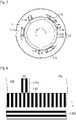
Figur 4 ist ein Ausschnitt einer mantelseitigen Ansicht auf das Skalenelement 1.21 gezeigt. Das Skalenelement 1.21 ist im vorgestellten Ausführungsbeispiel als ein zylindrischer beziehungsweise ringförmiger Körper ausgebildet, an dessen Mantelseite gemäß derFigur 4 eine Skala 1.22 aufgebracht ist. Diese umfasst eine erste Teilung 1.221 als auch eine zweite Teilung 1.222, wobei die zweite Teilung 1.222 gegenüber der ersten Teilung 1.221 bezüglich der ersten Richtungsachse x versetzt angeordnet ist. - Die erste Teilung 1.221 umfasst regelmäßige Strukturen beziehungsweise Linien, die parallel entlang der Umfangsrichtung u versetzt zueinander aneinandergereiht angeordnet sind. Zudem umfasst die erste Teilung 1.221 eine Referenzmarke 1.223.
- Die zweite Teilung 1.222 umfasst regelmäßige Strukturen beziehungsweise Linien, die entlang der ersten Richtungsachse x parallel zueinander aneinandergereiht angeordnet sind.
- Die Strukturen der ersten Teilung 1.221, der zweiten Teilung 1.222 und die der Referenzmarke 1.223 sind im vorgestellten Ausführungsbeispiel als für Licht reflektierende und nicht reflektierende Streifen ausgestaltet.
- Gemäß der
Figur 3 weist die Messeinrichtung 1 drei erste Positionsaufnehmer 1.11, 1.13, 1.15 und drei zweite Positionsaufnehmer 1.12, 1.14, 1.16 auf. Die Positionsaufnehmer 1.11, 1.12, 1.13, 1.14, 1.15, 1.16 sind in Umfangsrichtung u jeweils versetzt zueinander angeordnet und dem Skalenelement 1.21 mit einem radialen Luftspalt gegenüber liegend, insbesondere entlang einer Kreislinie, angeordnet. Zudem weist hier jeder Positionsaufnehmer 1.11, 1.12, 1.13, 1.14, 1.15, 1.16 im vorgestellten Ausführungsbeispiel ein Gehäuse auf, in dem entsprechende fotosensitive Sensorelemente angeordnet sind. Alternativ dazu kann auch auf die Gehäuse verzichtet werden oder es können auch mehrere Sensorelemente in ein und demselben Gehäuse angeordnet sein. Beispielsweise können mehrere oder alle Positionsaufnehmer 1.11, 1.12, 1.13, 1.14, 1.15, 1.16 auch auf ein und derselben Platine montiert sein. - Zudem ist gemäß der
Figur 2 am drehbaren Bauelement R ein Stellglied 3 montiert. Dieses befindet sich bezüglich der Messeinrichtung 1 am anderen Ende des drehbaren Bauelements R, so dass also die Wicklung des Antriebes zwischen der Messeinrichtung 1 und dem Stellglied 3 angeordnet ist. Das Stellglied 3 umfasst im vorgestellten Ausführungsbeispiel gemäß derFigur 5 drei Aktuatoren 3.1, 3.2, 3.3, die um jeweils 120° versetzt sternförmig angeordnet sind. Die radial außen liegenden Enden der Aktuatoren 3.1, 3.2, 3.3 sind an der ortsfesten Struktur S befestigt und radial innen mit einem Lager 3.4 verbunden. Im vorgestellten Ausführungsbeispiel ist das Lager 3.4 als ein Wälzlager ausgestaltet, dessen Innenring an dem drehbaren Bauelement R befestigt ist. Die Aktuatoren 3.1, 3.2, 3.3 sind längenveränderlich. Im vorgestellten Ausführungsbeispiel wird die Längenänderung durch ein Piezo-Prinzip erreicht. Dabei greifen die Aktuatoren 3.1, 3.2, 3.3 beziehungsweise die von den Aktuatoren 3.1, 3.2, 3.3 erzeugten Stellkräfte am Lager 3.4 an, insbesondere am Außenring des Lagers 3.4. Folglich ist das Stellglied 3 am drehbaren Bauelement R so montiert, dass durch Betätigen des Stellglieds 3 die Orientierung der Drehachse A relativ zur ersten Bauteilgruppe 1.1 veränderbar ist. - Das Skalenelement 1.21 vermag durch seine erste Teilung 1.221 das eingestrahlte Licht entsprechend der Winkelstellung des Skalenelements 1.21 zu modulieren. Durch die zweite Teilung 1.222 wird das eingestrahlte Licht entsprechend der axialen Position des Skalenelements 1.21 beziehungsweise des drehbaren Bauelements R moduliert. Das modulierte Licht trifft auf die Sensorelemente der Positionsaufnehmer 1.11, 1.12, 1.13, 1.14, 1.15, 1.16.
- Durch die ersten Positionsaufnehmer 1.11, 1.13, 1.15 ist die erste Teilung 1.221 in der Weise abtastbar, dass durch die ersten Positionsaufnehmer 1.11, 1.13, 1.15 eine Winkelstellung des Skalenelements 1.21 in Bezug auf die ersten Positionsaufnehmer 1.11, 1.13, 1.15 bestimmbar ist. Dabei kann die Winkelstellung innerhalb einer Umdrehung hinweg absolut bestimmt werden. Zu diesem Zweck kann wie in der
Figur 4 gezeigt eine an sich inkrementale erste Teilung 1.221 verwendet werden, durch die in Verbindung mit der Referenzmarke 1.223 eine absolute Winkelstellung über eine Umdrehung hinweg erzeugbar ist. Alternativ kann die erste Teilung 1.221 absolut, zum Beispiel als Pseudo-Random-Code oder Gray-Code, im Sinne einer Codierung, also mit einer Erzeugung eines eindeutigen Codewerts ausgestaltet sein. Die Signale der ersten Positionsaufnehmer 1.11, 1.13, 1.15 werden zu einer elektronischen Schaltung geleitet, wo insbesondere digitale Werte der Winkelstellung erzeugt werden. Außerdem kann durch geeignete Verknüpfung der Positionssignale der ersten Positionsaufnehmer 1.11, 1.13, 1.15 die Position des Skalenelements 1.21 in einer Ebene P, die senkrecht zur Drehachse A orientiert ist, bestimmt werden, also die y-z-Koordinaten der tatsächlichen Lage der Drehachse A. Diese Position, die auch als laterale Position bezeichnet werden kann, hängt bei dem gegebenen Werkstückhalter W von der Belastung während der Bearbeitung ab. Zudem wird der aktuellen lateralen Position auch die absolute Winkelstellung des drehbaren Bauelements R zugeordnet. - Ebenso sind die zweiten Positionsaufnehmer 1.12, 1.14, 1.16 mit der elektronischen Schaltung elektrisch verbunden. Die zweiten Positionsaufnehmer 1.12, 1.14, 1.16 dienen zur Abtastung der zweiten Teilung 1.222, wobei durch die zweiten Positionsaufnehmer 1.12, 1.14, 1.16 die axiale Position oder die Orientierung des Skalenelements 1.21 bestimmbar ist. In der elektronischen Schaltung wird auch der axialen Position die absolute Winkelstellung des drehbaren Bauelements R zugeordnet.
- Demgemäß kann durch die Messeinrichtung 1 eine Messung der relativen Position zwischen der ersten Bauteilgruppe 1.1 und der zweiten Bauteilgruppe 1.2 in mehreren Dimensionen durchgeführt werden, insbesondere werden Exzentrizitäten, Taumelbewegungen oder axiale Verschiebungen des drehbaren Bauelements R relativ zur ortsfesten Struktur S bestimmt. Durch die Vorrichtung ist es möglich insbesondere bei Rundtischen in Abhängigkeit von der absoluten Winkelstellung des drehbaren Bauelements R deren laterale und axiale Position zu messen. Dadurch, dass Rundtische ohnehin sehr steif konstruiert sind, werden hier Positionsmessungen durchgeführt, die sich im µm-Bereich oder weniger bewegen. Ebenso wird die (Ist-) Orientierung der Drehachse A relativ zur ortsfesten Struktur S gemessen. Auch zu diesem Zweck ist eine hohe Auflösung insbesondere der zweiten Positionsaufnehmer 1.12, 1.14, 1.16 erforderlich.
- In der
Figur 6 ist eine vereinfachte prinzipielle Anordnung einer Vorrichtung zur Korrektur von Positionsabweichungen zwischen einem Werkzeughalter T und einem Werkstückhalter W einer Bearbeitungsmaschine gezeigt, welche wie durch die strich-punktierte Eingrenzung in derFigur 6 dargestellt, die Messeinrichtung 1, eine Regeleinrichtung 2, das Stellglied 3 sowie eine Steuerung 4 umfasst. - Durch die Messeinrichtung 1 sind wie oben beschrieben während des Betriebes der Bearbeitungsmaschine erste Signale S1 erzeugbar, welche eine Information der aktuellen tatsächlichen Orientierung der Drehachse A relativ zur ersten Richtungsachse x beinhalten, das heißt eine Information über die Verkippung der Drehachse A. Zur Übertragung der ersten Signale S1 ist die Messeinrichtung 1 mit der Regeleinrichtung 2 zum Beispiel über ein Kabel verbunden. Die eingehende Information über die Orientierung der Drehachse A, also die tatsächliche Lage der Drehachse A im Raum, wird durch die ersten Signale S1 der Regeleinrichtung 2 zugeführt. Gemäß bekannten Verfahrensschritten zur Regelung wird die Abweichung der Orientierung der Drehachse A von der Orientierung der ersten Richtungsachse x in Betrag und Richtung bestimmt. Dann wird die Drehachse A durch Betätigen des Stellglieds 3, hier die drei Aktuatoren 3.1, 3.2, 3.3, in eine Richtung gedrängt, so dass die Drehachse A innerhalb vordefinierter Toleranzen parallel zur ersten Richtungsachse x ausgerichtet wird, also in die Sollorientierung gebracht wird. Als Störgrößen, die dafür verantwortlich sind, dass die Orientierung der Drehachse A gegenüber der ersten Richtungsachse x verkippt, kommen beispielsweise Gewichtskräfte des Werkstückes, Abdrängkräfte des Werkzeuges bei der Bearbeitung oder Ratter-Schwingungen in Betracht. Wenn nun die Regeleinrichtung arbeitet ist das Werkzeug relativ zum Werkstück in einem korrekten Winkel orientiert.
- Zur weiteren Steigerung der Präzision der Bearbeitungsmaschine werden durch die Messeinrichtung zweite Signale S2 erzeugt, die eine Information der tatsächlichen translatorischen Position der ersten Bauteilgruppe 1.1 relativ zur zweiten Bauteilgruppe 1.2 in der ersten Richtungsachse x, in der zweiten Richtungsachse y und in der dritten Richtungsachse z beinhalten. Die zweiten Signale S2 beinhalten also die Lage der Drehachse A beziehungsweise deren translatorische Verschiebung in der Ebene P beziehungsweise in einer y-z-Ebene. Die Messeinrichtung 1 ist mit der Steuerung 4 der Bearbeitungsmaschine zur Übertragung der zweiten Signale S2 verbunden. Die Steuerung 4 dient unter anderem dazu programmierte Steuerbefehle zu verarbeiten und in Bewegungsabläufe umzusetzen. Hierzu werden von der Steuerung 4 Steuersignale Sx, Sy, Sz an Antriebe Dx, Dy, Dz übertragen, die bewirken, dass der Werkzeughalter T lateral relativ zur ortsfesten Struktur S bewegt wird, gemäß den Doppelpfeilen in der
Figur 1 in der ersten Richtungsachse x, der zweiten Richtungsachse y und der dritten Richtungsachse z. Die Ist-Positionen werden durch Positionsmessgeräte Lx, Ly, Lz erfasst und entsprechende Ist-Positionswerte beziehungsweise Positionssignale Px, Py, Pz der Steuerung 4 zur Lageregelung, wie bei CNC-Maschinen üblich, zugeführt. Zudem wird auch die Bewegung des drehbaren Bauelements R und damit des Werkstückhalters W durch die Steuerung 4 gesteuert. In diesem Zusammenhang empfängt die Steuerung 4 von der Messeinrichtung 1 die Ist-Winkelstellung beziehungsweise Winkelstellungssignale Pr des drehbaren Bauelements R relativ zur ortsfesten Struktur S und gibt entsprechende Steuersignale Sr an den Antrieb des Werkstückhalters W weiter. - Wie oben beschrieben, werden durch die Messeinrichtung 1 nicht nur die Orientierung der Drehachse A, sondern auch die lateralen Verschiebungen des Werkstückträgers W gemessen. Diese Verschiebungen in den Richtungen der ersten Richtungsachse x, der zweiten Richtungsachse y und der dritten Richtungsachse z werden zur Korrektur der relativen Position zwischen dem Werkzeughalter T und dem Werkstückhalter W in der Steuerung 4 berücksichtigt und mit Hilfe der Antriebe ausgeglichen. Somit beinhalten die von der Steuerung 4 an die Antriebe Dx, Dy, Dz übertragenen Signale Sx, Sy, Sz bereits korrigierte Positionswerte.
- Auf diese Weise kann also einerseits eine korrekte Orientierung der Drehachse A durch die Regeleinrichtung 2 und eine exakte Positionierung des Werkzeughalters T relativ zum Werkstückhalter W durch die Steuerung erreicht werden.
- Die Regeleinrichtung 2 ist also so konfiguriert, dass in Abhängigkeit von der Abweichung der tatsächlichen Orientierung der Drehachse A von der Orientierung der ersten Richtungsachse x das Stellglied 3 in der Weise ansteuerbar ist, dass diese Abweichung reduziert wird. Zudem wird in Abhängigkeit von der Abweichung der tatsächlichen Position der Drehachse A von einer SollPosition in der ersten Ebene P die Position der Drehachse A durch das Stellelement korrigiert.
Claims (9)
- Vorrichtung umfassend eine Messeinrichtung (1), eine Regeleinrichtung (2), ein Stellglied (3) sowie eine Steuerung (4), wobei die Vorrichtung dazu geeignet ist Positionsabweichungen zwischen einem Werkzeughalter (T) und einem Werkstückhalter (W) einer Bearbeitungsmaschine zu korrigieren, wobeidie Messeinrichtung (1) eine erste Bauteilgruppe (1.1) und einezweite Bauteilgruppe (1.2) umfasst, und die erste Bauteilgruppe (1.1) und die zweite Bauteilgruppe (1.2) relativ zueinander um eine Drehachse (A) drehbar sind, wobei¬ die erste Bauteilgruppe (1.1) ortsfest angeordnet ist bezüglich eines kartesischen Koordinatensystems mit einer ersten Richtungsachse (x), einer zweiten Richtungsachse (y) und einer dritten Richtungsachse (z),¬ die zweite Bauteilgruppe (1.2) an einem um die Drehachse (A) drehbaren Bauelement (R) befestigbar ist, so dass die Drehachse (A) im kartesischen Koordinatensystem parallel zur ersten Richtungsachse (x) verläuft unddurch die Messeinrichtung (1) eine Messung der relativen Position zwischen der ersten Bauteilgruppe (1.1) und der zweiten Bauteilgruppe (1.2) in mehreren Dimensionen durchführbar ist, wobei durch die Messeinrichtung (1)- erste Signale (S1) erzeugbar sind, welche eine Information der tatsächlichen Orientierung der Drehachse (A) relativ zur ersten Richtungsachse (x) beinhalten, sowie- zweite Signale (S2) erzeugbar sind, die eine Information der tatsächlichen Position der ersten Bauteilgruppe (1.1) relativ zur zweiten Bauteilgruppe (1.2) in der ersten Richtungsachse (x) und / oder der zweiten Richtungsachse (y) und / oder der dritten Richtungsachse (z) beinhalten, wobeidie Messeinrichtung (1) mit der Regeleinrichtung (2) zur Übertragung der ersten Signale (S1) verbunden ist, unddas Stellglied (3) am Bauelement (R) so montierbar ist, dass durch Betätigen des Stellglieds (3) die Orientierung der Drehachse (A) relativ zur ersten Bauteilgruppe (1.1) veränderbar ist unddie Regeleinrichtung (2) so konfiguriert ist, dass in Abhängigkeit von der Information der tatsächlichen Orientierung der Drehachse (A) relativ zur ersten Richtungsachse (x) die Drehachse (A) mit Hilfe des Stellglieds (3) in eine Sollorientierung bringbar ist und weiterhindie Messeinrichtung (1) mit der Steuerung (4) zur Übertragung der zweiten Signale (S2) verbunden ist zur Korrektur der relativen Position zwischen dem Werkzeughalter (T) und dem Werkstückhalter (W).
- Vorrichtung gemäß dem Anspruch 1, wobei das Stellglied (3) zumindest zwei Aktuatoren (3.1, 3.2, 3.3) umfasst.
- Vorrichtung gemäß dem Anspruch 1, wobei das Stellglied (3) drei Aktuatoren (3.1, 3.2, 3.3) umfasst, welche sternförmig angeordnet sind.
- Vorrichtung gemäß dem Anspruch 1, wobei das Stellglied (3) genau einen Aktuator (3.1, 3.2, 3.3) aufweist.
- Vorrichtung gemäß einem der vorhergehenden Ansprüche, wobei das Stellglied (3) zumindest einen Aktuator (3.1, 3.2, 3.3) und ein Lager (3.4) umfasst, wobei der zumindest eine Aktuator (3.1, 3.2, 3.3) an dem Lager (3.4) angreift.
- Vorrichtung gemäß einem der vorhergehenden Ansprüche, wobei das Stellglied (3) zumindest einen Aktuator (3.1, 3.2, 3.3) und ein Lager (3.4) umfasst, wobei das Lager (3.4) an dem drehbaren Bauelement (R) montierbar ist.
- Vorrichtung gemäß einem der vorhergehenden Ansprüche, wobei das Stellglied (3) zumindest einen Aktuator (3.1, 3.2, 3.3) umfasst, dessen Funktion auf einem Piezo-Effekt beruht.
- Vorrichtung gemäß einem der vorhergehenden Ansprüche, wobei das Stellglied (3) zumindest einen Aktuator (3.1, 3.2, 3.3) umfasst, der ein Keilgetriebe aufweist.
- Vorrichtung gemäß einem der vorhergehenden Ansprüche, wobei durch die Messeinrichtung (1) eine Messung der Winkelstellung zwischen der ersten Bauteilgruppe (1.1) und der zweiten Bauteilgruppe (1.2) durchführbar ist und Winkelstellungssignale (Pr) erzeugbar sind, welche eine Information der Winkelstellung beinhalten, wobei die Messeinrichtung (1) mit der Steuerung (4) zur Übertragung der Winkelstellungssignale (Pr) verbunden ist.
Applications Claiming Priority (1)
| Application Number | Priority Date | Filing Date | Title |
|---|---|---|---|
| DE102021207479.0A DE102021207479A1 (de) | 2021-07-14 | 2021-07-14 | Vorrichtung zur korrektur von positionsabweichungen einer bearbeitungsmaschine |
Publications (2)
| Publication Number | Publication Date |
|---|---|
| EP4119288A1 true EP4119288A1 (de) | 2023-01-18 |
| EP4119288B1 EP4119288B1 (de) | 2023-10-04 |
Family
ID=81846519
Family Applications (1)
| Application Number | Title | Priority Date | Filing Date |
|---|---|---|---|
| EP22168306.3A Active EP4119288B1 (de) | 2021-07-14 | 2022-04-14 | Vorrichtung zur korrektur von positionsabweichungen einer bearbeitungsmaschine |
Country Status (3)
| Country | Link |
|---|---|
| EP (1) | EP4119288B1 (de) |
| DE (1) | DE102021207479A1 (de) |
| ES (1) | ES2969306T3 (de) |
Citations (5)
| Publication number | Priority date | Publication date | Assignee | Title |
|---|---|---|---|---|
| EP1175960A2 (de) * | 2000-07-24 | 2002-01-30 | Fritz Studer AG | Verfahren und Vorrichtung zum Austrichten einer Werkstückachse in Bezug auf eine Werkzeugachse an einer Werkzeugmaschine |
| JP2008073791A (ja) * | 2006-09-20 | 2008-04-03 | Olympus Corp | 工具段取り装置、工具段取り方法 |
| WO2015022398A1 (de) * | 2013-08-14 | 2015-02-19 | Carl Zeiss Industrielle Messtechnik Gmbh | Reduzieren von fehlern einer drehvorrichtung, insbesondere für die bestimmung von koordinaten eines werkstücks oder die bearbeitung eines werkstücks |
| EP3591344A1 (de) | 2018-07-04 | 2020-01-08 | Dr. Johannes Heidenhain GmbH | Messeinrichtung für eine spindel oder einen rundtisch |
| EP3760980A1 (de) | 2019-07-04 | 2021-01-06 | Dr. Johannes Heidenhain GmbH | Winkelmesseinrichtung |
-
2021
- 2021-07-14 DE DE102021207479.0A patent/DE102021207479A1/de not_active Withdrawn
-
2022
- 2022-04-14 EP EP22168306.3A patent/EP4119288B1/de active Active
- 2022-04-14 ES ES22168306T patent/ES2969306T3/es active Active
Patent Citations (5)
| Publication number | Priority date | Publication date | Assignee | Title |
|---|---|---|---|---|
| EP1175960A2 (de) * | 2000-07-24 | 2002-01-30 | Fritz Studer AG | Verfahren und Vorrichtung zum Austrichten einer Werkstückachse in Bezug auf eine Werkzeugachse an einer Werkzeugmaschine |
| JP2008073791A (ja) * | 2006-09-20 | 2008-04-03 | Olympus Corp | 工具段取り装置、工具段取り方法 |
| WO2015022398A1 (de) * | 2013-08-14 | 2015-02-19 | Carl Zeiss Industrielle Messtechnik Gmbh | Reduzieren von fehlern einer drehvorrichtung, insbesondere für die bestimmung von koordinaten eines werkstücks oder die bearbeitung eines werkstücks |
| EP3591344A1 (de) | 2018-07-04 | 2020-01-08 | Dr. Johannes Heidenhain GmbH | Messeinrichtung für eine spindel oder einen rundtisch |
| EP3760980A1 (de) | 2019-07-04 | 2021-01-06 | Dr. Johannes Heidenhain GmbH | Winkelmesseinrichtung |
Also Published As
| Publication number | Publication date |
|---|---|
| EP4119288B1 (de) | 2023-10-04 |
| DE102021207479A1 (de) | 2023-01-19 |
| ES2969306T3 (es) | 2024-05-17 |
Similar Documents
| Publication | Publication Date | Title |
|---|---|---|
| EP3591344B1 (de) | Messeinrichtung für eine spindel oder einen rundtisch | |
| DE69432192T2 (de) | Linearantrieb | |
| DE69230137T2 (de) | Vorschubvorrichtung mit einer schraube und mit einer feineinstellung | |
| DE3878557T2 (de) | Haltevorrichtung fuer einen eine oberflaeche abtastenden taststift. | |
| EP1577043B1 (de) | Vorrichtung, CNC-Messgerät und Verfahren zum Vermessen eines rotationssymmetrischen Präzisionsteiles | |
| DE3423873A1 (de) | Rheometer | |
| EP2093537A1 (de) | Verfahren und Vorrichtung zur Ermittlung einer Ausrichtung von zwei drehbar gelagerten Maschinenteilen, einer Ausrichtung von zwei hohlzylinderförmigen Maschinenteilen oder zur Prüfung einer Komponente auf Geradheit entlang einer Längsseite | |
| EP0679510A1 (de) | Verfahren und Vorrichtung zur Herstellung einer Siebdruckschablone | |
| DE102009044602A9 (de) | Kompakter Linearaktor und Verfahren zur Herstellung desselben | |
| EP3964903B1 (de) | Vorrichtung und verfahren zur verarbeitung von rotationsabhängigen messwerten | |
| DE102015226387A1 (de) | Verfahren zur Durchführung von Messungen mit einem Prüfelement in einem Koordinatenmessgerät oder einer Werkzeugmaschine | |
| WO2010130420A1 (de) | Einrichtung und verfahren zur positions- und lageermittlung | |
| EP1322918B1 (de) | Vorrichtung und verfahren zur erfassung der rotationsbewegung eines um eine achse drehbar gelagerten elementes | |
| EP3760980B1 (de) | Winkelmesseinrichtung | |
| DE10345993B4 (de) | Verfahren und Vorrichtung zum Messen und zum Feinstellen eines Werkzeuges in einem Werkzeughalter und Verfahren zum Messen einer Bearbeitungskraft | |
| EP1638720B1 (de) | Werkzeugmaschine mit zueinander verstellbaren parallelen werkzeugspindeln | |
| EP3760981B1 (de) | Winkelmesseinrichtung und verfahren zum betrieb einer winkelmesseinrichtung | |
| EP4119288B1 (de) | Vorrichtung zur korrektur von positionsabweichungen einer bearbeitungsmaschine | |
| DE10135960B4 (de) | Absolutpositions-Detektionsvorrichtung für einen Linearbetätiger | |
| DE10116672A1 (de) | Verfahren und Vorrichtung zur Materialbearbeitung | |
| DE9422389U1 (de) | Werkzeugschneiden-Verstelleinrichtung zum hochgenauen Bearbeiten von runden, unrunden und/oder nicht zylinderförmigen Innen- und/oder Außenkonturen | |
| DE102014217517A1 (de) | Vorrichtung zur Steuerung einer relativen Verlagerung einer ersten Halterung und einer zweiten Halterung | |
| EP1943042B1 (de) | Verfahren und vorrichtung zur finishbearbeitung von bohrungen | |
| DE10116869A1 (de) | Verfahren und Vorrichtung zum Auswuchten von rotierenden Körpern | |
| LU505407B1 (de) | Drehgeber, verfahren und anordnung jeweils zur positionsbestimmung und deren verwendung |
Legal Events
| Date | Code | Title | Description |
|---|---|---|---|
| PUAI | Public reference made under article 153(3) epc to a published international application that has entered the european phase |
Free format text: ORIGINAL CODE: 0009012 |
|
| STAA | Information on the status of an ep patent application or granted ep patent |
Free format text: STATUS: REQUEST FOR EXAMINATION WAS MADE |
|
| 17P | Request for examination filed |
Effective date: 20220414 |
|
| AK | Designated contracting states |
Kind code of ref document: A1 Designated state(s): AL AT BE BG CH CY CZ DE DK EE ES FI FR GB GR HR HU IE IS IT LI LT LU LV MC MK MT NL NO PL PT RO RS SE SI SK SM TR |
|
| GRAP | Despatch of communication of intention to grant a patent |
Free format text: ORIGINAL CODE: EPIDOSNIGR1 |
|
| STAA | Information on the status of an ep patent application or granted ep patent |
Free format text: STATUS: GRANT OF PATENT IS INTENDED |
|
| RIC1 | Information provided on ipc code assigned before grant |
Ipc: B23Q 17/00 20060101ALI20230602BHEP Ipc: B23Q 17/22 20060101ALI20230602BHEP Ipc: B23Q 1/52 20060101ALI20230602BHEP Ipc: G05B 19/19 20060101ALI20230602BHEP Ipc: G01D 5/00 20060101ALI20230602BHEP Ipc: B23Q 1/25 20060101AFI20230602BHEP |
|
| INTG | Intention to grant announced |
Effective date: 20230622 |
|
| RBV | Designated contracting states (corrected) |
Designated state(s): AL AT BE BG CH CY CZ DE DK EE ES FI FR GB GR HR HU IE IS IT LI LT LU LV MC MK MT NL NO PL PT RO RS SE SI SK SM TR |
|
| GRAS | Grant fee paid |
Free format text: ORIGINAL CODE: EPIDOSNIGR3 |
|
| GRAA | (expected) grant |
Free format text: ORIGINAL CODE: 0009210 |
|
| STAA | Information on the status of an ep patent application or granted ep patent |
Free format text: STATUS: THE PATENT HAS BEEN GRANTED |
|
| AK | Designated contracting states |
Kind code of ref document: B1 Designated state(s): AL AT BE BG CH CY CZ DE DK EE ES FI FR GB GR HR HU IE IS IT LI LT LU LV MC MK MT NL NO PL PT RO RS SE SI SK SM TR |
|
| REG | Reference to a national code |
Ref country code: GB Ref legal event code: FG4D Free format text: NOT ENGLISH |
|
| REG | Reference to a national code |
Ref country code: CH Ref legal event code: EP |
|
| REG | Reference to a national code |
Ref country code: IE Ref legal event code: FG4D Free format text: LANGUAGE OF EP DOCUMENT: GERMAN |
|
| REG | Reference to a national code |
Ref country code: DE Ref legal event code: R096 Ref document number: 502022000175 Country of ref document: DE |
|
| REG | Reference to a national code |
Ref country code: LT Ref legal event code: MG9D |
|
| REG | Reference to a national code |
Ref country code: NL Ref legal event code: MP Effective date: 20231004 |
|
| PG25 | Lapsed in a contracting state [announced via postgrant information from national office to epo] |
Ref country code: NL Free format text: LAPSE BECAUSE OF FAILURE TO SUBMIT A TRANSLATION OF THE DESCRIPTION OR TO PAY THE FEE WITHIN THE PRESCRIBED TIME-LIMIT Effective date: 20231004 |
|
| PG25 | Lapsed in a contracting state [announced via postgrant information from national office to epo] |
Ref country code: GR Free format text: LAPSE BECAUSE OF FAILURE TO SUBMIT A TRANSLATION OF THE DESCRIPTION OR TO PAY THE FEE WITHIN THE PRESCRIBED TIME-LIMIT Effective date: 20240105 |
|
| PG25 | Lapsed in a contracting state [announced via postgrant information from national office to epo] |
Ref country code: IS Free format text: LAPSE BECAUSE OF FAILURE TO SUBMIT A TRANSLATION OF THE DESCRIPTION OR TO PAY THE FEE WITHIN THE PRESCRIBED TIME-LIMIT Effective date: 20240204 |
|
| PG25 | Lapsed in a contracting state [announced via postgrant information from national office to epo] |
Ref country code: LT Free format text: LAPSE BECAUSE OF FAILURE TO SUBMIT A TRANSLATION OF THE DESCRIPTION OR TO PAY THE FEE WITHIN THE PRESCRIBED TIME-LIMIT Effective date: 20231004 |
|
| PG25 | Lapsed in a contracting state [announced via postgrant information from national office to epo] |
Ref country code: LT Free format text: LAPSE BECAUSE OF FAILURE TO SUBMIT A TRANSLATION OF THE DESCRIPTION OR TO PAY THE FEE WITHIN THE PRESCRIBED TIME-LIMIT Effective date: 20231004 Ref country code: IS Free format text: LAPSE BECAUSE OF FAILURE TO SUBMIT A TRANSLATION OF THE DESCRIPTION OR TO PAY THE FEE WITHIN THE PRESCRIBED TIME-LIMIT Effective date: 20240204 Ref country code: GR Free format text: LAPSE BECAUSE OF FAILURE TO SUBMIT A TRANSLATION OF THE DESCRIPTION OR TO PAY THE FEE WITHIN THE PRESCRIBED TIME-LIMIT Effective date: 20240105 Ref country code: BG Free format text: LAPSE BECAUSE OF FAILURE TO SUBMIT A TRANSLATION OF THE DESCRIPTION OR TO PAY THE FEE WITHIN THE PRESCRIBED TIME-LIMIT Effective date: 20240104 Ref country code: PT Free format text: LAPSE BECAUSE OF FAILURE TO SUBMIT A TRANSLATION OF THE DESCRIPTION OR TO PAY THE FEE WITHIN THE PRESCRIBED TIME-LIMIT Effective date: 20240205 |
|
| REG | Reference to a national code |
Ref country code: ES Ref legal event code: FG2A Ref document number: 2969306 Country of ref document: ES Kind code of ref document: T3 Effective date: 20240517 |
|
| PG25 | Lapsed in a contracting state [announced via postgrant information from national office to epo] |
Ref country code: SE Free format text: LAPSE BECAUSE OF FAILURE TO SUBMIT A TRANSLATION OF THE DESCRIPTION OR TO PAY THE FEE WITHIN THE PRESCRIBED TIME-LIMIT Effective date: 20231004 Ref country code: RS Free format text: LAPSE BECAUSE OF FAILURE TO SUBMIT A TRANSLATION OF THE DESCRIPTION OR TO PAY THE FEE WITHIN THE PRESCRIBED TIME-LIMIT Effective date: 20231004 Ref country code: PL Free format text: LAPSE BECAUSE OF FAILURE TO SUBMIT A TRANSLATION OF THE DESCRIPTION OR TO PAY THE FEE WITHIN THE PRESCRIBED TIME-LIMIT Effective date: 20231004 Ref country code: NO Free format text: LAPSE BECAUSE OF FAILURE TO SUBMIT A TRANSLATION OF THE DESCRIPTION OR TO PAY THE FEE WITHIN THE PRESCRIBED TIME-LIMIT Effective date: 20240104 Ref country code: LV Free format text: LAPSE BECAUSE OF FAILURE TO SUBMIT A TRANSLATION OF THE DESCRIPTION OR TO PAY THE FEE WITHIN THE PRESCRIBED TIME-LIMIT Effective date: 20231004 Ref country code: HR Free format text: LAPSE BECAUSE OF FAILURE TO SUBMIT A TRANSLATION OF THE DESCRIPTION OR TO PAY THE FEE WITHIN THE PRESCRIBED TIME-LIMIT Effective date: 20231004 |
|
| REG | Reference to a national code |
Ref country code: DE Ref legal event code: R097 Ref document number: 502022000175 Country of ref document: DE |
|
| PG25 | Lapsed in a contracting state [announced via postgrant information from national office to epo] |
Ref country code: DK Free format text: LAPSE BECAUSE OF FAILURE TO SUBMIT A TRANSLATION OF THE DESCRIPTION OR TO PAY THE FEE WITHIN THE PRESCRIBED TIME-LIMIT Effective date: 20231004 |
|
| PG25 | Lapsed in a contracting state [announced via postgrant information from national office to epo] |
Ref country code: CZ Free format text: LAPSE BECAUSE OF FAILURE TO SUBMIT A TRANSLATION OF THE DESCRIPTION OR TO PAY THE FEE WITHIN THE PRESCRIBED TIME-LIMIT Effective date: 20231004 |
|
| PG25 | Lapsed in a contracting state [announced via postgrant information from national office to epo] |
Ref country code: SK Free format text: LAPSE BECAUSE OF FAILURE TO SUBMIT A TRANSLATION OF THE DESCRIPTION OR TO PAY THE FEE WITHIN THE PRESCRIBED TIME-LIMIT Effective date: 20231004 |
|
| PG25 | Lapsed in a contracting state [announced via postgrant information from national office to epo] |
Ref country code: SM Free format text: LAPSE BECAUSE OF FAILURE TO SUBMIT A TRANSLATION OF THE DESCRIPTION OR TO PAY THE FEE WITHIN THE PRESCRIBED TIME-LIMIT Effective date: 20231004 Ref country code: SK Free format text: LAPSE BECAUSE OF FAILURE TO SUBMIT A TRANSLATION OF THE DESCRIPTION OR TO PAY THE FEE WITHIN THE PRESCRIBED TIME-LIMIT Effective date: 20231004 Ref country code: RO Free format text: LAPSE BECAUSE OF FAILURE TO SUBMIT A TRANSLATION OF THE DESCRIPTION OR TO PAY THE FEE WITHIN THE PRESCRIBED TIME-LIMIT Effective date: 20231004 Ref country code: EE Free format text: LAPSE BECAUSE OF FAILURE TO SUBMIT A TRANSLATION OF THE DESCRIPTION OR TO PAY THE FEE WITHIN THE PRESCRIBED TIME-LIMIT Effective date: 20231004 Ref country code: DK Free format text: LAPSE BECAUSE OF FAILURE TO SUBMIT A TRANSLATION OF THE DESCRIPTION OR TO PAY THE FEE WITHIN THE PRESCRIBED TIME-LIMIT Effective date: 20231004 Ref country code: CZ Free format text: LAPSE BECAUSE OF FAILURE TO SUBMIT A TRANSLATION OF THE DESCRIPTION OR TO PAY THE FEE WITHIN THE PRESCRIBED TIME-LIMIT Effective date: 20231004 |
|
| PLBE | No opposition filed within time limit |
Free format text: ORIGINAL CODE: 0009261 |
|
| STAA | Information on the status of an ep patent application or granted ep patent |
Free format text: STATUS: NO OPPOSITION FILED WITHIN TIME LIMIT |
|
| 26N | No opposition filed |
Effective date: 20240705 |
|
| PG25 | Lapsed in a contracting state [announced via postgrant information from national office to epo] |
Ref country code: SI Free format text: LAPSE BECAUSE OF FAILURE TO SUBMIT A TRANSLATION OF THE DESCRIPTION OR TO PAY THE FEE WITHIN THE PRESCRIBED TIME-LIMIT Effective date: 20231004 |
|
| PG25 | Lapsed in a contracting state [announced via postgrant information from national office to epo] |
Ref country code: SI Free format text: LAPSE BECAUSE OF FAILURE TO SUBMIT A TRANSLATION OF THE DESCRIPTION OR TO PAY THE FEE WITHIN THE PRESCRIBED TIME-LIMIT Effective date: 20231004 |
|
| PG25 | Lapsed in a contracting state [announced via postgrant information from national office to epo] |
Ref country code: MC Free format text: LAPSE BECAUSE OF FAILURE TO SUBMIT A TRANSLATION OF THE DESCRIPTION OR TO PAY THE FEE WITHIN THE PRESCRIBED TIME-LIMIT Effective date: 20231004 |
|
| PG25 | Lapsed in a contracting state [announced via postgrant information from national office to epo] |
Ref country code: MC Free format text: LAPSE BECAUSE OF FAILURE TO SUBMIT A TRANSLATION OF THE DESCRIPTION OR TO PAY THE FEE WITHIN THE PRESCRIBED TIME-LIMIT Effective date: 20231004 |
|
| PG25 | Lapsed in a contracting state [announced via postgrant information from national office to epo] |
Ref country code: LU Free format text: LAPSE BECAUSE OF NON-PAYMENT OF DUE FEES Effective date: 20240414 |
|
| REG | Reference to a national code |
Ref country code: BE Ref legal event code: MM Effective date: 20240430 |
|
| PG25 | Lapsed in a contracting state [announced via postgrant information from national office to epo] |
Ref country code: LU Free format text: LAPSE BECAUSE OF NON-PAYMENT OF DUE FEES Effective date: 20240414 |
|
| PG25 | Lapsed in a contracting state [announced via postgrant information from national office to epo] |
Ref country code: BE Free format text: LAPSE BECAUSE OF NON-PAYMENT OF DUE FEES Effective date: 20240430 |
|
| PG25 | Lapsed in a contracting state [announced via postgrant information from national office to epo] |
Ref country code: FR Free format text: LAPSE BECAUSE OF NON-PAYMENT OF DUE FEES Effective date: 20240430 |
|
| PG25 | Lapsed in a contracting state [announced via postgrant information from national office to epo] |
Ref country code: FR Free format text: LAPSE BECAUSE OF NON-PAYMENT OF DUE FEES Effective date: 20240430 Ref country code: BE Free format text: LAPSE BECAUSE OF NON-PAYMENT OF DUE FEES Effective date: 20240430 |
|
| PG25 | Lapsed in a contracting state [announced via postgrant information from national office to epo] |
Ref country code: IE Free format text: LAPSE BECAUSE OF NON-PAYMENT OF DUE FEES Effective date: 20240414 |
|
| PG25 | Lapsed in a contracting state [announced via postgrant information from national office to epo] |
Ref country code: CY Free format text: LAPSE BECAUSE OF FAILURE TO SUBMIT A TRANSLATION OF THE DESCRIPTION OR TO PAY THE FEE WITHIN THE PRESCRIBED TIME-LIMIT; INVALID AB INITIO Effective date: 20220414 |
|
| PG25 | Lapsed in a contracting state [announced via postgrant information from national office to epo] |
Ref country code: HU Free format text: LAPSE BECAUSE OF FAILURE TO SUBMIT A TRANSLATION OF THE DESCRIPTION OR TO PAY THE FEE WITHIN THE PRESCRIBED TIME-LIMIT; INVALID AB INITIO Effective date: 20220414 |
|
| PG25 | Lapsed in a contracting state [announced via postgrant information from national office to epo] |
Ref country code: FI Free format text: LAPSE BECAUSE OF FAILURE TO SUBMIT A TRANSLATION OF THE DESCRIPTION OR TO PAY THE FEE WITHIN THE PRESCRIBED TIME-LIMIT Effective date: 20231004 |
|
| REG | Reference to a national code |
Ref country code: CH Ref legal event code: R17 Free format text: ST27 STATUS EVENT CODE: U-0-0-R10-R17 (AS PROVIDED BY THE NATIONAL OFFICE) Effective date: 20260108 |
|
| REG | Reference to a national code |
Ref country code: CH Ref legal event code: U11 Free format text: ST27 STATUS EVENT CODE: U-0-0-U10-U11 (AS PROVIDED BY THE NATIONAL OFFICE) Effective date: 20260501 |
|
| PG25 | Lapsed in a contracting state [announced via postgrant information from national office to epo] |
Ref country code: TR Free format text: LAPSE BECAUSE OF FAILURE TO SUBMIT A TRANSLATION OF THE DESCRIPTION OR TO PAY THE FEE WITHIN THE PRESCRIBED TIME-LIMIT Effective date: 20231004 |
|
| PGFP | Annual fee paid to national office [announced via postgrant information from national office to epo] |
Ref country code: ES Payment date: 20260615 Year of fee payment: 5 |
|
| PGFP | Annual fee paid to national office [announced via postgrant information from national office to epo] |
Ref country code: GB Payment date: 20260424 Year of fee payment: 5 |
|
| PGFP | Annual fee paid to national office [announced via postgrant information from national office to epo] |
Ref country code: IT Payment date: 20260427 Year of fee payment: 5 |
|
| PGFP | Annual fee paid to national office [announced via postgrant information from national office to epo] |
Ref country code: DE Payment date: 20260422 Year of fee payment: 5 |
|
| PGFP | Annual fee paid to national office [announced via postgrant information from national office to epo] |
Ref country code: AT Payment date: 20260714 Year of fee payment: 5 |
|
| PGFP | Annual fee paid to national office [announced via postgrant information from national office to epo] |
Ref country code: CH Payment date: 20260501 Year of fee payment: 5 |