EP4119261A1 - Heat-exchange pipe and manufacturing method thereof - Google Patents
Heat-exchange pipe and manufacturing method thereof Download PDFInfo
- Publication number
- EP4119261A1 EP4119261A1 EP21768556.9A EP21768556A EP4119261A1 EP 4119261 A1 EP4119261 A1 EP 4119261A1 EP 21768556 A EP21768556 A EP 21768556A EP 4119261 A1 EP4119261 A1 EP 4119261A1
- Authority
- EP
- European Patent Office
- Prior art keywords
- metal
- aluminum
- pipe
- heat
- fibers
- Prior art date
- Legal status (The legal status is an assumption and is not a legal conclusion. Google has not performed a legal analysis and makes no representation as to the accuracy of the status listed.)
- Withdrawn
Links
- 238000004519 manufacturing process Methods 0.000 title 1
- 229910052751 metal Inorganic materials 0.000 claims abstract description 129
- 239000002184 metal Substances 0.000 claims abstract description 129
- 239000000835 fiber Substances 0.000 claims abstract description 115
- XAGFODPZIPBFFR-UHFFFAOYSA-N aluminium Chemical compound [Al] XAGFODPZIPBFFR-UHFFFAOYSA-N 0.000 claims description 257
- 229910052782 aluminium Inorganic materials 0.000 claims description 240
- 239000002245 particle Substances 0.000 claims description 79
- 239000000126 substance Substances 0.000 claims description 58
- 239000002243 precursor Substances 0.000 claims description 34
- 238000005245 sintering Methods 0.000 claims description 32
- 239000000843 powder Substances 0.000 claims description 26
- 229910004349 Ti-Al Inorganic materials 0.000 claims description 11
- 229910004692 Ti—Al Inorganic materials 0.000 claims description 11
- 150000001875 compounds Chemical class 0.000 claims description 10
- 238000000034 method Methods 0.000 claims description 8
- 230000005496 eutectics Effects 0.000 claims description 7
- 229910000838 Al alloy Inorganic materials 0.000 claims description 6
- 238000006243 chemical reaction Methods 0.000 claims description 4
- 230000015572 biosynthetic process Effects 0.000 claims description 3
- RTAQQCXQSZGOHL-UHFFFAOYSA-N Titanium Chemical compound [Ti] RTAQQCXQSZGOHL-UHFFFAOYSA-N 0.000 description 21
- 239000000463 material Substances 0.000 description 18
- 230000002093 peripheral effect Effects 0.000 description 8
- OKTJSMMVPCPJKN-UHFFFAOYSA-N Carbon Chemical compound [C] OKTJSMMVPCPJKN-UHFFFAOYSA-N 0.000 description 7
- 239000011230 binding agent Substances 0.000 description 7
- 229910052799 carbon Inorganic materials 0.000 description 7
- 238000002156 mixing Methods 0.000 description 7
- 239000010936 titanium Substances 0.000 description 7
- ONBQEOIKXPHGMB-VBSBHUPXSA-N 1-[2-[(2s,3r,4s,5r)-3,4-dihydroxy-5-(hydroxymethyl)oxolan-2-yl]oxy-4,6-dihydroxyphenyl]-3-(4-hydroxyphenyl)propan-1-one Chemical compound O[C@@H]1[C@H](O)[C@@H](CO)O[C@H]1OC1=CC(O)=CC(O)=C1C(=O)CCC1=CC=C(O)C=C1 ONBQEOIKXPHGMB-VBSBHUPXSA-N 0.000 description 6
- 229940126142 compound 16 Drugs 0.000 description 6
- 238000002591 computed tomography Methods 0.000 description 6
- 239000012530 fluid Substances 0.000 description 6
- PXHVJJICTQNCMI-UHFFFAOYSA-N nickel Substances [Ni] PXHVJJICTQNCMI-UHFFFAOYSA-N 0.000 description 6
- 239000011863 silicon-based powder Substances 0.000 description 6
- RYGMFSIKBFXOCR-UHFFFAOYSA-N Copper Chemical compound [Cu] RYGMFSIKBFXOCR-UHFFFAOYSA-N 0.000 description 5
- FYYHWMGAXLPEAU-UHFFFAOYSA-N Magnesium Chemical compound [Mg] FYYHWMGAXLPEAU-UHFFFAOYSA-N 0.000 description 5
- XUIMIQQOPSSXEZ-UHFFFAOYSA-N Silicon Chemical compound [Si] XUIMIQQOPSSXEZ-UHFFFAOYSA-N 0.000 description 5
- -1 titanium hydride Chemical compound 0.000 description 5
- 229910000048 titanium hydride Inorganic materials 0.000 description 5
- 238000012546 transfer Methods 0.000 description 5
- 229910045601 alloy Inorganic materials 0.000 description 4
- 239000000956 alloy Substances 0.000 description 4
- 239000011777 magnesium Substances 0.000 description 4
- 238000002844 melting Methods 0.000 description 4
- 230000008018 melting Effects 0.000 description 4
- 239000000203 mixture Substances 0.000 description 4
- 229910052719 titanium Inorganic materials 0.000 description 4
- 239000002904 solvent Substances 0.000 description 3
- AOSZTAHDEDLTLQ-AZKQZHLXSA-N (1S,2S,4R,8S,9S,11S,12R,13S,19S)-6-[(3-chlorophenyl)methyl]-12,19-difluoro-11-hydroxy-8-(2-hydroxyacetyl)-9,13-dimethyl-6-azapentacyclo[10.8.0.02,9.04,8.013,18]icosa-14,17-dien-16-one Chemical compound C([C@@H]1C[C@H]2[C@H]3[C@]([C@]4(C=CC(=O)C=C4[C@@H](F)C3)C)(F)[C@@H](O)C[C@@]2([C@@]1(C1)C(=O)CO)C)N1CC1=CC=CC(Cl)=C1 AOSZTAHDEDLTLQ-AZKQZHLXSA-N 0.000 description 2
- 229940126657 Compound 17 Drugs 0.000 description 2
- 229910001297 Zn alloy Inorganic materials 0.000 description 2
- 239000002131 composite material Substances 0.000 description 2
- 229910052802 copper Inorganic materials 0.000 description 2
- 239000010949 copper Substances 0.000 description 2
- 238000001035 drying Methods 0.000 description 2
- 229910000765 intermetallic Inorganic materials 0.000 description 2
- 229910052749 magnesium Inorganic materials 0.000 description 2
- 229910052759 nickel Inorganic materials 0.000 description 2
- 239000000047 product Substances 0.000 description 2
- 238000005507 spraying Methods 0.000 description 2
- 238000012360 testing method Methods 0.000 description 2
- 239000004925 Acrylic resin Substances 0.000 description 1
- 229920000178 Acrylic resin Polymers 0.000 description 1
- 229910018131 Al-Mn Inorganic materials 0.000 description 1
- 229910018461 Al—Mn Inorganic materials 0.000 description 1
- 229910052684 Cerium Inorganic materials 0.000 description 1
- 229910052779 Neodymium Inorganic materials 0.000 description 1
- 206010040844 Skin exfoliation Diseases 0.000 description 1
- 150000001298 alcohols Chemical class 0.000 description 1
- 239000003125 aqueous solvent Substances 0.000 description 1
- 229910052788 barium Inorganic materials 0.000 description 1
- 229910052790 beryllium Inorganic materials 0.000 description 1
- 229910052793 cadmium Inorganic materials 0.000 description 1
- 229920002678 cellulose Polymers 0.000 description 1
- 239000001913 cellulose Substances 0.000 description 1
- 230000000052 comparative effect Effects 0.000 description 1
- 238000005238 degreasing Methods 0.000 description 1
- 230000000694 effects Effects 0.000 description 1
- 238000001125 extrusion Methods 0.000 description 1
- 239000012467 final product Substances 0.000 description 1
- 239000007789 gas Substances 0.000 description 1
- 229910052732 germanium Inorganic materials 0.000 description 1
- 229910052737 gold Inorganic materials 0.000 description 1
- 229910052738 indium Inorganic materials 0.000 description 1
- 239000011261 inert gas Substances 0.000 description 1
- 229910052742 iron Inorganic materials 0.000 description 1
- 229910052746 lanthanum Inorganic materials 0.000 description 1
- 239000007788 liquid Substances 0.000 description 1
- 229910052744 lithium Inorganic materials 0.000 description 1
- 238000011068 loading method Methods 0.000 description 1
- 230000014759 maintenance of location Effects 0.000 description 1
- 229910052748 manganese Inorganic materials 0.000 description 1
- 238000002074 melt spinning Methods 0.000 description 1
- 150000002739 metals Chemical class 0.000 description 1
- 238000012986 modification Methods 0.000 description 1
- 230000004048 modification Effects 0.000 description 1
- 239000004570 mortar (masonry) Substances 0.000 description 1
- 239000003960 organic solvent Substances 0.000 description 1
- 229910052763 palladium Inorganic materials 0.000 description 1
- 229910052697 platinum Inorganic materials 0.000 description 1
- 229920000642 polymer Polymers 0.000 description 1
- 230000001105 regulatory effect Effects 0.000 description 1
- 229910052710 silicon Inorganic materials 0.000 description 1
- 229910052709 silver Inorganic materials 0.000 description 1
- 239000007790 solid phase Substances 0.000 description 1
- 229910052712 strontium Inorganic materials 0.000 description 1
- 239000000758 substrate Substances 0.000 description 1
- 229910052718 tin Inorganic materials 0.000 description 1
- 230000000007 visual effect Effects 0.000 description 1
- XLYOFNOQVPJJNP-UHFFFAOYSA-N water Substances O XLYOFNOQVPJJNP-UHFFFAOYSA-N 0.000 description 1
- 229910052725 zinc Inorganic materials 0.000 description 1
Images


Classifications
-
- B—PERFORMING OPERATIONS; TRANSPORTING
- B22—CASTING; POWDER METALLURGY
- B22F—WORKING METALLIC POWDER; MANUFACTURE OF ARTICLES FROM METALLIC POWDER; MAKING METALLIC POWDER; APPARATUS OR DEVICES SPECIALLY ADAPTED FOR METALLIC POWDER
- B22F1/00—Metallic powder; Treatment of metallic powder, e.g. to facilitate working or to improve properties
-
- B—PERFORMING OPERATIONS; TRANSPORTING
- B22—CASTING; POWDER METALLURGY
- B22F—WORKING METALLIC POWDER; MANUFACTURE OF ARTICLES FROM METALLIC POWDER; MAKING METALLIC POWDER; APPARATUS OR DEVICES SPECIALLY ADAPTED FOR METALLIC POWDER
- B22F5/00—Manufacture of workpieces or articles from metallic powder characterised by the special shape of the product
- B22F5/10—Manufacture of workpieces or articles from metallic powder characterised by the special shape of the product of articles with cavities or holes, not otherwise provided for in the preceding subgroups
- B22F5/106—Tube or ring forms
-
- B—PERFORMING OPERATIONS; TRANSPORTING
- B22—CASTING; POWDER METALLURGY
- B22F—WORKING METALLIC POWDER; MANUFACTURE OF ARTICLES FROM METALLIC POWDER; MAKING METALLIC POWDER; APPARATUS OR DEVICES SPECIALLY ADAPTED FOR METALLIC POWDER
- B22F7/00—Manufacture of composite layers, workpieces, or articles, comprising metallic powder, by sintering the powder, with or without compacting wherein at least one part is obtained by sintering or compression
- B22F7/002—Manufacture of composite layers, workpieces, or articles, comprising metallic powder, by sintering the powder, with or without compacting wherein at least one part is obtained by sintering or compression of porous nature
- B22F7/004—Manufacture of composite layers, workpieces, or articles, comprising metallic powder, by sintering the powder, with or without compacting wherein at least one part is obtained by sintering or compression of porous nature comprising at least one non-porous part
-
- C—CHEMISTRY; METALLURGY
- C22—METALLURGY; FERROUS OR NON-FERROUS ALLOYS; TREATMENT OF ALLOYS OR NON-FERROUS METALS
- C22C—ALLOYS
- C22C21/00—Alloys based on aluminium
-
- C—CHEMISTRY; METALLURGY
- C22—METALLURGY; FERROUS OR NON-FERROUS ALLOYS; TREATMENT OF ALLOYS OR NON-FERROUS METALS
- C22C—ALLOYS
- C22C47/00—Making alloys containing metallic or non-metallic fibres or filaments
- C22C47/02—Pretreatment of the fibres or filaments
- C22C47/04—Pretreatment of the fibres or filaments by coating, e.g. with a protective or activated covering
-
- C—CHEMISTRY; METALLURGY
- C22—METALLURGY; FERROUS OR NON-FERROUS ALLOYS; TREATMENT OF ALLOYS OR NON-FERROUS METALS
- C22C—ALLOYS
- C22C47/00—Making alloys containing metallic or non-metallic fibres or filaments
- C22C47/14—Making alloys containing metallic or non-metallic fibres or filaments by powder metallurgy, i.e. by processing mixtures of metal powder and fibres or filaments
-
- F—MECHANICAL ENGINEERING; LIGHTING; HEATING; WEAPONS; BLASTING
- F28—HEAT EXCHANGE IN GENERAL
- F28F—DETAILS OF HEAT-EXCHANGE AND HEAT-TRANSFER APPARATUS, OF GENERAL APPLICATION
- F28F1/00—Tubular elements; Assemblies of tubular elements
- F28F1/10—Tubular elements and assemblies thereof with means for increasing heat-transfer area, e.g. with fins, with projections, with recesses
- F28F1/40—Tubular elements and assemblies thereof with means for increasing heat-transfer area, e.g. with fins, with projections, with recesses the means being only inside the tubular element
-
- F—MECHANICAL ENGINEERING; LIGHTING; HEATING; WEAPONS; BLASTING
- F28—HEAT EXCHANGE IN GENERAL
- F28F—DETAILS OF HEAT-EXCHANGE AND HEAT-TRANSFER APPARATUS, OF GENERAL APPLICATION
- F28F13/00—Arrangements for modifying heat-transfer, e.g. increasing, decreasing
- F28F13/003—Arrangements for modifying heat-transfer, e.g. increasing, decreasing by using permeable mass, perforated or porous materials
-
- F—MECHANICAL ENGINEERING; LIGHTING; HEATING; WEAPONS; BLASTING
- F28—HEAT EXCHANGE IN GENERAL
- F28F—DETAILS OF HEAT-EXCHANGE AND HEAT-TRANSFER APPARATUS, OF GENERAL APPLICATION
- F28F21/00—Constructions of heat-exchange apparatus characterised by the selection of particular materials
- F28F21/08—Constructions of heat-exchange apparatus characterised by the selection of particular materials of metal
- F28F21/081—Heat exchange elements made from metals or metal alloys
- F28F21/084—Heat exchange elements made from metals or metal alloys from aluminium or aluminium alloys
-
- B—PERFORMING OPERATIONS; TRANSPORTING
- B22—CASTING; POWDER METALLURGY
- B22F—WORKING METALLIC POWDER; MANUFACTURE OF ARTICLES FROM METALLIC POWDER; MAKING METALLIC POWDER; APPARATUS OR DEVICES SPECIALLY ADAPTED FOR METALLIC POWDER
- B22F2301/00—Metallic composition of the powder or its coating
- B22F2301/05—Light metals
- B22F2301/052—Aluminium
-
- B—PERFORMING OPERATIONS; TRANSPORTING
- B22—CASTING; POWDER METALLURGY
- B22F—WORKING METALLIC POWDER; MANUFACTURE OF ARTICLES FROM METALLIC POWDER; MAKING METALLIC POWDER; APPARATUS OR DEVICES SPECIALLY ADAPTED FOR METALLIC POWDER
- B22F2999/00—Aspects linked to processes or compositions used in powder metallurgy
-
- F—MECHANICAL ENGINEERING; LIGHTING; HEATING; WEAPONS; BLASTING
- F28—HEAT EXCHANGE IN GENERAL
- F28F—DETAILS OF HEAT-EXCHANGE AND HEAT-TRANSFER APPARATUS, OF GENERAL APPLICATION
- F28F2255/00—Heat exchanger elements made of materials having special features or resulting from particular manufacturing processes
- F28F2255/18—Heat exchanger elements made of materials having special features or resulting from particular manufacturing processes sintered
Definitions
- the present invention relates to a heat-exchange pipe configured by bonding a porous body on an inner-wall surface of a pipe and a producing method thereof.
- Priority is claimed on Japanese Patent Application No. 2020-041798, filed March 11, 2020 , the content of which is incorporated herein by reference.
- Patent Literature 1 As a heat-exchange pipe configured by bonding a porous body on an inner-wall surface of a pipe, for example as shown in Patent Literature 1, a porous aluminum composite body in which a porous aluminum body is bonded on an inner peripheral surface of an aluminum pipe which is an aluminum bulk body is disclosed.
- the porous aluminum body in Patent Literature 1 is made by sintering a plurality of aluminum base substances to be integrated, and its porosity is set in a range of 30% or more and 90% or less.
- the aluminum base substances are aluminum fibers and aluminum powder and have a structure which are bonded to each other by columnar projections protruding outward.
- a fiber diameter of the aluminum fibers is in a range of 20 ⁇ m or more and 1000 ⁇ m or less, and that three-dimensional and isotropic gaps are maintained between the aluminum fibers.
- Patent Literature 1 Japanese Unexamined Patent Application, First Publication No. 2016-006226
- the present invention is achieved in consideration of the above circumstances, and has an object to provide a heat-exchange pipe having an excellent heat-exchange property and in which a metal porous body does not easily drop off from a metal pipe.
- a heat-exchange pipe of the present invention is provided with a metal pipe and a metal porous body which is configured by joining a plurality of metal fibers and bonded to an inner-wall surface of the metal pipe. At least some of the metal fibers are partially bonded to the inner-wall surface of the metal pipe for a length direction. The metal fibers which are bonded to the inner-wall surface bend on the inner-wall surface of the metal pipe and extend from the inner-wall surface to leave.
- the metal fibers which are in contact with the inner-wall surface of the metal pipe are bonded, the heat is exchanged between the metal pipe and the metal porous body in a whole of the bonded parts. Moreover, since the metal fibers extend from the inner-wall surface to leave from the bonded parts between the metal pipe and the metal porous body, the metal fibers can be arranged effectively in a center part of a cross-sectional surface of the metal pipe, so that the heat exchange with a fluid flowing in the metal pipe is favorably performed. Accordingly, this heat-exchange pipe is excellent in the heat-exchange property between the exterior and the interior of the pipe.
- the metal fibers are bonded to the inner-wall surface at a part of the length direction not at an end part, there is no fear of dropping off from the metal pipe and it is possible to maintain the heat-exchange performance stably for a long time.
- a bonding area ratio of the metal fibers to the inner-wall surface of the metal pipe be 5% or more.
- the bonding area ratio is 5% or more, the metal fibers are sufficiently bonded to the inner-wall surface of the metal pipe, they do not drop off. If it is less than 5%, since the contact of the metal fibers to the inner-wall surface of the metal pipe is small, there is a risk that the heat exchange between the metal pipe and the metal fibers may be small.
- a difference between an average area ratio of the metal fibers in a center part corresponding a half of an area of a transverse cross section of the metal pipe and an average area ratio of the metal fibers in a whole of the transverse cross section is preferably in 5% or less.
- the metal fibers are preferably arranged evenly in the cross section of the metal pipe. If the metal fibers are biased to be arranged to either of the center part or an inner peripheral wall part, a fluid is concentrated and flows in a part where the area ratio of the metal fibers is small in the cross section, and the heat-exchange performance may be deteriorated. If the difference between the average area ratio in the center part of the cross section and the average area ratio in the whole cross section of the metal pipe is 5% or less, the fluid flows in the whole cross section of the metal pipe, and the heat is exchanged effectively with the metal fibers.
- a producing method of a heat-exchange pipe of the present invention has a precursor formation step of stacking a plurality of metal fibers to form a precursor, an in-pipe charging step of pushing the precursor from one end of the metal pipe to charge into the metal pipe, and a sintering step of sintering the metal pipe in a state of charging the precursor; the precursor before the in-pipe charging step is formed such that an outer diameter in a state where the metal fibers are stacked is larger than an inner diameter of the metal pipe.
- the metal fibers disposed on the outer peripheral part of the precursor is bent, and is in contact with the inner-wall surface of the metal pipe along the length direction.
- the metal fibers are provided in a state of being bent at the inner-wall surface of the metal pipe and then extending to leave from the inner-wall surface. Accordingly, since the metal fibers are partially bonded to the inner-wall surface of the metal pipe and arranged to extend in a cross-sectional direction, it is possible to produce the heat-exchange pipe having an excellent heat-exchange property.
- a heat-exchange pipe 10 of this embodiment is, as shown in FIG. 1 and FIG. 2 , configured from an aluminum pipe (corresponding to a metal pipe of the present invention) 20 made of aluminum or aluminum alloy and a porous aluminum sintered body (corresponding to a metal porous body of the present invention: herein after "a porous body”) 30 made of aluminum or aluminum alloy, charged in the aluminum pipe 20.
- an aluminum pipe corresponding to a metal pipe of the present invention
- a porous aluminum sintered body corresponding to a metal porous body of the present invention: herein after "a porous body”
- a heat source (not illustrated) which is high temperature or low temperature is provided outside a portion where the porous body 30 is charged; a gas or liquid fluid as a heat-transfer medium is flowed inside the aluminum pipe 20, and the fluid changes heat with the heat source when passing in the porous body 30.
- the aluminum pipe 20 is an ordinary pipe having a circular cross section formed by extrusion molding or the like of Al-Mn type alloy or the like such as A3003.
- the aluminum pipe 20 has, for example, 5 mm to 150 mm of an outer diameter and 0.8 mm to 10 mm of a wall thickness.
- the porous body 30 is, as shown in FIG. 4 , integrated by sintering a plurality of aluminum base substances (metal substances) 31; a porosity is set in a range of 30% or more and 90% or less.
- aluminum base substances 31 a mixture of aluminum fibers 31a (metal fibers) and aluminum powder particles 31b is used.
- the base substance joint parts 35 are parts where the columnar projections 32 are joined to each other, parts where the columnar projections 32 and surfaces of the aluminum base substances 31 are joined, and parts where the surfaces of the aluminum base substances 31 are joined to each other.
- eutectic element compounds 17 containing Ti-Al type compounds 16 and eutectic elements that eutectic-reactions with Al exist.
- the Ti-Al type compounds 16 are compounds of Ti and Al: more specifically, they are Al 3 Ti intermetallic compounds.
- eutectic elements that eutectic-react with Al for example, Ag, Au, Ba, Be, Bi, Ca, Cd, Ce, Co, Cu, Fe, Ga, Gd, Ge, In, La, Li, Mg, Mn, Nd, Ni, Pd, Pt, Ru, Sb, Si, Sm, Sn, Sr, Te, Y, Zn, and the like, are exemplified. Among them, Ni, Mg, Cu, and Si are preferable.
- the aluminum base substances 31 are bonded to either or both the other aluminum base substances 31 or the inner-wall surface of the aluminum pipe 20.
- the aluminum fibers 31a joined to the inner-wall surface of the aluminum pipe 20 are joined in a state of being in contact along the length direction for a range of a prescribed length (in other words, the aluminum fibers 31a are joined at a part in the length direction to the inner-wall surface); the middle of the aluminum fibers 31a are bended on the inner-wall surface of the aluminum pipe 20, and the rest which is not in contact with the inner-wall surface extends and leaves from the inner-wall surface.
- the aluminum fibers 31a be bended at right angle to the joined part to the inner-wall surface of the aluminum pipe 20 and extend perpendicular from the inner-wall surface of the aluminum pipe 20. However, if they are separated from the inner-wall surface of the aluminum pipe 20, it is not necessary to be perpendicular to the inner-wall surface. Moreover, it is applicable that one aluminum fiber 31a that is joined in a state of being in contact at two or more portions to the inner-wall surface of the aluminum pipe 20 exists.
- a joined area (total area) of the aluminum fibers 31a to the aluminum pipe 20 is preferably 5% or more to an area of the inner-wall surface of the aluminum pipe 20 in a region E where the porous body 30 is provided.
- a bonding area ratio to the wall surface is a percentage of (the joined area of the aluminum fibers 31 a)/(the area of the inner-wall surface of the aluminum pipe 20)
- the bonding area ratio ⁇ 5% it is preferable that the bonding area ratio ⁇ 5%. If the bonding area ratio is less than 5%, the aluminum fibers 31a are weakly joined to the aluminum pipe 20 and dropped off from the joined part, so that the heat transference is deteriorated and there is a risk that the porous body 30 is dropped off from the inner-wall surface of the aluminum pipe 20.
- the porous body 30 does not perform effective heat transfer if the aluminum base substances 31 are unevenly distributed near the inner-wall surface of the aluminum pipe 20, it is preferable that the aluminum base substances 31 are arranged to be dispersed throughout the cross-sectional area of the aluminum pipe 20.
- a difference between an average area ratio of the aluminum fibers 31a in a region F of a center part corresponding a half of an area of the cross section of the aluminum pipe 20 and an average area ratio of the aluminum fibers 31a in a region G of the entire cross section is 5% or less. If the difference of the average area ratios exceeds 5%, in the porous body 30, the aluminum base substances 31 may be unevenly distributed on the inner-wall surface of the aluminum pipe 20.
- FIG. 3 shows the flowchart.
- the aluminum base substances 31 As the aluminum base substances 31, as described above, the aluminum fibers 31a and the aluminum powder particles 31b are used.
- the aluminum fibers 31a of the aluminum base substances 31 are made by a melt-spinning method. That is, a material made of aluminum or aluminum alloy is heated and melted, and extruded from a nozzle into the air or water at a constant rate to cool and solidify it; and it is cut at a prescribed length.
- a fiber diameter R of the aluminum fibers 31a is in a range of 20 ⁇ m or more and 1000 ⁇ m or less; preferably, in a range of 50 ⁇ m or more and 500 ⁇ m or less.
- a fiber length L of the aluminum fibers 31a is in a range of 0.2 mm or more and 100 mm or less; preferably, in a range of 1 mm or more and 50 mm or less.
- the aluminum fibers 31a can be in a range of 4 or more and 2500 or less of a rate L/R between the length L and the fiber diameter R, for example.
- the fiber diameter R of the aluminum fibers 31a is less than 20 ⁇ m, the joined area between the aluminum fibers to each other is small, and a sintering strength may be insufficient. On the other, if the fiber diameter R of the aluminum fibers 31a exceeds 1000 ⁇ m, the number of contact points where the aluminum fibers are in contact with each other lacks and the sintering strength may also lack.
- the ratio L/R between the length L and the fiber diameter R of the aluminum fibers 31a is less than four, when the aluminum fibers 31a are piled and arranged in the producing method of the porous aluminum sintered body, it is difficult to make a bulk density DP of the porous body 30 to be 50% or less of a true density DT of the aluminum fibers, and it may be difficult to obtain the porous body 30 having the high porosity.
- the ratio L/R between the length L and the diameter R of the aluminum fibers 31a exceeds 2500, the aluminum fibers cannot be dispersed evenly, and there may be a risk that the porous body 30 having the even porosity is not easily obtained.
- the ratio L/R between the length L and the fiber diameter R of the aluminum fibers 31a is preferably 10 or more. In order to obtain the porous body 30 having a more uniform porosity, the ratio L/R between the length L and the diameter R of the aluminum fibers 31a is preferably 500 or less.
- Atomized powder can be used as the aluminum powder particles 31b.
- a particle diameter of the aluminum powder particles 31b is in a range of 5 ⁇ m or more and 500 ⁇ m or less, preferably in a range of 20 ⁇ m or more and 200 ⁇ m or less.
- the porosity can be adjusted. That is, by increasing the ratio of the ratio of the aluminum fibers 31a, the porosity of the porous body 30 can be increased.
- the ratio of the aluminum powder particles 31b be 15% by mass or less and the ratio of the aluminum fibers 31a be 85% by mass or more in the aluminum base substances 31.
- aluminum alloy may be used as the aluminum fibers 31a and the aluminum powder particles 31b.
- aluminum base substances made of A3003 alloy Al-0.6% by mass of Si-0.7% by mass of Fe-0.1% by mass of Cu-1.5% by mass of Mn-0.1 % by mass of Zn alloy
- A5052 alloy Al-0.25% by mass of Si-0.40% by mass of Fe- 0.10% by mass of Cu- 0.10% by mass of Mn-2.5% by mass of Mg alloy-0.2% by mass Cr-0.1% by mass of Zn alloy
- JIS JIS
- the aluminum fibers 31a and the aluminum powder particles 31b have the same composition.
- the aluminum fibers 31a made of pure aluminum and the aluminum powder particles 31b made of JIS A3003alloy can be appropriately adjusted in accordance with the purpose.
- Titanium powder particles 42 and eutectic element powder particles 43 are fixed to the aluminum base substances 31 composed of the aluminum fibers 31a and the aluminum powder particles 31b configured as described above to make an aluminum material 40 for sintering.
- the aluminum material 40 for sintering includes, as shown in FIG. 5 , the aluminum base substances 31 (in FIG. 5 FIG. 6 , the aluminum fiber 31a is shown in the left and the aluminum powder particle 31b is shown in the right) and the plurality of titanium powder particles 42 and the eutectic-element powder particles (nickel powder particles, magnesium powder particles, copper powder particles, and silicon powder particles) 43 fixed on the outer surface of the aluminum base substances 31.
- titanium powder particles 42 either one of or both metal-titanium powder particles and titanium hydride powder particles can be used.
- eutectic-element powder particles 43 metal-nickel powder particles, metal-magnesium powder particles, metal-copper powder particles, metal-silicon powder particles, and alloy powder of these are used.
- a content of the titanium powder particles 42 is in a range of 0.01% by mass or more and 20% by mass or less.
- a particle diameter of the titanium powder particles 42 is in a range of 1 ⁇ m or more and 50 ⁇ m or less, preferably in a range of 5 ⁇ m or more and 30 ⁇ m or less. Since the particle diameter of the titanium hydride powder particles can be made smaller than the metal titanium powder particles, it is preferable to use the titanium hydride powder particles in a case of making the particle diameter of the titanium powder particles 42 fixed on the outer surface of the aluminum base substrates 31 minute.
- Gaps between the titanium powder particles 42 and 42 fixed on the outer surface of the aluminum base substances 31 are preferably in a range of 5 ⁇ m or more and 100 ⁇ m or less.
- Contents of components of the eutectic-element powder particles 43 in the aluminum material 40 for sintering are as followings: the nickel powder particles are in a range of 0.01% by mass or more and 5.0% by mass or less, the magnesium powder particles are in a range of 0.01% by mass or more and 5.0% by mass or less, the copper powder particles are in a range of 0.01% by mass or more and 5.0% or less, and the silicon powder particles are in a range of 0.01% by mass or more and 15.0% by mass or less.
- the nickel powder particles are in a range of 1 ⁇ m or more and 20 ⁇ m or less, preferably in a range of 2 ⁇ m or more and 10 ⁇ m or less.
- the magnesium powder particles are in a range of 20 ⁇ m or more and 500 ⁇ m or less, preferably in a range of 20 ⁇ m or more and 100 ⁇ m or less.
- the copper powder particles are in a range of 5 ⁇ m or more and 500 ⁇ m or less, preferably in a range of 20 ⁇ m or more and 100 ⁇ m or less.
- the silicon powder particles are in a range of 5 ⁇ m or more and 200 ⁇ m or less, preferably in a range of 10 ⁇ m or more and 100 ⁇ m or less.
- the aluminum base substances 31 composed of the aluminum fibers 31a and the aluminum powder particles 31b, the titanium powder particles 42, and the eutectic-element powder particles (e.g., the nickel powder particles, the magnesium powder particles, the copper powder particles, and the silicon powder particles) 43 are mixed (a mixing step).
- the eutectic-element powder particles e.g., the nickel powder particles, the magnesium powder particles, the copper powder particles, and the silicon powder particles
- a binder solution is sprayed.
- a binder it is preferable to be burned and resolved when it is heated to 500°C in the air: in particular, it is preferable to use an acrylic resin and a cellulose polymer.
- a solvent of the binder various solvents such as an aqueous solvent, an alcohols solvent, or an organic solvent can be used.
- this mixing step for example, using various blenders such as an automatic mortar, a pan-type oscillating granulator, a shaker mixer, a pot mill, a high-speed mixer, a V-type mixer or the like, the aluminum base substances 31, the titanium powder particles 42, and the eutectic-element powder particles 43 are mixed while fluidizing.
- various blenders such as an automatic mortar, a pan-type oscillating granulator, a shaker mixer, a pot mill, a high-speed mixer, a V-type mixer or the like, the aluminum base substances 31, the titanium powder particles 42, and the eutectic-element powder particles 43 are mixed while fluidizing.
- a mixture which is obtained in the mixing step is dried (a drying step).
- the mixing step and the drying step on the aluminum base substances 31 shown in the upper part of FIG. 5 that is composed of the aluminum fibers 31a and the aluminum powder particles 31b, the titanium powder particles 42 and the eutectic-element powder particles 43 are dispersed and fixed as shown in the lower part, to produce the aluminum material 40 for sintering which is the present embodiment.
- the carbon container 50 includes, for example, a cylindrical body 51 and a bottom lid 52 that can open and close a bottom part of the cylindrical body 51.
- the cylindrical body 51 is formed to have an inner diameter larger than an inner diameter of the aluminum pipe 20.
- the aluminum fibers 30a of the aluminum base substances 31 are arranged so that most of the aluminum fibers 30a lie on the bottom lid 52, in other words, substantially in parallel with a surface of the bottom lid 52, and is sequentially piled from below.
- the process from the mixing step to the binder removal step explained above is a precursor formation step.
- the aluminum material 40 for sintering is taken out from the carbon container 50 and filled in the aluminum pipe 20 (an in-pipe charging step).
- the aluminum material 40 for sintering becomes a state of mutually fixed in the carbon container 50 in the binder removal step; by being taken out from the carbon container 50, it becomes a precursor 41 having a disc shape or a columnar shape in accordance with the filled height.
- the precursor 41 has an outer diameter larger than the inner diameter of the aluminum pipe 20.
- the outer diameter is preferably larger than the inner diameter of the aluminum pipe 20 at 1 mm or more and 10 mm or less, for example.
- the precursor 41 Since the precursor 41 has the larger outer diameter than the inner diameter of the aluminum pipe 20, as shown in FIG. 9 , using a push-in rod 53, when the precursor 41 is loaded into the aluminum pipe 20 so as to pushing the precursor 41 from one end of the aluminum pipe 20, as shown in a double-dotted chain lines in FIG. 9 , an outer peripheral part of the precursor 41 is bended at substantially orthogonal on the inner-wall surface of the aluminum pipe 20, and the outer peripheral part that is bended is in close contact with the inner-wall surface of the aluminum pipe 20.
- the aluminum fibers 31a of the precursor 41 is in contact substantially along an axial direction of the aluminum pipe 20. Inside the aluminum pipe 20, the aluminum fibers 31a leave from the inner-wall surface of the aluminum pipe 20 and extend along substantially a cross sectional direction of the aluminum pipe 20.
- a thickness of the precursor 41 may be a lump of a size corresponding to a loading region E of the porous body 30 provided in the aluminum pipe 20 in the heat-exchange pipe 10 as a product
- a plurality of precursors 41 having a thickness smaller than a thickness of a final product may be prepared for one product, or a plurality of the precursors 41 may be pushed into the aluminum pipe 20 one by one, or a plurality of the precursors 41 may be pushed into the aluminum pipe 20 to be loaded.
- the aluminum pipe 20 loaded with the precursor 41 is charged in a sintering furnace in at an inert gas atmosphere, and held in a temperature range of 575 to 665°C for 0.5 to 60 minutes in accordance with the kind and addition amount of the added eutectic-element powder particles 43 (sintering step).
- the retention time is preferably 1 to 20 minutes.
- the sintering step although the aluminum base substances 31 in the aluminum material 40 for sintering formed into the precursor 41 is melted, since oxide films are formed on the surface of the aluminum base substances, the melted aluminum is held by the oxide films and the shape of the aluminum base substances 31 is maintained.
- the oxide films are broken by the reaction with titanium, and the melted aluminum inside is ejected outward.
- the ejected melted aluminum generates a compound having a high melting point and is solidified by the reaction with titanium.
- a plurality of columnar projections 32 are formed on the outer surface of the aluminum base substances 31.
- a Ti-Al type compound 16 is present in the columnar projection 32; and growth of the columnar projections 32 more than necessary is suppressed by the Ti-Al type compound 16.
- the titanium hydride is decomposed at about 300 to 400°C, and the generated titanium reacts with the oxide film on the surface of the aluminum base substances 31.
- the adjacent aluminum base substances 31 and 31 are joined via the columnar projections 32 of each other by integrated in a melted state or solid-phase sintered, and the porous body 30 in which the plurality of the aluminum base substances 31 and 31 are joined via the columnar projections 32 is produced as shown in FIG. 4 .
- the Ti-Al type compound (Al 3 Ti intermetallic compound) 16 and the eutectic-element compound 17 exist.
- the precursor 41 is bended and in contact at the outer peripheral part, some of the aluminum fibers 31a of the aluminum base substances 31 are in contact along the length direction, and the aluminum fibers 31a and the aluminum pipe 20 are joined by sintering in this state. Accordingly, the aluminum fibers 31a are joined in a state of being in linearly contact.
- Some of the columnar projections 32 of the aluminum base substances 31 are also joined to the aluminum pipe 20.
- the columnar projections 32 are formed also from the surface of the aluminum pipe 20, and the aluminum pipe 20 and the porous body 30 are joined.
- the heat-exchange performance with the heat-transfer medium is also excellent.
- the aluminum fibers 31a are joined on the inner-wall surface of the aluminum pipe 20 in the state of being in contact along the length direction, it is not easily peeled off from the aluminum pipe 20, and it is possible to maintain the heat-exchange performance stably for a long time.
- the Ti-Al type compound 16 exists in the portion which is joined by the columnar projections 32, the oxide films on the surface of the aluminum pipe 20 and the porous body 30 are removed by this Ti-Al type compound 16, so that the joining strength between the aluminum pipe 20 or the porous bodies 30 themselves is improved.
- the oxide film formed on the surface of the aluminum pipe 20 and the porous body 30 is reliably removed, and it is possible to drastically improve the joining strength between the aluminum pipe 20 and the porous body 30.
- the eutectic-element compound 17 exists in the columnar projections 32, the melting point of the aluminum base substances 31 is partially reduced so that the columnar projections 32 tend to be formed thick; as a result, the joining strength between the aluminum pipe 20 and the porous body 30 can be further improved.
- the columnar projections 32 can be formed with appropriate intervals on the outer surface of the aluminum base substances 31, so it is possible to reliably join the aluminum pipe 20 and the porous body 30.
- the interval between the plurality of titanium powder particles 42 and 42 fixed on the outer surface of the aluminum base substances 31 is in a range of 5 ⁇ m or more and 100 ⁇ m, the interval between the columnar projections 32 is appropriate, and it is possible to obtain the porous body 30 having sufficient strength and high porosity.
- the magnesium powder particle are in a range of 0.01% by mass or more and 5.0% by mass or less
- the copper powder particles are in a range of 0.01% by mass or more and 5.0% by mass or less
- the silicon powder particles are in a range of 0.01% by mass or more and 15.0% by mass or less in the aluminum material 40 for sintering; accordingly, the portions where the melting point is partially reduced in the aluminum base substances 31 can be formed with the appropriate intervals and the unnecessary melted aluminum can be restrained from flowing out, so it is possible to obtain the porous body 30 having the sufficient strength and the high porosity.
- the columnar projections 32 is reliably formed even in the comparatively low temperature condition such as 575 to 665°C, so that the temperature condition for the sintering step can be set low.
- the porosity of the porous body 30 can be controlled.
- the porous body 30 of the present embodiment has the porosity in a range of 30% or more and 90% or less, so that a surface area of a porous aluminum composite body 10 used as a heat-transfer member can be maintained, and the heat-transfer efficiency can be drastically improved.
- the pipe is made of aluminum and loaded with the porous aluminum sintered body having the aluminum fibers and aluminum powder; however, it is not limited to aluminum and various metals which can be sintered can be used.
- a metal porous body in which a plurality of metal fibers are joined is bonded to the metal pipe.
- the metal porous body is configured from a mixed body of the metal fibers and the metal powder in the above-described embodiment, the metal porous body may be formed from only the metal fibers. In that case, the metal fibers are mutually joined by sintering and the metal-wire fibers and the inner-wall surface of the metal pipe are bonded.
- the metal pipe is not limited to have the circular cross section, but the cross section may be polygon or the like.
- An aluminum pipe that is made of JIS A3003 aluminum alloy; aluminum fibers and aluminum powder as aluminum base substances; titanium powder; and Mg powder as eutectic-element powder were prepared.
- An inner diameter of the aluminum pipe was 18 mm.
- Many kinds of the aluminum fibers were manufactured in a range of 300 ⁇ m of a diameter and 10 mm to 25 mm of a length.
- Aluminum material for sintering was produced by mixing the aluminum base substances, the titanium powder and the eutectic-element powder, and a precursor of disk shape with a diameter 22 mm was produced. The precursor was pushed into the aluminum pipe, and then they were sintered at 600°C for 30 minutes, to produce a heat-exchange pipe in which the porous aluminum sintered body was joined on the aluminum pipe in a range of a predetermined length was produced.
- An X-ray CT (computed tomography) image of the cross section of the obtained heat-exchange pipe was analyzed using an image processing software (ExFact VR 2.1 made by Nihon Visual Science, Inc.) as follows.
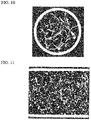
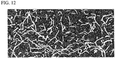
- CT images of No. 1 show a transverse cross-sectional view in FIG. 10 , a vertical cross-sectional view in FIG. 11 , and the inner-wall surface of the aluminum pipe in FIG. 12 .
- the porous aluminum sintered body is white portions excepting an outermost peripheral portion in FIG. 10 and upper and lower thick linear portions in FIG. 11 .
- more portions in which the porous aluminum sintered body is long exist than in FIG. 11 .
- FIG. 11 a lot of spots of the transvers cross section of the aluminum fibers appears in spots.
- the long portions of the porous aluminum body are bonded.
- a heat-exchange pipe in which the heat-exchange property is excellent and a metal porous body is not easily dropped off from the metal pipe can be provided.
Landscapes
- Engineering & Computer Science (AREA)
- Mechanical Engineering (AREA)
- Chemical & Material Sciences (AREA)
- Physics & Mathematics (AREA)
- Materials Engineering (AREA)
- Thermal Sciences (AREA)
- General Engineering & Computer Science (AREA)
- Manufacturing & Machinery (AREA)
- Organic Chemistry (AREA)
- Metallurgy (AREA)
- Composite Materials (AREA)
- Dispersion Chemistry (AREA)
- Geometry (AREA)
- Powder Metallurgy (AREA)
Abstract
Description
- The present invention relates to a heat-exchange pipe configured by bonding a porous body on an inner-wall surface of a pipe and a producing method thereof. Priority is claimed on
Japanese Patent Application No. 2020-041798, filed March 11, 2020 - As a heat-exchange pipe configured by bonding a porous body on an inner-wall surface of a pipe, for example as shown in
Patent Literature 1, a porous aluminum composite body in which a porous aluminum body is bonded on an inner peripheral surface of an aluminum pipe which is an aluminum bulk body is disclosed. The porous aluminum body inPatent Literature 1 is made by sintering a plurality of aluminum base substances to be integrated, and its porosity is set in a range of 30% or more and 90% or less. - The aluminum base substances are aluminum fibers and aluminum powder and have a structure which are bonded to each other by columnar projections protruding outward. In this case, it is described that a fiber diameter of the aluminum fibers is in a range of 20 µm or more and 1000 µm or less, and that three-dimensional and isotropic gaps are maintained between the aluminum fibers.
- Patent Literature 1:
Japanese Unexamined Patent Application, First Publication No. 2016-006226 - In the porous aluminum body described in Patent Literature, since the gaps between the aluminum fibers are isotropic and the fiber diameter of the aluminum fibers is small, a heat exchange with an inner-wall surface of the pipe (aluminum pipe) is restricted, so it is difficult to exchange the heat sufficiently between an outer surface of the pipe and the porous aluminum body. Moreover, if the bonding between the porous aluminum body and the pipe is not sufficient, the porous aluminum body may drop from the pipe.
- The present invention is achieved in consideration of the above circumstances, and has an object to provide a heat-exchange pipe having an excellent heat-exchange property and in which a metal porous body does not easily drop off from a metal pipe.
- A heat-exchange pipe of the present invention is provided with a metal pipe and a metal porous body which is configured by joining a plurality of metal fibers and bonded to an inner-wall surface of the metal pipe. At least some of the metal fibers are partially bonded to the inner-wall surface of the metal pipe for a length direction. The metal fibers which are bonded to the inner-wall surface bend on the inner-wall surface of the metal pipe and extend from the inner-wall surface to leave.
- Since some of the metal fibers which are in contact with the inner-wall surface of the metal pipe are bonded, the heat is exchanged between the metal pipe and the metal porous body in a whole of the bonded parts. Moreover, since the metal fibers extend from the inner-wall surface to leave from the bonded parts between the metal pipe and the metal porous body, the metal fibers can be arranged effectively in a center part of a cross-sectional surface of the metal pipe, so that the heat exchange with a fluid flowing in the metal pipe is favorably performed. Accordingly, this heat-exchange pipe is excellent in the heat-exchange property between the exterior and the interior of the pipe.
- Furthermore, since the metal fibers are bonded to the inner-wall surface at a part of the length direction not at an end part, there is no fear of dropping off from the metal pipe and it is possible to maintain the heat-exchange performance stably for a long time.
- As one aspect of the heat-exchange pipe, it is preferable that a bonding area ratio of the metal fibers to the inner-wall surface of the metal pipe be 5% or more.
- If the bonding area ratio is 5% or more, the metal fibers are sufficiently bonded to the inner-wall surface of the metal pipe, they do not drop off. If it is less than 5%, since the contact of the metal fibers to the inner-wall surface of the metal pipe is small, there is a risk that the heat exchange between the metal pipe and the metal fibers may be small.
- As another aspect of the heat-exchange pipe, a difference between an average area ratio of the metal fibers in a center part corresponding a half of an area of a transverse cross section of the metal pipe and an average area ratio of the metal fibers in a whole of the transverse cross section is preferably in 5% or less.
- In the metal porous body, the metal fibers are preferably arranged evenly in the cross section of the metal pipe. If the metal fibers are biased to be arranged to either of the center part or an inner peripheral wall part, a fluid is concentrated and flows in a part where the area ratio of the metal fibers is small in the cross section, and the heat-exchange performance may be deteriorated. If the difference between the average area ratio in the center part of the cross section and the average area ratio in the whole cross section of the metal pipe is 5% or less, the fluid flows in the whole cross section of the metal pipe, and the heat is exchanged effectively with the metal fibers.
- A producing method of a heat-exchange pipe of the present invention has a precursor formation step of stacking a plurality of metal fibers to form a precursor, an in-pipe charging step of pushing the precursor from one end of the metal pipe to charge into the metal pipe, and a sintering step of sintering the metal pipe in a state of charging the precursor; the precursor before the in-pipe charging step is formed such that an outer diameter in a state where the metal fibers are stacked is larger than an inner diameter of the metal pipe.
- By forming the outer diameter of the precursor larger than the inner diameter of the metal pipe, when the precursor is pushed into the metal pipe, the metal fibers disposed on the outer peripheral part of the precursor is bent, and is in contact with the inner-wall surface of the metal pipe along the length direction. In the outer peripheral part of the precursor, the metal fibers are provided in a state of being bent at the inner-wall surface of the metal pipe and then extending to leave from the inner-wall surface. Accordingly, since the metal fibers are partially bonded to the inner-wall surface of the metal pipe and arranged to extend in a cross-sectional direction, it is possible to produce the heat-exchange pipe having an excellent heat-exchange property.
- According to the present invention, it is possible to provide a heat-exchange pipe with an excellent heat-exchange property and in which the metal porous body is not easily dropped off from the metal pipe.
-
- [
FIG. 1 ] It is a longitudinal cross-sectional view of a heat-exchange pipe of an embodiment according to the present invention. - [
FIG. 2 ] It is a transverse cross-sectional view taken along the line A-A inFIG. 1 . - [
FIG. 3 ] It is a flowchart showing an embodiment of a producing method of the present invention. - [
FIG. 4 ] It is a schematic view of a metal porous body (porous aluminum sintered body). - [
FIG. 5 ] It is a schematic view of an aluminum material for sintering. - [
FIG. 6 ] It is a schematic view showing a state in which columnar projections are made in the aluminum material for sintering. - [
FIG. 7 ] It is a schematic view showing a state of the columnar projections. - [
FIG. 8 ] It is a schematic view showing a step of forming a precursor. - [
FIG. 9 ] It is a schematic view showing a state in which the precursor is pushed into an aluminum pipe. The left part surrounded by a circle is an enlarged view of a principal part. - [
FIG. 10 ] It is a CT image of a transverse section of the heat-exchange pipe. - [
FIG. 11 ] It is a CT image of a longitudinal section of the heat-exchange pipe. - [
FIG. 12 ] It is a CT image showing a bonded part of a porous aluminum sintered body on an inner-wall surface of the aluminum pipe. - An embodiment of the present invention will be explained below. A heat-
exchange pipe 10 of this embodiment is, as shown inFIG. 1 and FIG. 2 , configured from an aluminum pipe (corresponding to a metal pipe of the present invention) 20 made of aluminum or aluminum alloy and a porous aluminum sintered body (corresponding to a metal porous body of the present invention: herein after "a porous body") 30 made of aluminum or aluminum alloy, charged in thealuminum pipe 20. - In the heat-
exchange pipe 10, a heat source (not illustrated) which is high temperature or low temperature is provided outside a portion where theporous body 30 is charged; a gas or liquid fluid as a heat-transfer medium is flowed inside thealuminum pipe 20, and the fluid changes heat with the heat source when passing in theporous body 30. - The
aluminum pipe 20 is an ordinary pipe having a circular cross section formed by extrusion molding or the like of Al-Mn type alloy or the like such as A3003. Thealuminum pipe 20 has, for example, 5 mm to 150 mm of an outer diameter and 0.8 mm to 10 mm of a wall thickness. - The
porous body 30 is, as shown inFIG. 4 , integrated by sintering a plurality of aluminum base substances (metal substances) 31; a porosity is set in a range of 30% or more and 90% or less. As thealuminum base substances 31, a mixture ofaluminum fibers 31a (metal fibers) andaluminum powder particles 31b is used. - On outer surfaces of the
aluminum base substances 31, a plurality ofcolumnar projections 32 protruding outward are formed; the plurality of thealuminum base substances 31 are joined by base substancejoint parts 35. The basesubstance joint parts 35 are parts where thecolumnar projections 32 are joined to each other, parts where thecolumnar projections 32 and surfaces of thealuminum base substances 31 are joined, and parts where the surfaces of thealuminum base substances 31 are joined to each other. - In the base substance
joint parts 35,eutectic element compounds 17 containing Ti-Al type compounds 16 and eutectic elements that eutectic-reactions with Al exist. In this embodiment, the Ti-Al type compounds 16 are compounds of Ti and Al: more specifically, they are Al3Ti intermetallic compounds. - As the eutectic elements that eutectic-react with Al, for example, Ag, Au, Ba, Be, Bi, Ca, Cd, Ce, Co, Cu, Fe, Ga, Gd, Ge, In, La, Li, Mg, Mn, Nd, Ni, Pd, Pt, Ru, Sb, Si, Sm, Sn, Sr, Te, Y, Zn, and the like, are exemplified. Among them, Ni, Mg, Cu, and Si are preferable.
- In this
porous body 30, thealuminum base substances 31 are bonded to either or both the otheraluminum base substances 31 or the inner-wall surface of thealuminum pipe 20. - The
aluminum fibers 31a joined to the inner-wall surface of thealuminum pipe 20 are joined in a state of being in contact along the length direction for a range of a prescribed length (in other words, thealuminum fibers 31a are joined at a part in the length direction to the inner-wall surface); the middle of thealuminum fibers 31a are bended on the inner-wall surface of thealuminum pipe 20, and the rest which is not in contact with the inner-wall surface extends and leaves from the inner-wall surface. - It is preferable that the
aluminum fibers 31a be bended at right angle to the joined part to the inner-wall surface of thealuminum pipe 20 and extend perpendicular from the inner-wall surface of thealuminum pipe 20. However, if they are separated from the inner-wall surface of thealuminum pipe 20, it is not necessary to be perpendicular to the inner-wall surface. Moreover, it is applicable that onealuminum fiber 31a that is joined in a state of being in contact at two or more portions to the inner-wall surface of thealuminum pipe 20 exists. - Since the
aluminum fibers 31a are joined to the inner-wall surface of thealuminum pipe 20 in a state of being in contact in the range of the prescribed length, a joined area (total area) of thealuminum fibers 31a to thealuminum pipe 20 is preferably 5% or more to an area of the inner-wall surface of thealuminum pipe 20 in a region E where theporous body 30 is provided. - That is, in the region E where the
porous body 30 is provided, where a bonding area ratio to the wall surface is a percentage of (the joined area of thealuminum fibers 31 a)/(the area of the inner-wall surface of the aluminum pipe 20), it is preferable that the bonding area ratio ≥ 5%. If the bonding area ratio is less than 5%, thealuminum fibers 31a are weakly joined to thealuminum pipe 20 and dropped off from the joined part, so that the heat transference is deteriorated and there is a risk that theporous body 30 is dropped off from the inner-wall surface of thealuminum pipe 20. - Since the
porous body 30 does not perform effective heat transfer if thealuminum base substances 31 are unevenly distributed near the inner-wall surface of thealuminum pipe 20, it is preferable that thealuminum base substances 31 are arranged to be dispersed throughout the cross-sectional area of thealuminum pipe 20. - Specifically, as shown in
FIG. 2 , a difference between an average area ratio of thealuminum fibers 31a in a region F of a center part corresponding a half of an area of the cross section of thealuminum pipe 20 and an average area ratio of thealuminum fibers 31a in a region G of the entire cross section is 5% or less. If the difference of the average area ratios exceeds 5%, in theporous body 30, thealuminum base substances 31 may be unevenly distributed on the inner-wall surface of thealuminum pipe 20. - There are portions where the
aluminum base substances 31 and the inner-wall surface of thealuminum pipe 20 are joined via thecolumnar projections 32. In the joined portions, the above-described eutectic element compounds 17 are present, containing Ti-Al type compounds 16 and eutectic elements that eutectic-react with Al. - Next, a producing method of the heat-
exchange pipe 10 of the present embodiment will be explained.FIG. 3 shows the flowchart. - As the
aluminum base substances 31, as described above, thealuminum fibers 31a and thealuminum powder particles 31b are used. - Here, the
aluminum fibers 31a of thealuminum base substances 31 are made by a melt-spinning method. That is, a material made of aluminum or aluminum alloy is heated and melted, and extruded from a nozzle into the air or water at a constant rate to cool and solidify it; and it is cut at a prescribed length. - A fiber diameter R of the
aluminum fibers 31a is in a range of 20 µm or more and 1000 µm or less; preferably, in a range of 50 µm or more and 500 µm or less. A fiber length L of thealuminum fibers 31a is in a range of 0.2 mm or more and 100 mm or less; preferably, in a range of 1 mm or more and 50 mm or less. - The
aluminum fibers 31a can be in a range of 4 or more and 2500 or less of a rate L/R between the length L and the fiber diameter R, for example. - If the fiber diameter R of the
aluminum fibers 31a is less than 20 µm, the joined area between the aluminum fibers to each other is small, and a sintering strength may be insufficient. On the other, if the fiber diameter R of thealuminum fibers 31a exceeds 1000 µm, the number of contact points where the aluminum fibers are in contact with each other lacks and the sintering strength may also lack. - If the ratio L/R between the length L and the fiber diameter R of the
aluminum fibers 31a is less than four, when thealuminum fibers 31a are piled and arranged in the producing method of the porous aluminum sintered body, it is difficult to make a bulk density DP of theporous body 30 to be 50% or less of a true density DT of the aluminum fibers, and it may be difficult to obtain theporous body 30 having the high porosity. On the other, if the ratio L/R between the length L and the diameter R of thealuminum fibers 31a exceeds 2500, the aluminum fibers cannot be dispersed evenly, and there may be a risk that theporous body 30 having the even porosity is not easily obtained. - In order to further increase the porosity, the ratio L/R between the length L and the fiber diameter R of the
aluminum fibers 31a is preferably 10 or more. In order to obtain theporous body 30 having a more uniform porosity, the ratio L/R between the length L and the diameter R of thealuminum fibers 31a is preferably 500 or less. - Atomized powder can be used as the
aluminum powder particles 31b. A particle diameter of thealuminum powder particles 31b is in a range of 5 µm or more and 500 µm or less, preferably in a range of 20 µm or more and 200 µm or less. - By adjusting a mixing ratio of the
aluminum fibers 31a and thealuminum powder particles 31b, the porosity can be adjusted. That is, by increasing the ratio of the ratio of thealuminum fibers 31a, the porosity of theporous body 30 can be increased. For example, it is preferable that the ratio of thealuminum powder particles 31b be 15% by mass or less and the ratio of thealuminum fibers 31a be 85% by mass or more in thealuminum base substances 31. - As the
aluminum fibers 31a and thealuminum powder particles 31b, other than pure aluminum, aluminum alloy may be used. For example, aluminum base substances made of A3003 alloy (Al-0.6% by mass of Si-0.7% by mass of Fe-0.1% by mass of Cu-1.5% by mass of Mn-0.1 % by mass of Zn alloy), A5052 alloy (Al-0.25% by mass of Si-0.40% by mass of Fe- 0.10% by mass of Cu- 0.10% by mass of Mn-2.5% by mass of Mg alloy-0.2% by mass Cr-0.1% by mass of Zn alloy) that are regulated by JIS or the like can be suitably used. - It is not necessary that the
aluminum fibers 31a and thealuminum powder particles 31b have the same composition. For example, thealuminum fibers 31a made of pure aluminum and thealuminum powder particles 31b made of JIS A3003alloy can be appropriately adjusted in accordance with the purpose. -
Titanium powder particles 42 and eutecticelement powder particles 43 are fixed to thealuminum base substances 31 composed of thealuminum fibers 31a and thealuminum powder particles 31b configured as described above to make analuminum material 40 for sintering. - The
aluminum material 40 for sintering includes, as shown inFIG. 5 , the aluminum base substances 31 (inFIG. 5 FIG. 6 , thealuminum fiber 31a is shown in the left and thealuminum powder particle 31b is shown in the right) and the plurality oftitanium powder particles 42 and the eutectic-element powder particles (nickel powder particles, magnesium powder particles, copper powder particles, and silicon powder particles) 43 fixed on the outer surface of thealuminum base substances 31. - As the
titanium powder particles 42, either one of or both metal-titanium powder particles and titanium hydride powder particles can be used. As the eutectic-element powder particles 43, metal-nickel powder particles, metal-magnesium powder particles, metal-copper powder particles, metal-silicon powder particles, and alloy powder of these are used. - In the
aluminum material 40 for sintering, a content of thetitanium powder particles 42 is in a range of 0.01% by mass or more and 20% by mass or less. - A particle diameter of the
titanium powder particles 42 is in a range of 1 µm or more and 50 µm or less, preferably in a range of 5 µm or more and 30 µm or less. Since the particle diameter of the titanium hydride powder particles can be made smaller than the metal titanium powder particles, it is preferable to use the titanium hydride powder particles in a case of making the particle diameter of thetitanium powder particles 42 fixed on the outer surface of thealuminum base substrates 31 minute. - Gaps between the
titanium powder particles aluminum base substances 31 are preferably in a range of 5 µm or more and 100 µm or less. - Contents of components of the eutectic-
element powder particles 43 in thealuminum material 40 for sintering are as followings: the nickel powder particles are in a range of 0.01% by mass or more and 5.0% by mass or less, the magnesium powder particles are in a range of 0.01% by mass or more and 5.0% by mass or less, the copper powder particles are in a range of 0.01% by mass or more and 5.0% or less, and the silicon powder particles are in a range of 0.01% by mass or more and 15.0% by mass or less. - The nickel powder particles are in a range of 1 µm or more and 20 µm or less, preferably in a range of 2 µm or more and 10 µm or less. The magnesium powder particles are in a range of 20 µm or more and 500 µm or less, preferably in a range of 20 µm or more and 100 µm or less. The copper powder particles are in a range of 5 µm or more and 500 µm or less, preferably in a range of 20 µm or more and 100 µm or less. The silicon powder particles are in a range of 5 µm or more and 200 µm or less, preferably in a range of 10 µm or more and 100 µm or less.
- As shown in
FIG. 3 , steps are carried out in order. First, in the normal temperature, thealuminum base substances 31 composed of thealuminum fibers 31a and thealuminum powder particles 31b, thetitanium powder particles 42, and the eutectic-element powder particles (e.g., the nickel powder particles, the magnesium powder particles, the copper powder particles, and the silicon powder particles) 43 are mixed (a mixing step). - At this time, a binder solution is sprayed. As a binder, it is preferable to be burned and resolved when it is heated to 500°C in the air: in particular, it is preferable to use an acrylic resin and a cellulose polymer. As a solvent of the binder, various solvents such as an aqueous solvent, an alcohols solvent, or an organic solvent can be used.
- In this mixing step, for example, using various blenders such as an automatic mortar, a pan-type oscillating granulator, a shaker mixer, a pot mill, a high-speed mixer, a V-type mixer or the like, the
aluminum base substances 31, thetitanium powder particles 42, and the eutectic-element powder particles 43 are mixed while fluidizing. - Next, a mixture which is obtained in the mixing step is dried (a drying step). By the mixing step and the drying step, on the
aluminum base substances 31 shown in the upper part ofFIG. 5 that is composed of thealuminum fibers 31a and thealuminum powder particles 31b, thetitanium powder particles 42 and the eutectic-element powder particles 43 are dispersed and fixed as shown in the lower part, to produce thealuminum material 40 for sintering which is the present embodiment. - Next, the
aluminum material 40 for sintering is sprayed into acylindrical carbon container 50 shown inFIG. 8 and filled without adding pressure (a material-spraying step). Thecarbon container 50 includes, for example, acylindrical body 51 and abottom lid 52 that can open and close a bottom part of thecylindrical body 51. Thecylindrical body 51 is formed to have an inner diameter larger than an inner diameter of thealuminum pipe 20. - By spraying the
aluminum material 40 for sintering on thebottom lid 52, the aluminum fibers 30a of thealuminum base substances 31 are arranged so that most of the aluminum fibers 30a lie on thebottom lid 52, in other words, substantially in parallel with a surface of thebottom lid 52, and is sequentially piled from below. - In a state in which the
aluminum material 40 for sintering is filled up to a predetermined height in thecarbon container 50, they are charged into a degreasing furnace and heated in the atmosphere to remove the binder (a binder removal step). - The process from the mixing step to the binder removal step explained above is a precursor formation step.
- Then, the
aluminum material 40 for sintering is taken out from thecarbon container 50 and filled in the aluminum pipe 20 (an in-pipe charging step). Thealuminum material 40 for sintering becomes a state of mutually fixed in thecarbon container 50 in the binder removal step; by being taken out from thecarbon container 50, it becomes aprecursor 41 having a disc shape or a columnar shape in accordance with the filled height. Theprecursor 41 has an outer diameter larger than the inner diameter of thealuminum pipe 20. The outer diameter is preferably larger than the inner diameter of thealuminum pipe 20 at 1 mm or more and 10 mm or less, for example. - Since the
precursor 41 has the larger outer diameter than the inner diameter of thealuminum pipe 20, as shown inFIG. 9 , using a push-inrod 53, when theprecursor 41 is loaded into thealuminum pipe 20 so as to pushing theprecursor 41 from one end of thealuminum pipe 20, as shown in a double-dotted chain lines inFIG. 9 , an outer peripheral part of theprecursor 41 is bended at substantially orthogonal on the inner-wall surface of thealuminum pipe 20, and the outer peripheral part that is bended is in close contact with the inner-wall surface of thealuminum pipe 20. - On the contact portions to the inner-wall surface of the
aluminum pipe 20, thealuminum fibers 31a of theprecursor 41 is in contact substantially along an axial direction of thealuminum pipe 20. Inside thealuminum pipe 20, thealuminum fibers 31a leave from the inner-wall surface of thealuminum pipe 20 and extend along substantially a cross sectional direction of thealuminum pipe 20. - Although a thickness of the
precursor 41 may be a lump of a size corresponding to a loading region E of theporous body 30 provided in thealuminum pipe 20 in the heat-exchange pipe 10 as a product, a plurality ofprecursors 41 having a thickness smaller than a thickness of a final product may be prepared for one product, or a plurality of theprecursors 41 may be pushed into thealuminum pipe 20 one by one, or a plurality of theprecursors 41 may be pushed into thealuminum pipe 20 to be loaded. - Thereafter, the
aluminum pipe 20 loaded with theprecursor 41 is charged in a sintering furnace in at an inert gas atmosphere, and held in a temperature range of 575 to 665°C for 0.5 to 60 minutes in accordance with the kind and addition amount of the added eutectic-element powder particles 43 (sintering step). The retention time is preferably 1 to 20 minutes. - In the sintering step, although the
aluminum base substances 31 in thealuminum material 40 for sintering formed into theprecursor 41 is melted, since oxide films are formed on the surface of the aluminum base substances, the melted aluminum is held by the oxide films and the shape of thealuminum base substances 31 is maintained. - In portions of the outer surface of the
aluminum base substances 31 where thetitanium powder particles 42 are fixed, the oxide films are broken by the reaction with titanium, and the melted aluminum inside is ejected outward. The ejected melted aluminum generates a compound having a high melting point and is solidified by the reaction with titanium. - As a result, as shown in the lower stage of
FIG. 6 , a plurality ofcolumnar projections 32 are formed on the outer surface of thealuminum base substances 31. In thecolumnar projection 32, a Ti-Al type compound 16 is present; and growth of thecolumnar projections 32 more than necessary is suppressed by the Ti-Al type compound 16. - In a case of using titanium hydride as the
titanium powder particles 42, the titanium hydride is decomposed at about 300 to 400°C, and the generated titanium reacts with the oxide film on the surface of thealuminum base substances 31. - In the present embodiment, by the eutectic-
element powder particles 43 fixed on the outer surface of thealuminum base substances 31, portions where the melting point falls down are locally formed on thealuminum base substances 31. Accordingly, in accordance with the types and the addition amount of the added eutectic-element powder particles 43, even under a condition of comparative low temperature such as 575 to 655°C, thecolumnar projections 32 are reliably formed. - The adjacent
aluminum base substances columnar projections 32 of each other by integrated in a melted state or solid-phase sintered, and theporous body 30 in which the plurality of thealuminum base substances columnar projections 32 is produced as shown inFIG. 4 . - In the base substance
joint parts 35 where thealuminum base substances columnar projections 32, as shown inFIG. 7 , the Ti-Al type compound (Al3Ti intermetallic compound) 16 and the eutectic-element compound 17 exist. - On the inner-wall surface of the
aluminum pipe 20, theprecursor 41 is bended and in contact at the outer peripheral part, some of thealuminum fibers 31a of thealuminum base substances 31 are in contact along the length direction, and thealuminum fibers 31a and thealuminum pipe 20 are joined by sintering in this state. Accordingly, thealuminum fibers 31a are joined in a state of being in linearly contact. - Some of the
columnar projections 32 of thealuminum base substances 31 are also joined to thealuminum pipe 20. In a case in which thetitanium powder particles 42 and the eutectic-element powder particles 43 are in contact with the surface of thealuminum pipe 20, thecolumnar projections 32 are formed also from the surface of thealuminum pipe 20, and thealuminum pipe 20 and theporous body 30 are joined. - In the heat-
exchange pipe 10 having above-described structure, since thealuminum fibers 31a of theporous body 30 are bended on the inner-wall surface of thealuminum pipe 20 and some of them are joined to the inner-wall surface of thealuminum pipe 20 in a state of being in linearly contact, the heat exchange is rapidly carried out between theporous body 30 and the inner-wall surface. - In the inside of the
aluminum pipe 20, since thealuminum fibers 31a extend toward a direction leaving from the inner-wall surface of thealuminum pipe 20, e.g., along the radial direction, the heat-exchange performance with the heat-transfer medium is also excellent. - Moreover, since the
aluminum fibers 31a are joined on the inner-wall surface of thealuminum pipe 20 in the state of being in contact along the length direction, it is not easily peeled off from thealuminum pipe 20, and it is possible to maintain the heat-exchange performance stably for a long time. - Since the Ti-
Al type compound 16 exists in the portion which is joined by thecolumnar projections 32, the oxide films on the surface of thealuminum pipe 20 and theporous body 30 are removed by this Ti-Al type compound 16, so that the joining strength between thealuminum pipe 20 or theporous bodies 30 themselves is improved. - Furthermore, since growth of the
columnar projections 32 is restrained by the Ti-Al type compound 16, it can be restrained that the melted aluminum from ejecting to theporous body 30 to maintain the porosity of theporous body 30. - Particularly, in the present embodiment, since Al3Ti exists as the Ti-
Al type compound 16, the oxide film formed on the surface of thealuminum pipe 20 and theporous body 30 is reliably removed, and it is possible to drastically improve the joining strength between thealuminum pipe 20 and theporous body 30. - In the present embodiment, since the eutectic-
element compound 17 exists in thecolumnar projections 32, the melting point of thealuminum base substances 31 is partially reduced so that thecolumnar projections 32 tend to be formed thick; as a result, the joining strength between thealuminum pipe 20 and theporous body 30 can be further improved. - In the present embodiment, since the content of the
titanium powder particles 42 is 0.01% by mass or more and 20% by mass or less in thealuminum material 40 for sintering, thecolumnar projections 32 can be formed with appropriate intervals on the outer surface of thealuminum base substances 31, so it is possible to reliably join thealuminum pipe 20 and theporous body 30. - In the present embodiment, since the interval between the plurality of
titanium powder particles aluminum base substances 31 is in a range of 5 µm or more and 100 µm, the interval between thecolumnar projections 32 is appropriate, and it is possible to obtain theporous body 30 having sufficient strength and high porosity. - In the present embodiment, since the content of the eutectic-
element powder particles 43 are in a range of 0.01% by mass or more and 5.0 % by mass or less, the magnesium powder particle are in a range of 0.01% by mass or more and 5.0% by mass or less, the copper powder particles are in a range of 0.01% by mass or more and 5.0% by mass or less, and the silicon powder particles are in a range of 0.01% by mass or more and 15.0% by mass or less in thealuminum material 40 for sintering; accordingly, the portions where the melting point is partially reduced in thealuminum base substances 31 can be formed with the appropriate intervals and the unnecessary melted aluminum can be restrained from flowing out, so it is possible to obtain theporous body 30 having the sufficient strength and the high porosity. - In accordance with the kinds and the addition amount of the added eutectic-element powder particles, the
columnar projections 32 is reliably formed even in the comparatively low temperature condition such as 575 to 665°C, so that the temperature condition for the sintering step can be set low. - In the present embodiment, since the
aluminum fibers 31a and thealuminum powder particles 31b are used as thealuminum base substances 31, by adjusting the mixture ratio of them, the porosity of theporous body 30 can be controlled. - The
porous body 30 of the present embodiment has the porosity in a range of 30% or more and 90% or less, so that a surface area of a porous aluminumcomposite body 10 used as a heat-transfer member can be maintained, and the heat-transfer efficiency can be drastically improved. - The present invention is not limited to the above-described embodiments and various modifications may be made without departing from the scope of the present invention.
- For example, in the above embodiment, the pipe is made of aluminum and loaded with the porous aluminum sintered body having the aluminum fibers and aluminum powder; however, it is not limited to aluminum and various metals which can be sintered can be used. In the present invention, a metal porous body in which a plurality of metal fibers are joined is bonded to the metal pipe.
- Although the metal porous body is configured from a mixed body of the metal fibers and the metal powder in the above-described embodiment, the metal porous body may be formed from only the metal fibers. In that case, the metal fibers are mutually joined by sintering and the metal-wire fibers and the inner-wall surface of the metal pipe are bonded.
- The metal pipe is not limited to have the circular cross section, but the cross section may be polygon or the like.
- An aluminum pipe that is made of JIS A3003 aluminum alloy; aluminum fibers and aluminum powder as aluminum base substances; titanium powder; and Mg powder as eutectic-element powder were prepared. An inner diameter of the aluminum pipe was 18 mm. Many kinds of the aluminum fibers were manufactured in a range of 300 µm of a diameter and 10 mm to 25 mm of a length.
- Aluminum material for sintering was produced by mixing the aluminum base substances, the titanium powder and the eutectic-element powder, and a precursor of disk shape with a diameter 22 mm was produced. The precursor was pushed into the aluminum pipe, and then they were sintered at 600°C for 30 minutes, to produce a heat-exchange pipe in which the porous aluminum sintered body was joined on the aluminum pipe in a range of a predetermined length was produced.
- An X-ray CT (computed tomography) image of the cross section of the obtained heat-exchange pipe was analyzed using an image processing software (ExFact VR 2.1 made by Nihon Visual Science, Inc.) as follows.
- An average area ratio occupied by the porous aluminum sintered body in the whole cross section and an average area ratio occupied by the porous body in the center part region of the cross section were measured. Regarding the cross section, using an orthogonal cross-sectional function of the software, an average value of results of extracting 36 images at about 0.7 mm intervals and analyzing them was shown.
- For a bonding area ratio of the porous aluminum sintered body on the inner-wall surface of the aluminum pipe, using a cylindrical panoramic function of the software, cylindrical panoramic images of portions where the porous aluminum sintered body and the aluminum pipe are joined were extracted, and a ratio of an area occupied by the portions where the porous aluminum sintered body was joined for the whole area was measured.
- Furthermore, a columnar rod having an outer diameter 14 mm was inserted into the aluminum pipe, it was observed whether the porous aluminum sintered body was peeled from the aluminum pipe and dropped off by adding 10 N of force.
- These results are shown in Table 1.
[Table 1] No. CROSS SECTION AVERAGE AREA RATIO (%) WALL SURFACE BONDING AREA RATIO (%) PEEL OFF OBSERVATION WHOLE CENTER PART 1 20.0 23.6 19.0 NO 2 20.2 15.4 12.4 NO 3 19.1 16.6 6.4 NO 4 20.5 25.4 2.0 SLIGHTLY PEELED 5 10.3 11.2 9.3 NO 6 9.8 13.5 6.1 NO 7 8.9 13.2 1.2 SLIGHTLY PEELED 8 27.6 22.9 32.1 NO 9 29.7 28.5 24.5 NO 10 28.5 29.9 11.1 NO 11 27.9 29.7 4.5 SLIGHTLY PEELED - Although there were some slight peelings in the drop-off test of the porous aluminum body, this is a severe test which is impossible in a normal flowing of a fluid, and it is considered not to be a practical problem. Moreover, if it is firmly bonded on the aluminum pipe like this, the heat-exchange property is also considered to be excellent.
- CT images of No. 1 show a transverse cross-sectional view in
FIG. 10 , a vertical cross-sectional view inFIG. 11 , and the inner-wall surface of the aluminum pipe inFIG. 12 . In these drawings, the porous aluminum sintered body is white portions excepting an outermost peripheral portion inFIG. 10 and upper and lower thick linear portions inFIG. 11 . InFIG. 10 , more portions in which the porous aluminum sintered body is long (the aluminum fibers) exist than inFIG. 11 . InFIG. 11 , a lot of spots of the transvers cross section of the aluminum fibers appears in spots. Moreover, as seen fromFIG. 12 , also on the inner-wall surface of the aluminum pipe, the long portions of the porous aluminum body (the aluminum fibers) are bonded. - A heat-exchange pipe in which the heat-exchange property is excellent and a metal porous body is not easily dropped off from the metal pipe can be provided.
-
- 10
- Heat-exchange pipe
- 20
- Aluminum pipe (Metal pipe)
- 30
- Porous aluminum sintered body (Metal porous body)
- 31
- Aluminum base substance
- 31a
- Aluminum fiber
- 31b
- Aluminum powder
- 40
- Aluminum material for sintering
- 41
- Precursor
- 50
- Carbon container
- 53
- Push-in rod
Claims (12)
- A heat-exchange pipe comprisinga metal pipe anda metal porous body which is configured by joining a plurality of metal fibers and bonded to an inner-wall surface of the metal pipe, whereinat least some of the metal fibers are partially bonded to the inner-wall surface of the metal pipe for a length direction, and the metal fibers which are bonded to the inner-wall surface bend on the inner-wall surface of the metal pipe and extend from the inner-wall surface to leave.
- The heat-exchange pipe according to claim 1, wherein a bonding area ratio of the metal fibers to the inner-wall surface of the metal pipe is 5% or more.
- The heat-exchange pipe according to claim 1, wherein in a transverse cross section across an axis of the metal pipe, a difference between an average area ratio of the metal fibers in a center part corresponding a half of an area of the metal porous body and an average area ratio of the metal fibers in a whole of the transverse cross section is 5% or less.
- A producing method of a heat-exchange pipe, comprisinga precursor formation step of stacking a plurality of metal fibers to form a precursor,an in-pipe charging step of pushing the precursor from one end of a metal pipe to charge into the metal pipe, anda sintering step of sintering the metal pipe in a state of charging the precursor,wherein
the precursor before the in-pipe charging step is formed such that an outer diameter in a state where the metal fibers are stacked is larger than an inner diameter of the metal pipe. - The heat-exchange pipe according to claim 2, wherein in a transverse cross section across an axis of the metal pipe, a difference between an average area ratio of the metal fibers in a center part corresponding a half of an area of the metal porous body and an average area ratio of the metal fibers in a whole of the transverse cross section is 5% or less.
- The heat-exchange pipe according to claim 1 wherein the metal porous body further includes metal powder particles bonded to the metal fibers.
- A heat-exchange pipe comprisinga metal pipe, anda porous body which is configured by sintering a plurality of metal base substances and bonded to an inner-wall surface of the metal pipe, whereinthe metal base substances includes metal fibers, and the metal fibers bonded to the inner-wall surface partially leave from the inner-wall surface.
- The heat-exchange pipe according to claim 7 wherein the metal base substances further include metal powder particles.
- The heat-exchange pipe according to claim 8 wherein a ratio of the metal powder particles in the metal base substances is 15% by mass or less.
- The heat-exchange pipe according to claim 8 wherein a particle diameter of the metal powder particles is 5 µm or more and 500 µm or less.
- The heat-exchange pipe according to claim 7 wherein the metal base substances are made of aluminum or aluminum alloy, and are joined by a base substance joint part contains a eutectic-element compound including eutectic element that eutectic-reactions with Ti-Al type compounds and Al.
- The heat-exchange pipe according to claim 7, wherein a ratio L/R between a length L and a fiber diameter R of the metal fibers I 10 or more and 500 or less.
Applications Claiming Priority (2)
| Application Number | Priority Date | Filing Date | Title |
|---|---|---|---|
| JP2020041798A JP2021143366A (en) | 2020-03-11 | 2020-03-11 | Heat exchange pipe and its manufacturing method |
| PCT/JP2021/006554 WO2021182086A1 (en) | 2020-03-11 | 2021-02-22 | Heat-exchange pipe and manufacturing method thereof |
Publications (2)
| Publication Number | Publication Date |
|---|---|
| EP4119261A1 true EP4119261A1 (en) | 2023-01-18 |
| EP4119261A4 EP4119261A4 (en) | 2024-04-10 |
Family
ID=77671442
Family Applications (1)
| Application Number | Title | Priority Date | Filing Date |
|---|---|---|---|
| EP21768556.9A Withdrawn EP4119261A4 (en) | 2020-03-11 | 2021-02-22 | Heat-exchange pipe and manufacturing method thereof |
Country Status (5)
| Country | Link |
|---|---|
| US (1) | US20230097167A1 (en) |
| EP (1) | EP4119261A4 (en) |
| JP (1) | JP2021143366A (en) |
| CN (1) | CN115190961A (en) |
| WO (1) | WO2021182086A1 (en) |
Families Citing this family (3)
| Publication number | Priority date | Publication date | Assignee | Title |
|---|---|---|---|---|
| KR102771228B1 (en) * | 2020-02-19 | 2025-02-20 | 가부시키가이샤 도모에가와 코퍼레이션 | heat exchanger |
| JP2022141175A (en) * | 2021-03-15 | 2022-09-29 | 三菱マテリアル株式会社 | Pipe for heat exchange, and production method of the same |
| JPWO2024210164A1 (en) * | 2023-04-05 | 2024-10-10 |
Family Cites Families (7)
| Publication number | Priority date | Publication date | Assignee | Title |
|---|---|---|---|---|
| JP2003126228A (en) * | 2001-10-29 | 2003-05-07 | Kogi Corp | Deodorizing device |
| JP5606690B2 (en) * | 2009-06-23 | 2014-10-15 | 太盛工業株式会社 | Aluminum fiber porous sintered compact and manufacturing method thereof |
| JP6488875B2 (en) * | 2014-05-16 | 2019-03-27 | 三菱マテリアル株式会社 | Porous aluminum sintered body and method for producing porous aluminum sintered body |
| JP6477254B2 (en) | 2014-05-30 | 2019-03-06 | 三菱マテリアル株式会社 | Porous aluminum composite and method for producing porous aluminum composite |
| JP6237500B2 (en) * | 2014-07-02 | 2017-11-29 | 三菱マテリアル株式会社 | Porous aluminum heat exchange member |
| JP6724801B2 (en) * | 2017-01-18 | 2020-07-15 | 三菱マテリアル株式会社 | Copper porous body, copper porous composite member, method for producing copper porous body, and method for producing copper porous composite member |
| JP6823152B2 (en) | 2019-12-20 | 2021-01-27 | 日立グローバルライフソリューションズ株式会社 | Cooker |
-
2020
- 2020-03-11 JP JP2020041798A patent/JP2021143366A/en active Pending
-
2021
- 2021-02-22 US US17/908,982 patent/US20230097167A1/en not_active Abandoned
- 2021-02-22 EP EP21768556.9A patent/EP4119261A4/en not_active Withdrawn
- 2021-02-22 CN CN202180017623.8A patent/CN115190961A/en active Pending
- 2021-02-22 WO PCT/JP2021/006554 patent/WO2021182086A1/en not_active Ceased
Also Published As
| Publication number | Publication date |
|---|---|
| US20230097167A1 (en) | 2023-03-30 |
| EP4119261A4 (en) | 2024-04-10 |
| WO2021182086A1 (en) | 2021-09-16 |
| JP2021143366A (en) | 2021-09-24 |
| CN115190961A (en) | 2022-10-14 |
Similar Documents
| Publication | Publication Date | Title |
|---|---|---|
| US20230097167A1 (en) | Heat-exchange pipe and producing method thereof | |
| EP3165864B1 (en) | Porous aluminum heat exchange member | |
| EP3150305B1 (en) | Porous aluminum composite and method for manufacturing porous aluminum composite | |
| EP1632955A1 (en) | Aluminum based neutron absorber and method for production thereof | |
| JP6488876B2 (en) | Porous aluminum sintered body and method for producing porous aluminum sintered body | |
| DE102007044918A1 (en) | Hydrogen-permeable membranes of metallic composite material | |
| EP3144083B1 (en) | Porous aluminum sintered body and method for producing porous aluminum sintered body | |
| US4323395A (en) | Powder metallurgy process and product | |
| CN116134607A (en) | Bonded body, circuit board, semiconductor device, and method for manufacturing the bonded body | |
| EP3213839B1 (en) | Porous aluminum sintered body and method for producing porous aluminum sintered body | |
| US7503958B2 (en) | Method of manufacturing the SnZnNiCu solder powder and the SnZnNiCu solder powder | |
| JP2022141175A (en) | Pipe for heat exchange, and production method of the same | |
| JP2000336408A (en) | Method and apparatus for producing nickel powder for multilayer ceramic capacitor electrode | |
| JPH0354182A (en) | Graphite metallization method and parts using this method | |
| EP2944378A1 (en) | Catalytically active porous element and method for manufacturing the same | |
| JP6459725B2 (en) | Porous aluminum sintered body, porous aluminum composite member, method for producing porous aluminum sintered body, method for producing porous aluminum composite member | |
| EP4530003A1 (en) | Powder material for additive manufacturing and method for manufacturing additive-manufactured product using powder material | |
| EP4257267A1 (en) | Method for producing aluminum-containing particles | |
| KR20000063018A (en) | Method for forming composite vapor-deposited films with varied compositions formed in the initial and final stages of deposition, composite vapor-deposition material for the film and method for manufature thereof |
Legal Events
| Date | Code | Title | Description |
|---|---|---|---|
| STAA | Information on the status of an ep patent application or granted ep patent |
Free format text: STATUS: THE INTERNATIONAL PUBLICATION HAS BEEN MADE |
|
| PUAI | Public reference made under article 153(3) epc to a published international application that has entered the european phase |
Free format text: ORIGINAL CODE: 0009012 |
|
| STAA | Information on the status of an ep patent application or granted ep patent |
Free format text: STATUS: REQUEST FOR EXAMINATION WAS MADE |
|
| 17P | Request for examination filed |
Effective date: 20221007 |
|
| AK | Designated contracting states |
Kind code of ref document: A1 Designated state(s): AL AT BE BG CH CY CZ DE DK EE ES FI FR GB GR HR HU IE IS IT LI LT LU LV MC MK MT NL NO PL PT RO RS SE SI SK SM TR |
|
| DAV | Request for validation of the european patent (deleted) | ||
| DAX | Request for extension of the european patent (deleted) | ||
| STAA | Information on the status of an ep patent application or granted ep patent |
Free format text: STATUS: THE APPLICATION HAS BEEN WITHDRAWN |
|
| A4 | Supplementary search report drawn up and despatched |
Effective date: 20240311 |
|
| RIC1 | Information provided on ipc code assigned before grant |
Ipc: F28D 1/00 20060101ALI20240304BHEP Ipc: C22C 47/14 20060101ALI20240304BHEP Ipc: C22C 47/04 20060101ALI20240304BHEP Ipc: B22F 7/00 20060101ALI20240304BHEP Ipc: B22F 5/10 20060101ALI20240304BHEP Ipc: B22F 3/11 20060101ALI20240304BHEP Ipc: C22C 1/08 20060101ALI20240304BHEP Ipc: C22C 21/00 20060101ALI20240304BHEP Ipc: B22F 7/08 20060101ALI20240304BHEP Ipc: B22F 1/00 20060101AFI20240304BHEP |
|
| 18W | Application withdrawn |
Effective date: 20240307 |