EP4119256B1 - Seaming device - Google Patents
Seaming device Download PDFInfo
- Publication number
- EP4119256B1 EP4119256B1 EP20924759.2A EP20924759A EP4119256B1 EP 4119256 B1 EP4119256 B1 EP 4119256B1 EP 20924759 A EP20924759 A EP 20924759A EP 4119256 B1 EP4119256 B1 EP 4119256B1
- Authority
- EP
- European Patent Office
- Prior art keywords
- seaming
- washing
- chuck
- turret
- rolls
- Prior art date
- Legal status (The legal status is an assumption and is not a legal conclusion. Google has not performed a legal analysis and makes no representation as to the accuracy of the status listed.)
- Active
Links
Images



Classifications
-
- B—PERFORMING OPERATIONS; TRANSPORTING
- B21—MECHANICAL METAL-WORKING WITHOUT ESSENTIALLY REMOVING MATERIAL; PUNCHING METAL
- B21D—WORKING OR PROCESSING OF SHEET METAL OR METAL TUBES, RODS OR PROFILES WITHOUT ESSENTIALLY REMOVING MATERIAL; PUNCHING METAL
- B21D51/00—Making hollow objects
- B21D51/16—Making hollow objects characterised by the use of the objects
- B21D51/26—Making hollow objects characterised by the use of the objects cans or tins; Closing same in a permanent manner
- B21D51/2653—Methods or machines for closing cans by applying caps or bottoms
-
- B—PERFORMING OPERATIONS; TRANSPORTING
- B08—CLEANING
- B08B—CLEANING IN GENERAL; PREVENTION OF FOULING IN GENERAL
- B08B1/00—Cleaning by methods involving the use of tools
- B08B1/10—Cleaning by methods involving the use of tools characterised by the type of cleaning tool
- B08B1/12—Brushes
-
- B—PERFORMING OPERATIONS; TRANSPORTING
- B08—CLEANING
- B08B—CLEANING IN GENERAL; PREVENTION OF FOULING IN GENERAL
- B08B3/00—Cleaning by methods involving the use or presence of liquid or steam
- B08B3/02—Cleaning by the force of jets or sprays
- B08B3/022—Cleaning travelling work
-
- B—PERFORMING OPERATIONS; TRANSPORTING
- B21—MECHANICAL METAL-WORKING WITHOUT ESSENTIALLY REMOVING MATERIAL; PUNCHING METAL
- B21D—WORKING OR PROCESSING OF SHEET METAL OR METAL TUBES, RODS OR PROFILES WITHOUT ESSENTIALLY REMOVING MATERIAL; PUNCHING METAL
- B21D43/00—Feeding, positioning or storing devices combined with, or arranged in, or specially adapted for use in connection with, apparatus for working or processing sheet metal, metal tubes or metal profiles; Associations therewith of cutting devices
- B21D43/02—Advancing work in relation to the stroke of the die or tool
- B21D43/04—Advancing work in relation to the stroke of the die or tool by means in mechanical engagement with the work
- B21D43/06—Advancing work in relation to the stroke of the die or tool by means in mechanical engagement with the work by positive or negative engaging parts co-operating with corresponding parts of the sheet or the like to be processed, e.g. carrier bolts or grooved section in the carriers
-
- B—PERFORMING OPERATIONS; TRANSPORTING
- B21—MECHANICAL METAL-WORKING WITHOUT ESSENTIALLY REMOVING MATERIAL; PUNCHING METAL
- B21D—WORKING OR PROCESSING OF SHEET METAL OR METAL TUBES, RODS OR PROFILES WITHOUT ESSENTIALLY REMOVING MATERIAL; PUNCHING METAL
- B21D51/00—Making hollow objects
- B21D51/16—Making hollow objects characterised by the use of the objects
- B21D51/26—Making hollow objects characterised by the use of the objects cans or tins; Closing same in a permanent manner
- B21D51/2692—Manipulating, e.g. feeding and positioning devices; Control systems
-
- B—PERFORMING OPERATIONS; TRANSPORTING
- B65—CONVEYING; PACKING; STORING; HANDLING THIN OR FILAMENTARY MATERIAL
- B65B—MACHINES, APPARATUS OR DEVICES FOR, OR METHODS OF, PACKAGING ARTICLES OR MATERIALS; UNPACKING
- B65B7/00—Closing containers or receptacles after filling
- B65B7/16—Closing semi-rigid or rigid containers or receptacles not deformed by, or not taking-up shape of, contents, e.g. boxes or cartons
- B65B7/28—Closing semi-rigid or rigid containers or receptacles not deformed by, or not taking-up shape of, contents, e.g. boxes or cartons by applying separate preformed closures, e.g. lids, covers
- B65B7/2807—Feeding closures
-
- B—PERFORMING OPERATIONS; TRANSPORTING
- B21—MECHANICAL METAL-WORKING WITHOUT ESSENTIALLY REMOVING MATERIAL; PUNCHING METAL
- B21D—WORKING OR PROCESSING OF SHEET METAL OR METAL TUBES, RODS OR PROFILES WITHOUT ESSENTIALLY REMOVING MATERIAL; PUNCHING METAL
- B21D43/00—Feeding, positioning or storing devices combined with, or arranged in, or specially adapted for use in connection with, apparatus for working or processing sheet metal, metal tubes or metal profiles; Associations therewith of cutting devices
- B21D43/02—Advancing work in relation to the stroke of the die or tool
- B21D43/16—Advancing work in relation to the stroke of the die or tool by gravity, e.g. chutes
-
- B—PERFORMING OPERATIONS; TRANSPORTING
- B21—MECHANICAL METAL-WORKING WITHOUT ESSENTIALLY REMOVING MATERIAL; PUNCHING METAL
- B21D—WORKING OR PROCESSING OF SHEET METAL OR METAL TUBES, RODS OR PROFILES WITHOUT ESSENTIALLY REMOVING MATERIAL; PUNCHING METAL
- B21D51/00—Making hollow objects
- B21D51/16—Making hollow objects characterised by the use of the objects
- B21D51/26—Making hollow objects characterised by the use of the objects cans or tins; Closing same in a permanent manner
- B21D51/30—Folding the circumferential seam
- B21D51/32—Folding the circumferential seam by rolling
-
- B—PERFORMING OPERATIONS; TRANSPORTING
- B65—CONVEYING; PACKING; STORING; HANDLING THIN OR FILAMENTARY MATERIAL
- B65B—MACHINES, APPARATUS OR DEVICES FOR, OR METHODS OF, PACKAGING ARTICLES OR MATERIALS; UNPACKING
- B65B7/00—Closing containers or receptacles after filling
- B65B7/16—Closing semi-rigid or rigid containers or receptacles not deformed by, or not taking-up shape of, contents, e.g. boxes or cartons
- B65B7/28—Closing semi-rigid or rigid containers or receptacles not deformed by, or not taking-up shape of, contents, e.g. boxes or cartons by applying separate preformed closures, e.g. lids, covers
- B65B7/2842—Securing closures on containers
- B65B7/285—Securing closures on containers by deformation of the closure
Definitions
- the present invention relates to a seaming device including a washing unit that washes a chuck and a seaming roll that seams a lid to a can.
- a seaming device which includes a can mounting unit that mounts a can in which a beverage or the like is filled, a chuck unit that is provided facing the can mounting unit, and a seaming roll that seams a lid to a can.
- a known seaming device includes: a seaming turret (1) that performs a seaming process of seaming a can and a lid; a carrying-in conveyor (supply conveyor 7) that supplies, to the seaming turret, a can before seaming; a lid conveyance turret (supply turret 3) of a lid supply unit that supplies a lid; a discharge turret (discharge turret 5) that carries out, from the seaming turret, a can after seaming; and a carrying-out conveyor (discharge conveyor 8) that carries out from the discharge turret to outside, a can.
- Each of the seaming turret, the discharge turret, and the lid conveyance turret has, on an outer peripheral part thereof, pockets (fitting concave parts 2, 4, and 6) that separately accommodate and convey a can and a lid.
- the respective pockets of the seaming turret have a can mounting unit (lifter 17) that mounts a can, a chuck unit (seaming chuck device 10) that is provided facing the can mounting unit, and seaming rolls (18 and 19) that seam a lid to a can.
- the speeds and timings of the respective turrets and the respective conveyors are adjusted by gears or the like, and the operations of the can mounting units, the chuck units, and the seaming units arranged for the pecks respectively are linked to the rotation of the seaming turret by gears, a cam mechanism, or the like.
- gears or the like the operations of the can mounting units, the chuck units, and the seaming units arranged for the pecks respectively are linked to the rotation of the seaming turret by gears, a cam mechanism, or the like.
- a seaming device according to the preamble of claim 1 is known from US 2019/351524 A1 .
- Patent Literature 1 Japanese Patent Application Laid-open No. S62-244537
- the seaming rolls of a seaming device rotate, while revolving with a seaming turret, on axes thereof via cans and lids in cooperation with the rotation of the chucks of chuck units revolving simultaneously with the seaming rolls. Therefore, the chucks cannot rotate on the axes thereof in a case in which no cans and no lids exist. Under the present circumstances, when the seaming rolls are washed or sterilized, it is necessary to stop the operation of the seaming device and then manually rotate the seaming rolls on the axes to be washed, which take a lot of trouble with cleaning.
- the chucks are positioned on a further inside than the seaming rolls when seen from an outside, and a cleaning person has a difficulty in cleaning the chucks.
- a seaming turret is one that performs the seaming process of seaming a lid to a can, and schematically indicates one having a mounting unit that mounts a can, a chuck unit that positions a lid on a can, a movement turret having pockets that support a can barrel, a seaming unit that seams a lid to a can, a housing that contains the above members, and the like that are integrally rotated in the process.
- the present invention has been made in order to solve the above problems and has an object of providing a seaming device that can easily perform the washing operation of a chuck and/or a seaming roll, has high maintainability, and can efficiently keep the chuck and/or the seaming roll clean.
- the present invention provides a seaming device including:
- the seaming device of the present invention performs a washing operation to cause the cleaning brush of the washing member to move toward the seaming turret with the chucks provided in the chuck units rotatable on the axes thereof while stopping the revolution of the chuck units by the seaming turret.
- the seaming device can facilitate the automatization of the washing operation by stopping the seaming units at a washing position while causing the same to intermittently revolve. Therefore, the seaming device can easily perform the washing operation of the chucks and/or the seaming rolls, have high maintainability, and efficiently keep the chucks and/or the seaming rolls clean.
- the seaming device includes both a chuck cleaning member and a seaming roll washing member. Therefore, the seaming device can reliably keep both the chucks and the seaming rolls clean. Further, in a configuration in which the seaming device includes a plurality of washing members that wash the seaming rolls (or the chucks), washing is performed a plurality of times for a seaming roll (or a chuck) . Therefore, the seaming deice can perform the washing operation of the seaming rolls (or the chucks) with high operation quality and keep the seaming rolls (or the chucks) cleaner.
- the seaming device can reliably rub the lateral peripheral surfaces of the chucks by causing the chucks to rotate on axes thereof. Further, in a configuration in which the washing member according to the present invention includes a seaming roll washing member, the seaming device can reliably rub the lateral peripheral surfaces of the seaming rolls by causing the seaming rolls to rotate with a driving roller. Therefore, the seaming device can easily perform the washing operation of the chucks and/or the seaming rolls with high operation quality.
- the seaming device can facilitate the automatization of the washing operation. Therefore, the seaming device can easily perform the washing operation of the seaming rolls, have high maintainability, and efficiently keep the seaming rolls and the chucks clean.
- a seaming device 100 includes: a seaming turret 101 that performs the seaming process of a can C and a lid F; a carrying-in conveyor 102 that supplies a can C before seaming to the seaming turret 101 in a non-rotated state; a lid supply device 104 that supplies a lid F and includes a lid separation unit 210 and a lid conveyance turret 250; a discharge turret 107 that carries out a can CM after seaming from the seaming turret 101; and a carrying-out conveyor 108 that carries out a can CM from the discharge turret 107 to an outside.
- Each of the seaming turret 101, the discharge turret 107, and the lid conveyance turret 250 has pockets P that separately accommodate and convey cans C and CM and a lid F on their outer peripheral parts, and the carrying-in conveyor 102 has attachments 103 that separately engage and convey a can C.
- the rotation speeds of the seaming turret 101, the discharge turret 107, and the lid conveyance turret 250, the movement speed of the attachments 103 of the carrying-in conveyor 102, and a timing at which the respective pockets P and the attachments 103 are linked to each other are adjustably designed so that cans C and CM and a lid F are smoothly transferred between the respective turrets and the conveyors.
- the seaming turret 101 that performs the seaming process of a can C and a lid F includes: a can mounting unit 350 that mounts a can C and rotates the same; a chuck unit 320 that is provided facing the can mounting unit 350 and has a chuck 321 that positions a lid F mounted on a can C and a knockout pad 322 that is fitted to be vertically movable inside the chuck 321 so as to press the lid F mounted on the can C; and a seaming unit 410 having seaming rolls 451 and 452 that seam a lid F to a can C in each of the pockets P.
- the seaming turret 101 is arranged to be rotatable about the center shaft 109 with its central axis X extending in a vertical direction, and is rotationally driven by a driving mechanism 151 of the seaming turret 101.
- the lid separation unit 210, the lid conveyance turret 250, and the carrying-in conveyor 102 are mechanically driven by the driving mechanism 151 of the seaming turret 101 via a transmission mechanism.
- the chuck unit 320 is arranged to be rotatable about the center shaft 109 with its central axis X extending in a vertical direction and face the can mounting unit at an equal angular interval, and an outer surface gear 323 of a rotating shaft that supports the chuck 321 at its lower end engages a sun gear 324 supported by the center shaft 109.
- the chuck unit 320 revolves with the rotation of the center shaft 109 and a center column, and the chuck 321 rotates on its axis with the engagement between the sun gear 324 and the outer surface gear 323.
- the chuck 321 is provided to be fixed and rotatable in a vertical direction. As shown on the right side of the central axis X in Fig. 2 , the centering of a lid F is performed in such a manner that a can C on which the lid F has been mounted by lifting the can mounting unit 350 is fitted with the lower end outer peripheral surface of the chuck 321 while being sandwiched between the knockout pad 322 and the can mounting unit 350.
- the seaming unit 410 performs double seaming with seaming rolls 451 and 452 each pivotally fitted to both ends of a seaming lever 450 so as to rotate, the seaming lever 450 having its central part fixed to the lower end of a revolving roll swinging shaft 132.
- a curled portion of a lid F is wrapped into a flange portion of a can C by the seaming roll 451 in primary seaming, and then crimping and bonding are performed by the fastening of seaming roll 452 to maintain sealing in secondary seaming.
- the seaming device 100 of the present invention includes a washing unit 500 that washes the chucks 321 of the chuck units 320 and the seaming rolls 451 and 452 of the seaming units 410.
- the washing unit 500 has a chuck washing member 510 and a seaming roll washing member 520 as washing members having cleaning brushes that are advanceable and retractable along a direction toward the seaming turret 101 from an outside.
- the "cleaning brushes” indicate cleaning parts that are able to exhibit a brush-like cleaning function, are not necessarily limited to those having a shape with a multiplicity of fibers, wires, or the like, and include those having various shapes that will be described later.
- the chuck washing member 510 has a chuck cleaning brush 511 that is inserted between adjacent seaming rolls 451 and 452 and able to contact the peripheral lateral surfaces of the chucks 321.
- the adjacent seaming rolls 451 and 452 indicate a group of two seaming rolls 451 and 452 for primary and secondary seaming that cooperate with a can C and a lid F positioned by a chuck unit 320.
- the chuck washing member 510 has arms 517 having the chuck cleaning brush 511 fixed at their tip ends.
- the chuck cleaning brush 511 has a flat substantially rectangular parallelepiped shape that extends in its advancing and retracting direction and its vertical direction and is compressed in a circumferential direction, and has a length with which the cleaning brush 511 is insertable between adjacent seaming rolls 451 and 452 and its tip end reaches the chucks 321 of the chuck units 320.
- the arms 517 are provided to be expandable and contractable along the advancing and retracting direction of the washing member at the lower part of a support part 516 having its upper part fixed to an in-machine housing serving as a fixation part by bolts 515.
- a nozzle 518 On the upper side of the chuck cleaning brush 511 at the tip ends of the arms 517, a nozzle 518 that jets a washing agent to a washing portion is provided.
- the chuck cleaning brush 511 and the nozzle 518 constitute a movable unit made integrally advanceable and retractable by the arms 517.
- the movable unit of the chuck washing member 510 is advanceable and retractable along the radial direction of the central axis X of the seaming turret 101, specifically, along a direction toward between adjacent seaming rolls 451 and 452 from the outside.
- the seaming roll washing member 520 has a driving roller 529 that is able to press both adjacent seaming rolls 451 and 452 and seaming roll cleaning brushes 521 and 522 that are able to contact the two seaming rolls 451 and 452, respectively.
- the seaming roll washing member 520 has arms 527 having roll brushes and the driving roller 529 such as a rubber roller fixed at their tip ends.
- the driving roller 529 is provided to rotate about its axis parallel to the rotating axes of seaming rolls 451 and 452 by an electrically or pneumatically driven motor 523.
- the arms 527 are provided to be expandable and contractable along the advancing and retracting direction of a movable unit.
- the seaming roll cleaning brushes 521 and 522 contact the peripheral lateral surfaces of seaming rolls 451 and 452 rotated by the driving roller 529, have a flat substantially rectangular parallelepiped shape like the chuck cleaning brush 511 of the chuck washing member 510, and are provided in a posture extending in a direction diagonal to the advancing and retracting direction of the movable unit. Further, nozzles 528 that jet the washing agent to a washing portion are provided on the lateral sides of the seaming roll cleaning brushes 521 and 522.
- the seaming roll cleaning brushes 521 and 522, the nozzles 528 and 528, and the driving roller 529 constitute the movable unit made integrally advanceable and retractable by the arms 527.
- the movable unit of the seaming roll washing member 520 is advanceable and retractable along the radial direction of the central axis X of the seaming turret 101, specifically, along a direction toward between adjacent seaming rolls 451 and 452 from the outside.
- the chuck washing member 510 and the seaming roll washing member 520 are, respectively, arranged at adjacent pitch positions according to the revolving pitch of the chuck units 320 by the seaming turret 101.
- Examples of the shapes of the chuck cleaning brush 511 and the seaming roll cleaning brushes 521 and 522 can include a brush shape with a multiplicity of fibers, wires, or the like, a solid sheet shape, a sponge shape, or the like.
- Examples of the materials of the chuck cleaning brush 511 and the seaming roll cleaning brushes 521 and 522 can include nylon, polypropylene, palm, coco, hemp, rubber, nonwoven cloth, or the like.
- the washing agent filled in the nozzles 518 and 528 can be one containing a bactericidal agent such as a hydrogen peroxide solution and ozone water. Further, high temperature steam can also be used as the washing agent.
- the seaming device 100 of the present invention has the washing control mechanism of causing, at the selection of a washing mode, the movable unit including the chuck cleaning brush 511 of the chuck washing member 510 and the movable unit including the seaming roll cleaning brushes 521 and 522 of the seaming roll washing member 520 to automatically move toward the seaming turret 101 along the advancing and retracting direction of the washing members when the chucks 321 provided in the chuck units 320 are rotatable on their axes while the revolution of the chuck unit 320 by the seaming turret 101 is stopped.
- a washing operation is controlled to be performed for every prescribed interval of the revolution of the chuck units 320 by the seaming turret 101. Specifically, the washing operation is controlled to be performed for every pitch of the chucks 321 by a servo motor that causes the chucks 321 to rotate on their axes.
- the present embodiment describes an example in which the seaming device 100 has the two washing member (the chuck washing member 510 and the seaming roll washing member 520).
- the present invention does not exclude an example in which the seaming device 100 has only one of the chuck washing member 510 and the seaming roll washing member 520.
- a configuration in which seaming device 100 has a plurality of the chuck washing members 510 a configuration in which seaming device 100 has a plurality of the seaming roll washing members 520, or the like may be employed.
- a configuration in which the seaming device 100 has a plurality of the chuck washing members 510 and a plurality of the seaming roll washing members 520 may be employed.
- a can C to which a lid F has been seamed is conveyed while engaging each of the attachments 103 of the carrying-in conveyor 102 and directed to the seaming turret 101 rotated by the driving mechanism 151 of the seaming turret 101.
- the lid F is cut out one by one from the lid separation unit 210, transferred to each of the pockets P of the lid conveyance turret 250, and directed to the seaming turret 101 by the rotation of the lid conveyance turret 250 (see Fig. 1 ).
- the speeds and timings of the carrying-in conveyor 102 and the lid conveyance turret 250 are adjusted according to the speed and timing of the seaming turret 101 so that the centers of the can C and the lid F are aligned with each other at a merging point G.
- the can mounting unit 350 of which the rotation is controlled via appropriate gears, a cam mechanism, or the like by the driving mechanism 151 to which power has been applied from a driving source not shown is lifted at the merging point G, the lid F is mounted on the can C mounted on the plate 360.
- the can mounting unit 350 is further lifted, the knockout pad 322 inside the chuck 321 presses the lid F, and the chuck 321 of which the rotation is controlled via appropriate gears, a cam mechanism, or the like by the driving mechanism 151 is fitted into the lid F to perform the centering of the lid F.
- the can C on which the lid F has been mounted is sandwiched between the plate 360, the chuck 321, and the knockout pad 322 at a constant axial load necessary for seaming.
- the seaming turret 101 further rotates, and the plate 360 and the chuck 321 accelerate up to their rotation numbers necessary for seaming before the sandwiched lid F and the can C reach a seaming interval E shown in Fig. 1 .
- the can CM having completed the seaming is transferred from the seaming turret 101 to the discharge turret 107 and then transferred from the discharge turret 107 to the carrying-out conveyor 108 to be carried out to a next process such as inspection and packaging.
- the revolution of the chuck units 320 by the driving mechanism 151 of the seaming turret 101 is stopped for every prescribed interval (for every pitch) on the basis of the movement of the servo motor that causes the chucks 321 to rotate on their axes at the selection of a washing mode.
- the chuck 321 of one chuck unit 320 is stopped at a first fixed washing position closest to the chuck washing member 510, and the seaming rolls 451 and 452 of the seaming unit 410 corresponding to the adjacent chuck unit 320 are stopped at a second fixed washing position closest to the seaming roll washing member 520.
- the arms 517 of the chuck washing member 510 extend, and the movable unit including the chuck cleaning brush 511 moves in a direction toward the seaming turret 101 from the outside.
- the chuck cleaning brush 511 is inserted between the two seaming rolls 451 and 452 relating to the chuck unit 320, and its tip end is pressed against the peripheral lateral surface of the chuck 321.
- the chuck 321 is caused to rotate on its axis by the driving mechanism of 151 of the chuck unit 320 without accompanying revolution while the washing agent is jetted from the nozzle 518, and the peripheral lateral surface of the chuck 321 is washed by being rubbed against the chuck cleaning brush 511.
- the arms 527 of the seaming roll washing member 520 extend, and the movable unit including the seaming roll cleaning brushes 521 and 522 moves in a direction toward the seaming turret 101 from the outside.
- the driving roller 529 simultaneously presses the seaming rolls 451 and 452, and the tip ends of the seaming roll cleaning brushes 521 and 522 are pressed against the respective peripheral lateral surfaces of the seaming rolls 451 and 452.
- the seaming rolls 451 and 452 are driven by the rotation of the driving roller 529 while the washing agent is jetted from the nozzles 528 and 528, and the peripheral lateral surfaces of both the seaming rolls 451 and 452 are washed by being rubbed against the seaming roll cleaning brushes 521 and 522.
- the chucks 321 relating to the chuck units 320 and the seaming rolls 451 and 452 of the seaming unit 410 are sequentially washed by the chuck washing member 510 and the seaming roll washing member 520, respectively.
Landscapes
- Engineering & Computer Science (AREA)
- Mechanical Engineering (AREA)
- Automation & Control Theory (AREA)
- Cleaning In General (AREA)
- Closing Of Containers (AREA)
Description
- The present invention relates to a seaming device including a washing unit that washes a chuck and a seaming roll that seams a lid to a can.
- Conventionally, a seaming device is known, which includes a can mounting unit that mounts a can in which a beverage or the like is filled, a chuck unit that is provided facing the can mounting unit, and a seaming roll that seams a lid to a can.
- As shown in, for example, Patent Literature 1, a known seaming device includes: a seaming turret (1) that performs a seaming process of seaming a can and a lid; a carrying-in conveyor (supply conveyor 7) that supplies, to the seaming turret, a can before seaming; a lid conveyance turret (supply turret 3) of a lid supply unit that supplies a lid; a discharge turret (discharge turret 5) that carries out, from the seaming turret, a can after seaming; and a carrying-out conveyor (discharge conveyor 8) that carries out from the discharge turret to outside, a can.
- Each of the seaming turret, the discharge turret, and the lid conveyance turret has, on an outer peripheral part thereof, pockets (fitting concave parts 2, 4, and 6) that separately accommodate and convey a can and a lid.
- The respective pockets of the seaming turret have a can mounting unit (lifter 17) that mounts a can, a chuck unit (seaming chuck device 10) that is provided facing the can mounting unit, and seaming rolls (18 and 19) that seam a lid to a can.
- In the seaming device thus configured, the speeds and timings of the respective turrets and the respective conveyors are adjusted by gears or the like, and the operations of the can mounting units, the chuck units, and the seaming units arranged for the pecks respectively are linked to the rotation of the seaming turret by gears, a cam mechanism, or the like. Thus, a can and a lid conveyed at a high speed can be continuously seamed while being transferred.
- In recent years, high-speed filling has become pervasive in facilities that fill beverages or the like, and the speeding up of seaming processing has been demanded correspondingly. Further, in cans such as beverage cans in which contents are filled, blowing a replacement gas from a gap immediately before lids are put on the opening parts of the cans to remove an oxygen gas inside the cans has been performed in order to prevent the degradation of freshness or flavor due to the oxidization of the contents. Therefore, the contents are scattered from the cans before seaming, thereby causing the attachment of stain on the lateral peripheral surfaces of seaming rolls. If the stain is left for a long period of time, a condition is not favorable from the aspect of hygiene due to the propagation of bacteria or the like. Therefore, periodical washing maintenance is necessary.
- A seaming device according to the preamble of claim 1 is known from
US 2019/351524 A1 . - [Patent Literature 1]
Japanese Patent Application Laid-open No. S62-244537 - The seaming rolls of a seaming device rotate, while revolving with a seaming turret, on axes thereof via cans and lids in cooperation with the rotation of the chucks of chuck units revolving simultaneously with the seaming rolls. Therefore, the chucks cannot rotate on the axes thereof in a case in which no cans and no lids exist. Under the present circumstances, when the seaming rolls are washed or sterilized, it is necessary to stop the operation of the seaming device and then manually rotate the seaming rolls on the axes to be washed, which take a lot of trouble with cleaning. Further, the chucks are positioned on a further inside than the seaming rolls when seen from an outside, and a cleaning person has a difficulty in cleaning the chucks. In addition, it is necessary to cause the seaming turret itself, coupled via gears, to revolve in order to cause the chucks to rotate on the axes so that whole peripheral lateral surfaces thereof are washed.
- Note that in the present invention, a seaming turret is one that performs the seaming process of seaming a lid to a can, and schematically indicates one having a mounting unit that mounts a can, a chuck unit that positions a lid on a can, a movement turret having pockets that support a can barrel, a seaming unit that seams a lid to a can, a housing that contains the above members, and the like that are integrally rotated in the process.
- The present invention has been made in order to solve the above problems and has an object of providing a seaming device that can easily perform the washing operation of a chuck and/or a seaming roll, has high maintainability, and can efficiently keep the chuck and/or the seaming roll clean.
- In order to solve the above problems, the present invention provides a seaming device including:
- a seaming turret including a plurality of chuck units and a plurality of seaming units; and
- a washing unit washing chucks of the chuck units and seaming rolls of the seaming units, wherein
- the washing unit includes a washing member having a cleaning brush that is advanceable and retractable along a direction toward the seaming turret from outside when a washing mode is selected, and further includes a washing control mechanism that performs a washing operation to cause the cleaning brush to move toward the seaming turret, with the chucks that are provided in the chuck units being rotatable on axes thereof while stopping revolution of the chuck units by the seaming turret.
- The seaming device of the present invention performs a washing operation to cause the cleaning brush of the washing member to move toward the seaming turret with the chucks provided in the chuck units rotatable on the axes thereof while stopping the revolution of the chuck units by the seaming turret. Thus, the seaming device can facilitate the automatization of the washing operation by stopping the seaming units at a washing position while causing the same to intermittently revolve. Therefore, the seaming device can easily perform the washing operation of the chucks and/or the seaming rolls, have high maintainability, and efficiently keep the chucks and/or the seaming rolls clean.
- In a configuration in which the washing member according to the present invention includes a plurality of washing members, the seaming device includes both a chuck cleaning member and a seaming roll washing member. Therefore, the seaming device can reliably keep both the chucks and the seaming rolls clean. Further, in a configuration in which the seaming device includes a plurality of washing members that wash the seaming rolls (or the chucks), washing is performed a plurality of times for a seaming roll (or a chuck) . Therefore, the seaming deice can perform the washing operation of the seaming rolls (or the chucks) with high operation quality and keep the seaming rolls (or the chucks) cleaner.
- In a configuration in which the washing member according to the present invention includes a chuck washing member, the seaming device can reliably rub the lateral peripheral surfaces of the chucks by causing the chucks to rotate on axes thereof. Further, in a configuration in which the washing member according to the present invention includes a seaming roll washing member, the seaming device can reliably rub the lateral peripheral surfaces of the seaming rolls by causing the seaming rolls to rotate with a driving roller. Therefore, the seaming device can easily perform the washing operation of the chucks and/or the seaming rolls with high operation quality.
- In a configuration in which the washing operation according to the present invention is performed for every prescribed interval of revolution of the chuck units by the seaming turret, the seaming device can facilitate the automatization of the washing operation. Therefore, the seaming device can easily perform the washing operation of the seaming rolls, have high maintainability, and efficiently keep the seaming rolls and the chucks clean.
- In a configuration in which the washing operation according to the present invention is performed for every pitch of the chucks, the seaming device can further facilitate the automatization of the washing operation. Therefore, the seaming device can further reliably and easily perform the washing operation of the seaming rolls, have high maintainability, and efficiently keep the seaming rolls and the chucks clean.
- In a configuration in which the cleaning brush is caused to automatically move toward the seaming turret at a washing position at which the revolution of the chuck units is stopped and the chucks are rotatable on the axes thereof, the seaming device can facilitate the automatization of the washing operation of the seaming units. Therefore, the seaming device can easily perform the washing operation of the seaming rolls, have high maintainability, and efficiently keep the seaming rolls and the chucks clean.
-
- [
Fig. 1] Fig. 1 is a schematic view showing an example of the configuration of a seaming device according to an embodiment of the present invention. - [
Fig. 2] Fig. 2 is a cross-sectional view showing an example of the configuration of the seaming device according to the embodiment of the present invention. - [
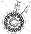
Fig. 3] Fig. 3 is an explanatory view of an example of the configuration of the washing unit of the seaming device according to the embodiment of the present invention when seen from the lower surface of a seaming turret. - [
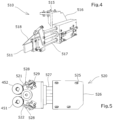
Fig. 4] Fig. 4 is a perspective view showing a chuck washing member inFig. 3 in an enlarged fashion. - [
Fig. 5] Fig. 5 is a schematic plan view showing a seaming roll washing member inFig. 3 in an enlarged fashion. - [
Fig. 6] Fig. 6 is a perspective view showing the seaming roll washing member inFig. 3 in an enlarged fashion. - Hereinafter, the present invention will be described in detail.
- As shown in
Fig. 1 , aseaming device 100 according to an embodiment of the present invention includes: aseaming turret 101 that performs the seaming process of a can C and a lid F; a carrying-inconveyor 102 that supplies a can C before seaming to theseaming turret 101 in a non-rotated state; alid supply device 104 that supplies a lid F and includes alid separation unit 210 and alid conveyance turret 250; adischarge turret 107 that carries out a can CM after seaming from theseaming turret 101; and a carrying-outconveyor 108 that carries out a can CM from thedischarge turret 107 to an outside. - Each of the
seaming turret 101, thedischarge turret 107, and thelid conveyance turret 250 has pockets P that separately accommodate and convey cans C and CM and a lid F on their outer peripheral parts, and the carrying-inconveyor 102 hasattachments 103 that separately engage and convey a can C. - The rotation speeds of the
seaming turret 101, thedischarge turret 107, and the lid conveyance turret 250, the movement speed of theattachments 103 of the carrying-inconveyor 102, and a timing at which the respective pockets P and theattachments 103 are linked to each other are adjustably designed so that cans C and CM and a lid F are smoothly transferred between the respective turrets and the conveyors. - As shown in
Fig. 2 , theseaming turret 101 that performs the seaming process of a can C and a lid F includes: a can mountingunit 350 that mounts a can C and rotates the same; achuck unit 320 that is provided facing thecan mounting unit 350 and has achuck 321 that positions a lid F mounted on a can C and aknockout pad 322 that is fitted to be vertically movable inside thechuck 321 so as to press the lid F mounted on the can C; and aseaming unit 410 havingseaming rolls - The
seaming turret 101 is arranged to be rotatable about thecenter shaft 109 with its central axis X extending in a vertical direction, and is rotationally driven by adriving mechanism 151 of theseaming turret 101. - The
lid separation unit 210, the lid conveyance turret 250, and the carrying-inconveyor 102 are mechanically driven by thedriving mechanism 151 of theseaming turret 101 via a transmission mechanism. - The
chuck unit 320 is arranged to be rotatable about thecenter shaft 109 with its central axis X extending in a vertical direction and face the can mounting unit at an equal angular interval, and anouter surface gear 323 of a rotating shaft that supports thechuck 321 at its lower end engages asun gear 324 supported by thecenter shaft 109. Thechuck unit 320 revolves with the rotation of thecenter shaft 109 and a center column, and thechuck 321 rotates on its axis with the engagement between thesun gear 324 and theouter surface gear 323. - The
chuck 321 is provided to be fixed and rotatable in a vertical direction. As shown on the right side of the central axis X inFig. 2 , the centering of a lid F is performed in such a manner that a can C on which the lid F has been mounted by lifting thecan mounting unit 350 is fitted with the lower end outer peripheral surface of thechuck 321 while being sandwiched between theknockout pad 322 and thecan mounting unit 350. - The seaming
unit 410 performs double seaming with seamingrolls lever 450 so as to rotate, the seaminglever 450 having its central part fixed to the lower end of a revolvingroll swinging shaft 132. - In a double seaming process, a curled portion of a lid F is wrapped into a flange portion of a can C by the seaming
roll 451 in primary seaming, and then crimping and bonding are performed by the fastening of seamingroll 452 to maintain sealing in secondary seaming. - As shown in
Fig. 3 , the seamingdevice 100 of the present invention includes awashing unit 500 that washes thechucks 321 of thechuck units 320 and the seaming rolls 451 and 452 of the seamingunits 410. - The
washing unit 500 has achuck washing member 510 and a seamingroll washing member 520 as washing members having cleaning brushes that are advanceable and retractable along a direction toward the seamingturret 101 from an outside. In the present invention, the "cleaning brushes" indicate cleaning parts that are able to exhibit a brush-like cleaning function, are not necessarily limited to those having a shape with a multiplicity of fibers, wires, or the like, and include those having various shapes that will be described later. - The
chuck washing member 510 has achuck cleaning brush 511 that is inserted between adjacent seaming rolls 451 and 452 and able to contact the peripheral lateral surfaces of thechucks 321. Here, the adjacent seaming rolls 451 and 452 indicate a group of two seamingrolls chuck unit 320. As shown inFig. 4 , thechuck washing member 510 hasarms 517 having thechuck cleaning brush 511 fixed at their tip ends. Thechuck cleaning brush 511 has a flat substantially rectangular parallelepiped shape that extends in its advancing and retracting direction and its vertical direction and is compressed in a circumferential direction, and has a length with which thecleaning brush 511 is insertable between adjacent seaming rolls 451 and 452 and its tip end reaches thechucks 321 of thechuck units 320. Thearms 517 are provided to be expandable and contractable along the advancing and retracting direction of the washing member at the lower part of asupport part 516 having its upper part fixed to an in-machine housing serving as a fixation part bybolts 515. On the upper side of thechuck cleaning brush 511 at the tip ends of thearms 517, anozzle 518 that jets a washing agent to a washing portion is provided. - In the
chuck washing member 510, thechuck cleaning brush 511 and thenozzle 518 constitute a movable unit made integrally advanceable and retractable by thearms 517. The movable unit of thechuck washing member 510 is advanceable and retractable along the radial direction of the central axis X of the seamingturret 101, specifically, along a direction toward between adjacent seaming rolls 451 and 452 from the outside. - The seaming
roll washing member 520 has a drivingroller 529 that is able to press both adjacent seaming rolls 451 and 452 and seaming roll cleaning brushes 521 and 522 that are able to contact the two seamingrolls Fig. 5 , the seamingroll washing member 520 hasarms 527 having roll brushes and the drivingroller 529 such as a rubber roller fixed at their tip ends. As shown inFig. 6 , the drivingroller 529 is provided to rotate about its axis parallel to the rotating axes of seaming rolls 451 and 452 by an electrically or pneumatically drivenmotor 523. At the lower part of asupport part 526 having its upper part fixed to the in-machine housing serving as the fixation part bybolts 525, thearms 527 are provided to be expandable and contractable along the advancing and retracting direction of a movable unit. The seaming roll cleaning brushes 521 and 522 contact the peripheral lateral surfaces of seaming rolls 451 and 452 rotated by the drivingroller 529, have a flat substantially rectangular parallelepiped shape like thechuck cleaning brush 511 of thechuck washing member 510, and are provided in a posture extending in a direction diagonal to the advancing and retracting direction of the movable unit. Further,nozzles 528 that jet the washing agent to a washing portion are provided on the lateral sides of the seaming roll cleaning brushes 521 and 522. - In the seaming
roll washing member 520, the seaming roll cleaning brushes 521 and 522, thenozzles roller 529 constitute the movable unit made integrally advanceable and retractable by thearms 527. The movable unit of the seamingroll washing member 520 is advanceable and retractable along the radial direction of the central axis X of the seamingturret 101, specifically, along a direction toward between adjacent seaming rolls 451 and 452 from the outside. - The
chuck washing member 510 and the seamingroll washing member 520 are, respectively, arranged at adjacent pitch positions according to the revolving pitch of thechuck units 320 by the seamingturret 101. - Examples of the shapes of the
chuck cleaning brush 511 and the seaming roll cleaning brushes 521 and 522 can include a brush shape with a multiplicity of fibers, wires, or the like, a solid sheet shape, a sponge shape, or the like. - Examples of the materials of the
chuck cleaning brush 511 and the seaming roll cleaning brushes 521 and 522 can include nylon, polypropylene, palm, coco, hemp, rubber, nonwoven cloth, or the like. - Further, the washing agent filled in the
nozzles - The seaming
device 100 of the present invention has the washing control mechanism of causing, at the selection of a washing mode, the movable unit including thechuck cleaning brush 511 of thechuck washing member 510 and the movable unit including the seaming roll cleaning brushes 521 and 522 of the seamingroll washing member 520 to automatically move toward the seamingturret 101 along the advancing and retracting direction of the washing members when thechucks 321 provided in thechuck units 320 are rotatable on their axes while the revolution of thechuck unit 320 by the seamingturret 101 is stopped. - In the washing control mechanism, a washing operation is controlled to be performed for every prescribed interval of the revolution of the
chuck units 320 by the seamingturret 101. Specifically, the washing operation is controlled to be performed for every pitch of thechucks 321 by a servo motor that causes thechucks 321 to rotate on their axes. - The present embodiment describes an example in which the seaming
device 100 has the two washing member (thechuck washing member 510 and the seaming roll washing member 520). However, the present invention does not exclude an example in which the seamingdevice 100 has only one of thechuck washing member 510 and the seamingroll washing member 520. Further, a configuration in which seamingdevice 100 has a plurality of thechuck washing members 510, a configuration in which seamingdevice 100 has a plurality of the seamingroll washing members 520, or the like may be employed. Moreover, a configuration in which the seamingdevice 100 has a plurality of thechuck washing members 510 and a plurality of the seamingroll washing members 520 may be employed. - The basic operation of the seaming
device 100 thus configured will be described. - A can C to which a lid F has been seamed is conveyed while engaging each of the
attachments 103 of the carrying-inconveyor 102 and directed to the seamingturret 101 rotated by thedriving mechanism 151 of the seamingturret 101. - On the other hand, the lid F is cut out one by one from the
lid separation unit 210, transferred to each of the pockets P of thelid conveyance turret 250, and directed to the seamingturret 101 by the rotation of the lid conveyance turret 250 (seeFig. 1 ). - The speeds and timings of the carrying-in
conveyor 102 and thelid conveyance turret 250 are adjusted according to the speed and timing of the seamingturret 101 so that the centers of the can C and the lid F are aligned with each other at a merging point G. When thecan mounting unit 350 of which the rotation is controlled via appropriate gears, a cam mechanism, or the like by thedriving mechanism 151 to which power has been applied from a driving source not shown is lifted at the merging point G, the lid F is mounted on the can C mounted on theplate 360. - After that, the
can mounting unit 350 is further lifted, theknockout pad 322 inside thechuck 321 presses the lid F, and thechuck 321 of which the rotation is controlled via appropriate gears, a cam mechanism, or the like by thedriving mechanism 151 is fitted into the lid F to perform the centering of the lid F. The can C on which the lid F has been mounted is sandwiched between theplate 360, thechuck 321, and theknockout pad 322 at a constant axial load necessary for seaming. - Then, the seaming
turret 101 further rotates, and theplate 360 and thechuck 321 accelerate up to their rotation numbers necessary for seaming before the sandwiched lid F and the can C reach a seaming interval E shown inFig. 1 . - While passing through the seaming interval E, the seaming
lever 450 fixed to the lower end of theroll swinging shaft 132 of the seamingunit 410 is swung. Thus, two seamingrolls chuck 321 to perform double seaming. - The can CM having completed the seaming is transferred from the seaming
turret 101 to thedischarge turret 107 and then transferred from thedischarge turret 107 to the carrying-outconveyor 108 to be carried out to a next process such as inspection and packaging. - In the
washing unit 500 of the present invention, the revolution of thechuck units 320 by thedriving mechanism 151 of the seamingturret 101 is stopped for every prescribed interval (for every pitch) on the basis of the movement of the servo motor that causes thechucks 321 to rotate on their axes at the selection of a washing mode. At this time, thechuck 321 of onechuck unit 320 is stopped at a first fixed washing position closest to thechuck washing member 510, and the seaming rolls 451 and 452 of the seamingunit 410 corresponding to theadjacent chuck unit 320 are stopped at a second fixed washing position closest to the seamingroll washing member 520. - In the
chuck unit 320 having stopped its revolution at the first fixed washing position, thearms 517 of thechuck washing member 510 extend, and the movable unit including thechuck cleaning brush 511 moves in a direction toward the seamingturret 101 from the outside. Thus, thechuck cleaning brush 511 is inserted between the two seamingrolls chuck unit 320, and its tip end is pressed against the peripheral lateral surface of thechuck 321. After that, thechuck 321 is caused to rotate on its axis by the driving mechanism of 151 of thechuck unit 320 without accompanying revolution while the washing agent is jetted from thenozzle 518, and the peripheral lateral surface of thechuck 321 is washed by being rubbed against thechuck cleaning brush 511. - In the seaming
unit 410 having stopped its revolution at the second fixed washing position, thearms 527 of the seamingroll washing member 520 extend, and the movable unit including the seaming roll cleaning brushes 521 and 522 moves in a direction toward the seamingturret 101 from the outside. Then, the drivingroller 529 simultaneously presses the seaming rolls 451 and 452, and the tip ends of the seaming roll cleaning brushes 521 and 522 are pressed against the respective peripheral lateral surfaces of the seaming rolls 451 and 452. After that, the seaming rolls 451 and 452 are driven by the rotation of the drivingroller 529 while the washing agent is jetted from thenozzles - When the above two types of washing operations are repeatedly performed over one revolution of the seaming
turret 101, thechucks 321 relating to thechuck units 320 and the seaming rolls 451 and 452 of the seamingunit 410 are sequentially washed by thechuck washing member 510 and the seamingroll washing member 520, respectively. -
- 100
- Seaming device
- 101
- Seaming turret
- 102
- Carrying-in conveyor
- 103
- Attachment
- 104
- Lid supply device
- 107
- Discharge turret
- 108
- Carrying-out conveyor
- 109
- Center shaft
- 132
- Roll swinging shaft
- 151
- Driving mechanism
- 210
- Lid separation unit
- 250
- Lid conveyance turret
- 320
- Chuck unit
- 321
- Chuck
- 322
- Knockout pad
- 323
- Outer surface gear
- 324
- Sun gear
- 350
- Can mounting unit
- 360
- Plate
- 410
- Seaming unit
- 450
- Seaming lever
- 451
- Seaming roll (primary seaming)
- 452
- Seaming roll (secondary seaming)
- 500
- Washing unit
- 510
- Chuck washing member
- 511
- Chuck cleaning brush
- 515
- Bolt
- 516
- Support part
- 517
- Arm
- 518
- Nozzle
- 520
- Seaming roll washing member
- 521
- Seaming roll cleaning brush
- 522
- Seaming roll cleaning brush
- 523
- Motor
- 525
- Bolt
- 526
- Support part
- 527
- Arm
- 528
- Nozzle
- 529
- Driving roller
- C
- Can (before seaming)
- F
- Lid
- CM
- Can (after seaming)
- P
- E
- Seaming interval
- X
- Central axis
Claims (6)
- A seaming device (100) comprising:a seaming turret (101) including a plurality of chuck units (320) and a plurality of seaming units (410); anda washing unit (500) configured to wash seaming rolls (451, 452) of the seaming units, whereinthe washing unit includes a washing member (510, 520) having a cleaning brush (511, 521, 522) that is advanceable and retractable along a direction toward the seaming turret from outside when a washing mode is selected, the seaming device being characterized in thatthe washing unit is further configured to wash chucks (521) of the chuck units, andthe seaming device further includes a washing control mechanism that performs a washing operation to cause the cleaning brush to move toward the seaming turret, with the chucks that are provided in the chuck units being rotatable on axes thereof while stopping revolution of the chuck units by the seaming turret.
- The seaming device according to claim 1, wherein
the washing member is provided in plurality. - The seaming device according to claim 1 or 2, whereinthe washing member is a chuck washing member (510) having a chuck cleaning brush (511) that is inserted between adjacent seaming rolls(451, 452) andable to contact the chucks a (321) and/or a seaming roll washing member (520) having a driving roller (529)that is able to press both adjacent seaming rolls and a seaming roll cleaning brush (521, 522) that is able to contact the seaming rolls.
- The seaming device according to any of claims 1 to 3, wherein
the washing control mechanism performs control so that a washing operation is performed for every prescribed interval of revolution of the chuck units by the seaming turret. - The seaming device according to claim 4, wherein
the washing control mechanism performs control so that a washing operation is performed for every pitch of the chucks. - The seaming device according to any of claims 1 to 5, wherein
the washing control mechanism causes the cleaning brush to automatically move toward the seaming turret when the chucks provided in the chuck units are rotatable on axes thereof while revolution of the chuck units by the seaming turret is stopped.
Applications Claiming Priority (6)
| Application Number | Priority Date | Filing Date | Title |
|---|---|---|---|
| JP2020044200A JP7621063B2 (en) | 2020-03-13 | 2020-03-13 | Sealing device |
| JP2020044199A JP7570180B2 (en) | 2020-03-13 | 2020-03-13 | Container member supply device |
| JP2020044198A JP7510263B2 (en) | 2020-03-13 | 2020-03-13 | Sealing device |
| JP2020044202A JP7457542B2 (en) | 2020-03-13 | 2020-03-13 | Sealing device |
| JP2020044201A JP7458213B2 (en) | 2020-03-13 | 2020-03-13 | Sealing device |
| PCT/JP2020/044476 WO2021181765A1 (en) | 2020-03-13 | 2020-11-30 | Seaming device |
Publications (3)
| Publication Number | Publication Date |
|---|---|
| EP4119256A1 EP4119256A1 (en) | 2023-01-18 |
| EP4119256A4 EP4119256A4 (en) | 2024-05-01 |
| EP4119256B1 true EP4119256B1 (en) | 2025-03-19 |
Family
ID=90236217
Family Applications (1)
| Application Number | Title | Priority Date | Filing Date |
|---|---|---|---|
| EP20924759.2A Active EP4119256B1 (en) | 2020-03-13 | 2020-11-30 | Seaming device |
Country Status (4)
| Country | Link |
|---|---|
| EP (1) | EP4119256B1 (en) |
| CN (1) | CN115279510B (en) |
| TW (1) | TWI856231B (en) |
| WO (1) | WO2021181765A1 (en) |
Families Citing this family (1)
| Publication number | Priority date | Publication date | Assignee | Title |
|---|---|---|---|---|
| CN118268290B (en) * | 2024-05-20 | 2024-08-13 | 济南威成汽车零部件有限公司 | Gear ring continuous cleaning packaging line |
Family Cites Families (9)
| Publication number | Priority date | Publication date | Assignee | Title |
|---|---|---|---|---|
| JPS62244537A (en) | 1986-04-17 | 1987-10-24 | Toyo Seikan Kaisha Ltd | Method and device for seaming can |
| DK170987B1 (en) * | 1993-04-06 | 1996-04-15 | Lydteknisk Inst | Method for checking the closure of a can or container, and sealing machine for carrying out the method |
| US5564877A (en) * | 1995-01-10 | 1996-10-15 | Reynolds Metals Company | Liner machine for applying sealing compound to can ends |
| JP4044638B2 (en) * | 1997-02-03 | 2008-02-06 | 東洋製罐株式会社 | Cima cleaning method and apparatus |
| JP3967907B2 (en) * | 2001-10-31 | 2007-08-29 | 東洋製罐株式会社 | Leakage lubricant recovery device for lid clamp |
| JP2003170996A (en) * | 2001-12-07 | 2003-06-17 | Toyo Food Equipment Co Ltd | Oiling apparatus for seaming roll of can rolling machine |
| JP2003205334A (en) * | 2002-01-11 | 2003-07-22 | Toyo Food Equipment Co Ltd | Cleaning device in leaked oil collecting apparatus for seaming spindle of can seamer |
| JP6877875B2 (en) * | 2015-06-12 | 2021-05-26 | 東洋製罐株式会社 | Winding device |
| ES2608916B2 (en) * | 2017-03-01 | 2017-12-12 | Fernando FUENTES HERNÁNDEZ | USEFUL FOR CLEANING WHEELS OF CLOSING MACHINES OF CONTAINERS OR CANS |
-
2020
- 2020-11-30 CN CN202080098283.1A patent/CN115279510B/en active Active
- 2020-11-30 EP EP20924759.2A patent/EP4119256B1/en active Active
- 2020-11-30 WO PCT/JP2020/044476 patent/WO2021181765A1/en not_active Ceased
-
2021
- 2021-01-13 TW TW110101195A patent/TWI856231B/en active
Also Published As
| Publication number | Publication date |
|---|---|
| WO2021181765A1 (en) | 2021-09-16 |
| TWI856231B (en) | 2024-09-21 |
| TW202200288A (en) | 2022-01-01 |
| EP4119256A1 (en) | 2023-01-18 |
| EP4119256A4 (en) | 2024-05-01 |
| CN115279510B (en) | 2025-06-03 |
| CN115279510A (en) | 2022-11-01 |
Similar Documents
| Publication | Publication Date | Title |
|---|---|---|
| US4325775A (en) | Delabeler | |
| EP2821149A1 (en) | Apparatus and system for the external cleaning of containers for loose substances | |
| KR20090089255A (en) | Goods handling equipment | |
| EP4086181A1 (en) | Bag processing machine | |
| US20160167895A1 (en) | Container processing machine and method for operating a container processing machine | |
| CN210847563U (en) | Bottle belt cleaning device | |
| CN210138920U (en) | Bottle belt cleaning device | |
| EP4119256A1 (en) | Seaming device | |
| US5258073A (en) | Method for preventing deposition on portions of workpieces during continuous spray coating | |
| CN213431835U (en) | Be used for chlorine dioxide sanitizer packing shell degassing unit | |
| KR101101557B1 (en) | Bottle | |
| KR102360301B1 (en) | charging system | |
| JP7457542B2 (en) | Sealing device | |
| JP2580329B2 (en) | Filling processing equipment | |
| EP1120171B1 (en) | A machine for washing containers | |
| CN219326591U (en) | Integrated control filling line | |
| KR102356758B1 (en) | charging system | |
| US2199459A (en) | Apparatus for cleaning bottles | |
| JP2021023915A (en) | Container cleaning device | |
| US20050155635A1 (en) | Apparatus for washing the interior of containers made of plastic material | |
| CN216441314U (en) | Bottle washing machine for cleaning outer wall of bottle | |
| CN100589888C (en) | Method for processing a frame and processing device for a frame to which the method is applied | |
| CN218706339U (en) | Bottle arrangement transmission device | |
| CN210102231U (en) | Be used for ointment filling to seal tail and press batch number device | |
| JP2005095724A (en) | Box processing method and box processing device using it |
Legal Events
| Date | Code | Title | Description |
|---|---|---|---|
| STAA | Information on the status of an ep patent application or granted ep patent |
Free format text: STATUS: THE INTERNATIONAL PUBLICATION HAS BEEN MADE |
|
| PUAI | Public reference made under article 153(3) epc to a published international application that has entered the european phase |
Free format text: ORIGINAL CODE: 0009012 |
|
| STAA | Information on the status of an ep patent application or granted ep patent |
Free format text: STATUS: REQUEST FOR EXAMINATION WAS MADE |
|
| 17P | Request for examination filed |
Effective date: 20221011 |
|
| AK | Designated contracting states |
Kind code of ref document: A1 Designated state(s): AL AT BE BG CH CY CZ DE DK EE ES FI FR GB GR HR HU IE IS IT LI LT LU LV MC MK MT NL NO PL PT RO RS SE SI SK SM TR |
|
| DAV | Request for validation of the european patent (deleted) | ||
| DAX | Request for extension of the european patent (deleted) | ||
| REG | Reference to a national code |
Ref country code: DE Ref legal event code: R079 Free format text: PREVIOUS MAIN CLASS: B21D0051300000 Ipc: B21D0051320000 Ref country code: DE Ref legal event code: R079 Ref document number: 602020048151 Country of ref document: DE Free format text: PREVIOUS MAIN CLASS: B21D0051300000 Ipc: B21D0051320000 |
|
| A4 | Supplementary search report drawn up and despatched |
Effective date: 20240328 |
|
| RIC1 | Information provided on ipc code assigned before grant |
Ipc: B65B 7/28 20060101ALN20240322BHEP Ipc: B08B 1/12 20240101ALI20240322BHEP Ipc: B21D 51/26 20060101ALI20240322BHEP Ipc: B21D 51/32 20060101AFI20240322BHEP |
|
| REG | Reference to a national code |
Ref country code: DE Ref legal event code: R079 Free format text: PREVIOUS MAIN CLASS: B21D0051320000 Ipc: B21D0051260000 Ref country code: DE Ref legal event code: R079 Ref document number: 602020048151 Country of ref document: DE Free format text: PREVIOUS MAIN CLASS: B21D0051320000 Ipc: B21D0051260000 |
|
| GRAP | Despatch of communication of intention to grant a patent |
Free format text: ORIGINAL CODE: EPIDOSNIGR1 |
|
| STAA | Information on the status of an ep patent application or granted ep patent |
Free format text: STATUS: GRANT OF PATENT IS INTENDED |
|
| RIC1 | Information provided on ipc code assigned before grant |
Ipc: B21D 51/32 20060101ALN20240924BHEP Ipc: B21D 43/16 20060101ALN20240924BHEP Ipc: B65B 7/28 20060101ALN20240924BHEP Ipc: B08B 3/02 20060101ALI20240924BHEP Ipc: B21D 43/06 20060101ALI20240924BHEP Ipc: B08B 1/12 20240101ALI20240924BHEP Ipc: B21D 51/26 20060101AFI20240924BHEP |
|
| INTG | Intention to grant announced |
Effective date: 20241008 |
|
| GRAS | Grant fee paid |
Free format text: ORIGINAL CODE: EPIDOSNIGR3 |
|
| GRAA | (expected) grant |
Free format text: ORIGINAL CODE: 0009210 |
|
| STAA | Information on the status of an ep patent application or granted ep patent |
Free format text: STATUS: THE PATENT HAS BEEN GRANTED |
|
| AK | Designated contracting states |
Kind code of ref document: B1 Designated state(s): AL AT BE BG CH CY CZ DE DK EE ES FI FR GB GR HR HU IE IS IT LI LT LU LV MC MK MT NL NO PL PT RO RS SE SI SK SM TR |
|
| REG | Reference to a national code |
Ref country code: GB Ref legal event code: FG4D |
|
| REG | Reference to a national code |
Ref country code: CH Ref legal event code: EP |
|
| REG | Reference to a national code |
Ref country code: IE Ref legal event code: FG4D |
|
| REG | Reference to a national code |
Ref country code: DE Ref legal event code: R096 Ref document number: 602020048151 Country of ref document: DE |
|
| P01 | Opt-out of the competence of the unified patent court (upc) registered |
Free format text: CASE NUMBER: APP_13259/2025 Effective date: 20250318 |
|
| PG25 | Lapsed in a contracting state [announced via postgrant information from national office to epo] |
Ref country code: RS Free format text: LAPSE BECAUSE OF FAILURE TO SUBMIT A TRANSLATION OF THE DESCRIPTION OR TO PAY THE FEE WITHIN THE PRESCRIBED TIME-LIMIT Effective date: 20250619 |
|
| PG25 | Lapsed in a contracting state [announced via postgrant information from national office to epo] |
Ref country code: FI Free format text: LAPSE BECAUSE OF FAILURE TO SUBMIT A TRANSLATION OF THE DESCRIPTION OR TO PAY THE FEE WITHIN THE PRESCRIBED TIME-LIMIT Effective date: 20250319 |
|
| REG | Reference to a national code |
Ref country code: LT Ref legal event code: MG9D |
|
| PG25 | Lapsed in a contracting state [announced via postgrant information from national office to epo] |
Ref country code: NO Free format text: LAPSE BECAUSE OF FAILURE TO SUBMIT A TRANSLATION OF THE DESCRIPTION OR TO PAY THE FEE WITHIN THE PRESCRIBED TIME-LIMIT Effective date: 20250619 |
|
| PG25 | Lapsed in a contracting state [announced via postgrant information from national office to epo] |
Ref country code: HR Free format text: LAPSE BECAUSE OF FAILURE TO SUBMIT A TRANSLATION OF THE DESCRIPTION OR TO PAY THE FEE WITHIN THE PRESCRIBED TIME-LIMIT Effective date: 20250319 |
|
| PG25 | Lapsed in a contracting state [announced via postgrant information from national office to epo] |
Ref country code: LV Free format text: LAPSE BECAUSE OF FAILURE TO SUBMIT A TRANSLATION OF THE DESCRIPTION OR TO PAY THE FEE WITHIN THE PRESCRIBED TIME-LIMIT Effective date: 20250319 |
|
| PG25 | Lapsed in a contracting state [announced via postgrant information from national office to epo] |
Ref country code: GR Free format text: LAPSE BECAUSE OF FAILURE TO SUBMIT A TRANSLATION OF THE DESCRIPTION OR TO PAY THE FEE WITHIN THE PRESCRIBED TIME-LIMIT Effective date: 20250620 Ref country code: BG Free format text: LAPSE BECAUSE OF FAILURE TO SUBMIT A TRANSLATION OF THE DESCRIPTION OR TO PAY THE FEE WITHIN THE PRESCRIBED TIME-LIMIT Effective date: 20250319 |
|
| REG | Reference to a national code |
Ref country code: NL Ref legal event code: MP Effective date: 20250319 |
|
| REG | Reference to a national code |
Ref country code: AT Ref legal event code: MK05 Ref document number: 1776563 Country of ref document: AT Kind code of ref document: T Effective date: 20250319 |
|
| PG25 | Lapsed in a contracting state [announced via postgrant information from national office to epo] |
Ref country code: NL Free format text: LAPSE BECAUSE OF FAILURE TO SUBMIT A TRANSLATION OF THE DESCRIPTION OR TO PAY THE FEE WITHIN THE PRESCRIBED TIME-LIMIT Effective date: 20250319 |
|
| PG25 | Lapsed in a contracting state [announced via postgrant information from national office to epo] |
Ref country code: SE Free format text: LAPSE BECAUSE OF FAILURE TO SUBMIT A TRANSLATION OF THE DESCRIPTION OR TO PAY THE FEE WITHIN THE PRESCRIBED TIME-LIMIT Effective date: 20250319 |
|
| PG25 | Lapsed in a contracting state [announced via postgrant information from national office to epo] |
Ref country code: SM Free format text: LAPSE BECAUSE OF FAILURE TO SUBMIT A TRANSLATION OF THE DESCRIPTION OR TO PAY THE FEE WITHIN THE PRESCRIBED TIME-LIMIT Effective date: 20250319 |
|
| PG25 | Lapsed in a contracting state [announced via postgrant information from national office to epo] |
Ref country code: ES Free format text: LAPSE BECAUSE OF FAILURE TO SUBMIT A TRANSLATION OF THE DESCRIPTION OR TO PAY THE FEE WITHIN THE PRESCRIBED TIME-LIMIT Effective date: 20250319 Ref country code: PT Free format text: LAPSE BECAUSE OF FAILURE TO SUBMIT A TRANSLATION OF THE DESCRIPTION OR TO PAY THE FEE WITHIN THE PRESCRIBED TIME-LIMIT Effective date: 20250721 |
|
| PG25 | Lapsed in a contracting state [announced via postgrant information from national office to epo] |
Ref country code: IT Free format text: LAPSE BECAUSE OF FAILURE TO SUBMIT A TRANSLATION OF THE DESCRIPTION OR TO PAY THE FEE WITHIN THE PRESCRIBED TIME-LIMIT Effective date: 20250319 Ref country code: PL Free format text: LAPSE BECAUSE OF FAILURE TO SUBMIT A TRANSLATION OF THE DESCRIPTION OR TO PAY THE FEE WITHIN THE PRESCRIBED TIME-LIMIT Effective date: 20250319 |
|
| PG25 | Lapsed in a contracting state [announced via postgrant information from national office to epo] |
Ref country code: AT Free format text: LAPSE BECAUSE OF FAILURE TO SUBMIT A TRANSLATION OF THE DESCRIPTION OR TO PAY THE FEE WITHIN THE PRESCRIBED TIME-LIMIT Effective date: 20250319 |
|
| PG25 | Lapsed in a contracting state [announced via postgrant information from national office to epo] |
Ref country code: CZ Free format text: LAPSE BECAUSE OF FAILURE TO SUBMIT A TRANSLATION OF THE DESCRIPTION OR TO PAY THE FEE WITHIN THE PRESCRIBED TIME-LIMIT Effective date: 20250319 Ref country code: EE Free format text: LAPSE BECAUSE OF FAILURE TO SUBMIT A TRANSLATION OF THE DESCRIPTION OR TO PAY THE FEE WITHIN THE PRESCRIBED TIME-LIMIT Effective date: 20250319 |
|
| PG25 | Lapsed in a contracting state [announced via postgrant information from national office to epo] |
Ref country code: RO Free format text: LAPSE BECAUSE OF FAILURE TO SUBMIT A TRANSLATION OF THE DESCRIPTION OR TO PAY THE FEE WITHIN THE PRESCRIBED TIME-LIMIT Effective date: 20250319 |
|
| PG25 | Lapsed in a contracting state [announced via postgrant information from national office to epo] |
Ref country code: SK Free format text: LAPSE BECAUSE OF FAILURE TO SUBMIT A TRANSLATION OF THE DESCRIPTION OR TO PAY THE FEE WITHIN THE PRESCRIBED TIME-LIMIT Effective date: 20250319 |
|
| PG25 | Lapsed in a contracting state [announced via postgrant information from national office to epo] |
Ref country code: IS Free format text: LAPSE BECAUSE OF FAILURE TO SUBMIT A TRANSLATION OF THE DESCRIPTION OR TO PAY THE FEE WITHIN THE PRESCRIBED TIME-LIMIT Effective date: 20250719 |
|
| REG | Reference to a national code |
Ref country code: CH Ref legal event code: U11 Free format text: ST27 STATUS EVENT CODE: U-0-0-U10-U11 (AS PROVIDED BY THE NATIONAL OFFICE) Effective date: 20251201 |
|
| REG | Reference to a national code |
Ref country code: DE Ref legal event code: R097 Ref document number: 602020048151 Country of ref document: DE |
|
| PGFP | Annual fee paid to national office [announced via postgrant information from national office to epo] |
Ref country code: DE Payment date: 20251015 Year of fee payment: 6 |
|
| PG25 | Lapsed in a contracting state [announced via postgrant information from national office to epo] |
Ref country code: DK Free format text: LAPSE BECAUSE OF FAILURE TO SUBMIT A TRANSLATION OF THE DESCRIPTION OR TO PAY THE FEE WITHIN THE PRESCRIBED TIME-LIMIT Effective date: 20250319 |
|
| PGFP | Annual fee paid to national office [announced via postgrant information from national office to epo] |
Ref country code: CH Payment date: 20251201 Year of fee payment: 6 |
|
| PLBE | No opposition filed within time limit |
Free format text: ORIGINAL CODE: 0009261 |
|
| STAA | Information on the status of an ep patent application or granted ep patent |
Free format text: STATUS: NO OPPOSITION FILED WITHIN TIME LIMIT |
|
| REG | Reference to a national code |
Ref country code: CH Ref legal event code: L10 Free format text: ST27 STATUS EVENT CODE: U-0-0-L10-L00 (AS PROVIDED BY THE NATIONAL OFFICE) Effective date: 20260128 |
|
| 26N | No opposition filed |
Effective date: 20251222 |