EP4119014A1 - Vorrichtung zum heizen und abgeben von wasser - Google Patents
Vorrichtung zum heizen und abgeben von wasser Download PDFInfo
- Publication number
- EP4119014A1 EP4119014A1 EP22184784.1A EP22184784A EP4119014A1 EP 4119014 A1 EP4119014 A1 EP 4119014A1 EP 22184784 A EP22184784 A EP 22184784A EP 4119014 A1 EP4119014 A1 EP 4119014A1
- Authority
- EP
- European Patent Office
- Prior art keywords
- water
- container
- level
- dispensing
- pressure
- Prior art date
- Legal status (The legal status is an assumption and is not a legal conclusion. Google has not performed a legal analysis and makes no representation as to the accuracy of the status listed.)
- Pending
Links
- XLYOFNOQVPJJNP-UHFFFAOYSA-N water Substances O XLYOFNOQVPJJNP-UHFFFAOYSA-N 0.000 title claims abstract description 235
- 238000010438 heat treatment Methods 0.000 title claims abstract description 90
- 230000001105 regulatory effect Effects 0.000 claims abstract description 19
- 239000007788 liquid Substances 0.000 claims description 27
- 238000009835 boiling Methods 0.000 claims description 17
- 239000012530 fluid Substances 0.000 claims description 13
- 238000000034 method Methods 0.000 claims description 12
- 230000009467 reduction Effects 0.000 claims description 11
- 238000004891 communication Methods 0.000 claims description 3
- 238000001514 detection method Methods 0.000 claims description 3
- 238000011049 filling Methods 0.000 claims description 2
- 238000011068 loading method Methods 0.000 description 7
- 238000002360 preparation method Methods 0.000 description 6
- 230000008901 benefit Effects 0.000 description 5
- 230000000694 effects Effects 0.000 description 5
- 235000013305 food Nutrition 0.000 description 5
- 238000002156 mixing Methods 0.000 description 5
- 235000013361 beverage Nutrition 0.000 description 4
- 238000004519 manufacturing process Methods 0.000 description 4
- 230000004913 activation Effects 0.000 description 3
- 238000010586 diagram Methods 0.000 description 3
- 238000009434 installation Methods 0.000 description 3
- 238000007726 management method Methods 0.000 description 3
- 239000000523 sample Substances 0.000 description 3
- 230000009471 action Effects 0.000 description 2
- 230000015572 biosynthetic process Effects 0.000 description 2
- 239000008236 heating water Substances 0.000 description 2
- 230000006698 induction Effects 0.000 description 2
- 229920006395 saturated elastomer Polymers 0.000 description 2
- 241001122767 Theaceae Species 0.000 description 1
- 238000013459 approach Methods 0.000 description 1
- 235000012206 bottled water Nutrition 0.000 description 1
- 230000001427 coherent effect Effects 0.000 description 1
- 238000009833 condensation Methods 0.000 description 1
- 230000005494 condensation Effects 0.000 description 1
- 239000004020 conductor Substances 0.000 description 1
- 230000001276 controlling effect Effects 0.000 description 1
- 230000001419 dependent effect Effects 0.000 description 1
- 239000006185 dispersion Substances 0.000 description 1
- 239000003651 drinking water Substances 0.000 description 1
- 230000005611 electricity Effects 0.000 description 1
- 238000001704 evaporation Methods 0.000 description 1
- 230000008020 evaporation Effects 0.000 description 1
- 238000001914 filtration Methods 0.000 description 1
- 239000013505 freshwater Substances 0.000 description 1
- 235000012171 hot beverage Nutrition 0.000 description 1
- 238000007654 immersion Methods 0.000 description 1
- 239000012535 impurity Substances 0.000 description 1
- 238000012423 maintenance Methods 0.000 description 1
- 239000000463 material Substances 0.000 description 1
- 235000012054 meals Nutrition 0.000 description 1
- 239000002184 metal Substances 0.000 description 1
- 239000000203 mixture Substances 0.000 description 1
- 235000012149 noodles Nutrition 0.000 description 1
- 230000010355 oscillation Effects 0.000 description 1
- 235000015927 pasta Nutrition 0.000 description 1
- 230000001681 protective effect Effects 0.000 description 1
- 230000004044 response Effects 0.000 description 1
- 238000012358 sourcing Methods 0.000 description 1
- 238000012546 transfer Methods 0.000 description 1
- 235000013311 vegetables Nutrition 0.000 description 1
Images


Classifications
-
- A—HUMAN NECESSITIES
- A47—FURNITURE; DOMESTIC ARTICLES OR APPLIANCES; COFFEE MILLS; SPICE MILLS; SUCTION CLEANERS IN GENERAL
- A47J—KITCHEN EQUIPMENT; COFFEE MILLS; SPICE MILLS; APPARATUS FOR MAKING BEVERAGES
- A47J31/00—Apparatus for making beverages
- A47J31/44—Parts or details or accessories of beverage-making apparatus
- A47J31/54—Water boiling vessels in beverage making machines
- A47J31/56—Water boiling vessels in beverage making machines having water-level controls; having temperature controls
-
- F—MECHANICAL ENGINEERING; LIGHTING; HEATING; WEAPONS; BLASTING
- F24—HEATING; RANGES; VENTILATING
- F24H—FLUID HEATERS, e.g. WATER OR AIR HEATERS, HAVING HEAT-GENERATING MEANS, e.g. HEAT PUMPS, IN GENERAL
- F24H1/00—Water heaters, e.g. boilers, continuous-flow heaters or water-storage heaters
- F24H1/18—Water-storage heaters
- F24H1/20—Water-storage heaters with immersed heating elements, e.g. electric elements or furnace tubes
-
- F—MECHANICAL ENGINEERING; LIGHTING; HEATING; WEAPONS; BLASTING
- F24—HEATING; RANGES; VENTILATING
- F24H—FLUID HEATERS, e.g. WATER OR AIR HEATERS, HAVING HEAT-GENERATING MEANS, e.g. HEAT PUMPS, IN GENERAL
- F24H15/00—Control of fluid heaters
- F24H15/20—Control of fluid heaters characterised by control inputs
- F24H15/242—Pressure
-
- F—MECHANICAL ENGINEERING; LIGHTING; HEATING; WEAPONS; BLASTING
- F24—HEATING; RANGES; VENTILATING
- F24H—FLUID HEATERS, e.g. WATER OR AIR HEATERS, HAVING HEAT-GENERATING MEANS, e.g. HEAT PUMPS, IN GENERAL
- F24H15/00—Control of fluid heaters
- F24H15/20—Control of fluid heaters characterised by control inputs
- F24H15/246—Water level
-
- F—MECHANICAL ENGINEERING; LIGHTING; HEATING; WEAPONS; BLASTING
- F24—HEATING; RANGES; VENTILATING
- F24H—FLUID HEATERS, e.g. WATER OR AIR HEATERS, HAVING HEAT-GENERATING MEANS, e.g. HEAT PUMPS, IN GENERAL
- F24H15/00—Control of fluid heaters
- F24H15/30—Control of fluid heaters characterised by control outputs; characterised by the components to be controlled
- F24H15/305—Control of valves
- F24H15/31—Control of valves of valves having only one inlet port and one outlet port, e.g. flow rate regulating valves
-
- F—MECHANICAL ENGINEERING; LIGHTING; HEATING; WEAPONS; BLASTING
- F24—HEATING; RANGES; VENTILATING
- F24H—FLUID HEATERS, e.g. WATER OR AIR HEATERS, HAVING HEAT-GENERATING MEANS, e.g. HEAT PUMPS, IN GENERAL
- F24H15/00—Control of fluid heaters
- F24H15/30—Control of fluid heaters characterised by control outputs; characterised by the components to be controlled
- F24H15/305—Control of valves
- F24H15/32—Control of valves of switching valves
-
- F—MECHANICAL ENGINEERING; LIGHTING; HEATING; WEAPONS; BLASTING
- F24—HEATING; RANGES; VENTILATING
- F24H—FLUID HEATERS, e.g. WATER OR AIR HEATERS, HAVING HEAT-GENERATING MEANS, e.g. HEAT PUMPS, IN GENERAL
- F24H9/00—Details
- F24H9/20—Arrangement or mounting of control or safety devices
- F24H9/2007—Arrangement or mounting of control or safety devices for water heaters
- F24H9/2014—Arrangement or mounting of control or safety devices for water heaters using electrical energy supply
- F24H9/2021—Storage heaters
-
- F—MECHANICAL ENGINEERING; LIGHTING; HEATING; WEAPONS; BLASTING
- F24—HEATING; RANGES; VENTILATING
- F24D—DOMESTIC- OR SPACE-HEATING SYSTEMS, e.g. CENTRAL HEATING SYSTEMS; DOMESTIC HOT-WATER SUPPLY SYSTEMS; ELEMENTS OR COMPONENTS THEREFOR
- F24D2220/00—Components of central heating installations excluding heat sources
- F24D2220/04—Sensors
- F24D2220/046—Pressure sensors
-
- F—MECHANICAL ENGINEERING; LIGHTING; HEATING; WEAPONS; BLASTING
- F24—HEATING; RANGES; VENTILATING
- F24D—DOMESTIC- OR SPACE-HEATING SYSTEMS, e.g. CENTRAL HEATING SYSTEMS; DOMESTIC HOT-WATER SUPPLY SYSTEMS; ELEMENTS OR COMPONENTS THEREFOR
- F24D2220/00—Components of central heating installations excluding heat sources
- F24D2220/04—Sensors
- F24D2220/048—Level sensors, e.g. water level sensors
-
- F—MECHANICAL ENGINEERING; LIGHTING; HEATING; WEAPONS; BLASTING
- F24—HEATING; RANGES; VENTILATING
- F24D—DOMESTIC- OR SPACE-HEATING SYSTEMS, e.g. CENTRAL HEATING SYSTEMS; DOMESTIC HOT-WATER SUPPLY SYSTEMS; ELEMENTS OR COMPONENTS THEREFOR
- F24D2220/00—Components of central heating installations excluding heat sources
- F24D2220/08—Storage tanks
Definitions
- the present invention relates to the sector of apparatus for heating and intermittent dispensing of water intended for human consumption.
- the invention is preferably applicable, though not exclusively, in the sector of boiler systems, of systems for the preparation of beverages, of systems for dispensing of potable water, of systems for preparation of foods or countertop sink and/or lower sink systems.
- water intended for human consumption any water, treated or not, intended for potable use, culinary use or for the preparation of foods or beverages, regardless of the origin and of the type of use, such as for example domestic or industrial.
- apparatuses for heating and intermittent dispensing of water intended for human consumption at a desired dispensing temperature can use pressure equipment.
- pressure equipment equipment subject to a relative pressure of greater than 0.05 MPa; the relative pressure refers to normal atmospheric pressure (0.1013 MPa).
- the pipes, hydraulic valves and the receptacles are generally subjected to specific standards that discipline one or more steps of the life cycle. For example, in Europe the pressure equipment directive, or PED, from the acronym of Pressure Equipment Directive, is applied.
- the apparatuses of the prior art have drawbacks whether they operate at atmospheric pressure, or pressure of the outside environment, or at a different pressure.
- the apparatus operating at atmospheric pressure comprise a receptacle open to the outside environment, so as to maintain the water at atmospheric pressure.
- This configuration reduces the system complications but imposes a dispensing temperature that, if close to boiling, depends on the altitude of installation of the apparatus and is in actual terms lower than 373 K.
- the dispensing temperature will be close to 373 K at sea level and about 370 K at an altitude of about 1000 metres.
- the preparation requires water at a temperature very close to 373 K, sometimes termed boiling or nearly boiling water.
- a pump is generally used to increase the flow of water dispensed; the pump is necessary in a case where the dispensing point is at a higher level than the water in the liquid state in the receptacle.
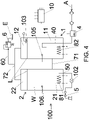
- an apparatus operating at atmospheric pressure is shown by way of example in figure 2 .
- the opening towards the surrounding environment is visible high on the left of the receptacle; it is good practice to include a filtering system at the opening to prevent any impurities from entering the apparatus, even when not in use or in any case switched off.
- the operating temperature can be appropriately stabilised but, as it increases, the structural characteristics of pressure equipment are becoming progressively more stringent.
- the safety coefficients, for good measure, amplify this effect.
- the pressure internally of the receptacle increases significantly during the heating of the water; for example from a pressure of 0.5 Mpa in inlet it can pass beyond 0.9 MPa. All the hydraulic components must be appropriately dimensioned and certified and can wear out quickly as they are subject to significant pressure variations.
- all the hydraulic components are subjected to continuous oscillations of more than 0.5 MPa.
- the inlet of the outlet conduit is located in the area above the receptacle to limit the formation of areas of steam.
- FIG. 1 An example of an apparatus that operates at a different pressure to atmospheric pressure is given by way of example in figure 1 , in which the receptacle can be seen to be connected to a water supply system and to a dispensing conduit provided with a manual valve.
- the reading of a temperature sensor in the example arranged centrally, determines the switching on and off of the resistor on the bottom of the receptacle on the basis of the operating logic and/or of the dispensing temperature set.
- a safety device can be observed, which can interrupt the electrical connection to the resistor and an overpressure valve, for safety, which prevents the operativity of the receptacle at pressures that are not permitted.
- the apparatus of figure 2 requires an inlet valve to interrupt the loading of the receptacle when the water reaches the maximum level, a condition detected by a level detector illustrated at the top on the right of the receptacle.
- US 4480173 A illustrates an apparatus for heating and dispensing water and, necessarily, steam comprising a pressure reducing valve in inlet which can be calibrated, for example, at 0.2 MPa.
- a pressure reducing valve in inlet which can be calibrated, for example, at 0.2 MPa.
- the presence of a like pressure reducing valve does not prevent the pressure increase inside the receptacle which, as illustrated in the foregoing, can exceed 0.9 MPa.
- a first aim of the present invention is to obviate one or more of the drawbacks in the prior art.
- a second aim is to provide an apparatus which enables heating the water to a temperature of close to or higher than the boiling temperature at the pressure of the outside environment, preventing energy loss in the non-pressure apparatus and the drawbacks of pressure apparatus.
- An aim of some embodiments is to limit the influence of the water in inlet on the temperature of the water being dispensed.
- Preferred embodiments intend to limit the pressure variations to which the apparatus is subjected and/or to facilitate the dispensing of the water and/or to facilitate the heat exchange internally of the container so as to best exploit the heating potential.
- a further aim of some embodiments is to improve the response of the apparatus on the basis of the quantity of water dispensed and/or requested.
- the apparatus comprises a container, an inlet conduit internally of the container, an outlet conduit from the inside of the container for dispensing water into the outside environment and heating means of fluids internally of the container.
- the container has an opening which connects the inside towards the outside environment and which is positioned above the level.
- the inlet conduit is configured for connection to a water supply of water intended for human consumption, for example a household water supply, office or production premises system.
- the apparatus further comprises an overpressure valve and one or more control units which control the heating means.
- the overpressure valve allows the flow only in outlet through the opening and when the pressure internally of the container exceeds an intervention value which is greater than the pressure of the outside environment.
- the apparatus advantageously further comprises first means for regulating the flow through the inlet conduit and a level detector which detects the water in the liquid state at the level.
- the outlet conduit has the inlet below the level and the one or more control units also control the first means and are configured in such a way that the first means close the inlet conduit when the level detector detects the water in the liquid state at the level.
- the method comprises steps of providing an apparatus comprising a container, an inlet conduit, an outlet conduit and heating means, injecting water, heating the water and dispensing the water.
- the container has a level and has an opening which connects the inside of the container towards the outside environment and which is positioned above the level.
- the flow is allowed through the opening only with a pressure internally of the container that is greater than an intervention value and greater than the pressure of the external environment pressure.
- the outlet conduit advantageously has its inlet below the level and the apparatus comprises first means for regulating the flow through the inlet conduit and a level detector which detects the water in the liquid state at the level.
- the inlet conduit is closed when the level detector detects water in the liquid state at the level.
- the apparatus and the method according to the invention are conceived and predisposed to dispense heated water in continuous mode, i.e. by means of successive dispensing distanced from one another over time.
- the level determines the maximum quantity of water in the liquid state that is housed internally of the container.
- reference numeral 100 denotes a container of an apparatus for heating and dispensing of water intended for human consumption.
- An embodiment of the apparatus comprises a container (100), an inlet conduit (40) to the inside of the container (100) which is configured for connection to a water supply (A) of water intended for human consumption, an outlet conduit (50) from the inside of the container (100) for dispensing water into the outside environment (E), heating means (8, 81, 82, 83) of fluids internally of the container (100), an overpressure valve (6) and one or more control units (10).
- flow is meant the allowing, interrupting or modulating the flow; these actions are often realised by a valve.
- the dispensing takes place into a beaker, jug or a pan located in the outside environment (E), i.e. at the pressure thereof.
- the container (100) has a level (L) and has an opening (61) which connects the inside of the container (100) towards the outside environment (E) and which is positioned above the level (L).
- the container (100) is predisposed to contain internally thereof fluids at a pressure that is different to the pressure of the environment (E) outside the container (100), at least in an operating condition.
- the container (100) is able to maintain at least an internal pressure that is higher than atmospheric pressure.
- An overpressure valve (6) which allows the flow only in outlet through the opening (61) and when the pressure internally of the container (100) exceeds an intervention value which is greater than the pressure of the outside environment (E).
- the inside of the container (100) is therefore not exposed continuously to atmospheric pressure, differently to what occurs in the prior art example of figure 2 .
- the one or more control units (10) control the heating means (8, 81, 82, 83), so as to heat the water internally of the container (100) on the basis of the desired dispensing temperature.
- the apparatus advantageously also comprises first means (4) for regulating the flow through the inlet conduit (40) and a level detector (103) which detects the water in the liquid state (W) at the level (L), i.e. when the water reaches the level.
- the outlet conduit (50) has the inlet below the level (L) and the one or more control units (10) also control the first means (4) and are configured in such a way that the first means (4) close the inlet conduit (40) when the level detector (103) detects water in the liquid state (W) at the level (L).
- the apparatus of the invention enables heating the water internally of the container (100) without being affected, during the heating and the maintaining of the heated water, by the effects of the value of the pressure of the outside environment (E), as occurs in non-pressure apparatus in the prior art. Further, this apparatus facilitates the dispensing of hot water, which is not preceded by an emission of steam, and prevents, or drastically reduces, loss of water from the container (100) during the heating, as occurs in the pressure apparatus of the prior art.
- the pressure inside increases during the course of the loading up to being substantially equal to the pressure of the water supply (A).
- the quantity of water injected internally of the container (100) is, differently, defined by the level detector (103). With this detail the pressure of the water supply (A) and the pressure inside the container (100) are substantially unlinked.
- the water does not exit from the overpressure valve (6) downstream of the expansion due to the heating thereof.
- the overpressure valve (6) is for example a mechanical valve such as an appropriately calibrated safety valve, which can be calibrated in production and does not require further adjustments.
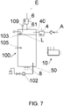
- the overpressure valve (6) is an electrically operated valve that is functionally connected to a sensor (109) of the pressure inside the container, as shown by way of example in figure 7 .
- This realisation enables a rapid variation of the intervention value on the basis of the desired temperature inside the container (100) but is, generally, more expensive and subject to more frequent technical drawbacks.
- the heating means (8, 81, 82, 83) can be, for example, heat exchangers, electrical resistances or induction heaters. Figures from 1 to 6 are represented by the electrical resistances located inside the container (100) while in figure 7 an induction heater with a conductor container (100) can be observed.
- the heating of the water internally of the container (100) to between 374 K and about 383 K does not lead to boiling if the intervention value is a relative pressure of greater than 0.04 MPa.
- the absolute pressure is about 0.14 MPa while at 378 K it is about 0.12 MPa. It is therefore possible to establish the intervention value on the basis of the desired temperature.
- the predetermined temperature for the water inside the container (1) will be equal to or greater than the dispensing temperature, in a case where account is taken of losses in outlet.
- the first means can comprise one or more valves or other switch devices and preferably the first means (4) comprise an electrically operated valve, more preferably a normally-closed electrically operated valve so as to close the inlet conduit (40) towards the inside of the container (100) and prevent loading the container (100) above the level (L) in the case of an absence of electrical energy.
- the apparatus can be kept isolated from the water supply (A) simply by detaching from the energy source. Further, the loading requires connection of the apparatus to the electricity grid.
- the intervention value is preferably a relative pressure, with respect to normal atmospheric pressure, positive and less than or equal to 0.6 MPa, so as to obtain a pressure inside the container (100) that is in any case lower than the pressure in the apparatuses today available on the market which do not operate at atmospheric pressure.
- the intervention value of the overpressure valve (6) is preferably lower than or equal to the pressure of the water supply (A).
- the apparatus will thus be subjected to pressure variations that are very narrow and coherent with those due to the connection with the water supply (A).
- pressure variations typical of pressure apparatus and described in the foregoing.
- the pressure that develops inside the container (100) during the heating cycle is completely independent of the pressure of the water supply (A) and is not influenced thereby in any way. Instead, in the pressure apparatus of the prior art, the pressure during the heating cycle is absolutely dependent on the pressure of the water supply (A) and is always greater than it. It will therefore not be necessary to dimension the container (100), as well as the whole apparatus, for the significant pressures typical of the pressure apparatuses of the prior art, such as the one illustrated in figure 1 .
- the intervention value is preferably a relative pressure, with respect to normal atmospheric pressure, positive and less than or equal to 0.05 MPa.
- the intervention value is greater than 0 Pa, for example 0.04 MPa, i.e. the overpressure valve (6) intervenes in the case of a slight overpressure inside the container (100).
- a like apparatus has the advantages of the invention but is not included in the standards of pressure apparatus, such as for example the above-mentioned PED, with important benefits in constructional, systems and certification terms for use with water intended for human consumption or for food use.
- the pressure that develops inside the container (100) during the heating cycle is completely independent of the pressure of the water supply (A) and is not in any way influenced.
- the apparatus preferably comprises third means (5) for regulating the flow through the outlet conduit (50) and/or a sensor (102) for detecting the flow through the outlet conduit (50) and the one or more control units (10) receive the detections of the sensor (102) for detecting the flow and/or control the third means (5).
- the one or more control units (10) are configured in such a way that, with the dispensing of water, the first means (4) close or limit the flow through the inlet conduit (40) so that the flow through the inlet conduit (40) is lower than the flow through the outlet conduit (50).
- the apparatus thus enables dispensing of water in the liquid state (W) at the desired temperature, even when the water is close to or at 373.15 K, with a flow in outlet useful for the majority of the applications and with a temperature that is almost constant. Further, during the course of the dispensing, the power of the heating means (8, 81, 82, 83) can be better exploited for the water already present inside the container (100).
- the one or more control units (10) are configured in such a way that the first means (4) close the inlet conduit (40) with dispensing of water in such a way as to prevent any mixing effect; the loading of the water internally of the container (100) thus starts at the end of the dispensing, sometimes after a predetermined pause.
- the one or more control units (10) are preferably configured in such a way that the heating means (8, 81, 82, 83) heat at least a part of the water internally of the container (100) to a temperature above the boiling temperature of the water at the pressure of the outside environment (E). This typically means that at least one part of the water inside the container (100) is heated to a temperature of above 373.15 K, so as to enable the dispensing of the boiling water.
- the apparatus of the present description ensures low overpressures inside the container (100) without any need to reduce the pressure of the water in inlet, so that it is preferable that the apparatus does not comprise any inlet pressure reducing valve, differently to US 4480173 A .
- the addition of a like valve increases the costs and constructional and maintenance drawbacks.
- the apparatus of the present description ensures the loading of the container (100) up to the level (L) without any need for dispensing.
- the intervention value is preferably such as to enable the filling of the container (100) with water in the liquid state (W) up to the level (L) without the inside of the container (100) being placed in communication with the outside environment (E), if not via the overpressure valve (6).
- This condition is guaranteed regardless of the position of the level (L) if the intervention value of the overpressure valve (6) is lower than or equal to the pressure of the water supply (A) and, likewise, if lower than or equal to 0.05 MPa.
- the apparatus preferably heats and intermittently dispenses only water intended for human consumption, i.e. it does not comprise outlets for dispensing steam to the user.
- the volume of the inside of the container (100) above the level (L) is preferably predisposed so that the pressure internally of the container (100) is greater than normal atmospheric pressure and/or greater than the pressure of the outside environment (E) after the dispensing of 0.2 dm 3 of heated water.
- the uses of the apparatus are various, in the preparation of numerous beverages and meals, a single dispensing requires at least about 0.2 dm 3 of water.
- the apparatus according to the invention does not exploit, or exploits only very slightly, the pressure of the water supply (A) to accelerate the dispensing of the water.
- the pressure inside the container (100) facilitates the flow in outlet.
- This last pressure is greater than the pressure of the pressure of the outside environment (E).
- the apparatus is produced independently of the place of installation, for example at sea level or in a mountainous area: the pressure internally of the container (100) must indicatively be greater than normal atmospheric pressure.
- the volume of the inside of the container (100) above the level (L) is predisposed, and the apparatus is configured to operate, so that the pressure of the inside of the container (100) is greater than normal atmospheric pressure and/or greater than the pressure of the outside environment (E) after the dispensing of all the water inside the container (100) above the entry to the outlet conduit (50).
- the level (L) is preferably located so that the internal volume of the container (100) below the level (L) is greater than the volume above the level (L) so as to limit the size of the apparatus with respect to the quantity of dispensable water.
- the internal volume of the container (100) is preferably of a cylindrical shape, so as to be of simpler and cheaper manufacture.
- the one or more control units (10) are preferably configured in such a way that the first means (4) close or limit the flow through the inlet conduit (40) so that the water in inlet causes a reduction in the temperature of the water internally of the container (100) which is lower than a predetermined value.
- a controlled inlet flow enables concentrating the thermal potential of the heating means (8, 81, 82, 83) in a variable mass of water, reducing the waiting times for collecting water at the desired temperature, as it is not necessary to wait for the loading and subsequent heating of all the water requested to reach the level (L).
- the overall power of the heating means (8, 81, 82, 83) is often limited for economic reasons, technical reasons and in relation to installation.
- the first means (4) for regulating the flow reduce the flow rate through the inlet conduit (40) so as to maintain the temperature read by one or more temperature sensors (105, 106, 107) above a minimum value; in the case of a plurality of temperature sensors (105, 106, 107) it is preferable to satisfy the same minimum value or respective minimum values.
- the container (100) preferably comprises two or more chambers (1, 2, 3) connected to one another below the level (L), the inlet conduit (40) enters a first chamber (1) and the outlet conduit (50) departs from a second chamber (2).
- the water being dispensed is thus less affected by the different temperature of the water in inlet.
- At least the second chamber (2) and another chamber of the two or more chambers (1, 2, 3) are preferably connected to one another above the level (L) and the heating means (8, 81, 82, 83) comprise first heating means (81) of fluids internally of the second chamber (2) and second heating means (82, 83) of fluids in at least another chamber of the two or more chambers (1, 2, 3).
- connection (72) between two chambers above the level (L) facilitates the exchange between the chambers but with a reduced influence on the temperature of the water being dispensed.
- connection (72) above the level (L) is useful even when there is a formation of steam; this steam can transfer heat to the chamber or chambers connected to the second chamber (2).
- first heating means (81) and second heating means (82, 83) enables optimising the management of the water inside the container (100) on the basis of specific requirements.
- the second chamber (2) can be maintained at temperature, i.e. has a predetermined temperature, that is greater than the other chambers so as to reduce losses and facilitate the heat exchange via the connections (72) above the level (L).
- all of the two or more chambers (1, 2, 3) can operate at the same predetermined temperature so as to avail of a greater quantity of dispensable water at the desired temperature.
- Each of the two or more chambers (1, 2, 3) is preferably associated to a respective means for heating which heats the water internally of the chamber at the predetermined temperature.
- the apparatus can possibly be configured to increase the temperature progressively as the water nears the second chamber (2) and therefore at the outlet conduit (50).
- the one or more control units (10) are preferably configured in such a way that the first heating means (81) and the second heating means (82, 83) heat the water internally of the respective chamber of the two or more chambers (1, 2, 3) up to respective predetermined temperatures that can be different or the same as one another.
- the one or more control units (10) are configured in such a way that the first heating means (81) remain active once the predetermined temperature has been reached, should another chamber of the two or more chambers (1, 2, 3) not have reached the predetermined temperature. This is usually when the chamber or chambers to which the second chamber (2) is connected above the level (L) have not reached the predetermined temperature.
- the power of the first heating means (81) can be advantageously exploited to accelerate the heating of the water in the other chambers of the two or more chambers (1, 2, 3).
- the apparatus preferably comprises a first temperature sensor (105) in the first chamber (1) and the one or more control units (10) are configured in such a way that the first means (4) close the inlet conduit (40) in the case of a reduction in the temperature of the water internally of the first chamber (1) that is greater than a predetermined reduction.
- the control of the flow in inlet can take place on the basis of the fall in temperature in the water in the first chamber (1).
- the one or more control units (10) can also manage the fall in temperature in at least one other chambers of the two or more chambers (1, 2, 3).
- connections (71) between the two or more chambers (1, 2, 3) below the level (L) preferably connect, in series, one chamber with the next from the first chamber (1) to the second chamber (2). In this way the mixing between the water in inlet from the water supply (A) and the water in the second chamber (2) is further limited.
- connection (71) below the level (L) towards the second chamber (2) preferably has an area of the passage section that is greater, often at least double, than the area of the passage section of the inlet conduit (40), still with the aim of reducing the effects of the water in inlet on the dispensing temperature. More preferably, the area of the passage section is at least triple.
- the inlet conduit (40) can be made with a 6mm diameter pipe and the connection (71) below the level (L) of the second chamber (2) with an 18mm diameter pipe.
- the connections (72) above the level (L) could be made using pipes having the same passage section as the inlet conduit (40).
- the apparatus described in the present text can be advantageously used in the domestic sector, in an office or in the professional sector, as a boiler or heater for preparation of hot beverages, such as for example tea or coffee, and/or foods, such as for example pasta, vegetables or noodles.
- hot beverages such as for example tea or coffee
- foods such as for example pasta, vegetables or noodles.
- the outlet conduit (50) dispenses into a sink, i.e. the apparatus preferably comprises a dispenser of a sink (9) connected to the outlet conduit (50).
- the one or more control units (10) can comprise a single control unit or a first control unit dedicated to the activation of the heating means (8, 81, 82, 83) and a second control unit which controls the first means (4) and is functionally connected to the level detector (103) and, possibly, to the other elements described in the foregoing.
- the one or more control units (10) comprises one or more electronic boards.
- each control unit of the one or more control units (10) is schematically represented with the input of electrical energy on the left, the inlets by the detectors (103, 104) and by the flow sensors (102) or temperature sensors (105, 106, 107) or by the pressure sensors (109) above, the inlet of a safety device (101) below with, on the right, the outlets for controlling the heating means (8, 81, 82, 83), the first means (4) and, possibly, the third means (5) and/or the overpressure valve (6).
- the communications can be wired and/or wireless.
- the dispensing is commanded via a command keyboard (108), connected to the one or more control units (10) which command the electrically operated valve and/or the pump to dispense water towards the sink (9).
- the one or more control units (10) can comprise a second electronic control board dedicated to the dispensing and a first electronic control board dedicated to the control of the heating means (8, 81, 82, 83) and the first means (4) for regulating the flow.
- the third means (5) for regulating the flow various solutions are possible, for example these can comprise a valve, such as for example a manual tap or an electrically operated valve, and/or a pump. It is usually preferable for the third means (5) for regulating the flow to comprise a device controlled by the one or more control units (10), both to prevent the dispensing of water at a temperature that is different to the one desired for dispensing and for further functions, for example remote control or for information to the user.
- the third means (5) comprise a pump
- the request for a greater quantity can be detected by a sensor (102) for detecting the flow, such as for example can occur in figure 6 , or on the basis of the indications supplied by the user on the command keyboard (108) or one another device connected to the one or more control units (10).
- the one or more control units (10) proceed to the activation of the pump, or on increase of the flow rate thereof, after the sensor (102) for detecting the flow has detected the water passage beyond a quantity or reference time.
- the sensor (102) for detecting the flow is a volumetric counter it is possible to dispense precise quantities of water at the desired temperature.
- the container (100) can comprise a further opening (62) towards the environment (E) outside the container (100) to bring the pressure inside the container (100) to the pressure of the outside environment (E) and thus prevent the pump from working under depression and with a strong depression.
- the opening of the further opening (62) is typically managed by an electrically operated valve or a shutter.
- the apparatus can comprise an indicator light or another signal and/or the apparatus can obstruct the activation of the third means (5) until the water has reached a minimum temperature.
- the check valve in inlet from the water supply (A) is commonly installed but is not strictly necessary and/or can be a part of the water supply (A) itself.
- a filter is represented between the water supply (A) and the check valve. This element too is usually incorporated into the water supply (A), but might also be a part of the apparatus.
- the container (100) comprises:
- the apparatus comprises an unloading conduit (60) which starts from the opening (61) made in a second part (12, 22, 32) and the overpressure valve (6) regulates the flow through the unloading conduit (60).
- the apparatus is configured in such a way that the water in the liquid state (W) occupies the two or more chambers (1, 2, 3) up to a level (L) interposed between the first part (11, 21, 31) and the second part (12, 22, 32) of each chamber.
- the heating means (8, 81, 82, 83) comprise first heating means (81) of fluid internally of the second chamber (2) and second heating means (82, 83) of fluids serving another chamber of the two or more chambers (1, 3). These are preferably electrical resistances arranged internally of the two or more chambers (1, 2, 3), as illustrated.
- the apparatus further comprises level detectors (103, 104) and temperature sensors (105, 106, 107); the presence of a plurality of temperature sensors (105, 106, 107) enables easy management of the heating of each chamber (1, 2, 3) autonomously.
- Each of the two or more chambers (1, 2, 3) preferably has an upper end (13, 23, 33) and a lower end (14, 24, 34), the second parts (12, 22, 32) extend from the upper ends (13, 23, 33) and the one or more connections (72) above the level (L) start from the upper ends (13, 23, 33).
- This configuration enables minimising the presence of volumes inside the two or more chambers (1, 2, 3) which do not participate or participate in a small way in the heat exchanges and in the movements of material.
- the height arrangement of the two or more chambers (1, 2, 3) must guarantee the presence of water in the liquid state (W) at the height of the one or more connections (71) below the level (L).
- At least the lower ends (14, 24, 34), more preferably also the upper ends (13, 23, 33), of the two or more chambers (1, 2, 3) are at the same height, or are configured to operate at the same height, so that the level (L) of water in the liquid state (W) corresponds, for the two or more chambers (1, 2, 3) to the same height from the lower end (14, 24, 34).
- the detecting of the temperature is usually done at one or more points taken as reference for the whole mass, with the consequence that boiling can anticipate the read detections. Further, the heating means (8, 81, 82, 83) can be maintained active a little longer to ensure that the desired temperature has been reached also in the areas furthest from them and from the temperature sensors (105, 106, 107).
- the embodiment of figure 4 comprises a first chamber (1), a second chamber (2), a level detector (103), a first temperature sensor (105), a second temperature sensor (106) and a single control unit (10).
- the first means (4) for regulating the flow comprise an electrically operated valve commanded by the one or more control units (10) on the basis of the level detector (103).
- the water inlet into the first chamber (1) is preferably configured so as not to direct the water towards the first temperature sensor (105).
- the inlet conduit (40) can be spiral-shaped, can be inclined or be shaped like an umbrella handle, as illustrated.
- the first heating means (81) and the second heating means (82, 83) are managed by the one or more control units (10) on the basis of temperature values detected respectively by the second temperature sensor (106) and by the first temperature sensor (105). These are preferably maintained active up to when the desired temperature has been reached, one for both chambers (1, 2) or different between the chambers (1, 2). The heating can possibly continue for a time interval following the reaching of the desired temperature.
- the one or more control units (10) manage the first heating means (81) and the second heating means (82, 83) to maintain the water at the temperature.
- the control can be of the on-off type but preferably the control is of the Proportional - Integral - Derivative type, commonly abbreviated to PID; thus action is taken on the dispensed power so as to approach in a graded way and maintain the desired temperature.
- the embodiment of figure 6 also comprises a second level detector (104), a safety device (101), a sensor (102) for detecting the flow in outlet, a command keyboard (108), a further opening (62).
- the one or more control units (10) comprise two electronic boards and the third means (5) for regulating the flow comprise an electrically operated valve and a pump.
- the safety device (101) can also be positioned on one of the upper ends (13, 23, 33) and/or the apparatus can comprise further safety devices which work in parallel to the safety device (101).
- the safety device (101) is usually used to stop the functioning of the apparatus, for example by interrupting the dispensing of electrical energy, in the event of a steam flow through the unloading conduit (60) that is greater than a predetermined value.
- a safety thermostat for example of the bi-metal type which activates at a temperature of greater than 393 K.
- the second level detector (104) is useful in the event that the first heating means (81) require immersion in the water to operate.
- figure 6 illustrates how the outlet conduit (50) sources at a height that is greater than the first heating means (81) so as not to leave them uncovered by the water.
- the water available in the second chamber (2) therefore depends on the inlet point, or sourcing point, of the outlet conduit (50).
- the level detector (103 and the second level detector (104) can comprise probes connected to the one or more control units (10). By also connecting to the above a mass probe it is possible to detect the electrical conductivity via the probes and, consequently, the presence of water in the liquid state (W).
- the apparatus comprises a sensor (102) for detecting the flow on the outlet conduit (50) so as to enable, for example, the closing of the electrically operated valve on the inlet conduit (40).
- This sensor (102) for detecting the flow can be a pressure switch, a flow switch and/or a volumetric counter.
- a first dispensing of water might be detected via the level detector (103), whose primary function is to control the maximum level of water in the liquid state (W) inside the container (100), this level detector (103) does not detect a further collection if the water in the liquid state (W) is below the level (L).
- the outlet conduit (50) might be connected to a dispenser or to another pipe or to another device all provided with a valve and the apparatus can be without third means (5); in these cases the external valve must be operated in such a way as to have intermittent flows in the outlet conduit (50). The same is true in the case of third means (5) having a manual valve.
- the one or more connections (71) below the level (L) are preferably arranged in such a way that the water that has crossed them is directed towards the heating means (81, 82, 83) of the chamber (2, 3).
- the two or more chambers (1, 2, 3) preferably have equal containment volumes.
- the invention also relates to a method for heating and intermittently dispensing water intended for human consumption which, preferably, uses the apparatus described in the foregoing.
- the container has a level (L) and has an opening (61) which connects the inside of the container (100) towards the outside environment (E) and which is positioned above the level (L).
- the container is predisposed to contain internally thereof fluids at a pressure that is different to the pressure of the environment (E) outside the container (100).
- the flow is allowed through the opening (61) only with a pressure internally of the container (100) that is greater than an intervention value and greater than the pressure of the outside environment (E).
- the outlet conduit (50) advantageously has the inlet below the level (L) and the apparatus comprises first means (4) for regulating the flow through the inlet conduit (40) and a level detector (103) which detects the water in the liquid state (W) at the level (L).
- the inlet conduit (40) is closed when the level detector (103) detects water in the liquid state (W) at the level (L).
- the level detector (103) defines the maximum quantity of water in the liquid state (W) in inlet to the container (100). Thus, internally of the container (100), an area free of water is created, i.e. with air and/or steam.
- the level (L) is preferably located so that the internal volume of the container (100) below the level (L) is greater than the volume above the level (L) so as to limit the size of the apparatus with respect to the quantity of dispensable water.
- the above-described method enables attaining the advantages described in the foregoing in terms of apparatus.
- the quantity of water in the liquid state (W) inside the container (100) is not affected by the pressure of the water supply, and nor is it affected by the pressure of the outside environment (E): it can therefore reach a water temperature that is equal to the tension of the saturated water steam, for example 383K at an absolute pressure of 0.14 MPa.
- At least a part of the water is preferably heated to a temperature above the boiling temperature of the water at the pressure of the outside environment (E).
- the inlet conduit (40) is preferably closed or limited so that the flow through the inlet conduit is lower than the flow through the outlet conduit. This produces a reduction in the mixing while guaranteeing a flow in outlet acceptable for the majority of uses.
- the reduction of temperature internally of the container (100) due to the water in inlet is preferably maintained below a predetermined value.
- At least a part of the water is preferably heated to beyond 373.15 K with an intervention value that is higher than the boiling pressure corresponding to the maximum water temperature at the conclusion of the step of heating the water.
- the intervention value is preferably lower than or equal to the pressure of the water supply (A).
- the intervention value is preferably a relative pressure with respect to normal atmospheric pressure, of lower than or equal to 0.05 MPa.
- the pressure internally of the container (100) in the step of heating the water does not depend in any way on the pressure of the water supply (A) but is exclusively constrained to the intervention value, for example determined by the calibration of the overpressure valve (6).
- the apparatus preferably comprises third means (5) for regulating the flow through the outlet conduit (50) and the third means (5) comprise a pump and, in the step of dispensing the water, the pump is activated if:
- the method thus enables exploiting the overpressure for more modest dispensing needs and the pump when the quantity of water requested grows, for example to fill a teapot.
- the heating means (8, 81,82, 83) are preferably activated only after they are covered by water; for example this condition is detected by the second level sensor (104) after the water has transited through the one or more connections (71) below the level (L).
- the step of dispensing the water preferably requires the step of heating the water to be concluded, for example with the water of the second chamber (2) having reached a predetermined temperature.
- the method preferably comprises further cycles of the steps of injecting water into the container (100), heating the water inside the container (100) and dispensing the heated water and the step of dispensing the water begins after the step of dispensing the heated water.
- the behaviour of the apparatus will be repeated in each subsequent cycle, for example the water in the liquid state (W) will be loaded always to the same level (L).
Landscapes
- Engineering & Computer Science (AREA)
- Physics & Mathematics (AREA)
- Thermal Sciences (AREA)
- Chemical & Material Sciences (AREA)
- Combustion & Propulsion (AREA)
- Mechanical Engineering (AREA)
- General Engineering & Computer Science (AREA)
- Food Science & Technology (AREA)
- Fluid Mechanics (AREA)
- General Preparation And Processing Of Foods (AREA)
- Cookers (AREA)
Applications Claiming Priority (1)
| Application Number | Priority Date | Filing Date | Title |
|---|---|---|---|
| IT102021000018656A IT202100018656A1 (it) | 2021-07-15 | 2021-07-15 | Apparato per scaldare ed erogare acqua |
Publications (1)
| Publication Number | Publication Date |
|---|---|
| EP4119014A1 true EP4119014A1 (de) | 2023-01-18 |
Family
ID=78086701
Family Applications (1)
| Application Number | Title | Priority Date | Filing Date |
|---|---|---|---|
| EP22184784.1A Pending EP4119014A1 (de) | 2021-07-15 | 2022-07-13 | Vorrichtung zum heizen und abgeben von wasser |
Country Status (2)
| Country | Link |
|---|---|
| EP (1) | EP4119014A1 (de) |
| IT (1) | IT202100018656A1 (de) |
Citations (4)
| Publication number | Priority date | Publication date | Assignee | Title |
|---|---|---|---|---|
| US4480173A (en) | 1980-06-23 | 1984-10-30 | Metal Spinners (Ireland) Limited | Water heater |
| WO2005041731A2 (en) * | 2003-10-20 | 2005-05-12 | Bunn-O-Matic Corporation | System, method and apparatus for heating water |
| US20170027370A1 (en) * | 2015-07-28 | 2017-02-02 | Timothy Darryl James | Beverage Brewing Apparatus and Related Method |
| CN107174127A (zh) * | 2017-07-27 | 2017-09-19 | 安徽信息工程学院 | 一种饮水机结构 |
-
2021
- 2021-07-15 IT IT102021000018656A patent/IT202100018656A1/it unknown
-
2022
- 2022-07-13 EP EP22184784.1A patent/EP4119014A1/de active Pending
Patent Citations (4)
| Publication number | Priority date | Publication date | Assignee | Title |
|---|---|---|---|---|
| US4480173A (en) | 1980-06-23 | 1984-10-30 | Metal Spinners (Ireland) Limited | Water heater |
| WO2005041731A2 (en) * | 2003-10-20 | 2005-05-12 | Bunn-O-Matic Corporation | System, method and apparatus for heating water |
| US20170027370A1 (en) * | 2015-07-28 | 2017-02-02 | Timothy Darryl James | Beverage Brewing Apparatus and Related Method |
| CN107174127A (zh) * | 2017-07-27 | 2017-09-19 | 安徽信息工程学院 | 一种饮水机结构 |
Also Published As
| Publication number | Publication date |
|---|---|
| IT202100018656A1 (it) | 2023-01-15 |
Similar Documents
| Publication | Publication Date | Title |
|---|---|---|
| CA2116580C (en) | Appliance for preparation of hot drinks | |
| CA2626210C (en) | Device for preparing hot water and coffee machine provided with such a device | |
| US4480173A (en) | Water heater | |
| JP5500866B2 (ja) | 温水システム | |
| US4575615A (en) | Hot water supplying device | |
| KR102326399B1 (ko) | 음료 제조 및 배출 장치 | |
| US11332912B2 (en) | Device for dispensing hot water | |
| CN103604208A (zh) | 水加热系统及其操作方法 | |
| EP0309198A2 (de) | Kochendwarmwassergerät | |
| CN103919464B (zh) | 冷温热纯开水变频饮水机 | |
| US3282468A (en) | Hot water supply apparatus | |
| EP0422738B1 (de) | Apparat zur Verteilung geringer Wassermengen mit variablen Temperaturen | |
| EP4119014A1 (de) | Vorrichtung zum heizen und abgeben von wasser | |
| CN100441974C (zh) | 新型无热罐即热式饮水机 | |
| US9321623B2 (en) | Water dispenser | |
| JP2020039859A (ja) | 高品質ホット飲料を用意するためのコーヒーマシン | |
| CN107091526B (zh) | 即时沸腾热水系统 | |
| US2889444A (en) | Electrically heated instantaneous hot water generator and storage tank | |
| CN110145862B (zh) | 一种双节流、精准即热型纯水开水器及加热方法 | |
| CN105953417A (zh) | 一种出水装置及其水温的恒温控制方法 | |
| CN1935069A (zh) | 无热胆快速加热饮水机 | |
| EP1710511A2 (de) | Heizkessel mit Geräten zum Optimieren der Trinkwasserversorgung und korrespondierendes Verfahren | |
| WO2014136109A1 (en) | Hot water dispenser | |
| CN2297670Y (zh) | 一种改进的全自动电热开水器 | |
| CN207755048U (zh) | 电水壶 |
Legal Events
| Date | Code | Title | Description |
|---|---|---|---|
| PUAI | Public reference made under article 153(3) epc to a published international application that has entered the european phase |
Free format text: ORIGINAL CODE: 0009012 |
|
| STAA | Information on the status of an ep patent application or granted ep patent |
Free format text: STATUS: THE APPLICATION HAS BEEN PUBLISHED |
|
| AK | Designated contracting states |
Kind code of ref document: A1 Designated state(s): AL AT BE BG CH CY CZ DE DK EE ES FI FR GB GR HR HU IE IS IT LI LT LU LV MC MK MT NL NO PL PT RO RS SE SI SK SM TR |
|
| STAA | Information on the status of an ep patent application or granted ep patent |
Free format text: STATUS: REQUEST FOR EXAMINATION WAS MADE |
|
| 17P | Request for examination filed |
Effective date: 20230718 |
|
| RBV | Designated contracting states (corrected) |
Designated state(s): AL AT BE BG CH CY CZ DE DK EE ES FI FR GB GR HR HU IE IS IT LI LT LU LV MC MK MT NL NO PL PT RO RS SE SI SK SM TR |
|
| GRAP | Despatch of communication of intention to grant a patent |
Free format text: ORIGINAL CODE: EPIDOSNIGR1 |
|
| STAA | Information on the status of an ep patent application or granted ep patent |
Free format text: STATUS: GRANT OF PATENT IS INTENDED |
|
| RIC1 | Information provided on ipc code assigned before grant |
Ipc: F24H 15/246 20220101ALI20240419BHEP Ipc: A47J 31/56 20060101AFI20240419BHEP |