EP4118413B1 - Liquid density measurement device, system and method - Google Patents
Liquid density measurement device, system and method Download PDFInfo
- Publication number
- EP4118413B1 EP4118413B1 EP21712287.8A EP21712287A EP4118413B1 EP 4118413 B1 EP4118413 B1 EP 4118413B1 EP 21712287 A EP21712287 A EP 21712287A EP 4118413 B1 EP4118413 B1 EP 4118413B1
- Authority
- EP
- European Patent Office
- Prior art keywords
- vapor
- pressure
- chamber
- bulb
- liquid
- Prior art date
- Legal status (The legal status is an assumption and is not a legal conclusion. Google has not performed a legal analysis and makes no representation as to the accuracy of the status listed.)
- Active
Links
Images


Classifications
-
- G—PHYSICS
- G01—MEASURING; TESTING
- G01N—INVESTIGATING OR ANALYSING MATERIALS BY DETERMINING THEIR CHEMICAL OR PHYSICAL PROPERTIES
- G01N9/00—Investigating density or specific gravity of materials; Analysing materials by determining density or specific gravity
-
- G—PHYSICS
- G01—MEASURING; TESTING
- G01N—INVESTIGATING OR ANALYSING MATERIALS BY DETERMINING THEIR CHEMICAL OR PHYSICAL PROPERTIES
- G01N7/00—Analysing materials by measuring the pressure or volume of a gas or vapour
Definitions
- cryogenic liquids Due to the very low temperature of the liquids (cryogenic liquids boil at temperatures of -130°F/-90°C).
- current technologies for measuring the density of flowing liquids include Resistance Temperature Devices (RTDs), which may encounter operational issues at liquid hydrogen temperatures.
- Cryogenic Platinum probes another technology currently in use for flowing liquid density measurement, are not linear at hydrogen temperatures and require calibration. This calibration is challenging and expensive.
- a vacuum jacket pipe assembly directs a stream of liquid from a source to a destination.
- the source may be a vacuum storage tank and the destination may be a use device or an industrial process.
- the vacuum jacket pipe assembly 42 features an inner pipe 44 surrounded by a jacket 46.
- the annular space 48 defined therebetween preferably contains a vacuum or is at a near vacuum pressure level.
- the inner pipe includes a flow passage 50.
- a port is formed in the vacuum jacket pipe assembly and includes an outer sleeve 52, an inner sleeve 53 ( Fig. 1B ) and an end cap fitting 54 having a central opening that communicates with a port central bore (that is surrounded by inner sleeve 53).
- the annular interior space 56 of the port between the inner sleeve 53 and the outer sleeve 52 is in fluid communication with the annular space 48 between the inner piper 44 and jacket 46.
- the port interior space 56 is also at or near vacuum level so as to be well insulated.
- An attachment member 62 is provided on the manifold and engages the end cap fitting 54 of the port of the vacuum jacket piper assembly so that the port assembly 12 is removably secured to the jacket pipe assembly 42.
- the attachment member 62 of the probe assembly and the end cap fitting 54 of the vacuum jacket pipe assembly may include threads so that a threaded connection is formed.
- the probe may be permanently installed with respect to the vacuum jacket pipe assembly with the distal tip portion 16 of the bulb positioned within the flow passage 50 of the vacuum jacket pipe assembly 42.
- Such an embodiment eliminates the need for the outer and inner sleeves (52 and 53) as well as the end cap fitting 54.
- the bulb 14 includes a bulb chamber 72 that is pressurized.
- the bulb chamber 72 is in fluid communication with the passages of the manifold 22 of Fig. 1A .
- the bulb chamber 72 contains hydrogen vapor.
- the chamber 72 is pressurized to approximately 3.44 MPa (500 psi).
- the bulb may include an alternative vapor and pressure.
- the saturation pressure may be used by the controller to first calculate temperature (since the type of fluid is known) with the density calculation following as a second step.
- the density calculation may optionally be in conjunction with the line pressure within the flow passage 50 of the vacuum pipe assembly so as to take into account the compressibility of the fluid.
- a second pressure transmitter such as 32 of Figs. 1A and 2A , to determine the pressure within flow passage 50.
- There are several polynominals which enable the controller to calculate the fluid density based on temperature for different pressures. Interpolation is then used to determine the density based upon the exact line pressure reading. Alternatively, a lookup-table may also be used as input data for interpolation.
- embodiments of the disclosure may find use in flow meter designs for hydrogen service.
- the above embodiments are robust and rechargeable in the field and leverage transmitter electrical classification (Class 1 div 1 or div 2).
Landscapes
- Physics & Mathematics (AREA)
- Health & Medical Sciences (AREA)
- Life Sciences & Earth Sciences (AREA)
- Chemical & Material Sciences (AREA)
- Analytical Chemistry (AREA)
- Biochemistry (AREA)
- General Health & Medical Sciences (AREA)
- General Physics & Mathematics (AREA)
- Immunology (AREA)
- Pathology (AREA)
- Measuring Fluid Pressure (AREA)
- Automatic Analysis And Handling Materials Therefor (AREA)
- Investigating Or Analysing Materials By Optical Means (AREA)
Description
- This application claims the benefit of
U.S. Provisional Application No. 62/987,477, filed March 10, 2020 - The present invention generally relates to liquid delivery and dispensing processes and systems and, more particularly, to a liquid density measurement device, system and method.
- Liquids that vaporize at or below ambient temperatures, such a cryogenic liquids, are used in a number of applications. Such liquids are typically stored in insulated containers and then dispensed or distributed for use by use devices or in industrial processes. Accurate metering and/or monitoring of the flow rates of the liquids as they are dispensed or delivered is important in many applications. Determining the density of the flowing liquid is necessary for accurate metering and monitoring of the liquid flow rate.
- Challenges in measuring the density of flowing liquids are presented by cryogenic liquids due to the very low temperature of the liquids (cryogenic liquids boil at temperatures of -130°F/-90°C). For example, current technologies for measuring the density of flowing liquids include Resistance Temperature Devices (RTDs), which may encounter operational issues at liquid hydrogen temperatures. Cryogenic Platinum probes, another technology currently in use for flowing liquid density measurement, are not linear at hydrogen temperatures and require calibration. This calibration is challenging and expensive.
- Additional challenges are presented if the cryogenic liquid is flammable (such as in the case of hydrogen), especially if electrical components are used for flowing liquid density measurement due to electrical code requirements.
- Another technology, diode technologies, are used and very accurate but have the packaging challenges.
- Furthermore, many of the prior art technologies used for flowing liquid density measurement are not robust.
-
CN200941073Y discloses a prior art system for determining a saturation pressure of a liquid. - The invention is defined by a system comprising the features of claim 1 and the corresponding method comprising the features of claim 13. There are several aspects of the present subject matter which may be embodied separately or together in the devices and systems described and claimed below.
- In one aspect, a probe assembly for determining a saturation pressure of a liquid includes a manifold having an internal passage. The probe also includes an elongated bulb defining a chamber with a distal tip portion and a proximal portion. The bulb is secured to the manifold at the proximal portion with the chamber in fluid communication with the internal passage. A charging port is selectively in fluid communication with the manifold. A pressure transmitter is configured to detect a pressure within the chamber of the elongated bulb.
- In another aspect, a system for determining a saturation pressure of a liquid features a probe assembly including a manifold having an internal passage and an elongated bulb defining a chamber and including a distal tip portion and a proximal portion. The bulb is secured to the manifold by the proximal portion with the chamber containing a pressurized vapor. The chamber also is in fluid communication with the internal passage. A charging port is selectively in fluid communication with the manifold. A pressure transmitter is configured to detect a pressure within the chamber of the elongated bulb. The system also features a jacketed pipe assembly including a pipe defining a flow passage and a jacket surrounding the pipe so that a first annular space is formed, where the annular space is at least partially evacuated of air. The jacketed pipe assembly also includes a probe port to which the probe assembly is attached with the distal tip portion of the bulb positioned within the flow passage of the pipe.
- In another aspect, a method for determining a saturation pressure of a liquid in a passage includes the steps of: placing an elongated bulb containing a pressurized vapor into the passage, wherein the vapor and the liquid are the same fluid, and detecting a pressure of the pressurized vapor after the bulb is placed within the passage.
-
-
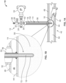
Fig. 1A is a side elevational view of an embodiment of a probe assembly of the disclosure and a cross-sectional view of a portion of a vacuum jacket pipe assembly prior to liquid flow through the vacuum jacket pipe assembly. -
Fig. 1B is an enlarged cross-sectional view of the interface of the probe assembly ofFig. 1A with the vacuum jacket pipe assembly ofFig. 1A . -
Fig. 2A is a side elevational view of the probe assembly and vacuum jacket pipe assembly ofFig. 1A with the vacuum jacket pipe assembly containing a liquid stream. -
Fig. 2B is an enlarged cross-sectional view of the interface of the probe assembly ofFig. 2A with the vacuum jacket pipe assembly ofFig. 2A . -
Fig. 3 is a graph of density vs. saturation pressure for liquid hydrogen. - An embodiment of the flowing liquid density measurement system is indicated in general at 10 in
Figs. 1A and2A . The system includes a probe assembly, indicated in general at 12 inFigs. 1A and2A . While the embodiments are described below in terms of hydrogen as the flowing liquid, it is to be understood that embodiments of the disclosure may be used to measure the density of other flowing liquids, including both those that are cryogenic and those that are not cryogenic. - As illustrated in
Fig. 1A , theprobe 12 includes an elongated bulb, indicated in general at 14. The bulb includes adistal tip portion 16 and aproximal portion 18. Theprobe 12 also includes amanifold 22 to which the proximal portion of the bulb is attached. Avent valve 24 is also attached to themanifold 22 and, as an example only, may be a burst disk valve. Acharging valve 26 having acharging port 28 is also attached to the manifold, as is apressure transmitter 32. Themanifold 22 includes interior passages that are in fluid communication with each other as well as with thebulb 14,vent valve 24,charging valve 26 andcharging port 28. - A vacuum jacket pipe assembly, a portion of which is indicated in general at 42 in
Figs. 1A and2A , directs a stream of liquid from a source to a destination. As an example only, the source may be a vacuum storage tank and the destination may be a use device or an industrial process. The vacuumjacket pipe assembly 42 features aninner pipe 44 surrounded by ajacket 46. Theannular space 48 defined therebetween preferably contains a vacuum or is at a near vacuum pressure level. The inner pipe includes aflow passage 50. - A port is formed in the vacuum jacket pipe assembly and includes an
outer sleeve 52, an inner sleeve 53 (Fig. 1B ) and an end cap fitting 54 having a central opening that communicates with a port central bore (that is surrounded by inner sleeve 53). The annularinterior space 56 of the port between theinner sleeve 53 and theouter sleeve 52 is in fluid communication with theannular space 48 between theinner piper 44 andjacket 46. As a result, the portinterior space 56 is also at or near vacuum level so as to be well insulated. - The
probe assembly 12 is installed in the vacuumjacket pipe assembly 42 by inserting thebulb 14 of the probe assembly into and through the central opening of the end cap fitting 54 and the central bore of the port until thedistal tip portion 16 of the bulb is positioned within theflow passage 50 of the vacuumjacket pipe assembly 42, as illustrated inFigs. 1A and 1B . - An
attachment member 62 is provided on the manifold and engages the end cap fitting 54 of the port of the vacuum jacket piper assembly so that theport assembly 12 is removably secured to thejacket pipe assembly 42. As an example only, theattachment member 62 of the probe assembly and the end cap fitting 54 of the vacuum jacket pipe assembly may include threads so that a threaded connection is formed. - In an alternative embodiment, the probe may be permanently installed with respect to the vacuum jacket pipe assembly with the
distal tip portion 16 of the bulb positioned within theflow passage 50 of the vacuumjacket pipe assembly 42. Such an embodiment eliminates the need for the outer and inner sleeves (52 and 53) as well as theend cap fitting 54. - With reference to
Fig. 1B , thebulb 14 includes abulb chamber 72 that is pressurized. Thebulb chamber 72 is in fluid communication with the passages of themanifold 22 ofFig. 1A . In the embodiment where hydrogen is the liquid that flows through theflow passage 50 of the pipe, thebulb chamber 72 contains hydrogen vapor. As an example only, thechamber 72 is pressurized to approximately 3.44 MPa (500 psi). In alternative embodiments, the bulb may include an alternative vapor and pressure. - The vapor within the
bulb chamber 72 preferably matches the liquid flowing through flow passage 50 (as in the illustrated embodiment, where thechamber 72 includes hydrogen vapor and liquid hydrogen flows through flow passage 50), but embodiments may exist where different fluids may be used within thechamber 72 and theflow passage 50. - The
chamber 72 of thebulb 14 may be charged with pressurized vapor by connecting a source of pressurized hydrogen vapor to the chargingport 28 andopening charging valve 26. When thechamber 72 has been filled with hydrogen vapor and reaches the appropriate pressure, thevalve 26 is closed, and the source of pressurized hydrogen is disconnected from chargingport 28. - If the vapor within the
chamber 72 ofbulb 14 is warmed and exceeds a predetermined pressure level, thesafety valve 24 automatically opens and vents vapor from within the chamber to atmosphere. - In
Fig. 2A , a stream of pressurizedliquid hydrogen 76 flows through theflow passage 50 of the vacuumjacket pipe assembly 42. Thedistal tip portion 16 of thebulb 14 of theprobe assembly 10 therefore is surrounded by thecold hydrogen liquid 76. With reference toFig. 2B , this causes a portion of the hydrogen vapor within thechamber 72 of the bulb to condense so thatcondensed vapor 74 puddles or collects in the bottom of thedistal tip portion 16. This causes the pressure within thechamber 72 to drop to the saturation pressure corresponding to the temperature of the liquid hydrogen within theflow passage 50. As a result, the pressure within thechamber 72 corresponds to the saturation pressure of the liquid hydrogen within theflow passage 50. - The pressure within the
chamber 72 is detected by the pressure transmitter 32 (which also includes pressure detection capability), and is transmitted to a controller (not shown), which may include a microprocessor or other computer device. As an example only, the pressure transmitter may receive power from an onboard battery or an external electrical source. Furthermore, as an example only, a suitable controller includes the FlowCom 3000 controller available from Flow Instruments & Engineering GmbH of Monheim, Germany. The pressure transmission may take place by wireless transmission or by wire. - As is known in the art, and illustrated in
Fig. 3 , once the saturation pressure of a fluid such as liquid hydrogen, is known, the density of the liquid may be determined using density vs. saturation data for the fluid. Upon receipt of the pressure data from thepressure transmitter 32, the controller is programmed to use a combination of polynominals and lookup tables to calculate the temperature and density of the liquid hydrogen stream within theflow passage 50. The controller may then display the temperature and density of the fluid to a user. Alternatively or in addition, the controller may use the received and calculated data to determine a flow rate of the liquid hydrogen withinflow passage 50 using equations known in the art. - In some embodiments, the saturation pressure may be used by the controller to first calculate temperature (since the type of fluid is known) with the density calculation following as a second step. The density calculation may optionally be in conjunction with the line pressure within the
flow passage 50 of the vacuum pipe assembly so as to take into account the compressibility of the fluid. Such a system requires a second pressure transmitter, such as 32 ofFigs. 1A and2A , to determine the pressure withinflow passage 50. There are several polynominals which enable the controller to calculate the fluid density based on temperature for different pressures. Interpolation is then used to determine the density based upon the exact line pressure reading. Alternatively, a lookup-table may also be used as input data for interpolation. - It is to be understood that the saturation pressure of the liquid hydrogen within the
passage 50 of thevacuum pipe assembly 42 ofFigs. 2A and 2B could also be determined if the liquid hydrogen within the passage is in a static, non-flowing condition. - As an example only, in view of the above, embodiments of the disclosure may find use in flow meter designs for hydrogen service. In addition, the above embodiments are robust and rechargeable in the field and leverage transmitter electrical classification (Class 1 div 1 or div 2).
- While the preferred embodiments of the invention have been shown and described, it will be apparent to those skilled in the art that changes and modifications may be made therein without departing from the scope defined by the appended claims.
Claims (15)
- A system for determining a saturation pressure of a liquid comprising:a) a probe assembly (12) including:i) a manifold (22) having at internal passage;ii) an elongated bulb (14) defining a chamber and including a distal tip portion (16) and a proximal portion (18), said bulb secured to the manifold by the proximal portion with the chamber containing a pressurized vapor and in fluid communication with the internal passage;iii) a charging port (28) selectively in fluid communication with the internal passage of the manifold; andiv) a pressure transmitter (32) configured to detect a pressure within the chamber of the elongated bulb;b) a jacketed pipe assembly (42) including:i. a pipe (44) defining a flow passage (50);ii. a jacket (46) surrounding the pipe so that a first annular space (48) is formed, said annular space being at least partially evacuated of air;iii. a probe port to which said probe assembly is attached and configured so that the distal tip portion of the bulb is positioned within the flow passage of the pipe, said probe port including an inner sleeve (53) defining a central bore that is configured to receive the elongated bulb, an end cap fitting (54) having a central opening configured to receive the elongated bulb and an outer sleeve (52) surrounding the inner sleeve so that a second annular space (56) is defined between the inner and outer sleeves and the end cap fitting, wherein the second annular space in fluid communication with the first annular space and wherein the probe assembly is removably attached to the end cap fitting by an attachment member (62).
- The system of claim 1 further comprising a safety valve (24) connected to the manifold (22) and in fluid communication with the internal passage.
- The system of claim 2 wherein the safety valve (24) includes a burst disk.
- The system of claim 1 wherein the pressure transmitter (32) is mounted to the manifold (22).
- The system of claim 1 wherein the charging port (28) is configured to be attached to a supply of pressurized vapor and further comprising a charging valve (26) connected between the charging port (28) and the manifold (22), said charging valve configured to be moved between an open position, wherein the charging port is in fluid communication with the chamber so that the chamber receives pressurized vapor, and a closed position, wherein the charging port is not in fluid communication with the chamber.
- The system of claim 1 wherein the chamber is filled with a pressurized vapor.
- The system of claim 6 wherein the pressurized vapor is a cryogenic vapor.
- The system of claim 7 wherein the cryogenic vapor is hydrogen vapor.
- The system of claim 1 wherein the pressure transmitter (32) is configured to transmit a detected pressure to a remote controller.
- The system of claim 1 further comprising a controller, wherein the pressure transmitter (32) is configured to transmit a detected pressure to the controller and the controller is configured to determine a temperature and a density from the detected pressure.
- The system of claim 1 wherein the liquid is liquid hydrogen and the pressurized vapor is pressurized hydrogen vapor.
- The system of claim 1, wherein the attachment member (62) including threads so that a threaded connection is formed between the probe assembly (12) and the end cap fitting (54).
- A method of determining a saturation pressure of a liquid in a passage using the system according to any one of claims 1 to 12, the method comprising:a) placing the elongated bulb containing the pressurized vapor into the passage, wherein the vapor and the liquid are the same fluid;b) detecting a pressure of the pressurized vapor after the bulb is placed within the passage.
- The method of claim 13 wherein the fluid is hydrogen.
- The method of claim 13 further comprising the step of transmitting the detected pressure to a remote controller, optionally further comprising the steps of calculating a temperature and a density using the detected pressure and the controller.
Applications Claiming Priority (2)
| Application Number | Priority Date | Filing Date | Title |
|---|---|---|---|
| US202062987477P | 2020-03-10 | 2020-03-10 | |
| PCT/US2021/018656 WO2021183271A1 (en) | 2020-03-10 | 2021-02-19 | Liquid density measurement device, system and method |
Publications (3)
| Publication Number | Publication Date |
|---|---|
| EP4118413A1 EP4118413A1 (en) | 2023-01-18 |
| EP4118413B1 true EP4118413B1 (en) | 2025-04-09 |
| EP4118413C0 EP4118413C0 (en) | 2025-04-09 |
Family
ID=74875284
Family Applications (1)
| Application Number | Title | Priority Date | Filing Date |
|---|---|---|---|
| EP21712287.8A Active EP4118413B1 (en) | 2020-03-10 | 2021-02-19 | Liquid density measurement device, system and method |
Country Status (8)
| Country | Link |
|---|---|
| US (1) | US12379294B2 (en) |
| EP (1) | EP4118413B1 (en) |
| JP (1) | JP7669383B2 (en) |
| CN (1) | CN115836202A (en) |
| AU (1) | AU2021234216B2 (en) |
| CA (1) | CA3170954A1 (en) |
| MX (1) | MX2022011213A (en) |
| WO (1) | WO2021183271A1 (en) |
Families Citing this family (1)
| Publication number | Priority date | Publication date | Assignee | Title |
|---|---|---|---|---|
| CN117268991B (en) * | 2023-08-07 | 2024-04-16 | 北京航天试验技术研究所 | Hydrogen density measuring device and method |
Family Cites Families (12)
| Publication number | Priority date | Publication date | Assignee | Title |
|---|---|---|---|---|
| US3225174A (en) * | 1962-08-10 | 1965-12-21 | Cryovac Inc | Apparatus for maintaining constant the temperature of a flow of cryogenic gas |
| JPS58173457A (en) * | 1982-04-01 | 1983-10-12 | ブラウン・ボベリ・レアクトル・ゲ−・エム・ベ−・ハ− | Method and device for monitoring thermodynamical state of heated liquid in sealed system |
| JPH0623676B2 (en) * | 1984-09-27 | 1994-03-30 | 株式会社島津製作所 | Adsorption amount measuring device |
| US4901559A (en) | 1986-07-18 | 1990-02-20 | Werner Grabner | Method and arrangement for measuring the vapor pressure of liquids |
| JP3047552B2 (en) * | 1991-09-24 | 2000-05-29 | 株式会社島津製作所 | Adsorption amount measuring device |
| CN200941073Y (en) * | 2005-10-11 | 2007-08-29 | 于海龙 | Liquid nitrogen saturated vapour pressure |
| FR2931213A1 (en) * | 2008-05-16 | 2009-11-20 | Air Liquide | DEVICE AND METHOD FOR PUMPING A CRYOGENIC FLUID |
| KR20100047055A (en) * | 2008-10-28 | 2010-05-07 | 현대자동차주식회사 | System and method for measuring flow rate of recirculation hydrogen for fuel cell vehicle |
| US9869429B2 (en) * | 2010-08-25 | 2018-01-16 | Chart Industries, Inc. | Bulk cryogenic liquid pressurized dispensing system and method |
| US8910514B2 (en) * | 2012-02-24 | 2014-12-16 | Schlumberger Technology Corporation | Systems and methods of determining fluid properties |
| CN203869984U (en) * | 2014-07-24 | 2014-10-08 | 金子豪 | Testing device for liquid saturated vapor pressure |
| US9791429B2 (en) * | 2014-11-05 | 2017-10-17 | Ecolab Usa Inc. | Sensor system and method for sensing chlorine concentration |
-
2021
- 2021-02-19 CN CN202180027239.6A patent/CN115836202A/en active Pending
- 2021-02-19 AU AU2021234216A patent/AU2021234216B2/en active Active
- 2021-02-19 CA CA3170954A patent/CA3170954A1/en active Pending
- 2021-02-19 MX MX2022011213A patent/MX2022011213A/en unknown
- 2021-02-19 JP JP2022554902A patent/JP7669383B2/en active Active
- 2021-02-19 US US17/908,996 patent/US12379294B2/en active Active
- 2021-02-19 WO PCT/US2021/018656 patent/WO2021183271A1/en not_active Ceased
- 2021-02-19 EP EP21712287.8A patent/EP4118413B1/en active Active
Also Published As
| Publication number | Publication date |
|---|---|
| BR112022018029A2 (en) | 2022-11-16 |
| AU2021234216B2 (en) | 2026-03-05 |
| CN115836202A (en) | 2023-03-21 |
| CA3170954A1 (en) | 2021-09-16 |
| EP4118413A1 (en) | 2023-01-18 |
| MX2022011213A (en) | 2022-10-07 |
| EP4118413C0 (en) | 2025-04-09 |
| JP7669383B2 (en) | 2025-04-28 |
| US12379294B2 (en) | 2025-08-05 |
| JP2023519177A (en) | 2023-05-10 |
| WO2021183271A1 (en) | 2021-09-16 |
| US20230102872A1 (en) | 2023-03-30 |
| AU2021234216A1 (en) | 2022-10-06 |
Similar Documents
| Publication | Publication Date | Title |
|---|---|---|
| CN101454609B (en) | Method for filling at least one compressed gas tank with at least one gas, connector for connecting to an opening of a compressed gas tank, and compressed gas cylinder valve | |
| HU223727B1 (en) | Flow regulation fitting | |
| AU2018267576A1 (en) | Pressurized fluid container with strain gauge and remote communication means | |
| US7444854B2 (en) | Leak indicator with test leak and test leak for integration into a leak detector | |
| AU2021234216B2 (en) | Liquid density measurement device, system and method | |
| EP2583113B1 (en) | Methods and apparatus for filling superconductive magnets | |
| CA2341131C (en) | Valve assembly, pressure testing apparatus and testing method for propane tank systems | |
| US7168287B2 (en) | Reference leakage device for leak sniffer detector | |
| US6651486B1 (en) | Standup pressure testing device and method | |
| US9366386B2 (en) | Liquid level gauge for a cryogenic fluid cylinder | |
| CA2704839A1 (en) | Pressure testing apparatus for gas service delivery systems | |
| US20170336233A1 (en) | Method for determining a gas amount and device for carrying out said method | |
| CN106289372B (en) | Welded insulated gas cylinder Daily boil-off-rate measuring instrument test method | |
| FI123192B (en) | pRESSURE gAUGE | |
| US6223766B1 (en) | Pressure testing apparatus and testing method for propane tank systems | |
| US20220244089A1 (en) | Device And Method For Sensing Information Relating To The Fill Level Of A Container Storing Fluid | |
| KR101639033B1 (en) | Temperature and Volume Measuring System of Fuel Tank at Vehicle by using Gas Pump | |
| BR112022018029B1 (en) | SYSTEM FOR DETERMINING THE SATURATION PRESSURE OF A LIQUID | |
| US20030101798A1 (en) | Helicopter hollow blade pressure check and fill apparatus and method to use same | |
| EP3708898A1 (en) | A gas cylinder monitoring system | |
| KR101663541B1 (en) | Temperature and Revised Volume Measuring System of Fuel Tank at Vehicle | |
| EP4189336B1 (en) | Flow meter assembly | |
| CN220018777U (en) | Temperature sensor for ISO TANK | |
| WO2001071294A1 (en) | Method and device for control of delivery of temperature-sensitive hydrocarbons | |
| AU2002100326A4 (en) | Method and device for control of delivery of temperature-sensitive hydrocarbons |
Legal Events
| Date | Code | Title | Description |
|---|---|---|---|
| STAA | Information on the status of an ep patent application or granted ep patent |
Free format text: STATUS: UNKNOWN |
|
| STAA | Information on the status of an ep patent application or granted ep patent |
Free format text: STATUS: THE INTERNATIONAL PUBLICATION HAS BEEN MADE |
|
| PUAI | Public reference made under article 153(3) epc to a published international application that has entered the european phase |
Free format text: ORIGINAL CODE: 0009012 |
|
| STAA | Information on the status of an ep patent application or granted ep patent |
Free format text: STATUS: REQUEST FOR EXAMINATION WAS MADE |
|
| 17P | Request for examination filed |
Effective date: 20220911 |
|
| AK | Designated contracting states |
Kind code of ref document: A1 Designated state(s): AL AT BE BG CH CY CZ DE DK EE ES FI FR GB GR HR HU IE IS IT LI LT LU LV MC MK MT NL NO PL PT RO RS SE SI SK SM TR |
|
| DAV | Request for validation of the european patent (deleted) | ||
| DAX | Request for extension of the european patent (deleted) | ||
| GRAP | Despatch of communication of intention to grant a patent |
Free format text: ORIGINAL CODE: EPIDOSNIGR1 |
|
| STAA | Information on the status of an ep patent application or granted ep patent |
Free format text: STATUS: GRANT OF PATENT IS INTENDED |
|
| INTG | Intention to grant announced |
Effective date: 20241004 |
|
| GRAS | Grant fee paid |
Free format text: ORIGINAL CODE: EPIDOSNIGR3 |
|
| GRAA | (expected) grant |
Free format text: ORIGINAL CODE: 0009210 |
|
| STAA | Information on the status of an ep patent application or granted ep patent |
Free format text: STATUS: THE PATENT HAS BEEN GRANTED |
|
| AK | Designated contracting states |
Kind code of ref document: B1 Designated state(s): AL AT BE BG CH CY CZ DE DK EE ES FI FR GB GR HR HU IE IS IT LI LT LU LV MC MK MT NL NO PL PT RO RS SE SI SK SM TR |
|
| REG | Reference to a national code |
Ref country code: GB Ref legal event code: FG4D |
|
| REG | Reference to a national code |
Ref country code: CH Ref legal event code: EP |
|
| REG | Reference to a national code |
Ref country code: DE Ref legal event code: R096 Ref document number: 602021028884 Country of ref document: DE |
|
| REG | Reference to a national code |
Ref country code: IE Ref legal event code: FG4D |
|
| U01 | Request for unitary effect filed |
Effective date: 20250422 |
|
| U07 | Unitary effect registered |
Designated state(s): AT BE BG DE DK EE FI FR IT LT LU LV MT NL PT RO SE SI Effective date: 20250425 |
|
| PG25 | Lapsed in a contracting state [announced via postgrant information from national office to epo] |
Ref country code: ES Free format text: LAPSE BECAUSE OF FAILURE TO SUBMIT A TRANSLATION OF THE DESCRIPTION OR TO PAY THE FEE WITHIN THE PRESCRIBED TIME-LIMIT Effective date: 20250409 |
|
| PG25 | Lapsed in a contracting state [announced via postgrant information from national office to epo] |
Ref country code: GR Free format text: LAPSE BECAUSE OF FAILURE TO SUBMIT A TRANSLATION OF THE DESCRIPTION OR TO PAY THE FEE WITHIN THE PRESCRIBED TIME-LIMIT Effective date: 20250710 Ref country code: NO Free format text: LAPSE BECAUSE OF FAILURE TO SUBMIT A TRANSLATION OF THE DESCRIPTION OR TO PAY THE FEE WITHIN THE PRESCRIBED TIME-LIMIT Effective date: 20250709 |
|
| PG25 | Lapsed in a contracting state [announced via postgrant information from national office to epo] |
Ref country code: PL Free format text: LAPSE BECAUSE OF FAILURE TO SUBMIT A TRANSLATION OF THE DESCRIPTION OR TO PAY THE FEE WITHIN THE PRESCRIBED TIME-LIMIT Effective date: 20250409 |
|
| PG25 | Lapsed in a contracting state [announced via postgrant information from national office to epo] |
Ref country code: HR Free format text: LAPSE BECAUSE OF FAILURE TO SUBMIT A TRANSLATION OF THE DESCRIPTION OR TO PAY THE FEE WITHIN THE PRESCRIBED TIME-LIMIT Effective date: 20250409 |
|
| PG25 | Lapsed in a contracting state [announced via postgrant information from national office to epo] |
Ref country code: RS Free format text: LAPSE BECAUSE OF FAILURE TO SUBMIT A TRANSLATION OF THE DESCRIPTION OR TO PAY THE FEE WITHIN THE PRESCRIBED TIME-LIMIT Effective date: 20250709 |
|
| PG25 | Lapsed in a contracting state [announced via postgrant information from national office to epo] |
Ref country code: IS Free format text: LAPSE BECAUSE OF FAILURE TO SUBMIT A TRANSLATION OF THE DESCRIPTION OR TO PAY THE FEE WITHIN THE PRESCRIBED TIME-LIMIT Effective date: 20250809 |
|
| PG25 | Lapsed in a contracting state [announced via postgrant information from national office to epo] |
Ref country code: SM Free format text: LAPSE BECAUSE OF FAILURE TO SUBMIT A TRANSLATION OF THE DESCRIPTION OR TO PAY THE FEE WITHIN THE PRESCRIBED TIME-LIMIT Effective date: 20250409 |
|
| PG25 | Lapsed in a contracting state [announced via postgrant information from national office to epo] |
Ref country code: SK Free format text: LAPSE BECAUSE OF FAILURE TO SUBMIT A TRANSLATION OF THE DESCRIPTION OR TO PAY THE FEE WITHIN THE PRESCRIBED TIME-LIMIT Effective date: 20250409 |
|
| PLBE | No opposition filed within time limit |
Free format text: ORIGINAL CODE: 0009261 |
|
| STAA | Information on the status of an ep patent application or granted ep patent |
Free format text: STATUS: NO OPPOSITION FILED WITHIN TIME LIMIT |
|
| REG | Reference to a national code |
Ref country code: CH Ref legal event code: L10 Free format text: ST27 STATUS EVENT CODE: U-0-0-L10-L00 (AS PROVIDED BY THE NATIONAL OFFICE) Effective date: 20260218 |
|
| REG | Reference to a national code |
Ref country code: CH Ref legal event code: U11 Free format text: ST27 STATUS EVENT CODE: U-0-0-U10-U11 (AS PROVIDED BY THE NATIONAL OFFICE) Effective date: 20260301 |
|
| 26N | No opposition filed |
Effective date: 20260112 |
|
| U20 | Renewal fee for the european patent with unitary effect paid |
Year of fee payment: 6 Effective date: 20260227 |
|
| PGFP | Annual fee paid to national office [announced via postgrant information from national office to epo] |
Ref country code: GB Payment date: 20260227 Year of fee payment: 6 |
|
| PGFP | Annual fee paid to national office [announced via postgrant information from national office to epo] |
Ref country code: IE Payment date: 20260227 Year of fee payment: 6 |
|
| PGFP | Annual fee paid to national office [announced via postgrant information from national office to epo] |
Ref country code: CZ Payment date: 20260205 Year of fee payment: 6 Ref country code: CH Payment date: 20260301 Year of fee payment: 6 |
|
| U1N | Appointed representative for the unitary patent procedure changed after the registration of the unitary effect |
Representative=s name: MARKS & CLERK LLP; GB |