EP4118352B1 - Method for replacing a sliding pad of a rotational sliding bearing, sliding bearing and wind turbine - Google Patents
Method for replacing a sliding pad of a rotational sliding bearing, sliding bearing and wind turbine Download PDFInfo
- Publication number
- EP4118352B1 EP4118352B1 EP21721100.2A EP21721100A EP4118352B1 EP 4118352 B1 EP4118352 B1 EP 4118352B1 EP 21721100 A EP21721100 A EP 21721100A EP 4118352 B1 EP4118352 B1 EP 4118352B1
- Authority
- EP
- European Patent Office
- Prior art keywords
- bearing
- sliding
- actuator
- stationary part
- rotatable part
- Prior art date
- Legal status (The legal status is an assumption and is not a legal conclusion. Google has not performed a legal analysis and makes no representation as to the accuracy of the status listed.)
- Active
Links
- 238000000034 method Methods 0.000 title claims description 30
- 238000003780 insertion Methods 0.000 claims description 9
- 230000037431 insertion Effects 0.000 claims description 9
- 238000004381 surface treatment Methods 0.000 claims description 9
- 238000006073 displacement reaction Methods 0.000 description 13
- 238000003801 milling Methods 0.000 description 9
- 239000012530 fluid Substances 0.000 description 6
- 238000012423 maintenance Methods 0.000 description 5
- 230000008878 coupling Effects 0.000 description 3
- 238000010168 coupling process Methods 0.000 description 3
- 238000005859 coupling reaction Methods 0.000 description 3
- 238000004140 cleaning Methods 0.000 description 1
- 238000011109 contamination Methods 0.000 description 1
- 238000005260 corrosion Methods 0.000 description 1
- 230000007797 corrosion Effects 0.000 description 1
- 239000000428 dust Substances 0.000 description 1
- 230000000694 effects Effects 0.000 description 1
- 238000011065 in-situ storage Methods 0.000 description 1
- 238000003754 machining Methods 0.000 description 1
- 239000000463 material Substances 0.000 description 1
- 230000000284 resting effect Effects 0.000 description 1
- 238000009966 trimming Methods 0.000 description 1
Images


Classifications
-
- F—MECHANICAL ENGINEERING; LIGHTING; HEATING; WEAPONS; BLASTING
- F16—ENGINEERING ELEMENTS AND UNITS; GENERAL MEASURES FOR PRODUCING AND MAINTAINING EFFECTIVE FUNCTIONING OF MACHINES OR INSTALLATIONS; THERMAL INSULATION IN GENERAL
- F16C—SHAFTS; FLEXIBLE SHAFTS; ELEMENTS OR CRANKSHAFT MECHANISMS; ROTARY BODIES OTHER THAN GEARING ELEMENTS; BEARINGS
- F16C43/00—Assembling bearings
- F16C43/02—Assembling sliding-contact bearings
-
- F—MECHANICAL ENGINEERING; LIGHTING; HEATING; WEAPONS; BLASTING
- F03—MACHINES OR ENGINES FOR LIQUIDS; WIND, SPRING, OR WEIGHT MOTORS; PRODUCING MECHANICAL POWER OR A REACTIVE PROPULSIVE THRUST, NOT OTHERWISE PROVIDED FOR
- F03D—WIND MOTORS
- F03D80/00—Details, components or accessories not provided for in groups F03D1/00 - F03D17/00
- F03D80/50—Maintenance or repair
-
- F—MECHANICAL ENGINEERING; LIGHTING; HEATING; WEAPONS; BLASTING
- F16—ENGINEERING ELEMENTS AND UNITS; GENERAL MEASURES FOR PRODUCING AND MAINTAINING EFFECTIVE FUNCTIONING OF MACHINES OR INSTALLATIONS; THERMAL INSULATION IN GENERAL
- F16C—SHAFTS; FLEXIBLE SHAFTS; ELEMENTS OR CRANKSHAFT MECHANISMS; ROTARY BODIES OTHER THAN GEARING ELEMENTS; BEARINGS
- F16C17/00—Sliding-contact bearings for exclusively rotary movement
- F16C17/02—Sliding-contact bearings for exclusively rotary movement for radial load only
- F16C17/03—Sliding-contact bearings for exclusively rotary movement for radial load only with tiltably-supported segments, e.g. Michell bearings
-
- F—MECHANICAL ENGINEERING; LIGHTING; HEATING; WEAPONS; BLASTING
- F03—MACHINES OR ENGINES FOR LIQUIDS; WIND, SPRING, OR WEIGHT MOTORS; PRODUCING MECHANICAL POWER OR A REACTIVE PROPULSIVE THRUST, NOT OTHERWISE PROVIDED FOR
- F03D—WIND MOTORS
- F03D80/00—Details, components or accessories not provided for in groups F03D1/00 - F03D17/00
- F03D80/70—Bearing or lubricating arrangements
-
- F—MECHANICAL ENGINEERING; LIGHTING; HEATING; WEAPONS; BLASTING
- F16—ENGINEERING ELEMENTS AND UNITS; GENERAL MEASURES FOR PRODUCING AND MAINTAINING EFFECTIVE FUNCTIONING OF MACHINES OR INSTALLATIONS; THERMAL INSULATION IN GENERAL
- F16C—SHAFTS; FLEXIBLE SHAFTS; ELEMENTS OR CRANKSHAFT MECHANISMS; ROTARY BODIES OTHER THAN GEARING ELEMENTS; BEARINGS
- F16C39/00—Relieving load on bearings
- F16C39/02—Relieving load on bearings using mechanical means
-
- F—MECHANICAL ENGINEERING; LIGHTING; HEATING; WEAPONS; BLASTING
- F05—INDEXING SCHEMES RELATING TO ENGINES OR PUMPS IN VARIOUS SUBCLASSES OF CLASSES F01-F04
- F05B—INDEXING SCHEME RELATING TO WIND, SPRING, WEIGHT, INERTIA OR LIKE MOTORS, TO MACHINES OR ENGINES FOR LIQUIDS COVERED BY SUBCLASSES F03B, F03D AND F03G
- F05B2230/00—Manufacture
- F05B2230/80—Repairing, retrofitting or upgrading methods
-
- F—MECHANICAL ENGINEERING; LIGHTING; HEATING; WEAPONS; BLASTING
- F05—INDEXING SCHEMES RELATING TO ENGINES OR PUMPS IN VARIOUS SUBCLASSES OF CLASSES F01-F04
- F05B—INDEXING SCHEME RELATING TO WIND, SPRING, WEIGHT, INERTIA OR LIKE MOTORS, TO MACHINES OR ENGINES FOR LIQUIDS COVERED BY SUBCLASSES F03B, F03D AND F03G
- F05B2240/00—Components
- F05B2240/50—Bearings
- F05B2240/53—Hydrodynamic or hydrostatic bearings
-
- F—MECHANICAL ENGINEERING; LIGHTING; HEATING; WEAPONS; BLASTING
- F16—ENGINEERING ELEMENTS AND UNITS; GENERAL MEASURES FOR PRODUCING AND MAINTAINING EFFECTIVE FUNCTIONING OF MACHINES OR INSTALLATIONS; THERMAL INSULATION IN GENERAL
- F16C—SHAFTS; FLEXIBLE SHAFTS; ELEMENTS OR CRANKSHAFT MECHANISMS; ROTARY BODIES OTHER THAN GEARING ELEMENTS; BEARINGS
- F16C2237/00—Repair or replacement
-
- F—MECHANICAL ENGINEERING; LIGHTING; HEATING; WEAPONS; BLASTING
- F16—ENGINEERING ELEMENTS AND UNITS; GENERAL MEASURES FOR PRODUCING AND MAINTAINING EFFECTIVE FUNCTIONING OF MACHINES OR INSTALLATIONS; THERMAL INSULATION IN GENERAL
- F16C—SHAFTS; FLEXIBLE SHAFTS; ELEMENTS OR CRANKSHAFT MECHANISMS; ROTARY BODIES OTHER THAN GEARING ELEMENTS; BEARINGS
- F16C2360/00—Engines or pumps
- F16C2360/31—Wind motors
-
- Y—GENERAL TAGGING OF NEW TECHNOLOGICAL DEVELOPMENTS; GENERAL TAGGING OF CROSS-SECTIONAL TECHNOLOGIES SPANNING OVER SEVERAL SECTIONS OF THE IPC; TECHNICAL SUBJECTS COVERED BY FORMER USPC CROSS-REFERENCE ART COLLECTIONS [XRACs] AND DIGESTS
- Y02—TECHNOLOGIES OR APPLICATIONS FOR MITIGATION OR ADAPTATION AGAINST CLIMATE CHANGE
- Y02E—REDUCTION OF GREENHOUSE GAS [GHG] EMISSIONS, RELATED TO ENERGY GENERATION, TRANSMISSION OR DISTRIBUTION
- Y02E10/00—Energy generation through renewable energy sources
- Y02E10/70—Wind energy
- Y02E10/72—Wind turbines with rotation axis in wind direction
Definitions
- the invention relates to a method for replacing a sliding pad of a rotational sliding bearing, wherein the bearing comprises a plurality of sliding pads each supporting an annular rotatable part of the bearing on a stationary part of the bearing in an axial direction and/or a radial direction. Furthermore, the invention relates to a sliding bearing and a wind turbine.
- rotatable components like the hub or a rotatable shaft have to be supported on the stationary parts of the wind turbine. Therefore, one or more bearings are used. Due to the loads, which act on the rotatable parts of the wind turbine during operation, a bearing used to support the rotatable components of the wind turbine on the stationary components may suffer from wear or damage so that repair procedures and/or maintenance procedures for maintaining the functionality of the bearing involving a removal of the bearing from the wind turbine are frequently required. However, due to the size and the weight of the bearings, especially of a main bearing of a wind turbine, these procedures may be tedious and involve external cranes and, in the case of offshore wind turbines, also the usage of vessels for supporting the external crane used for removal and/or replacement of the bearing.
- EP 3 460 272 A1 a method for changing a bearing component of a main bearing of a wind turbine is described.
- the bearing component is unloaded by mechanically moving the shaft, wherein the bearing component is then moved axially from or into its mounting position by means of a replacement tool device.
- EP 3 219 984 A1 relates to a sliding bearing arrangement for a wind turbine and a method to service the bearing.
- the sliding bearing arrangement comprises a stationary first shaft and a rotatable second shaft, which is arranged at an inner circumference of the stationary shaft. A replacement of the sliding pad occurs by sliding the bearing pads out of the gap between the stationary shaft and the rotatable shaft through the throughgoing openings in the collar.
- sliding pads between the stationary and the rotatable part of the bearing may be exchanged through radial openings in the inner part of the bearing.
- an exchange of tilting segments may be performed through an opening provided in the stationary part of the bearing.
- the rotatable part By usage of a hydraulic piston, the rotatable part may be lifted from the tilting segments to unload the tilting segments so that they may be removed through the opening.
- Replacements of sliding pads in wind turbine yaw bearings are also known from WO 2017/162250 A1 and EP 3 594 495 A1 .
- the bearing comprises a plurality of sliding pads each supporting an annual rotatable part of the bearing on a stationary part of the bearing in an axial direction and/or a radial direction
- the stationary part is annular and the rotatable part is arranged on a circumference of the stationary part
- the stationary part comprises a plurality of axial and/or radial openings arranged circumferentially and/or axially displaced in the circumference of the stationary part
- a sliding pad may comprise several components, e.g. an outer sliding part, a support part for attachment to a structure by bolts or similar, a tilting support part to ensure that the sliding pad is able to tilt and/or a resilient means like e.g. a spring to ensure a preloading of the sliding pad and the tilting support.
- the bearing may be in particular a fluid film bearing, wherein a fluid film is located between the sliding pads and the rotatable part, or the stationary part, respectively.
- the load of the rotatable part is removed from the sliding pad by applying a force to the rotatable part, so that one or more of the sliding pads become unloaded.
- the rotatable part is supported on the stationary part via the remainder of the sliding pads.
- the unloading of a sliding pad to be replaced occurs by applying a force in particular directly to the rotatable part, so that the rotatable part is lifted and/or displaced and the weight of the rotatable part is not supported anymore on the sliding pad to be replaced.
- the unloaded sliding pad can be removed in an axial and/or a radial direction of the bearing.
- the sliding pad can be removed in a radial inward direction to the centre of the bearing, hence in the direction of a centre point of the annular rotatable part.
- the sliding pad can be removed in a radial outward direction.
- a combination of an axial and a radial movement for removing the sliding pad is possible.
- the removal of the sliding pad at least partly in a radial direction has the advantage that no access, or a reduced access space, respectively, from the axial direction to the sliding bearing is required.
- both sliding pads that support the bearing in the axial direction and sliding pads that support the rotatable part in the radial direction on the stationary part can be removed at least partly in the radial direction facilitating the replacement of the sliding pad.
- a replacement sliding pad is inserted at the position of the removed sliding pad.
- the replacement sliding pad may be for instance a new sliding pad or it can be the removed sliding pad, which has been subject to maintenance and/or repair procedures, for instance cleaning procedures or the like. Also the insertion of the replacement sliding pad may occur in a radial direction, in particular in reverse direction to the removal of the sliding pad.
- the rotatable part of the bearing is supported on the replacement sliding pad by removing the force applied to the rotatable part.
- the force, which has been applied to the rotatable part for unloading the sliding pad, is removed, so that the rotatable part is supported on the sliding pad again.
- the method for replacing the sliding pad according to the invention has the advantage that the sliding pads can be exchanged in-situ and one by one, so that an exchange of the entire bearing is not required even if all sliding pads of the bearing have to be replaced.
- This facilitates the maintenance of the bearing, in particular for bearings used as main bearing in a wind turbine.
- Providing a plurality of sliding pads in the bearing allows for supporting the rotatable part on the stationary part on the remaining sliding pads of the bearing during the removal of the load of the rotatable part from one of the sliding pads, or a part of the sliding pads, respectively.
- This facilitates the repair and/or the maintenance of the sliding bearing since for instance a one-by-one replacement of damaged or worn sliding pads becomes possible.
- an updating of the bearing by replacing the mounted sliding pads by improved sliding pads as replacement pads is possible.
- the rotatable part is arranged on an outer circumference of the stationary part, wherein the sliding pad is replaced from an interior of the stationary part through an opening in the outer circumference of the stationary part.
- the replacement of the sliding pad from an interior of the stationary part hence the removal of the sliding pad and the insertion of a replacement sliding pad, has the advantage that the sliding pads are easily accessible from the interior of the stationary part, in particular when the bearing is used as a main bearing in a wind turbine.
- the stationary part may be for instance a hollow shaft, or connected to a hollow shaft, respectively, wherein the sliding pads are accessible from the interior of the hollow shaft through one or more openings in the outer circumference of the stationary part.
- the sliding pads which are arranged for instance between the outer circumference of the stationary part and the rotatable part arranged on an outer circumference of the stationary part and supported by the sliding pads on the stationary part, may be removed and/or replaced at least partly in a radial direction towards the interior, hence towards the centre, of the stationary part.
- the stationary part provides openings in its outer circumference, which allow to access the sliding pads. For instance, one corresponding opening per sliding pad may be provided.
- the size of the openings may correspond to the size of the respective sliding pads, so that each sliding pad may be moved through one of the openings towards the interior of the stationary part for the replacement.
- the sliding pad is fixed to the bearing by a bolted connection applying a force to the sliding pad, wherein the force is released by untightening of the bolted connection, and/or by a form-fit connection, wherein the sliding pad is arranged in a cavity or a recess of the stationary part.
- a bolted connection applying a force to the sliding pad, wherein the force is released by untightening of the bolted connection, and/or by a form-fit connection, wherein the sliding pad is arranged in a cavity or a recess of the stationary part.
- the bolted connection may apply a force to the sliding pad enabling a support of the rotatable part on the sliding pad.
- the sliding pad is fixed to the bearing by a form-fit connection, wherein the sliding pad is arranged in a cavity or a recess of the stationary part.
- the cavity or the recess may be in particular an integral part of the stationary part and may be located in particular in its outer circumference.
- the sliding pad may be fixed in the cavity or the recess, respectively, by the rotating part resting on the sliding pad.
- One side of the cavity, or the recess, respectively, may comprise an axial opening for replacement of an unloaded sliding pad, in particular a radially supporting sliding pad.
- the force is applied to the rotatable part using an actuator arrangement comprising at least one actuator, in particular at least one mechanical actuator and/or at least one hydraulic actuator.
- the at least one actuator of the actuator arrangement may push away the rotatable part from the sliding pad, so that the sliding pad is unloaded from the weight of the rotatable part. Therefore, already a small displacement, for instance about 1 mm, is sufficient.
- a force to the rotatable part can be applied prior to the replacement of the sliding pad and removed after replacement of the sliding pad, respectively.
- a hydraulic actuator for instance a hydraulic jack may be used.
- the actuator arrangement and/or the bearing may comprise a mechanical fixture device which fixes the rotatable part in its displaced position for securing it for instance in the event of a power loss of a hydraulic actuator.
- a mechanical fixture device which fixes the rotatable part in its displaced position for securing it for instance in the event of a power loss of a hydraulic actuator.
- mechanical actuator for instance a screw or a threaded bolt may be used to push away the rotatable part from the stationary part.
- at least one mechanical actuator and at least one hydraulic actuator are used, wherein the at least one mechanical actuator is used as mechanical fixture device to secure the rotatable part displaced by the at least one hydraulic actuator in the displaced position.
- an axial force on the rotatable part of the bearing for replacement of an axially supporting sliding pad and/or a radial force for replacement of a radially supporting sliding pad is applied by the actuator arrangement.
- a radial force may be applied to the rotatable part by the actuator arrangement unloading the radially supporting sliding pad.
- an axial force may be applied to the rotatable part by the actuator arrangement for unloading the axially supporting sliding pad.
- the actuator arrangement may comprise one or more radial actuators, which can apply each a radial force, and/or one or more axial actuators, which can apply each an axial force.
- At least one actuator of the actuator arrangement is detachably mounted to the bearing prior to the removal of the load from the sliding pad to be replaced and/or at least one actuator of the actuator arrangement is permanently mounted to the bearing.
- the unloading of the sliding pad can be conducted using an actuator arrangement which is permanently mounted to the bearing. This allows for instance to arrange the at least one actuator of the actuator arrangement inside a bearing case, so that the actuator can act directly on the rotatable part of the bearing.
- An actuator of the actuator arrangement mounted in the course of the replacement procedure may be attached for instance to an outer side of a bearing case of the bearing, wherein the force created by the at least one actuator is applied for instance by coupling a piston of the actuator to the rotatable part of the bearing.
- the actuator may be fixed on either the stationary part or the rotatable part, wherein the actuator is coupled to the respective other part allowing a displacement between the rotatable part and the stationary part of the bearing to unload one or more of the sliding pads.
- the piston of the actuator may be arranged inside an orifice of a bearing cover, the stationary part and/or the rotatable part, respectively.
- a surface treatment of a surface of the stationary part and/or a surface of the rotatable part is conducted prior to the insertion of the replacement sliding pad.
- the surface treatment may be for instance a surface milling operation conducted to clean and/or to repair a surface of the stationary part and/or a surface of the rotatable part. This allows to clean the surface at the position of the sliding pad, so that for instance dirt and/or residues from the sliding pad can be removed from the surfaces. Also corrosion and/or fretting effects can be removed by the surface treatment.
- a portable machining device may be mounted in the space where the sliding pad is usually mounted.
- the surface milling operation may be carried out for instance on an interface of the stationary part with the sliding pad to remove affected material.
- the milling device may include a cover arrangement adapted to the size of an opening of the outer circumference of the stationary part, in which the milling device is inserted.
- the cover arrangement the surface that is subject to the surface treatment may be covered to seal the treated surface from the surrounding, in particular from the interior of the bearing. This may prevent contamination of an interior of the bearing, hence an undesired intrusion of dust or the like created during the surface treatment into an interior of the bearing is inhibited advantageously.
- a sliding bearing according to the invention comprises an annular rotatable part, a stationary part and a plurality of sliding pads, wherein the stationary part is annular and the rotatable part is arranged on a circumference of the stationary part, wherein the rotatable part is supported on the stationary part by the sliding pads in a radial and/or an axial direction, wherein the stationary part comprises a plurality of axial and/or radial openings arranged circumferentially and/or axially displaced in the circumference of the stationary part, wherein the sliding pads are removable and/or insertable through the openings, wherein the bearing comprises an actuator arrangement with one or more actuators mounted to the sliding bearing, wherein the actuator arrangement is adapted for removing a load of the rotatable part from at least one of the sliding pads to be removed.
- the rotatable part may be arranged either on an inner circumference of the stationary part or on an outer circumference of the stationary part.
- one corresponding opening is provided in the circumference of the stationary part allowing a replacement of each of the sliding pads.
- Sliding pads, that support a rotatable part arranged on the outer circumference of the stationary part may be removed in a radial inward direction towards a centre point of the annular stationary part.
- sliding pads that support a rotatable part on the inner circumference of the stationary part, may be replaced in a radially outward direction through the openings in the circumference of the stationary part.
- Radially supporting sliding pads may be removed for instance from an inside of the bearing by moving them axially out of a cavity, or a recess, respectively, comprising an axial opening and housing the radially supporting sliding pad.
- a bearing is provided according to claim 8 which comprises an actuator arrangement with one or more actuators, in particular at least one mechanical actuator and/or at least one hydraulic actuator, wherein the actuator arrangement is adapted for removing a load of the rotatable part from at least one of the sliding pads.
- the at least one actuator of the actuator arrangement may be arranged inside a bearing case of the bearing. It is also possible that the at least one actuator is mounted to an outside of a bearing case of the bearing, wherein a coupling of the actuator towards the rotatable part and the stationary part occurs for instance via a piston.
- the bearing comprises at least one mechanical actuator and at least one hydraulic actuator, wherein the at least one mechanical actuator is used to secure the rotatable part displaced by the at least one hydraulic actuator in the displaced position.
- the at least one actuator of the actuator arrangement is arranged circumferentially displaced from the sliding pads.
- the sliding pads may be arranged between the stationary part and the rotatable part circumferentially and/or axially displaced for supporting the rotatable part both in the radial and/or the axial direction on the stationary part.
- the at least one actuator of the actuator arrangement is arranged circumferentially displaced from each of the sliding pads.
- the actuator arrangement comprises at least one radial actuator arranged at least partly in between the stationary part and the rotatable part for applying a radial force on the rotatable part and/or at least one axial actuator arranged at least partly between the rotatable part and a protrusion on the circumference of the stationary part for applying an axial force on the rotatable part.
- the protrusion may be for instance a bearing cover mounted to the stationary part or a protrusion of the circumference of the stationary part.
- the protrusion may protrude from the circumference in particular adjacently to the rotatable part, so that at least one actuator may be arranged between the protrusion and the rotatable part for applying a force on the rotatable part for unloading one or more of the sliding pads.
- the bearing comprises a bearing case, wherein the actuator arrangement is arranged inside the bearing case.
- the bearing case may be formed for instance at least partly by a bearing cover and/or the rotatable part and/or the stationary part, wherein the bearing case houses in particular the contact area between the sliding pads, the rotatable part and/or a fluid used in the bearing.
- the one or more actuators of the actuator arrangement each are fixed to the stationary part or the rotatable part of the bearing.
- the actuator fixed to one of the parts of the bearing may couple to the respective other part of the bearing to apply a force on the other part to create a displacement between the stationary part and the rotatable part causing an unloading of at least one of the sliding pads of the bearing.
- the at least one actuator may be attached directly or indirectly to the stationary part or the rotatable part, respectively.
- a wind turbine according to the invention comprises a sliding bearing according to the invention.
- the details and advantages of a sliding bearing according to the invention apply correspondingly.
- the details and advantages of a method for replacement a sliding pad of a rotational sliding bearing apply correspondingly.
- the wind turbine 1 comprises a sliding bearing 2, which supports a hub 3 on a stationary shaft 4 of the wind turbine.
- the sliding bearing 2 comprises an annular rotatable part 5, which is connected to the hub 3 of the wind turbine 1.
- the sliding bearing 2 comprises an annular stationary part 6, which is connected to the stationary shaft 4 of the wind turbine 1. It is possible that the stationary part 6 of the bearing is attached to the shaft 4 or that it is fabricated one-piece with the shaft 4.
- the sliding bearing 2 further comprises a plurality of radially supporting sliding pads 7 and a plurality of axially supporting sliding pads 8.
- the radially supporting sliding pads 7 support the rotatable part 5 of the bearing 2 on the stationary part 6 in a radial direction.
- the radially supporting sliding pads 8 support the rotatable part 5 of the sliding bearing in an axial direction on the stationary part 6.
- a fluid film may be arranged between the rotatable part 5 and the sliding pads 7, 8, arranged allowing a sliding of the rotatable part 5 on the sliding pads 7, 8 during operation of the wind turbine 1.
- the rotatable part 5 is arranged on an outer circumference of the stationary part 6.
- the stationary part 6 comprises a plurality of openings 9, 10, wherein a plurality of first openings 9 each correspond to one of the radially supporting sliding pad 7, and a plurality of second openings 10 each correspond to one of the axially supporting sliding pad 8.
- a radially supporting sliding pad 7 can be removed through the corresponding opening 9 in a radial direction towards the centre of the stationary part 6 of the bearing 2.
- an axially supporting sliding pad 8 can be removed through the corresponding opening 10 towards the centre of the stationary part 6.
- the sliding pads 7, 8 can then be transported out of the bearing 2, or the wind turbine 1, respectively, as indicated by the arrow 13.
- a replacement sliding pad can be inserted at a position of the removed sliding pad 7, 8 in a reverse movement.
- the replacement of the sliding pads 7, 8 may be performed manually and/or by usage of a lifting device manually installed prior to the replacement procedure in the vicinity of the bearing 2.
- the opening 9 is an axial opening of a radially cavity or a radially recess, in particular a radially inward recess in the outer circumference, of the stationary part housing the radially supporting sliding pad, so that the unloaded sliding pad may be removed in an axial direction from the recess axially towards one side of the bearing, in particular towards a side connected to the hub 3 of the wind turbine 1, and/or in a radial direction towards the interior of the bearing 2.
- a tilted orientation of the opening 9 to the outer circumference of the stationary part 6 is possible so that the sliding pad 7 may be removed and/or replaced in a combined axial and radial movement.
- the sliding pad 7 In a loaded state, the sliding pad 7 is fixed in a form-fit connection in the recess, wherein after unloading the sliding pad 7, a replacement of the sliding pad 7 becomes possible.
- a load of the rotatable part 5 from the sliding pad 7, 8 is removed by releasing a force applied to the sliding pad 7, 8 and/or by applying a force to the rotatable part 5.
- the unloaded sliding pad 7, 8 is removed in an axial and/or a radial direction and a replacement sliding pad 7, 8 is inserted.
- the rotatable part 5 is supported on the replacement sliding pad 7, 8 by applying a force to the replacement sliding pad 7, 8 and/or by removing the force applied to the rotatable part 5.
- a sliding bearing 2 is shown. Due to the section view, a sliding pad 7 is discernible supporting the rotatable part 5 on the stationary part 6. The radially supporting sliding pad 7 is engaged in an opening 10 of the stationary part 6 of the bearing 2. The radially supporting sliding pad 7 is in contact with the rotatable part 5 of the bearing 2 inside a bearing case, wherein the bearing case is formed by the rotatable part 5, the stationary part 6 and a bearing cover 14.
- the bearing case covers in particular the contact area between the sliding pad 7 and the rotatable part 5 as well as a fluid film in between the sliding pads 7, 8 and the rotatable part 5 of the bearing 2.
- the radially supporting sliding pad 7 is fixed to the bearing 2 by a bolted connection 24 comprising a plurality of bolts 15 fixating a cover plate 16 to the stationary part 6.
- a bolted connection 24 comprising a plurality of bolts 15 fixating a cover plate 16 to the stationary part 6.
- the bolted connection 24 can be released and the plate 16 can be removed. Afterwards, the sliding pad 7 can be removed from the bearing 2 in a radial direction towards the centre of the stationary part 6. After insertion of a replacement sliding pad 7 into the opening 10, the plate 16 can be fixed again to the stationary part 6 by tightening the bolted connection 24. By tightening the bolted connection 24, the rotatable part 5 of the bearing 2 is supported again on the replaced sliding pad 7. When one of the radially supporting sliding pads 7 is unloaded, the rotatable part 5 on the bearing is supported on the remainder of the radially supporting sliding pad 7 of the bearing and/or the axially supporting sliding pads 9 of the bearing 2, respectively.
- a perspective view on the first embodiment of the sliding bearing 2 is shown.
- the bearing 2 comprises a plurality of axially supporting sliding pads 8, which are fixed on the stationary part of the bearing each by a bolted connection 17 comprising a plurality of bolts (not shown) and a fixation member 18.
- the bearing cover 14 is not shown, so that the axially supporting sliding pads 8 can be seen.
- the radially supporting sliding pads 7 and their respective fixatures are not shown.
- the axially supporting sliding pads 8 support the rotatable part 5 of the bearing 2 to the stationary part 6 in the axial direction of the bearing 2. Also one of the axially supporting sliding pads 8 may be unloaded by untightening the bolted connection 17 and by removing the fixation member 18. The axially supporting sliding pad 8 then may be removed in a radial direction, either in a radially outward direction from the bearing 2 or in a radially inward direction to the centre of the stationary part 6 through an opening 10 of the stationary part 6 of the bearing 2. A replacement sliding pad 8 may then be inserted through the opening 10 in a reverse movement and the rotatable part 5 may be supported on the replacement sliding pad 8 by tightening of the bolted connection 17 fixating the sliding pad 8 using the fixation member 18.
- the bearing 2 comprises an actuator arrangement comprising a plurality of actuators 19.
- the actuators 19 are installed permanently inside the bearing case formed at least partly by the bearing cover 14, the rotatable part 5 and the stationary part 6 housing the sliding pads 7, 8 and a fluid film of the bearing 2.
- a hydraulic jack is used as actuator 19, a displacement between the stationary part 6 and the rotatable part 5 can be created.
- the actuator 19 can therefore be connected for instance to a pump of the bearing 2 or of a wind turbine 1, which comprises the bearing 2, respectively. Also a connection of the actuator 19 to an external pump is possible.
- a small displacement of approximately 1 mm of the rotatable part 5 is sufficient to unload the sliding pad 7.
- the displacement is created by applying a force to the rotatable part 5 using the actuator 19.
- the radially supporting sliding pad 7 is unloaded from the rotatable part 5 and can be removed. Therefore, for instance a cover plate 16 like previously described may be unattached to remove the radially sliding pad 7 through a corresponding opening 9.
- a third embodiment of a sliding bearing 2 is shown.
- the hydraulic jack used as actuator 19 is attached to an inner wall of the stationary part 6 and therefore outside of the bearing case of the sliding bearing 2.
- the actuator 19 is fixed to the stationary part 6 and connected to the rotatable part 5 by a piston 20 of the actuator 19.
- the piston 20 is arranged in an orifice 23 of the stationary part 6. Therefore, a displacement between the rotatable part 5 and the stationary part 6 of the bearing 2 can be created by pushing away slightly the rotatable part 5 from the stationary part 6 to unload at least one radially supporting sliding pad 7 in the vicinity of the actuator 19.
- the actuator 19 is a radial actuator applying a force in the radial direction to the rotatable part 5.
- a fourth embodiment of a sliding bearing 2 is shown.
- the sliding bearing 2 comprises a plurality of actuators 19 arranged between a protrusion 21 of the stationary part 6 and a rotatable part 5 of the bearing 2.
- the protrusion protrudes from the outer circumference of the stationary part 6 adjacent to the rotatable part 5.
- the actuators 19, which may be each a hydraulic jack an axial displacement between the rotatable part 5 and the stationary part 6 of the bearing 2 can be created to unload at least one of the axial sliding pads 8 located next to the actuator 19.
- the axially supporting sliding pads 8 are arranged circumferentially displaced to the actuators 19.
- the actuators 19 may be arranged between the rotatable part 5 of the bearing 2 and a protrusion of the stationary part 6, which is created by the bearing cover 14 attached to the stationary part 6.
- a plurality of actuators 19 and a plurality of axially supporting sliding pads 8, especially a plurality of pairs of adjacently arranged sliding pads 8, are arranged alternatingly in circumferential direction.
- the actuators 19 may be arranged in both positions, for instance alternatingly. In both positions, the actuators 19 are axial actuators applying an axial force to the rotatable part 5.
- the axial sliding pad 8 After unloading one or more of the axial sliding pads 8 using one or more of the actuators 19, the axial sliding pad 8 can be removed through the opening 10 in a radially inward direction of the stationary part 6. Afterwards, in a method for replacing the sliding pad, a replacement sliding pad 8 can be inserted through the opening 10 and the rotatable part 5 can be supported again on the replacement sliding pad 8 by removing the force applied to the rotatable part 5 by the actuator 19.
- a fifth embodiment of a sliding bearing 2 is shown.
- the actuator 19 is arranged outside of the bearing case of the bearing 2.
- the actuator 19 is fixed to a bearing cover 14 of the bearing 2 and is therefore fixed to the stationary part 6 of the bearing 2.
- the actuator 19 is connected to the rotatable part 5 of the bearing by a piston 20 of the actuator 19 that is arranged in an orifice of the bearing cover 14, so that a displacement between the rotatable part 5 and the stationary part 6 can be created using the actuator 19.
- the one or more axially supporting sliding pads 8 circumferentially adjacent to the actuator 19 are unloaded and may be removed as previously described through the opening 10 of the stationary part 6 of the bearing 2.
- an actuator 19 may be attached in an alternative position 32 to the protrusion 21 of the stationary part 6 to allow for a displacement between the rotatable part 5 and a stationary part 6 of the bearing 2 in an opposing direction, so that the axially supporting sliding pad 8 between the protrusion 21 and the rotatable part 5 of the bearing 2 may be removed.
- a sixth embodiment of a sliding bearing 2 according to the invention is shown.
- the actuator 19 is fixed to the rotating part 5 of the bearing 2. Therefore, the actuator 19 may be fixed for instance to a hub 3 connected to the rotating part 5 of the bearing using a fixture 25.
- a displacement between the rotatable part 5 and the stationary part 6 of the bearing 2 can be created using the piston 20 of the actuator 19 so that at least one axially sliding pads 8 arranged between the bearing cover 14 and the rotatable part 5 can be unloaded and removed as previously described.
- a seventh embodiment of a sliding bearing 2 is shown.
- a mechanical actuator comprising a base section 28 and a threaded bolt 29 is used as an actuator 19.
- the displacement between the rotatable part 5 and a stationary part 6 of the bearing 2 can be created by actuation of the bolt 29.
- the bolt 29 of the actuator 19 can be actuated for instance manually or using an electric motor connector to the bolt 29.
- By moving the bolt 29 through a threaded portion of the base section 28, a displacement between the rotatable part 5 and the stationary part 6 of the bearing 2 can be created to unload one or more axially supporting sliding pads 8.
- the rotatable part 5 is supported by the mechanical actuator.
- such a mechanical actuator can be also used as an alternative to a hydraulic actuator in the respective positionings. It is also possible to use a mechanical actuator in addition to a hydraulic actuator, wherein the mechanical actuator is used to secure the rotatable part 5 in its displaced position.
- a milling tool 30 inserted in an opening 10 corresponding to an axially supporting sliding pad 8 is shown schematically.
- the milling tool 30 comprises a cover 31 corresponding to the shape of the opening 10 covering a surface trimming portion of the milling tool 30 from the interior of the bearing 2, so that for instance a surface treatment of a portion of the stationary part 6 and/or the rotatable part 5 can be conducted without the risk of dirt entering the interior of the bearing 2, or the interior of the bearing case of the bearing 2, respectively.
- a milling tool 30 with a cover 31 corresponding to the shape of an opening 9 for replacement of a radially supporting sliding pad 7 may be used.
- the step of surface treatment can be conducted in a method for replacing a sliding pad 7, 8 after removing the sliding pad 7, 8 and prior to the insertion of a replacement sliding pad.
- the surface treatment may be conducted to account for damage and/or wear of the rotatable part 5 and/or the stationary part 6.
- the actuator arrangement and/or the bearing 2 may comprise a mechanical fixture device which fixes the rotatable part 5 in its displaced position for securing it for instance in the event of a power loss of a hydraulic actuator or a mechanical actuator, respectively. It is in particular possible that a bearing 2 comprises a plurality of actuators 19 arranged in different positions combining two or more of the aforementioned embodiments.
Description
- The invention relates to a method for replacing a sliding pad of a rotational sliding bearing, wherein the bearing comprises a plurality of sliding pads each supporting an annular rotatable part of the bearing on a stationary part of the bearing in an axial direction and/or a radial direction. Furthermore, the invention relates to a sliding bearing and a wind turbine.
- In wind turbines, rotatable components like the hub or a rotatable shaft have to be supported on the stationary parts of the wind turbine. Therefore, one or more bearings are used. Due to the loads, which act on the rotatable parts of the wind turbine during operation, a bearing used to support the rotatable components of the wind turbine on the stationary components may suffer from wear or damage so that repair procedures and/or maintenance procedures for maintaining the functionality of the bearing involving a removal of the bearing from the wind turbine are frequently required. However, due to the size and the weight of the bearings, especially of a main bearing of a wind turbine, these procedures may be tedious and involve external cranes and, in the case of offshore wind turbines, also the usage of vessels for supporting the external crane used for removal and/or replacement of the bearing.
- In
EP 3 460 272 A1 -
EP 3 219 984 A1EP 2 711 568 A1DE 92 07 013 U1 an exchange of tilting segments may be performed through an opening provided in the stationary part of the bearing. By usage of a hydraulic piston, the rotatable part may be lifted from the tilting segments to unload the tilting segments so that they may be removed through the opening. Replacements of sliding pads in wind turbine yaw bearings are also known fromWO 2017/162250 A1 andEP 3 594 495 A1 - It is therefore an object of the invention to provide a method for replacing a sliding pad of a rotational sliding bearing that can be conducted with a reduced effort.
- According to the invention, this problem is solved by a method according to claim 1, wherein the bearing comprises a plurality of sliding pads each supporting an annual rotatable part of the bearing on a stationary part of the bearing in an axial direction and/or a radial direction, wherein the stationary part is annular and the rotatable part is arranged on a circumference of the stationary part, wherein the stationary part comprises a plurality of axial and/or radial openings arranged circumferentially and/or axially displaced in the circumference of the stationary part, wherein the method comprises the steps:
- Removing a load of the rotatable part from the sliding pad to be removed by applying a force to the rotatable part,
- Removing the sliding pad in an axial and/or a radial direction through one of the openings,
- Inserting a replacement sliding pad through the opening,
- Supporting the rotatable part on the replacement sliding pad by removing the force applied to the rotatable part.
- A sliding pad may comprise several components, e.g. an outer sliding part, a support part for attachment to a structure by bolts or similar, a tilting support part to ensure that the sliding pad is able to tilt and/or a resilient means like e.g. a spring to ensure a preloading of the sliding pad and the tilting support. The bearing may be in particular a fluid film bearing, wherein a fluid film is located between the sliding pads and the rotatable part, or the stationary part, respectively.
- The load of the rotatable part is removed from the sliding pad by applying a force to the rotatable part, so that one or more of the sliding pads become unloaded. In this state, the rotatable part is supported on the stationary part via the remainder of the sliding pads. The unloading of a sliding pad to be replaced occurs by applying a force in particular directly to the rotatable part, so that the rotatable part is lifted and/or displaced and the weight of the rotatable part is not supported anymore on the sliding pad to be replaced.
- Afterwards, the unloaded sliding pad can be removed in an axial and/or a radial direction of the bearing. The sliding pad can be removed in a radial inward direction to the centre of the bearing, hence in the direction of a centre point of the annular rotatable part. Alternatively, the sliding pad can be removed in a radial outward direction. Also a combination of an axial and a radial movement for removing the sliding pad is possible. The removal of the sliding pad at least partly in a radial direction has the advantage that no access, or a reduced access space, respectively, from the axial direction to the sliding bearing is required. Furthermore, both sliding pads that support the bearing in the axial direction and sliding pads that support the rotatable part in the radial direction on the stationary part can be removed at least partly in the radial direction facilitating the replacement of the sliding pad.
- After the removal of the sliding pad in an axial and/or a radial direction, a replacement sliding pad is inserted at the position of the removed sliding pad. The replacement sliding pad may be for instance a new sliding pad or it can be the removed sliding pad, which has been subject to maintenance and/or repair procedures, for instance cleaning procedures or the like. Also the insertion of the replacement sliding pad may occur in a radial direction, in particular in reverse direction to the removal of the sliding pad.
- After insertion of the replacement sliding pad, the rotatable part of the bearing is supported on the replacement sliding pad by removing the force applied to the rotatable part. The force, which has been applied to the rotatable part for unloading the sliding pad, is removed, so that the rotatable part is supported on the sliding pad again.
- The method for replacing the sliding pad according to the invention has the advantage that the sliding pads can be exchanged in-situ and one by one, so that an exchange of the entire bearing is not required even if all sliding pads of the bearing have to be replaced. This facilitates the maintenance of the bearing, in particular for bearings used as main bearing in a wind turbine. Providing a plurality of sliding pads in the bearing allows for supporting the rotatable part on the stationary part on the remaining sliding pads of the bearing during the removal of the load of the rotatable part from one of the sliding pads, or a part of the sliding pads, respectively. This facilitates the repair and/or the maintenance of the sliding bearing since for instance a one-by-one replacement of damaged or worn sliding pads becomes possible. Also an updating of the bearing by replacing the mounted sliding pads by improved sliding pads as replacement pads is possible.
- Contrary to an exchange of the entire bearing, no external cranes and/or vessels are required. Furthermore, since only single sliding pads are removed or inserted, respectively, the replacement of the sliding pads may be performed manually and/or by usage of a lifting device manually installable prior to the replacement procedure in the vicinity of the bearing. This significantly reduces the effort for replacing one or more of the sliding pads of the bearing facilitating repair procedures and/or maintenance procedures and reducing their costs.
- In a preferred embodiment of the invention, the rotatable part is arranged on an outer circumference of the stationary part, wherein the sliding pad is replaced from an interior of the stationary part through an opening in the outer circumference of the stationary part. The replacement of the sliding pad from an interior of the stationary part, hence the removal of the sliding pad and the insertion of a replacement sliding pad, has the advantage that the sliding pads are easily accessible from the interior of the stationary part, in particular when the bearing is used as a main bearing in a wind turbine.
- The stationary part may be for instance a hollow shaft, or connected to a hollow shaft, respectively, wherein the sliding pads are accessible from the interior of the hollow shaft through one or more openings in the outer circumference of the stationary part. The sliding pads, which are arranged for instance between the outer circumference of the stationary part and the rotatable part arranged on an outer circumference of the stationary part and supported by the sliding pads on the stationary part, may be removed and/or replaced at least partly in a radial direction towards the interior, hence towards the centre, of the stationary part. The stationary part provides openings in its outer circumference, which allow to access the sliding pads. For instance, one corresponding opening per sliding pad may be provided. The size of the openings may correspond to the size of the respective sliding pads, so that each sliding pad may be moved through one of the openings towards the interior of the stationary part for the replacement.
- Preferably, the sliding pad is fixed to the bearing by a bolted connection applying a force to the sliding pad, wherein the force is released by untightening of the bolted connection, and/or by a form-fit connection, wherein the sliding pad is arranged in a cavity or a recess of the stationary part. By untightening the bolted connection, the force may be removed to unload the sliding pad, so that it can be removed for instance towards the interior of the stationary part. Vice versa, the replacement sliding pad can be inserted and fixed again to the bearing by tightening of the bolted connection after the replacement of the sliding pad. The bolted connection may apply a force to the sliding pad enabling a support of the rotatable part on the sliding pad. By untightening the bolted connection, the force can be removed from the sliding pad and the sliding pad is unloaded, or the rotatable part is unsupported from the sliding pad, respectively. Vice versa, by tightening of the bolted connection, the force can be applied again to the sliding pad re-establishing the support of the rotatable part on the sliding pad. Additionally or alternatively, the sliding pad is fixed to the bearing by a form-fit connection, wherein the sliding pad is arranged in a cavity or a recess of the stationary part. The cavity or the recess may be in particular an integral part of the stationary part and may be located in particular in its outer circumference. The sliding pad may be fixed in the cavity or the recess, respectively, by the rotating part resting on the sliding pad. One side of the cavity, or the recess, respectively, may comprise an axial opening for replacement of an unloaded sliding pad, in particular a radially supporting sliding pad.
- In a preferred embodiment of the invention, the force is applied to the rotatable part using an actuator arrangement comprising at least one actuator, in particular at least one mechanical actuator and/or at least one hydraulic actuator. The at least one actuator of the actuator arrangement may push away the rotatable part from the sliding pad, so that the sliding pad is unloaded from the weight of the rotatable part. Therefore, already a small displacement, for instance about 1 mm, is sufficient. By the actuator arrangement, a force to the rotatable part can be applied prior to the replacement of the sliding pad and removed after replacement of the sliding pad, respectively. As a hydraulic actuator, for instance a hydraulic jack may be used.
- The actuator arrangement and/or the bearing may comprise a mechanical fixture device which fixes the rotatable part in its displaced position for securing it for instance in the event of a power loss of a hydraulic actuator. As mechanical actuator, for instance a screw or a threaded bolt may be used to push away the rotatable part from the stationary part. It is possible that at least one mechanical actuator and at least one hydraulic actuator are used, wherein the at least one mechanical actuator is used as mechanical fixture device to secure the rotatable part displaced by the at least one hydraulic actuator in the displaced position.
- Preferably, an axial force on the rotatable part of the bearing for replacement of an axially supporting sliding pad and/or a radial force for replacement of a radially supporting sliding pad is applied by the actuator arrangement. For replacement of a sliding pad, which supports the rotatable part of the bearing in a radial direction on the stationary part, a radial force may be applied to the rotatable part by the actuator arrangement unloading the radially supporting sliding pad. Correspondingly, for unloading an axially supporting sliding pad, an axial force may be applied to the rotatable part by the actuator arrangement for unloading the axially supporting sliding pad. For unloading a sliding pad, which supports the rotatable part both in a radial and in an axial direction, a combination of a radial force and an axial force can be applied to the rotatable part using the actuator arrangement. The actuator arrangement may comprise one or more radial actuators, which can apply each a radial force, and/or one or more axial actuators, which can apply each an axial force.
- In a preferred embodiment of the invention, at least one actuator of the actuator arrangement is detachably mounted to the bearing prior to the removal of the load from the sliding pad to be replaced and/or at least one actuator of the actuator arrangement is permanently mounted to the bearing. The unloading of the sliding pad can be conducted using an actuator arrangement which is permanently mounted to the bearing. This allows for instance to arrange the at least one actuator of the actuator arrangement inside a bearing case, so that the actuator can act directly on the rotatable part of the bearing.
- An actuator of the actuator arrangement mounted in the course of the replacement procedure may be attached for instance to an outer side of a bearing case of the bearing, wherein the force created by the at least one actuator is applied for instance by coupling a piston of the actuator to the rotatable part of the bearing. The actuator may be fixed on either the stationary part or the rotatable part, wherein the actuator is coupled to the respective other part allowing a displacement between the rotatable part and the stationary part of the bearing to unload one or more of the sliding pads. For coupling, the piston of the actuator may be arranged inside an orifice of a bearing cover, the stationary part and/or the rotatable part, respectively.
- In a preferred embodiment of the invention, prior to the insertion of the replacement sliding pad, a surface treatment of a surface of the stationary part and/or a surface of the rotatable part is conducted. The surface treatment may be for instance a surface milling operation conducted to clean and/or to repair a surface of the stationary part and/or a surface of the rotatable part. This allows to clean the surface at the position of the sliding pad, so that for instance dirt and/or residues from the sliding pad can be removed from the surfaces. Also corrosion and/or fretting effects can be removed by the surface treatment.
- Therefore, a portable machining device may be mounted in the space where the sliding pad is usually mounted. The surface milling operation may be carried out for instance on an interface of the stationary part with the sliding pad to remove affected material. Preferably, the milling device may include a cover arrangement adapted to the size of an opening of the outer circumference of the stationary part, in which the milling device is inserted. By the cover arrangement, the surface that is subject to the surface treatment may be covered to seal the treated surface from the surrounding, in particular from the interior of the bearing. This may prevent contamination of an interior of the bearing, hence an undesired intrusion of dust or the like created during the surface treatment into an interior of the bearing is inhibited advantageously.
- As defined in
claim 8, a sliding bearing according to the invention comprises an annular rotatable part, a stationary part and a plurality of sliding pads, wherein the stationary part is annular and the rotatable part is arranged on a circumference of the stationary part, wherein the rotatable part is supported on the stationary part by the sliding pads in a radial and/or an axial direction, wherein the stationary part comprises a plurality of axial and/or radial openings arranged circumferentially and/or axially displaced in the circumference of the stationary part, wherein the sliding pads are removable and/or insertable through the openings, wherein the bearing comprises an actuator arrangement with one or more actuators mounted to the sliding bearing, wherein the actuator arrangement is adapted for removing a load of the rotatable part from at least one of the sliding pads to be removed. - By providing the openings in the circumference of the stationary part, an axial and/or radial removal and/or an axial and/or radial insertion of the sliding pads is enabled. The rotatable part may be arranged either on an inner circumference of the stationary part or on an outer circumference of the stationary part. Preferably, for each sliding pad used to support the rotatable part on the stationary part, one corresponding opening is provided in the circumference of the stationary part allowing a replacement of each of the sliding pads. Sliding pads, that support a rotatable part arranged on the outer circumference of the stationary part, may be removed in a radial inward direction towards a centre point of the annular stationary part. Correspondingly, sliding pads, that support a rotatable part on the inner circumference of the stationary part, may be replaced in a radially outward direction through the openings in the circumference of the stationary part. Radially supporting sliding pads may be removed for instance from an inside of the bearing by moving them axially out of a cavity, or a recess, respectively, comprising an axial opening and housing the radially supporting sliding pad.
- According to the invention, a bearing is provided according to
claim 8 which comprises an actuator arrangement with one or more actuators, in particular at least one mechanical actuator and/or at least one hydraulic actuator, wherein the actuator arrangement is adapted for removing a load of the rotatable part from at least one of the sliding pads. The at least one actuator of the actuator arrangement may be arranged inside a bearing case of the bearing. It is also possible that the at least one actuator is mounted to an outside of a bearing case of the bearing, wherein a coupling of the actuator towards the rotatable part and the stationary part occurs for instance via a piston. It is also possible that the bearing comprises at least one mechanical actuator and at least one hydraulic actuator, wherein the at least one mechanical actuator is used to secure the rotatable part displaced by the at least one hydraulic actuator in the displaced position. - In a preferred embodiment of the invention, the at least one actuator of the actuator arrangement is arranged circumferentially displaced from the sliding pads. The sliding pads may be arranged between the stationary part and the rotatable part circumferentially and/or axially displaced for supporting the rotatable part both in the radial and/or the axial direction on the stationary part. Preferably, the at least one actuator of the actuator arrangement is arranged circumferentially displaced from each of the sliding pads. By providing an actuator arrangement comprising a plurality of actuators, the individual actuators may be arranged for instance circumferentially in between the sliding pads so that a compact size of the bearing is obtained.
- In a preferred embodiment of the invention, the actuator arrangement comprises at least one radial actuator arranged at least partly in between the stationary part and the rotatable part for applying a radial force on the rotatable part and/or at least one axial actuator arranged at least partly between the rotatable part and a protrusion on the circumference of the stationary part for applying an axial force on the rotatable part. The protrusion may be for instance a bearing cover mounted to the stationary part or a protrusion of the circumference of the stationary part. The protrusion may protrude from the circumference in particular adjacently to the rotatable part, so that at least one actuator may be arranged between the protrusion and the rotatable part for applying a force on the rotatable part for unloading one or more of the sliding pads.
- Preferably, the bearing comprises a bearing case, wherein the actuator arrangement is arranged inside the bearing case. The bearing case may be formed for instance at least partly by a bearing cover and/or the rotatable part and/or the stationary part, wherein the bearing case houses in particular the contact area between the sliding pads, the rotatable part and/or a fluid used in the bearing.
- Preferably, the one or more actuators of the actuator arrangement each are fixed to the stationary part or the rotatable part of the bearing. During actuation of the at least one actuator, the actuator fixed to one of the parts of the bearing may couple to the respective other part of the bearing to apply a force on the other part to create a displacement between the stationary part and the rotatable part causing an unloading of at least one of the sliding pads of the bearing. The at least one actuator may be attached directly or indirectly to the stationary part or the rotatable part, respectively.
- A wind turbine according to the invention comprises a sliding bearing according to the invention. For a wind turbine according to the invention, the details and advantages of a sliding bearing according to the invention apply correspondingly. For a wind turbine according to the invention and for a sliding bearing according to the invention, also the details and advantages of a method for replacement a sliding pad of a rotational sliding bearing apply correspondingly. Other objects and features of the present invention will become apparent from the following detailed description considered in conjunction with the accompanying drawings. The drawings, however, are only principle sketches designed solely for the purpose of illustration and do not limit the invention. The drawings show:
- Fig. 1
- an embodiment of a wind turbine not part of the invention,
- Fig. 2
- a detailed view on an embodiment of a sliding bearing not part of the invention,
- Fig. 3
- a perspective view on the embodiment of the sliding bearing not part of the invention,
- Fig. 4
- a second embodiment of a sliding bearing according to the invention,
- Fig. 5
- a third embodiment of a sliding bearing according to the invention,
- Fig. 6
- a fourth embodiment of a sliding bearing according to the invention,
- Fig. 7
- a fifth embodiment of a sliding bearing according to the invention,
- Fig. 8
- a sixth embodiment of a sliding bearing according to the invention,
- Fig. 9
- a seventh embodiment of a sliding bearing according to the invention, and
- Fig. 10
- an insertion of a milling device during a method for replacing a sliding pad according to the invention.
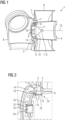
- In
fig. 1 , a detail of a wind turbine 1 is shown. The wind turbine 1 comprises a slidingbearing 2, which supports ahub 3 on a stationary shaft 4 of the wind turbine. The slidingbearing 2 comprises an annularrotatable part 5, which is connected to thehub 3 of the wind turbine 1. Furthermore, the slidingbearing 2 comprises an annularstationary part 6, which is connected to the stationary shaft 4 of the wind turbine 1. It is possible that thestationary part 6 of the bearing is attached to the shaft 4 or that it is fabricated one-piece with the shaft 4. - The sliding
bearing 2 further comprises a plurality of radially supporting sliding pads 7 and a plurality of axially supporting slidingpads 8. The radially supporting sliding pads 7 support therotatable part 5 of thebearing 2 on thestationary part 6 in a radial direction. Correspondingly, the radially supporting slidingpads 8 support therotatable part 5 of the sliding bearing in an axial direction on thestationary part 6. Between therotatable part 5 and the slidingpads 7, 8, a fluid film may be arranged allowing a sliding of therotatable part 5 on the slidingpads 7, 8 during operation of the wind turbine 1. - The
rotatable part 5 is arranged on an outer circumference of thestationary part 6. Thestationary part 6 comprises a plurality ofopenings 9, 10, wherein a plurality of first openings 9 each correspond to one of the radially supporting sliding pad 7, and a plurality ofsecond openings 10 each correspond to one of the axially supporting slidingpad 8. - As indicated by the
arrow 11, a radially supporting sliding pad 7 can be removed through the corresponding opening 9 in a radial direction towards the centre of thestationary part 6 of thebearing 2. Correspondingly, as indicated by the arrow 12, an axially supporting slidingpad 8 can be removed through thecorresponding opening 10 towards the centre of thestationary part 6. After removal, the slidingpads 7, 8 can then be transported out of thebearing 2, or the wind turbine 1, respectively, as indicated by thearrow 13. After removal of the slidingpad 7, 8, a replacement sliding pad can be inserted at a position of the removed slidingpad 7, 8 in a reverse movement. In particular, the replacement of the slidingpads 7, 8 may be performed manually and/or by usage of a lifting device manually installed prior to the replacement procedure in the vicinity of thebearing 2. - Since the
rotatable part 5 of the slidingbearing 2 is supported on thestationary part 6 via the slidingpads 7, 8, a slidingpad 7, 8 to be removed has to be unloaded from the weight of therotatable part 5, or the components of the wind turbine 1 connected to therotatable part 5, respectively. - It is also possible that the opening 9 is an axial opening of a radially cavity or a radially recess, in particular a radially inward recess in the outer circumference, of the stationary part housing the radially supporting sliding pad, so that the unloaded sliding pad may be removed in an axial direction from the recess axially towards one side of the bearing, in particular towards a side connected to the
hub 3 of the wind turbine 1, and/or in a radial direction towards the interior of thebearing 2. Also a tilted orientation of the opening 9 to the outer circumference of thestationary part 6 is possible so that the sliding pad 7 may be removed and/or replaced in a combined axial and radial movement. In a loaded state, the sliding pad 7 is fixed in a form-fit connection in the recess, wherein after unloading the sliding pad 7, a replacement of the sliding pad 7 becomes possible. - In a method for replacing a sliding
pad 7, 8 of a rotational slidingbearing 2 first a load of therotatable part 5 from the slidingpad 7, 8 is removed by releasing a force applied to the slidingpad 7, 8 and/or by applying a force to therotatable part 5. Afterwards, the unloaded slidingpad 7, 8 is removed in an axial and/or a radial direction and areplacement sliding pad 7, 8 is inserted. Then, therotatable part 5 is supported on thereplacement sliding pad 7, 8 by applying a force to thereplacement sliding pad 7, 8 and/or by removing the force applied to therotatable part 5. - Different ways of unloading at least one of the sliding
pads 7, 8 are described in relation to the following figures. The methods and sliding bearings covered byFig. 2 and3 are not part of the invention but alternatives examples. - In
fig. 2 , a slidingbearing 2 is shown. Due to the section view, a sliding pad 7 is discernible supporting therotatable part 5 on thestationary part 6. The radially supporting sliding pad 7 is engaged in anopening 10 of thestationary part 6 of thebearing 2. The radially supporting sliding pad 7 is in contact with therotatable part 5 of thebearing 2 inside a bearing case, wherein the bearing case is formed by therotatable part 5, thestationary part 6 and abearing cover 14. The bearing case covers in particular the contact area between the sliding pad 7 and therotatable part 5 as well as a fluid film in between the slidingpads 7, 8 and therotatable part 5 of thebearing 2. - The radially supporting sliding pad 7 is fixed to the
bearing 2 by a boltedconnection 24 comprising a plurality ofbolts 15 fixating acover plate 16 to thestationary part 6. By tightening the boltedconnection 24, hence by bolting theplate 16 to thestationary part 6 using thebolts 15, the radially supporting sliding pad 7 is pressed against therotatable part 5 of thebearing 2. In a mounted state of the radially supporting sliding pad 7, a force is acting on the sliding pad due to the weight of therotatable part 5 of thebearing 2 and/or due to the boltedconnection 24, respectively. - For removing the load of the
rotatable part 5 from the radially supporting sliding pad 7, the boltedconnection 24 can be released and theplate 16 can be removed. Afterwards, the sliding pad 7 can be removed from thebearing 2 in a radial direction towards the centre of thestationary part 6. After insertion of a replacement sliding pad 7 into theopening 10, theplate 16 can be fixed again to thestationary part 6 by tightening the boltedconnection 24. By tightening the boltedconnection 24, therotatable part 5 of thebearing 2 is supported again on the replaced sliding pad 7. When one of the radially supporting sliding pads 7 is unloaded, therotatable part 5 on the bearing is supported on the remainder of the radially supporting sliding pad 7 of the bearing and/or the axially supporting sliding pads 9 of thebearing 2, respectively. - In
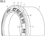
fig. 3 , a perspective view on the first embodiment of the slidingbearing 2 is shown. Besides a plurality of radially supporting sliding pads 7, thebearing 2 comprises a plurality of axially supporting slidingpads 8, which are fixed on the stationary part of the bearing each by a boltedconnection 17 comprising a plurality of bolts (not shown) and afixation member 18. Note that the bearingcover 14 is not shown, so that the axially supporting slidingpads 8 can be seen. Also the radially supporting sliding pads 7 and their respective fixatures are not shown. - The axially supporting sliding
pads 8 support therotatable part 5 of thebearing 2 to thestationary part 6 in the axial direction of thebearing 2. Also one of the axially supporting slidingpads 8 may be unloaded by untightening the boltedconnection 17 and by removing thefixation member 18. The axially supporting slidingpad 8 then may be removed in a radial direction, either in a radially outward direction from thebearing 2 or in a radially inward direction to the centre of thestationary part 6 through anopening 10 of thestationary part 6 of thebearing 2. Areplacement sliding pad 8 may then be inserted through theopening 10 in a reverse movement and therotatable part 5 may be supported on thereplacement sliding pad 8 by tightening of the boltedconnection 17 fixating the slidingpad 8 using thefixation member 18. - In
fig. 4 , a second embodiment of a slidingbearing 2 according to the invention is shown. Thebearing 2 comprises an actuator arrangement comprising a plurality ofactuators 19. Theactuators 19 are installed permanently inside the bearing case formed at least partly by the bearingcover 14, therotatable part 5 and thestationary part 6 housing the slidingpads 7, 8 and a fluid film of thebearing 2. Asactuator 19, a hydraulic jack is used. By theactuator 19, a displacement between thestationary part 6 and therotatable part 5 can be created. Theactuator 19 can therefore be connected for instance to a pump of thebearing 2 or of a wind turbine 1, which comprises thebearing 2, respectively. Also a connection of theactuator 19 to an external pump is possible. - To unload one or more radially supporting sliding pads 7, especially one or more radially supporting sliding pads 7 that are arranged circumferentially next to the depicted
actuator 19, a small displacement of approximately 1 mm of therotatable part 5 is sufficient to unload the sliding pad 7. The displacement is created by applying a force to therotatable part 5 using theactuator 19. After applying a force to therotatable part 5, hence after pushing therotatable part 5 slightly away from thestationary part 6, or the radially supporting sliding pad 7, respectively, the radially supporting sliding pad 7 is unloaded from therotatable part 5 and can be removed. Therefore, for instance acover plate 16 like previously described may be unattached to remove the radially sliding pad 7 through a corresponding opening 9. - In
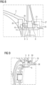
fig. 5 , a third embodiment of a slidingbearing 2 is shown. In this embodiment, the hydraulic jack used asactuator 19 is attached to an inner wall of thestationary part 6 and therefore outside of the bearing case of the slidingbearing 2. Theactuator 19 is fixed to thestationary part 6 and connected to therotatable part 5 by apiston 20 of theactuator 19. Thepiston 20 is arranged in anorifice 23 of thestationary part 6. Therefore, a displacement between therotatable part 5 and thestationary part 6 of thebearing 2 can be created by pushing away slightly therotatable part 5 from thestationary part 6 to unload at least one radially supporting sliding pad 7 in the vicinity of theactuator 19. Theactuator 19 is a radial actuator applying a force in the radial direction to therotatable part 5. - In
fig. 6 , a fourth embodiment of a slidingbearing 2 is shown. The slidingbearing 2 comprises a plurality ofactuators 19 arranged between aprotrusion 21 of thestationary part 6 and arotatable part 5 of thebearing 2. The protrusion protrudes from the outer circumference of thestationary part 6 adjacent to therotatable part 5. By theactuators 19, which may be each a hydraulic jack, an axial displacement between therotatable part 5 and thestationary part 6 of thebearing 2 can be created to unload at least one of the axial slidingpads 8 located next to theactuator 19. - The axially supporting sliding
pads 8 are arranged circumferentially displaced to theactuators 19. In analternative position 22, theactuators 19 may be arranged between therotatable part 5 of thebearing 2 and a protrusion of thestationary part 6, which is created by the bearingcover 14 attached to thestationary part 6. In particular, a plurality ofactuators 19 and a plurality of axially supporting slidingpads 8, especially a plurality of pairs of adjacently arranged slidingpads 8, are arranged alternatingly in circumferential direction. Theactuators 19 may be arranged in both positions, for instance alternatingly. In both positions, theactuators 19 are axial actuators applying an axial force to therotatable part 5. - After unloading one or more of the axial sliding
pads 8 using one or more of theactuators 19, the axial slidingpad 8 can be removed through theopening 10 in a radially inward direction of thestationary part 6. Afterwards, in a method for replacing the sliding pad, areplacement sliding pad 8 can be inserted through theopening 10 and therotatable part 5 can be supported again on thereplacement sliding pad 8 by removing the force applied to therotatable part 5 by theactuator 19. - Besides the positioning of the
actuator 19 inside the bearing case of thebearing 2, also positioning of at least oneactuator 19 to the outside of the bearing case is possible as described in the following embodiments. - In
fig. 7 , a fifth embodiment of a slidingbearing 2 according to the invention is shown. In this embodiment, theactuator 19 is arranged outside of the bearing case of thebearing 2. Theactuator 19 is fixed to abearing cover 14 of thebearing 2 and is therefore fixed to thestationary part 6 of thebearing 2. Theactuator 19 is connected to therotatable part 5 of the bearing by apiston 20 of theactuator 19 that is arranged in an orifice of the bearingcover 14, so that a displacement between therotatable part 5 and thestationary part 6 can be created using theactuator 19. By pushing therotatable part 5 away from the bearingcover 14, the one or more axially supporting slidingpads 8 circumferentially adjacent to theactuator 19 are unloaded and may be removed as previously described through theopening 10 of thestationary part 6 of thebearing 2. - Correspondingly, to remove an axially supporting sliding
pad 8 arranged on the opposing side of therotatable part 5, anactuator 19 may be attached in analternative position 32 to theprotrusion 21 of thestationary part 6 to allow for a displacement between therotatable part 5 and astationary part 6 of thebearing 2 in an opposing direction, so that the axially supporting slidingpad 8 between theprotrusion 21 and therotatable part 5 of thebearing 2 may be removed. - In
fig. 8 , a sixth embodiment of a slidingbearing 2 according to the invention is shown. In this embodiment, theactuator 19 is fixed to therotating part 5 of thebearing 2. Therefore, theactuator 19 may be fixed for instance to ahub 3 connected to therotating part 5 of the bearing using afixture 25. A displacement between therotatable part 5 and thestationary part 6 of thebearing 2 can be created using thepiston 20 of theactuator 19 so that at least one axially slidingpads 8 arranged between the bearingcover 14 and therotatable part 5 can be unloaded and removed as previously described. - Correspondingly, also an attachment of the
actuator 19 on an opposing side is possible as depicted by thealternative position 26, in which theactuator 19 is fixed to therotatable part 5 using afixture 27 to unload the axially supporting slidingpad 8 between therotatable part 5 and theprotrusion 21 of thestationary part 6. - In
fig. 9 , a seventh embodiment of a slidingbearing 2 according to the invention is shown. In this embodiment, a mechanical actuator comprising abase section 28 and a threadedbolt 29 is used as anactuator 19. The displacement between therotatable part 5 and astationary part 6 of thebearing 2 can be created by actuation of thebolt 29. Thebolt 29 of theactuator 19 can be actuated for instance manually or using an electric motor connector to thebolt 29. By moving thebolt 29 through a threaded portion of thebase section 28, a displacement between therotatable part 5 and thestationary part 6 of thebearing 2 can be created to unload one or more axially supporting slidingpads 8. During replacement of the slidingpad 8, therotatable part 5 is supported by the mechanical actuator. - Correspondingly to the previously described embodiments, such a mechanical actuator can be also used as an alternative to a hydraulic actuator in the respective positionings. It is also possible to use a mechanical actuator in addition to a hydraulic actuator, wherein the mechanical actuator is used to secure the
rotatable part 5 in its displaced position. - In
Fig. 10 , amilling tool 30 inserted in anopening 10 corresponding to an axially supporting slidingpad 8 is shown schematically. Themilling tool 30 comprises acover 31 corresponding to the shape of theopening 10 covering a surface trimming portion of themilling tool 30 from the interior of thebearing 2, so that for instance a surface treatment of a portion of thestationary part 6 and/or therotatable part 5 can be conducted without the risk of dirt entering the interior of thebearing 2, or the interior of the bearing case of thebearing 2, respectively. Correspondingly, amilling tool 30 with acover 31 corresponding to the shape of an opening 9 for replacement of a radially supporting sliding pad 7 may be used. - The step of surface treatment can be conducted in a method for replacing a sliding
pad 7, 8 after removing the slidingpad 7, 8 and prior to the insertion of a replacement sliding pad. The surface treatment may be conducted to account for damage and/or wear of therotatable part 5 and/or thestationary part 6. - In all embodiments, the actuator arrangement and/or the
bearing 2 may comprise a mechanical fixture device which fixes therotatable part 5 in its displaced position for securing it for instance in the event of a power loss of a hydraulic actuator or a mechanical actuator, respectively. It is in particular possible that abearing 2 comprises a plurality ofactuators 19 arranged in different positions combining two or more of the aforementioned embodiments. - Although the present invention has been described in detail with reference to the preferred embodiment, the present invention is not limited by the disclosed examples from which the skilled person is able to derive other variations without departing from the scope of the invention as defined by the appended claims.
Claims (14)
- Method for replacing a sliding pad (7, 8) of a rotational sliding bearing (2), wherein the bearing comprises a plurality of sliding pads (7, 8) each supporting an annular rotatable part (5) of the bearing (2) on a stationary part (6) of the bearing (2) in an axial direction and/or a radial direction, wherein the stationary part (6) is annular and the rotatable part (5) is arranged on a circumference of the stationary part (6), wherein the stationary part (6) comprises a plurality of axial and/or radial openings (9, 10) arranged circumferentially and/or axially displaced in the circumference of the stationary part (6), comprising the steps:- Removing a load of the rotatable part (5) from the sliding pad (7, 8) to be removed by applying a force to the rotatable part (5),- Removing the sliding pad (7, 8) in an axial and/or a radial direction through one of the openings (9, 10),- Inserting a replacement sliding pad (7, 8) through the opening (9, 10),- Supporting the rotatable part (5) on the replacement sliding pad (7, 8) by removing the force applied to the rotatable part (5).
- Method according to claim 1, characterized in that the stationary part (6) is annular, wherein the rotatable part (5) is arranged on an outer circumference of the stationary part (6), wherein the rotatable part (5) is supported on the stationary part (6) by the sliding pads (7, 8) in a radial and/or an axial direction, wherein the sliding pad (7, 8) is replaced from an interior of the stationary part (6) through an opening in the outer circumference of the stationary part (6).
- Method according to claim 1 or 2, characterized in that the sliding pad (7, 8) is fixed to the bearing (2) by a bolted connection (17, 24) applying a force to the sliding pad (7, 8), wherein the force is released by untightening of the bolted connection (17, 24), and/or by a form-fit connection, wherein the sliding pad is arranged in a cavity or a recess of the stationary part.
- Method according to one of the preceding claims, characterized in that the force is applied to the rotatable part (5) using an actuator arrangement comprising at least one actuator (19), in particular at least one mechanical actuator and/or at least one hydraulic actuator.
- Method according to claim 4, characterized in that an axial force on the rotatable part (5) of the bearing (2) for replacement of an axially supporting sliding pad (8) and/or a radial force for replacement of a radially supporting sliding pad (7) is applied by the actuator arrangement.
- Method according to one of the claims 4 or 5, characterized in that at least one actuator (19) of the actuator arrangement is detachably mounted to the bearing (2) prior to the removal of the load from the sliding pad (7, 8) to be replaced and/or that at least one actuator (19) of the actuator arrangement is permanently mounted to the bearing (2).
- Method according to one of the preceding claims, characterized in that prior to the insertion of the replacement sliding pad (7, 8), a surface treatment of a surface of the stationary part (6) and/or a surface of the rotatable part (5) is conducted.
- Sliding bearing comprising an annular rotatable part (5), a stationary part (6) and a plurality of sliding pads (7, 8), wherein the stationary part (6) is annular and the rotatable part (5) is arranged on a circumference of the stationary part (6), wherein the rotatable part (5) is supported on the stationary part (6) by the sliding pads (7, 8) in a radial and/or an axial direction, wherein the stationary part (6) comprises a plurality of axial and/or radial openings (9, 10) arranged circumferentially and/or axially displaced in the circumference of the stationary part (6), wherein the sliding pads (7, 8) are removable and/or insertable through the openings (9, 10), characterized in that the bearing (2) comprises an actuator arrangement with one or more actuators (19) mounted to the sliding bearing,
wherein the actuator arrangement is adapted for removing a load of the rotatable part (5) from at least one of the sliding pads (7, 8) to be removed. - Sliding bearing according to claim 8, characterized in that the actuator arrangement comprises at least one mechanical actuator and/or at least one hydraulic actuator.
- Sliding bearing according to claim 9, characterized in that the at least one actuator (19) of the actuator arrangement is arranged circumferentially displaced from the sliding pads (7, 8).
- Sliding bearing according to claim 9 or 10, characterized in that the actuator arrangement comprises at least one radial actuator (19) arranged at least partly in between the stationary part (6) and the rotatable part (5) for applying a radial force on the rotatable part (5) and/or at least one axial actuator (19) arranged at least partly between the rotatable part (5) and a protrusion (21) on the circumference of the stationary part (6) for applying an axial force on the rotatable part (5).
- Sliding bearing according to claim 9 to 11, characterized in that the bearing (2) comprises a bearing case, wherein the actuator arrangement is arranged inside the bearing case.
- Sliding bearing according to claim 9 to 12, characterized in that the one or more actuators (19) of the actuator arrangement each are fixed to the stationary part (6) or the rotatable part (5) of the bearing.
- Wind turbine comprising a sliding bearing (2) according to one of the claims 9 to 13.
Applications Claiming Priority (2)
| Application Number | Priority Date | Filing Date | Title |
|---|---|---|---|
| EP20171732.9A EP3904711A1 (en) | 2020-04-28 | 2020-04-28 | Method for replacing a sliding pad of a rotational sliding bearing, sliding bearing and wind turbine |
| PCT/EP2021/060929 WO2021219602A1 (en) | 2020-04-28 | 2021-04-27 | Method for replacing a sliding pad of a rotational sliding bearing, sliding bearing and wind turbine |
Publications (2)
| Publication Number | Publication Date |
|---|---|
| EP4118352A1 EP4118352A1 (en) | 2023-01-18 |
| EP4118352B1 true EP4118352B1 (en) | 2023-12-27 |
Family
ID=70475974
Family Applications (2)
| Application Number | Title | Priority Date | Filing Date |
|---|---|---|---|
| EP20171732.9A Withdrawn EP3904711A1 (en) | 2020-04-28 | 2020-04-28 | Method for replacing a sliding pad of a rotational sliding bearing, sliding bearing and wind turbine |
| EP21721100.2A Active EP4118352B1 (en) | 2020-04-28 | 2021-04-27 | Method for replacing a sliding pad of a rotational sliding bearing, sliding bearing and wind turbine |
Family Applications Before (1)
| Application Number | Title | Priority Date | Filing Date |
|---|---|---|---|
| EP20171732.9A Withdrawn EP3904711A1 (en) | 2020-04-28 | 2020-04-28 | Method for replacing a sliding pad of a rotational sliding bearing, sliding bearing and wind turbine |
Country Status (7)
| Country | Link |
|---|---|
| US (1) | US20230341000A1 (en) |
| EP (2) | EP3904711A1 (en) |
| JP (1) | JP2023524226A (en) |
| KR (1) | KR20220158075A (en) |
| CN (1) | CN115427698A (en) |
| DK (1) | DK4118352T3 (en) |
| WO (1) | WO2021219602A1 (en) |
Families Citing this family (3)
| Publication number | Priority date | Publication date | Assignee | Title |
|---|---|---|---|---|
| DK4043743T3 (en) * | 2021-02-12 | 2023-11-20 | Siemens Gamesa Renewable Energy As | BEARING FOR A WINDMILL, WINDMILL COMPRISING A BEARING, AND METHOD OF MAKING A BEARING |
| EP4343149A1 (en) | 2022-09-21 | 2024-03-27 | Siemens Gamesa Renewable Energy A/S | Fluid film bearing comprising bearing pads and method of replacing bearing pads |
| EP4343148A1 (en) | 2022-09-21 | 2024-03-27 | Siemens Gamesa Renewable Energy A/S | Fluid film bearing comprising bearing pads and method of replacing bearing pads |
Family Cites Families (7)
| Publication number | Priority date | Publication date | Assignee | Title |
|---|---|---|---|---|
| DE9207013U1 (en) * | 1992-05-23 | 1992-07-23 | A. Friedr. Flender Ag, 4290 Bocholt, De | |
| DE102009049769A1 (en) * | 2009-10-16 | 2011-04-21 | Suzlon Energy Gmbh | Bearing arrangement for a wind turbine |
| EP2711568B1 (en) * | 2012-09-24 | 2018-05-30 | Siemens Aktiengesellschaft | Sliding bearing and method to perform service at the sliding bearing |
| EP3219984B1 (en) * | 2016-03-14 | 2019-01-02 | Siemens Aktiengesellschaft | Sliding bearing arrangement for a wind turbine |
| DK179077B1 (en) * | 2016-03-23 | 2017-10-09 | Envision Energy Denmark Aps | Wind turbine comprising a yaw bearing system |
| EP3460272B1 (en) | 2017-09-20 | 2020-04-01 | Siemens Gamesa Renewable Energy A/S | Method for changing a bearing component and tool device for changing a bearing component |
| EP3594495B1 (en) * | 2018-07-10 | 2022-09-07 | Siemens Gamesa Renewable Energy A/S | Wind turbine yaw bearing |
-
2020
- 2020-04-28 EP EP20171732.9A patent/EP3904711A1/en not_active Withdrawn
-
2021
- 2021-04-27 JP JP2022565814A patent/JP2023524226A/en active Pending
- 2021-04-27 CN CN202180031882.6A patent/CN115427698A/en active Pending
- 2021-04-27 US US17/919,555 patent/US20230341000A1/en active Pending
- 2021-04-27 WO PCT/EP2021/060929 patent/WO2021219602A1/en unknown
- 2021-04-27 KR KR1020227037514A patent/KR20220158075A/en unknown
- 2021-04-27 DK DK21721100.2T patent/DK4118352T3/en active
- 2021-04-27 EP EP21721100.2A patent/EP4118352B1/en active Active
Also Published As
| Publication number | Publication date |
|---|---|
| US20230341000A1 (en) | 2023-10-26 |
| JP2023524226A (en) | 2023-06-09 |
| DK4118352T3 (en) | 2024-03-04 |
| EP3904711A1 (en) | 2021-11-03 |
| CN115427698A (en) | 2022-12-02 |
| WO2021219602A1 (en) | 2021-11-04 |
| KR20220158075A (en) | 2022-11-29 |
| EP4118352A1 (en) | 2023-01-18 |
Similar Documents
| Publication | Publication Date | Title |
|---|---|---|
| EP4118352B1 (en) | Method for replacing a sliding pad of a rotational sliding bearing, sliding bearing and wind turbine | |
| US11603824B2 (en) | Uptower crane and rotor lock for wind turbine component replacement | |
| EP2711568B1 (en) | Sliding bearing and method to perform service at the sliding bearing | |
| EP2711569B1 (en) | Sliding bearing and method to perform service at a sliding bearing | |
| EP2148090B1 (en) | Locking assembly for the rotor of a wind power turbine | |
| KR101234378B1 (en) | Wind turbine generator and maintenance method thereof | |
| EP3460272B1 (en) | Method for changing a bearing component and tool device for changing a bearing component | |
| EP3009617B1 (en) | Lifting tool for rotary shaft and lifting method for rotary shaft | |
| US20120145976A1 (en) | Casing section lift and transport system | |
| EP2690256A2 (en) | Method and system for assembling and disassembling shells of turbomachines | |
| CN110701007B (en) | Wind turbine | |
| EP4343148A1 (en) | Fluid film bearing comprising bearing pads and method of replacing bearing pads | |
| EP4343149A1 (en) | Fluid film bearing comprising bearing pads and method of replacing bearing pads | |
| CN115398082A (en) | Steam turbine maintenance method and steam turbine | |
| WO2023072354A1 (en) | Method for performing maintenance on a yaw system of a wind turbine | |
| KR100454218B1 (en) | Upper rigid coupling cap screw ejector for reactor coolant pump |
Legal Events
| Date | Code | Title | Description |
|---|---|---|---|
| STAA | Information on the status of an ep patent application or granted ep patent |
Free format text: STATUS: UNKNOWN |
|
| STAA | Information on the status of an ep patent application or granted ep patent |
Free format text: STATUS: THE INTERNATIONAL PUBLICATION HAS BEEN MADE |
|
| PUAI | Public reference made under article 153(3) epc to a published international application that has entered the european phase |
Free format text: ORIGINAL CODE: 0009012 |
|
| STAA | Information on the status of an ep patent application or granted ep patent |
Free format text: STATUS: REQUEST FOR EXAMINATION WAS MADE |
|
| 17P | Request for examination filed |
Effective date: 20221013 |
|
| AK | Designated contracting states |
Kind code of ref document: A1 Designated state(s): AL AT BE BG CH CY CZ DE DK EE ES FI FR GB GR HR HU IE IS IT LI LT LU LV MC MK MT NL NO PL PT RO RS SE SI SK SM TR |
|
| DAV | Request for validation of the european patent (deleted) | ||
| DAX | Request for extension of the european patent (deleted) | ||
| GRAP | Despatch of communication of intention to grant a patent |
Free format text: ORIGINAL CODE: EPIDOSNIGR1 |
|
| STAA | Information on the status of an ep patent application or granted ep patent |
Free format text: STATUS: GRANT OF PATENT IS INTENDED |
|
| INTG | Intention to grant announced |
Effective date: 20230808 |
|
| GRAS | Grant fee paid |
Free format text: ORIGINAL CODE: EPIDOSNIGR3 |
|
| GRAA | (expected) grant |
Free format text: ORIGINAL CODE: 0009210 |
|
| STAA | Information on the status of an ep patent application or granted ep patent |
Free format text: STATUS: THE PATENT HAS BEEN GRANTED |
|
| AK | Designated contracting states |
Kind code of ref document: B1 Designated state(s): AL AT BE BG CH CY CZ DE DK EE ES FI FR GB GR HR HU IE IS IT LI LT LU LV MC MK MT NL NO PL PT RO RS SE SI SK SM TR |
|
| REG | Reference to a national code |
Ref country code: GB Ref legal event code: FG4D |
|
| REG | Reference to a national code |
Ref country code: CH Ref legal event code: EP |
|
| REG | Reference to a national code |
Ref country code: DE Ref legal event code: R096 Ref document number: 602021008129 Country of ref document: DE |
|
| REG | Reference to a national code |
Ref country code: IE Ref legal event code: FG4D |
|
| REG | Reference to a national code |
Ref country code: DK Ref legal event code: T3 Effective date: 20240229 |
|
| REG | Reference to a national code |
Ref country code: NL Ref legal event code: FP |
|
| PG25 | Lapsed in a contracting state [announced via postgrant information from national office to epo] |
Ref country code: GR Free format text: LAPSE BECAUSE OF FAILURE TO SUBMIT A TRANSLATION OF THE DESCRIPTION OR TO PAY THE FEE WITHIN THE PRESCRIBED TIME-LIMIT Effective date: 20240328 |
|
| REG | Reference to a national code |
Ref country code: LT Ref legal event code: MG9D |
|
| PG25 | Lapsed in a contracting state [announced via postgrant information from national office to epo] |
Ref country code: LT Free format text: LAPSE BECAUSE OF FAILURE TO SUBMIT A TRANSLATION OF THE DESCRIPTION OR TO PAY THE FEE WITHIN THE PRESCRIBED TIME-LIMIT Effective date: 20231227 |