EP4117353A1 - Method for determining timing advance, and communication apparatus - Google Patents
Method for determining timing advance, and communication apparatus Download PDFInfo
- Publication number
- EP4117353A1 EP4117353A1 EP21779991.5A EP21779991A EP4117353A1 EP 4117353 A1 EP4117353 A1 EP 4117353A1 EP 21779991 A EP21779991 A EP 21779991A EP 4117353 A1 EP4117353 A1 EP 4117353A1
- Authority
- EP
- European Patent Office
- Prior art keywords
- period
- moment
- signal
- indication information
- terminal
- Prior art date
- Legal status (The legal status is an assumption and is not a legal conclusion. Google has not performed a legal analysis and makes no representation as to the accuracy of the status listed.)
- Pending
Links
Images


Classifications
-
- H—ELECTRICITY
- H04—ELECTRIC COMMUNICATION TECHNIQUE
- H04W—WIRELESS COMMUNICATION NETWORKS
- H04W56/00—Synchronisation arrangements
- H04W56/004—Synchronisation arrangements compensating for timing error of reception due to propagation delay
-
- H—ELECTRICITY
- H04—ELECTRIC COMMUNICATION TECHNIQUE
- H04W—WIRELESS COMMUNICATION NETWORKS
- H04W56/00—Synchronisation arrangements
- H04W56/004—Synchronisation arrangements compensating for timing error of reception due to propagation delay
- H04W56/0045—Synchronisation arrangements compensating for timing error of reception due to propagation delay compensating for timing error by altering transmission time
-
- H—ELECTRICITY
- H04—ELECTRIC COMMUNICATION TECHNIQUE
- H04B—TRANSMISSION
- H04B7/00—Radio transmission systems, i.e. using radiation field
- H04B7/14—Relay systems
- H04B7/15—Active relay systems
- H04B7/185—Space-based or airborne stations; Stations for satellite systems
- H04B7/1851—Systems using a satellite or space-based relay
- H04B7/18513—Transmission in a satellite or space-based system
-
- H—ELECTRICITY
- H04—ELECTRIC COMMUNICATION TECHNIQUE
- H04W—WIRELESS COMMUNICATION NETWORKS
- H04W56/00—Synchronisation arrangements
- H04W56/003—Arrangements to increase tolerance to errors in transmission or reception timing
-
- H—ELECTRICITY
- H04—ELECTRIC COMMUNICATION TECHNIQUE
- H04W—WIRELESS COMMUNICATION NETWORKS
- H04W56/00—Synchronisation arrangements
- H04W56/004—Synchronisation arrangements compensating for timing error of reception due to propagation delay
- H04W56/005—Synchronisation arrangements compensating for timing error of reception due to propagation delay compensating for timing error by adjustment in the receiver
Definitions
- Embodiments of this application relate to the field of communication technologies, and in particular, to a method for determining a timing advance and a communication apparatus.
- NTN communication includes satellite communication, air-to-ground (air to ground, ATG) communication, and the like.
- ATG air to ground
- NTN communication has obviously different transmission features.
- NTN communication usually has a larger transmission delay.
- round-trip time of geostationary earth orbit (geostationary earth orbit, GEO) satellite communication (regeneration mode) is 238 ms to 270 ms.
- Round-trip time of low earth orbit (LEO) satellite communication (orbit altitude 1200 km, regeneration mode) is 8 ms to 20 ms.
- maximum round-trip time may also reach 1 ms.
- a maximum timing advance (timing advance, TA) range indicated in a random access response (random access response, RAR) is 0 ms to 2 ms.
- timing advance, TA timing advance
- RAR random access response
- Embodiments of this application provide a method for determining a timing advance and a communication apparatus, to resolve a problem that a method for indicating a TA in an RAR is insufficient to indicate round-trip time length in an NTN communication scenario.
- a method for determining a timing advance is provided.
- the method may be applied to a terminal.
- the method may be applied to but is not limited to a scenario of communicating with an NTN.
- the method is implemented by using the following steps: receiving a downlink signal from the network device, determining a first reference moment of a signal period of the downlink signal, determining a timing advance based on the first reference moment and a second reference moment, and sending an uplink signal to the network device based on the timing advance.
- the signal period is a period in which the network device sends the downlink signal, and the terminal may receive the downlink signal at some or all moments in the signal period.
- the second reference moment is determined based on a first time interval.
- the first time interval is an interval between the first reference moment and a start moment of a first period.
- the first reference moment is located in the first period.
- a period is a duration distributed at an equal interval on a time axis.
- the first period is one of durations on the time axis.
- the terminal can determine the timing advance based on the first reference moment, the second reference moment, and the period.
- the network device does not need to indicate a value of the TA by using signaling. This can effectively reduce signaling overheads for determining the TA on a terminal side.
- a value of the TA in a long range may be determined by using the method in this embodiment of this application, to avoid a problem that a method for indicating a TA in an RAR is insufficient to indicate round-trip time in the NTN scenario.
- a timing range in which a random access preamble sent by the terminal arrives at the network device is large. According to the method in this embodiment of this application, a length of a cyclic prefix of the random access preamble can be reduced.
- the first reference moment is a start receiving moment of the signal period
- the second reference moment is a start sending moment of the signal period.
- the start receiving moment and the start sending moment of the signal period are used as reference moments, so that complexity of calculating the TA on the terminal side can be reduced.
- the start sending moment is located in a second period, and the second period is a duration on the time axis.
- the method includes: determining whether the start receiving moment and the start sending moment are in a same period; and determining the start sending moment based on a determining result. It can be determined, by determining whether the start receiving moment and the start sending moment are in the same period, whether the start sending moment is in the period of the start receiving moment or in a period preceding the period including the start receiving moment. Because a start moment of the period including the start receiving moment can be obtained by the terminal through measurement, the start sending moment can be further calculated, to determine a value of the TA.
- An interval between the start sending moment and a start moment of a second period is a second time interval. If the first time interval is not less than the second time interval, the start receiving moment and the start sending moment are in a same period, and the second period and the first period are a same period. Alternatively, if the first time interval is less than the second time interval, the start receiving moment and the start sending moment are not in a same period, and the first period is a period following the second period.
- the start sending moment is a moment obtained by postponing the start moment of the first period by the second time interval.
- the start sending moment is a moment obtained by postponing the start moment of the second period by the second time interval.
- the start moment of the second period is a moment obtained by advancing the start moment of the first period by a period.
- This method is applicable when the period is greater than a maximum one-way delay.
- the following optional manner 2 is not only applicable to a case in which the period is greater than the maximum one-way delay, but also applicable to a case in which the period is less than or equal to the maximum one-way delay.
- the method includes: receiving first indication information from the network device.
- the first indication information indicates an attribute of a duration sequence number of the second period on the time axis, and the attribute includes an odd number or an even number.
- the method includes determining, based on the first indication information, whether attributes of duration sequence numbers of the first period and the second period on the time axis are the same. If the attributes of the duration sequence numbers of the first period and the second period on the time axis are the same, it is determined that the start receiving moment and the start sending moment are in the same period, and the second period and the first period are a same period. If the attributes of the duration sequence numbers of the first period and the second period on the time axis are not the same, it is determined that the start receiving moment and the start sending moment are not in the same period, and the first period is a period following the second period.
- the method includes receiving second indication information from the network device.
- the second indication information indicates a reference signal period.
- a difference between a start sending moment of the reference signal period and a start moment of a third period is a first fixed value.
- the first fixed value may be any value greater than or equal to 0.
- the start sending moment of the reference signal period is located in the third period.
- the method includes: determining the second time interval based on a distance between a start moment of the signal period of the downlink signal and the start sending moment of the reference signal period.
- the second time interval is obtained by adding the distance and the first fixed value and then performing a modulo operation on one period.
- the first fixed value may also be less than 0.
- the second time interval is a value obtained by subtracting the first fixed value from the distance and then performing a modulo operation on one period.
- the terminal may calculate the second time interval by indicating the first fixed value, thereby further reducing signaling overheads.
- the method includes: receiving third indication information from the network device, where the third indication information indicates the second time interval.
- the second time interval is a time value or a quantity.
- the quantity indicates a quantity of time units included in the second time interval.
- the period is divided into a plurality of time units. This design provides a more flexible manner of indicating the second time interval.
- the determining the timing advance based on the start receiving moment and the start sending moment is specifically implemented in any one of the following manners:
- the timing advance is a difference multiplied by two, and the difference is a difference between the start receiving moment and the start sending moment; or the timing advance is a sum or a difference between a difference multiplied by 2 and an adjustment value, and the adjustment value is related to a signal processing time and/or relative movement between the network device and the terminal.
- the signal period may be a modification period of system information.
- the terminal obtains the signal period, so that signaling overheads of sending the signal period configuration by the network device to the terminal can be reduced, and power consumption of receiving signaling by the terminal is also reduced.
- a method for determining a timing advance is provided.
- the method may be performed by a terminal.
- the method is implemented by using the following steps: receiving a downlink signal from the network device, determining a first reference moment of a signal period of the downlink signal, determining a timing advance based on the first reference moment and a second reference moment, and sending an uplink signal to the network device based on the timing advance.
- the signal period is a period in which the network device sends a downlink signal.
- a length of a period is M times a length of the signal period. M is a value greater than 0.
- M may be a value greater than 1, and the length of the period is greater than the length of the signal period. Alternatively, M may be a value less than 1, and the length of the period is less than the length of the signal period. It is set that the second reference moment is aligned with or differs from a start moment of the period by a fixed value. Alternatively, it is set that the second reference moment is aligned with or differs from any specified moment of the period by a fixed value.
- the fixed value may be a value greater than 0, less than 0, or equal to 0.
- a start sending moment of a period at which the network device sends a signal may be deduced based on time of the downlink signal, to further determine the timing advance.
- the network device does not need to indicate a value of the TA by using signaling, so that signaling overheads for determining the TA on a terminal side can be effectively reduced.
- a value of the TA in a long range may be determined by using the method in this embodiment of this application, to avoid a problem that a method for indicating a TA in an RAR is insufficient to indicate round-trip time in the NTN scenario.
- a timing range in which a random access preamble sent by the terminal arrives at the network device is large.
- a length of a cyclic prefix of the random access preamble can be reduced.
- the first reference moment is a start receiving moment of the signal period
- the second reference moment is a start sending moment of the signal period.
- the start receiving moment and the start sending moment of the signal period are used as reference moments, so that complexity of calculating the TA on the terminal side can be reduced.
- the terminal may determine, based on the first reference moment, a start moment of a first period in which the first reference moment is located. The terminal determines, based on the start moment of the first period and a second fixed value, the start sending moment of the signal period.
- the terminal After determining the first reference moment, the terminal determines which 1/M of the first period the first reference moment is in, to determine the start moment of the first period. The terminal determines the start sending moment of the signal period based on the start moment of the first period, a 1/M th 1/M of the first reference moment, and the second fixed value.
- the second fixed value is equal to 0, and the start sending moment is the start moment of the period.
- the second fixed value is less than 0, and the start sending moment obtained by advancing the start moment of the period by the fixed value.
- the second fixed value is greater than 0, and the start sending moment is obtained by postponing the start moment of the period by the fixed value.
- the method includes receiving indication information from the network device, where the indication information indicates the length of the signal period.
- a specific value of the length of the signal period may be indicated, or one bit may be used to indicate whether a first value or a second value is selected for the signal period.
- the first value is a newly defined value
- the second value is a value of a regular modification period of system information.
- the length of the signal period is a positive integer multiple of 250 ms.
- the determining the timing advance based on the start receiving moment and the start sending moment is specifically implemented in any one of the following manners:
- the timing advance is a difference multiplied by two, and the difference is a difference between the start receiving moment and the start sending moment; or the timing advance is a sum or a difference between a difference multiplied by 2 and an adjustment value, and the adjustment value is related to a signal processing time and/or relative movement between the network device and the terminal.
- the signal period may be a modification period of system information.
- the terminal obtains the signal period, so that signaling overheads of sending the signal period configuration by the network device to the terminal can be reduced, and power consumption of receiving signaling by the terminal is also reduced.
- a method for determining a timing advance may be applied to a network device.
- the method may be applied to but is not limited to a scenario of communicating with an NTN.
- the method is implemented by using the following steps: sending indication information to a terminal, where the indication information determines, for the terminal, a timing advance for sending an uplink signal; and receiving the uplink signal from the terminal.
- the indication information indicates information about a time interval.
- the time interval is an interval between a reference moment and a start moment of a period.
- the reference moment is located in the period.
- the period is one of durations distributed at equal intervals on a time axis.
- the indication information indicates an attribute of a duration sequence number of the period on the time axis.
- the attribute includes an odd number or an even number.
- the indication information indicates a reference signal period.
- a difference between a start moment of the reference signal period and a start moment of a period in which the start moment is located is a fixed value.
- the fixed value is greater than 0, less than 0, or equal to 0.
- some information related to the period may be indicated to the terminal by using indication information, so that the terminal determines the timing advance based on the indication information.
- the network device does not need to indicate a value of the TA by using signaling, so that signaling overheads for determining the TA on a terminal side can be effectively reduced.
- a value of the TA in a long range may be determined by using the method in this embodiment of this application, to avoid a problem that a method for indicating a TA in an RAR is insufficient to indicate round-trip time in the NTN scenario.
- a timing range in which a random access preamble sent by the terminal arrives at the network device is large. According to the method in this embodiment of this application, a length of a cyclic prefix of the random access preamble can be reduced.
- the method includes periodically sending a downlink signal based on a signal period.
- a start sending moment of the signal period is the reference moment, or the start sending moment of the signal period is a moment determined by combining the reference moment and a delay compensation value.
- a delay compensation value may be used to reduce round-trip time.
- first indication information when the first indication information indicates the information about the time interval, first indication information is a time value or a quantity.
- the quantity indicates a quantity of time units included in the time interval.
- the period is divided into a plurality of time units. This design provides a more flexible manner of indicating the time interval.
- a method for determining a timing advance may be applied to a network device.
- the method may be applied to but is not limited to a scenario of communicating with an NTN.
- the method is implemented by using the following steps: sending a downlink signal based on a signal period.
- a length of a period is M times a length of the signal period.
- M is a value greater than 0, and the period is a duration distributed at an equal interval on a time axis.
- M may be a value greater than 1, and the length of the period is greater than the length of the signal period.
- M may be a value less than 1, and the length of the period is less than the length of the signal period.
- a difference between a start moment of the signal period and a start moment of the period is a fixed value.
- the fixed value is greater than 0, less than 0, or equal to 0.
- the fixed value is used by a terminal to determine a timing advance for sending an uplink signal. The method includes: receiving the uplink signal from the terminal.
- a start sending moment of a period at which the network device sends a signal may be deduced based on time of the downlink signal, to further determine the timing advance.
- the network device does not need to indicate a value of the TA by using signaling, so that signaling overheads for determining the TA on a terminal side can be effectively reduced.
- a value of the TA in a long range may be determined by using the method in this embodiment of this application, to avoid a problem that a method for indicating a TA in an RAR is insufficient to indicate round-trip time in the NTN scenario.
- a timing range in which a random access preamble sent by the terminal arrives at the network device is large.
- a length of a cyclic prefix of the random access preamble can be reduced.
- the fixed value is equal to 0, and the start sending moment is the start moment of the period.
- the fixed value is less than 0, and the start sending moment obtained by advancing the start moment of the period by the fixed value.
- the fixed value is greater than 0, and the start sending moment is obtained by postponing the start moment of the period by the fixed value.
- the method includes sending indication information to the terminal, where the indication information indicates the length of the signal period.
- a specific value of the length of the signal period may be indicated, or one bit may be used to indicate whether a first value or a second value is selected for the signal period.
- the first value is a newly defined value
- the second value is a value of a regular modification period of system information.
- the signal period may be a modification period of system information.
- the terminal obtains the signal period, so that signaling overheads of sending the signal period configuration by the network device to the terminal can be reduced, and power consumption of receiving signaling by the terminal is also reduced.
- the length of the signal period is a positive integer multiple of 250 ms.
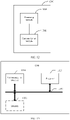
- a communication apparatus may be a terminal device, may be an apparatus (for example, a chip, a chip system, or a circuit) in a terminal device, or may be an apparatus that can be used with a terminal device.
- the apparatus has a function of implementing the method in any one of the first aspect or the possible designs of the first aspect.
- the function may be implemented by hardware, or may be implemented by hardware executing corresponding software.
- the hardware or the software includes one or more modules corresponding to the foregoing function.
- the apparatus may include a communication module and a processing module. For example:
- the communication module is configured to receive a downlink signal from a network device.
- the processing module is configured to: determine a first reference moment of a signal period of the downlink signal, and determine a timing advance based on the first reference moment and a second reference moment.
- the communication module is further configured to send an uplink signal to the network device based on the timing advance.
- the signal period is a period in which the network device sends the downlink signal, and the terminal may receive the downlink signal at some or all moments in the signal period.
- the second reference moment is determined based on a first time interval.
- the first time interval is an interval between the first reference moment and a start moment of a first period.
- the first reference moment is located in the first period.
- a period is a duration distributed at an equal interval on a time axis.
- the first period is one of durations on the time axis.
- the first reference moment is a start receiving moment of the signal period
- the second reference moment is a start sending moment of the signal period.
- the start receiving moment and the start sending moment of the signal period are used as reference moments, so that complexity of calculating the TA on the terminal side can be reduced.
- the start sending moment is located in a second period, and the second period is a duration on the time axis.
- the processing module is further configured to: determine whether the start receiving moment and the start sending moment are in a same period; and determine the start sending moment based on a determining result. It can be determined, by determining whether the start receiving moment and the start sending moment are in the same period, whether the start sending moment is in the period of the start receiving moment or in a period preceding the period including the start receiving moment. Because a start moment of the period including the start receiving moment can be obtained by the terminal through measurement, the start sending moment can be further calculated, to determine a value of the TA.
- Determining whether the start receiving moment and the start sending moment are in the same period may be specifically implemented by the processing module in the following several optional manners.
- An interval between the start sending moment and a start moment of a second period is a second time interval.
- the processing module is configured to: if the first time interval is not less than the second time interval, determine that the start receiving moment and the start sending moment are in a same period, and the second period and the first period are a same period.
- the processing module is configured to: if the first time interval is less than the second time interval, determine that the start receiving moment and the start sending moment are not in a same period, and the first period is a period following the second period.
- the start sending moment is a moment obtained by postponing the start moment of the first period by the second time interval.
- the start sending moment is a moment obtained by postponing the start moment of the second period by the second time interval.
- the start moment of the second period is a moment obtained by advancing the start moment of the first period by a period.
- This method is applicable when the period is greater than a maximum one-way delay.
- the following optional manner 2 is not only applicable to a case in which the period is greater than the maximum one-way delay, but also applicable to a case in which the period is less than or equal to the maximum one-way delay.
- the communication module is configured to receive first indication information from the network device.
- the first indication information indicates an attribute of a duration sequence number of the second period on the time axis, and the attribute includes an odd number or an even number.
- the communication module is configured to determine, based on the first indication information, whether attributes of duration sequence numbers of the first period and the second period on the time axis are the same. If the attributes of the duration sequence numbers of the first period and the second period on the time axis are the same, it is determined that the start receiving moment and the start sending moment are in the same period, and the second period and the first period are a same period. If the attributes of the duration sequence numbers of the first period and the second period on the time axis are not the same, it is determined that the start receiving moment and the start sending moment are not in the same period, and the first period is a period following the second period.
- the communication module is configured to receive second indication information from the network device.
- the second indication information indicates a reference signal period.
- a difference between a start sending moment of the reference signal period and a start moment of a third period is a first fixed value.
- the first fixed value may be any value greater than or equal to 0.
- the start sending moment of the reference signal period is located in the third period.
- the communication module is configured to determine the second time interval based on a distance between a start moment of the signal period of the downlink signal and the start sending moment of the reference signal period.
- the second time interval is obtained by adding the distance and the first fixed value and then performing a modulo operation on one period.
- the first fixed value may also be less than 0.
- the second time interval is a value obtained by subtracting the first fixed value from the distance and then performing a modulo operation on one period.
- the terminal may calculate the second time interval by indicating the first fixed value, thereby further reducing signaling overheads.
- the communication module is configured to receive third indication information from the network device.
- the third indication information indicates the second time interval.
- the second time interval is a time value or a quantity.
- the quantity indicates a quantity of time units included in the second time interval.
- the period is divided into a plurality of time units. This design provides a more flexible manner of indicating the second time interval.
- the processing module determines the timing advance based on the start receiving moment and the start sending moment is specifically implemented in any one of the following manners:
- the timing advance is a difference multiplied by two, and the difference is a difference between the start receiving moment and the start sending moment; or the timing advance is a sum or a difference between a difference multiplied by 2 and an adjustment value, and the adjustment value is related to a signal processing time and/or relative movement between the network device and the terminal.
- the signal period may be a modification period of system information.
- the terminal obtains the signal period, so that signaling overheads of sending the signal period configuration by the network device to the terminal can be reduced, and power consumption of receiving signaling by the terminal is also reduced.
- a communication apparatus may be a terminal device, may be an apparatus (for example, a chip, a chip system, or a circuit) in a terminal device, or may be an apparatus that can be used with a terminal device.
- the apparatus may include modules that are in one-to-one correspondence with the methods/operations/steps/actions described in the second aspect.
- the modules may be implemented by using a hardware circuit, software, or a combination of the hardware circuit and the software.
- the apparatus may include a processing module and a communication module.
- the processing module is configured to invoke the communication module to perform a receiving function and/or a sending function. For example,
- the communication module is configured to receive a downlink signal from a network device.
- the processing module is configured to: determine a first reference moment of a signal period of the downlink signal, and determine a timing advance based on the first reference moment and a second reference moment.
- the communication module is further configured to send an uplink signal to the network device based on the timing advance.
- the signal period is a period in which the network device sends a downlink signal.
- a length of a period is M times a length of the signal period. M is a value greater than 0.
- M may be a value greater than 1, and the length of the period is greater than the length of the signal period. Alternatively, M may be a value less than 1, and the length of the period is less than the length of the signal period. It is set that the second reference moment is aligned with or differs from a start moment of the period by a fixed value. Alternatively, it is set that the second reference moment is aligned with or differs from any specified moment of the period by a fixed value.
- the fixed value may be a value greater than 0, less than 0, or equal to 0.
- the first reference moment is a start receiving moment of the signal period
- the second reference moment is a start sending moment of the signal period.
- the start receiving moment and the start sending moment of the signal period are used as reference moments, so that complexity of calculating the TA on the terminal side can be reduced.
- the processing module is configured to: determine, based on the first reference moment, a start moment of a first period in which the first reference moment is located, and determine, based on the start moment of the first period and a second fixed value, the start sending moment of the signal period.
- the processing module is configured to determine which 1/M of the first period the first reference moment is in, to determine the start moment of the first period.
- the terminal determines the start sending moment of the signal period based on the start moment of the first period, a 1/M th 1/M of the first reference moment, and the second fixed value.
- the second fixed value is equal to 0, and the start sending moment is the start moment of the period.
- the second fixed value is less than 0, and the start sending moment obtained by advancing the start moment of the period by the fixed value.
- the second fixed value is greater than 0, and the start sending moment is obtained by postponing the start moment of the period by the fixed value.
- the communication module is configured to receive indication information from the network device, where the indication information indicates the length of the signal period.
- a specific value of the length of the signal period may be indicated, or one bit may be used to indicate whether a first value or a second value is selected for the signal period.
- the first value is a newly defined value
- the second value is a value of a regular modification period of system information.
- the length of the signal period is a positive integer multiple of 250 ms.
- the processing module determines the timing advance based on the start receiving moment and the start sending moment is specifically implemented in any one of the following manners:
- the timing advance is a difference multiplied by two, and the difference is a difference between the start receiving moment and the start sending moment; or the timing advance is a sum or a difference between a difference multiplied by 2 and an adjustment value, and the adjustment value is related to a signal processing time and/or relative movement between the network device and the terminal.
- the signal period may be a modification period of system information.
- the terminal obtains the signal period, so that signaling overheads of sending the signal period configuration by the network device to the terminal can be reduced, and power consumption of receiving signaling by the terminal is also reduced.
- a communication apparatus may be a network device, may be an apparatus (for example, a chip, a chip system, or a circuit) in a network device, or may be an apparatus that can be used with a network device.
- the apparatus may include modules that are in one-to-one correspondence with the methods/operations/steps/actions described in the third aspect.
- the modules may be implemented by using a hardware circuit, software, or a combination of the hardware circuit and the software.
- the apparatus may include a processing module and a communication module.
- the processing module is configured to invoke the communication module to perform a receiving function and/or a sending function. For example,
- the processing module is configured to: invoke the communication module to send indication information to a terminal, where the indication information determines, for the terminal, a timing advance for sending an uplink signal; and invoke the communication module to receive the uplink signal from the terminal.
- the indication information indicates information about a time interval.
- the time interval is an interval between a reference moment and a start moment of a period.
- the reference moment is located in the period.
- the period is one of durations distributed at equal intervals on a time axis.
- the indication information indicates an attribute of a duration sequence number of the period on the time axis.
- the attribute includes an odd number or an even number.
- the indication information indicates a reference signal period.
- a difference between a start moment of the reference signal period and a start moment of a period in which the start moment is located is a fixed value.
- the fixed value is greater than 0, less than 0, or equal to 0.
- a start sending moment of the signal period is the reference moment, or the start sending moment of the signal period is a moment determined by combining the reference moment and a delay compensation value.
- a delay compensation value may be used to reduce round-trip time.
- first indication information when the first indication information indicates the information about the time interval, first indication information is a time value or a quantity.
- the quantity indicates a quantity of time units included in the time interval.
- the period is divided into a plurality of time units. This design provides a more flexible manner of indicating the time interval.
- a communication apparatus may be a network device, may be an apparatus (for example, a chip, a chip system, or a circuit) in a network device, or may be an apparatus that can be used with a network device.
- the apparatus may include modules that are in one-to-one correspondence with the methods/operations/steps/actions described in the fourth aspect.
- the modules may be implemented by using a hardware circuit, software, or a combination of the hardware circuit and the software.
- the apparatus may include a processing module and a communication module.
- the processing module is configured to invoke the communication module to perform a receiving function and/or a sending function. For example:
- the processing module is configured to invoke the communication module to send a downlink signal based on a signal period.
- a length of a period is M times a length of the signal period. M is a value greater than 0.
- a difference between a start moment of the signal period and a start moment of the period is a fixed value. The fixed value is greater than 0, less than 0, or equal to 0. The fixed value is used by a terminal to determine a timing advance for sending an uplink signal.
- the processing module is further configured to invoke the communication module to receive the uplink signal from the terminal.
- beneficial effects of the eighth aspect refer to beneficial effects of the fourth aspect.
- the fixed value is equal to 0, and the start sending moment is the start moment of the period.
- the fixed value is less than 0, and the start sending moment obtained by advancing the start moment of the period by the fixed value.
- the fixed value is greater than 0, and the start sending moment is obtained by postponing the start moment of the period by the fixed value.
- the indication information indicates the length of the signal period.
- a specific value of the length of the signal period may be indicated, or one bit may be used to indicate whether a first value or a second value is selected for the signal period.
- the first value is a newly defined value
- the second value is a value of a regular modification period of system information.
- the signal period may be a modification period of system information.
- the terminal obtains the signal period, so that signaling overheads of sending the signal period configuration by the network device to the terminal can be reduced, and power consumption of receiving signaling by the terminal is also reduced.
- the length of the signal period is a positive integer multiple of 250 ms.
- an embodiment of this application provides a communication apparatus.
- the apparatus includes a communication interface and a processor.
- the communication interface is configured for communication between the apparatus and another device, for example, data or signal receiving and sending.
- the communication interface may be a transceiver, a circuit, a bus, a module, or a communication interface of another type, and the another device may be a network device or a node.
- the processor is configured to invoke a group of programs, instructions, or data, to perform the method described in the first aspect, the second aspect, the possible designs of the first aspect, or the possible designs of the second aspect.
- the apparatus may further include a memory, configured to store the programs, the instructions, or the data invoked by the processor.
- the memory is coupled to the processor. When executing the instructions or the data stored in the memory, the processor may implement the method described in the first aspect, the second aspect, the possible designs of the first aspect, or the possible designs of the second aspect.
- an embodiment of this application provides a communication apparatus.
- the apparatus includes a communication interface and a processor.
- the communication interface is configured for communication between the apparatus and another device, for example, data or signal receiving and sending.
- the communication interface may be a transceiver, a circuit, a bus, a module, or a communication interface of another type, and the another device may be a network device or a node.
- the processor is configured to invoke a group of programs, instructions, or data, to perform the method described in the third aspect, the fourth aspect, the possible designs of the third aspect, or the possible designs of the fourth aspect.
- the apparatus may further include a memory, configured to store the programs, the instructions, or the data invoked by the processor.
- the memory is coupled to the processor. When executing the instructions or the data stored in the memory, the processor may implement the method described in the third aspect, the fourth aspect, the possible designs of the third aspect, or the possible designs of the fourth aspect.
- an embodiment of this application further provides a computer-readable storage medium.
- the computer-readable storage medium stores computer-readable instructions, and when the computer-readable instructions are run on a computer, the method according to the first aspect, the second aspect, the possible designs of the first aspect, or the possible designs of the second aspect is performed.
- an embodiment of this application further provides a computer-readable storage medium.
- the computer-readable storage medium stores computer-readable instructions.
- the method according to the third aspect, the fourth aspect, the possible designs of the third aspect, or the possible designs of the fourth aspect is performed.
- an embodiment of this application provides a chip system.
- the chip system includes a processor, and may further include a memory, configured to implement the method in the first aspect, the second aspect, the possible designs of the first aspect, or the possible designs of the second aspect.
- the chip system may include a chip, or may include a chip and another discrete component.
- an embodiment of this application provides a chip system.
- the chip system includes a processor, and may further include a memory, configured to implement the method in the third aspect, the fourth aspect, the possible designs of the third aspect, or the possible designs of the fourth aspect.
- the chip system may include a chip, or may include a chip and another discrete component.
- an embodiment of this application provides a communication system, where the system includes a terminal device and a network device.
- the terminal device is configured to perform the method in the first aspect, the second aspect, the possible designs of the first aspect, or the possible designs of the second aspect.
- the network device is configured to perform the method in the third aspect, the fourth aspect, the possible designs of the third aspect, or the possible designs of the fourth aspect.
- a computer program product including instructions is provided.
- the method in the first aspect, the second aspect, the possible designs of the first aspect, or the possible designs of the second aspect is performed.
- a computer program product including instructions is provided.
- the method in the third aspect, the fourth aspect, the possible designs of the third aspect, or the possible designs of the fourth aspect is performed.
- Embodiments of this application provide a method for determining a timing advance (timing advance, TA) and a communication apparatus.
- the method and the apparatus are based on a same technical idea. Because problem-resolving principles of the method and the apparatus are similar, mutual reference may be made to implementations of the apparatus and the method, and repeated parts are not described again.
- the term "and/or" describes an association relationship between associated objects and indicates that three relationships may exist. For example, A and/or B may indicate the following three cases: Only A exists, both A and B exist, and only B exists.
- the character "/" generally indicates an "or” relationship between the associated objects.
- "at least one” means one or more
- a plurality of" means two or more.
- a method for determining the timing advance provided in embodiments of this application may be applied to a 4th generation (4th Generation, 4G) communication system, for example, a long term evolution (long term evolution, LTE) system, or may be applied to a 5th generation (5th generation, 5G) communication system, for example, a 5G new radio (new radio, NR), or applied to various future communication systems, for example, a 6th generation (6th generation, 6G) communication system.
- the method provided in embodiments of this application may be applied to a terrestrial network communication system, or may be applied to a non-terrestrial network (NTN) communication system.
- NTN non-terrestrial network
- FIG. 1 shows a possible architecture of a terrestrial network communication system to which a method for determining a timing advance according to an embodiment of this application is applicable.
- a communication system 100 may include a network device 110 and terminal devices 101 to 106. It should be understood that the communication system 100 may include more or fewer network devices or terminal devices.
- the network device or the terminal device may be hardware, may be software obtained through functional division, or may be a combination thereof.
- the terminal device 104 to the terminal device 106 may also form a communication system.
- the terminal device 105 may send downlink data to the terminal device 104 or the terminal device 106.
- the network device and the terminal device may communicate with each other through another device or network element.
- a network device 110 may send downlink data to the terminal device 101 to the terminal device 106, or may receive uplink data sent by the terminal device 101 to the terminal device 106.
- the terminal device 101 to the terminal device 106 may alternatively send uplink data to the network device 110, or may receive downlink data sent by the network device 110.
- the network device 110 is a node in a radio access network (radio access network, RAN), and may also be referred to as a base station or a RAN node (or device).
- the access network device 101 are: a gNB/NR-NB, a transmission reception point (transmission reception point, TRP), an evolved NodeB (evolved NodeB, eNB), a radio network controller (radio network controller, RNC), a NodeB (NodeB, NB), a base station controller (base station controller, BSC), a base transceiver station (base transceiver station, BTS), a home base station (for example, a home evolved NodeB or a home NodeB, HNB), a baseband unit (baseband unit, BBU), a wireless fidelity (wireless fidelity, Wi-Fi) access point (access point, AP), a network device in a 5G communication system, and a network device in a possible communication system in the future.
- TRP transmission reception
- the network device 110 may alternatively be another device that has a function of the network device.
- the network device 110 may alternatively be a device that functions as a network device in vehicle-to-everything communication or D2D communication.
- the network device 110 may alternatively be a network device in a future possible communication system.
- the terminal devices 101 to 106 each may also be referred to as user equipment (user equipment, UE), a mobile station (mobile station, MS), a mobile terminal (mobile terminal, MT), or the like, and is a device that provides a user with voice or data connectivity, or may be an internet of things device.
- the terminal devices 101 to 106 each include a handheld device, a vehicle-mounted device, or the like that has a wireless connection function.
- the terminal devices 101 to 106 each may be a mobile phone (mobile phone), a tablet computer, a notebook computer, a palmtop computer, a mobile internet device (mobile internet device, MID), a wearable device (for example, a smartwatch, a smart band, or a pedometer), a vehicle-mounted device (for example, a vehicle-mounted device on an automobile, a bicycle, an electric vehicle, an aircraft, a ship, a train, or a high-speed train), a virtual reality (virtual reality, VR) device, an augmented reality (augmented reality, AR) device, a wireless terminal in industrial control (industrial control), a smart home device (for example, a refrigerator, a television, an air conditioner, or an electricity meter), an intelligent robot, a workshop device, a wireless terminal in self-driving (self-driving), a wireless terminal in remote medical surgery (remote medical surgery), a wireless terminal in a smart grid (smart grid), a wireless terminal in transportation safety (transportation safety),
- the terminal devices 101 to 106 may alternatively be other devices that have a terminal function.
- the terminal devices 101 to 106 may alternatively be devices that perform a terminal function in D2D communication, machine-to-machine communication, or vehicle-to-everything communication.
- the method for determining the timing advance is applicable to an NTN communication system.
- the NTN communication system includes a satellite 201 and terminal devices 202.
- the terminal device 202 refer to the related descriptions of the terminal devices 101 to 106.
- the satellite 201 may also be referred to as a high-altitude platform, a high-altitude aircraft, or a satellite base station.
- the satellite 201 may be considered as one or more network devices in the architecture of the terrestrial network communication system.
- the satellite 201 provides a communication service for the terminal devices 202, and the satellite 201 may further be connected to a core network device.
- a structure and a function of the network device 201 refer to the foregoing descriptions of the network device 201.
- 5G is used as an example.
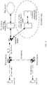
- An architecture of a 5G satellite communication system is shown in FIG. 3 .
- a terrestrial terminal device accesses a network through a 5G new radio interface.
- a 5G base station is deployed on a satellite and is connected to a terrestrial core network through a radio link.
- radio links between satellites to implement signaling exchange and user data transmission between base stations.
- the devices and interfaces in FIG. 3 are described as follows.
- the 5G core network provides services such as user access control, mobility management, session management, user security authentication, and accounting.
- the 5G core network includes a plurality of functional units, and can be divided into a control-plane functional entity and a data-plane functional entity.
- An access and mobility management unit (AMF) is responsible for user access management, security authentication, and mobility management.
- a user plane unit (UPF) manages user-plane data transmission, traffic statistics collection, and lawful interception.
- a ground station is responsible for forwarding signaling and service data between a satellite base station and a 5G core network.
- the 5G new radio is a radio link between a terminal and a 5G base station.
- the Xn interface is an interface between a 5G base station and a base station, and is used for switching signaling exchange and the like.
- the NG interface is an interface between a 5G base station and a 5G core network, and is mainly used for exchange of NAS signaling of the core network and user service data.
- the satellite when a satellite works in a regeneration mode, the satellite may be considered as a base station, or the satellite has some functions of the base station.
- a gateway station When the satellite works in the transparent transmission mode, a gateway station may be considered as a base station, or the gateway station has some functions of the base station.
- the network device in the terrestrial network communication system and the satellite in the NTN communication system may be uniformly considered as network devices.
- An apparatus configured to implement a function of a network device may be a network device, or may be an apparatus, for example, a chip system, that can support the network device in implementing the function.
- the apparatus may be mounted in the network device.
- an example in which the apparatus configured to implement a function of a network device is a satellite is used to describe the technical solutions provided in the embodiments of this application. It may be understood that, when the method provided in the embodiments of this application is applied to the terrestrial network communication system, an action performed by the satellite may be performed by a base station or a network device.
- an apparatus configured to implement a function of a terminal device may be a terminal device, or may be an apparatus, for example, a chip system, that can support the terminal device in implementing the function.
- the apparatus may be mounted in the terminal device.
- the chip system may include a chip, or may include a chip and another discrete component.
- the signal period is a period in which a network device sends a downlink signal to the terminal by using a length of the period as a metric.
- the terminal receives the downlink signal from the network device based on the signal period.
- the signal period may be an update period of the downlink signal.
- the network device may indicate the signal period to the terminal, and the terminal receives the signal period from the network device.
- the signal period may be a period in which the network device sends any signal.
- the signal period may be a modification period (modification period) of system information.
- the modification period indicates a period for the system to update system information.
- SFN system frame number
- m is a quantity of system frames forming a modification period.
- a possible value of m is 64, 128, 256, 512, 1024, or the like. Therefore, after obtaining a system modification period, the terminal obtains the signal period, so that signaling overheads of sending the signal period configuration by the network device to the terminal can be reduced, and power consumption of receiving signaling by the terminal can also be reduced.
- one signal period includes P frames, where P is a positive integer.
- the P frames in a frame period may be distinguished based on system frame numbers 0 to P.
- a length of the P frames is a length of the signal period, a length of one frame is 10 milliseconds (millisecond, ms), and the length of the signal period is P ⁇ 10 milliseconds.
- a start frame of the signal period is a start frame of the signal period, and a start moment of a frame whose system frame number is 0, P, 2P, 3P, 4P... is a start moment of each signal period.
- P 512
- 512... is a start moment of the signal period.
- SUFN indicates a subframe number.
- subframes whose subframe numbers are 0, 5, 10, 15, ... are start subframes of each signal period.
- Start moments whose subframe numbers are 0, 5, 10, 15, ... are start moments of each signal period.
- the length of the signal period is a length of five subframes (that is, five milliseconds).
- the length of the signal period may be agreed on in a protocol or configured by using signaling, or a start point of each signal period may be agreed on in a protocol or configured by using signaling.
- the period is a duration distributed at an equal interval on a time axis.
- the period is 1 minute, 1 second (second, s), 2 seconds, 500 ms, 250 ms, or 200 ms continuously distributed on the time axis.
- time_referencepoint 0 (unit: second). This indicates that start moments of a second second, a fourth second, and a sixth second in each minute is a start moment of the period.
- the millisecond may be represented by ms, and the second may also be represented by s.
- the length of the period may be agreed on in a protocol or configured by using signaling, or a start moment of each period may be agreed on in a protocol or configured by using signaling. This is more flexible. In this embodiment of this application, it is assumed that the length of the period and the start moment of each period are agreed on in a communication protocol.
- the length of the period may be greater than the length of the signal period, or the length of the period may be less than the length of the signal period, or the length of the period may be equal to the length of the signal period.
- the network device may be a gateway station in a transparent transmission mode or a satellite in a regeneration mode.
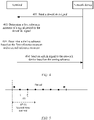
- a network device sends a downlink signal to a terminal, and the terminal receives the downlink signal from the network device.
- S402 The terminal determines a first reference moment of a signal period of the downlink signal.
- the first reference moment may be a start receiving moment of receiving the signal period. Due to a signal transmission delay, for the network device and the terminal, a same signal period has a specific offset on a time axis. A start moment of the signal period determined by the terminal based on the received downlink signal is different from a start moment of a signal period when the network device sends the downlink signal. For differentiation, the start moment of the signal period determined by the terminal based on the received downlink signal may be denoted as a start receiving moment. The start moment of the signal period when the network device sends the downlink signal is denoted as a start sending moment.
- the terminal determines the first reference moment based on the time at which the downlink signal is received.
- the first reference moment may be a start moment of the signal period. It is assumed that the signal period is a frame period.
- the terminal determines that the downlink signal is located in a start frame of the signal period, and determines, based on a moment at which the downlink signal is received, that a start moment of the frame in which the downlink signal is located is the start moment of the signal period.
- the terminal determines that the downlink signal is located in a frame in which a system frame number n in the signal period, and n is greater than or equal to 0, the terminal deduces a start moment of a start frame of the signal period based on a start moment of the system frame number n, that is, obtains a time at which the start moment of the signal period is received.
- S403 The terminal determines a timing advance based on the first reference moment and a second reference moment.
- the second reference moment may be a start sending moment of the signal period.
- S404 The terminal sends an uplink signal to the network device based on the timing advance.
- the timing advance may be determined in the following manner.
- the timing advance is round-trip time (round-trip time, RTT).
- RTT round-trip time
- the RTT is a difference multiplied by 2, and the difference may be a difference between a first reference moment t1 and a second reference moment t0.
- TA_value 2 x (t1 - t0).
- the difference is a difference between the start receiving moment and the start sending moment.
- the timing advance is a sum or a difference between the RTT and an adjustment value
- the adjustment value (T_adju) is related to a signal processing time and/or a relative motion between the network device and the terminal.
- TA_value RTT+T_adju
- T adju may be a positive value, a negative value, or zero.
- time_unit 16 ⁇ 64/2u/( ⁇ f ⁇ Nf), where u is related to a subcarrier spacing, and the subcarrier spacing is 2u ⁇ 15 KHz.
- rounding down ⁇ . ⁇ is used.
- rounding up ⁇ . ⁇ may be used instead of rounding down to obtain the TA value.
- the first reference moment is the start receiving moment of the signal period
- the second reference moment is the start sending moment of the signal period.
- the terminal may determine the start sending moment of the signal period based on a first time interval, and then determine the timing advance based on the start sending moment and the start receiving moment.
- the first time interval is a time interval between the start receiving moment and a start moment of a first period.
- the first period is a period in durations distributed at equal intervals on a time axis, and the start receiving moment is located in the first period. For example, the period is 1s, and each second on the time axis is a period.
- the first time interval is an interval between the start receiving moment and a start moment of a second in which the start receiving moment is located. It is assumed that the start receiving moment is 14.04 seconds, the first time interval is an interval between 14.04 seconds and 14.00 seconds, that is, 0.04 seconds.
- the start sending moment and the start receiving moment may be located in a same period, or may be located in different periods. If the terminal knows whether the start sending moment and the start receiving moment are in a same period, the terminal may calculate the start sending moment based on the start receiving moment and a period.
- the second period is a period in durations distributed at equal intervals on a time axis.
- the terminal may determine whether the start receiving moment and the start sending moment are in a same period, and determine the start sending moment based on an obtained determining result.
- the network device sends information about a second time interval to the terminal, where the second time interval is a time interval between the start sending moment and the start moment of the second period.
- the terminal may determine the start sending moment of the signal period based on a value relationship between the first time interval and the second time interval.
- the start receiving moment and the start sending moment are in a same period, and the second period and the first period are a same period.
- the start sending moment is obtained by postponing the start moment of the first period by the second time interval. For example, if the period is one second, the start receiving moment and the start sending moment are within a same second.
- the start receiving moment and start sending moment are not in a same period, and the first period may be a period following the second period.
- the start sending moment is a moment obtained by advancing the start moment of the second time interval by the second period.
- the start moment of the second period is obtained by advancing the start moment of the first period by the first period. For example, if the period is one second, the start sending moment is within one second before the start receiving moment. If it is known that the start receiving moment is within a second, a second in which the start sending moment may be deduced, and based on the second time interval notified by the network device, the start sending moment may be obtained by postponing the second time interval.
- the network device may notify the terminal of the period in which the start sending moment is located.
- the network device sends first indication information to the terminal, and the terminal receives the first indication information from the network device.
- the first indication information indicates a period in which the start sending moment is located, that is, the second period.
- the terminal determines, based on the first indication information, whether attributes of duration sequence numbers of the first period and the second period on the time axis are the same. If the attributes of the duration sequence numbers of the first period and the second period on the time axis are the same, the terminal determines that the start receiving moment and the start sending moment are in the same period, and the second period and the first period are a same period. If the attributes of the duration sequence numbers of the first period and the second period on the time axis are not the same, the terminal determines that the start receiving moment and the start sending moment are not in the same period, and the first period is a period following the second period.
- the period is one second
- the first indication information indicates whether the second period is an odd second or an even second. If the terminal knows whether the first period in which the start receiving moment is located is an odd second or an even second, the terminal may determine whether an attribute of the first period is the same as an attribute of the second period. If both the first period and the second period are odd seconds or even seconds, ti indicates that the two periods are the same. If the first indication information indicates an odd number, but the second period is an even second, or the first indication information indicates an even number, but the second period is an odd second, it indicates that the first period and the second period are not in a same second.
- the network device indicates, to the terminal by using the first indication information, a second in which the start sending moment is located.
- one bit may be used to indicate whether the second in which the start sending moment is located is an odd number or an even number.
- the start sending moment may be in seconds 2, 4, 6, 8, 10, 12, and the like in each minute.
- the network device sends the information about the second time interval to the terminal.
- the following describes the information about the second time interval.
- the information about the second time interval may indicate a time value of the second time interval, or may indicate a quantity.
- the quantity indicates a quantity of time units or a quantity of unit time included in the second time interval.
- One period may be divided into a plurality of equal-length time units or unit time.
- the terminal may calculate the second time interval based on the quantity.
- Table 1 Signaling 00000 00001 00010 00011 00100 00101 00110 00111 01000 01001 01010 01011 01100 ⁇ t (s) 0 0.04 0.08 0.12 0.16 0.2 0.24 0.28 0.32 0.36 0.4 0.44 0.48 Signaling 01101 01110 01111 10000 10001 10010 10011 10100 10101 10110 10111 11000 ⁇ t (s) 0.52 0.56 0.6 0.64 0.68 0.72 0.76 0.8 0.84 0.88 0.92 0.96
- Table 1 shows a correspondence between the information about the second time interval and the time value.
- the information about the second time interval is represented by signaling, and the time value of the second time interval is represented by ⁇ t.
- the period is one second, and five bits are used to represent 25 second time intervals in one second. For example, 00001 indicates 0.04 seconds, and 01100 indicates 0.48 seconds.
- the period is 500 ms, that is, 0.5s.
- Five bits may be used to represent 25 second time intervals within 0.5s.
- 00001 indicates 0.02 seconds
- 01100 indicates 0.24 seconds.
- Table 2 Signaling 00000 00001 00010 00011 00100 00101 00110 00111 01000 01001 01010 01011 01100 ⁇ t (s) 0 0.02 0.04 0.06 0.08 0.10 0.12 0.14 0.16 0.18 0.20 0.22 0.24
- the terminal may further determine the second time interval in the following manner.
- An interval between the start sending moment and the start moment of the period is the second time interval, and the second time interval may be greater than or equal to 0. If the second time interval is greater than 0, when a signal period is advanced on the time axis, a start sending moment of a signal period is aligned with a start moment of a period.
- the signal period may be referred to as a reference signal period, and the period is denoted as a third period.
- a difference between a start sending moment of the reference signal period and the start moment of the period may be a fixed value, which is denoted as a first fixed value.
- the first fixed value may be any value greater than 0, less than 0, or equal to 0.
- the network device may send second indication information to the terminal, where the second indication information indicates a reference signal period.
- the second indication information is represented as a signal-period alignment indication (sig_time_align).
- the second indication information may indicate a nonnegative integer, indicate a distance between a current signal period for sending a downlink signal and the reference signal period, and indicate a difference of several signal periods.
- the second indication information indicates 3, indicating that there is a difference of three signal periods between the start moment of the current signal period for sending the downlink signal and a start moment of the reference signal period.
- the second indication information indicates 0, it indicates that the current signal period for sending the downlink signal is the reference signal period, and a start moment of the current signal period for sending the downlink signal is aligned with or different from the start moment of the second period by a first fixed value.
- a second time interval ⁇ t between a start moment of the signal period for receiving the downlink signal and the start moment of the second period can be calculated.
- the start sending moment of the reference signal period is aligned with or differs from the start moment of the third period by the first fixed value.
- the first fixed value is greater than 0, less than 0, or equal to 0.
- the start sending moment of the reference signal period is aligned with the start moment of the third period.
- the start sending moment of the reference signal period is aligned with the start moment of the third period. If the first fixed value is greater than 0, the start sending moment of the reference signal period is in the third period. Alternatively, if the first fixed value is less than 0, the start sending moment of the reference signal period is in a period previous to the third period.
- the terminal determines the second time interval based on a time distance between the start receiving moment of the signal period of the downlink signal and the start receiving moment of the reference signal period.
- the second time interval is a value obtained by adding the time distance and the first fixed value and performing a modulo operation on one period.
- the second reference moment and/or the second reference moment may also be any moment specified in the signal period.
- the second reference moment is specified as a start sending moment of a second system frame in the signal period.
- the second time interval is a time interval between the second reference moment and a start moment of a period in which the second reference moment is located.
- a start moment of a period is used as a reference point for calculation.
- the time interval may be calculated by using any moment in the period as a reference point. For example, a location 0.1s away from a start moment in each period is used as the reference point.
- reference points of periods selected for the first time interval and the second time interval may be a same moment.
- the second time interval is a time interval between the second reference moment and a specified reference point of the period in which the second reference moment is located.
- a related solution of the foregoing start sending moment may alternatively be any specified moment in the signal period.
- the foregoing solution of the start moment of the period may alternatively be any reference point specified in the period.
- the terminal may be notified of specified reference points of the first reference moment, the second reference moment, and the period by using a protocol specification or a signaling notification manner.
- coordinated universal time Coordinated Universal Time, UTC
- UTC Coordinated Universal Time
- another time may be used to replace the UTC time as the reference moment.
- Beijing time Pacific standard time (Pacific standard time), Newfoundland standard time (Newfoundland standard time), time measured in binary, or, time measured in octal may be used as the reference moment.
- the following uses an example in which the signal period may be a modification period of the system information.
- one signal period represents a period in which the system updates system information.
- SFN is a system frame number.
- P is a quantity of system frames included in one signal period. For example, a possible value of P is 64, 128, 256, 512, or the like.
- a signal period includes P frames, and a frame whose system frame number is 0, P, 2P, 3P, 4P... is a start frame of a signal period.
- a start moment of the start frame is a start moment of the signal period.
- a start moment of a corresponding signal period in which a network device sends a downlink signal is a start sending moment.
- a start moment of a signal period in which a terminal receives the downlink signal is a start receiving moment. Durations distributed at equal intervals on a time axis form a plurality of periods. For example, the period is 1 second.
- the terminal When obtaining a modification period of the system information, the terminal obtains the signal period.
- a definition or signaling is no needed for notifying the signal period.
- the period may be notified to the terminal in a manner specified in a protocol or notified by using the signaling.
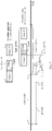
- the signal period includes P frames whose frame numbers are 0 to (P-1).
- a start receiving moment t1 is a first reference moment
- a start sending moment t0 is a second reference moment.
- t1 and t0 are absolute times on the time axis, and may be UTC time, or may be other types of time based on time synchronization between the terminal and the network device.
- An interval between the start receiving moment t1 and a start moment of a period in which the start receiving moment t1 is located is a first time interval ⁇ tr.
- An interval between the start sending moment t0 and a start moment of a period in which the start sending moment t0 is located is a second time interval ⁇ t.
- the network device starts to send a signal period of a frame 0 to a frame (P-1) at t0.
- the terminal receives a downlink signal in the signal period.
- the terminal may receive the downlink signal at a start frame of the signal period, or may receive the downlink signal in a frame after the start frame of the signal period. Regardless of which frame of the signal period the terminal receives the downlink signal, the terminal may determine the start moment of the start frame of the signal period based on information about a frame number (and/or a subframe number) of a currently received downlink signal.
- a length between the start frame and the frame 1 is a length of one frame, that is, 0.01 seconds
- the start moment of the start frame of the signal period is 14.29 seconds
- the start receiving moment t1 is 14.29 seconds.
- the terminal may determine, based on a value relationship between ⁇ t and ⁇ tr, whether t1 and t0 are in a same second.
- the terminal may determine that the network device sends a start frame of the signal period starting from a previous second.
- the terminal may determine that sending the downlink signal by the network device and receiving the downlink signal by the terminal are within a same second.
- T_adju is related to factors such as a signal processing time and relative movement between the network device and the terminal, and may be a positive value, a negative value, or zero.
- FIG. 6 is shown by using an example in which ⁇ tr ⁇ t. It can be learned that the start sending moment is within an nt h period, and the start receiving moment is within an (n+1) th period.
- the network device starts to send a start frame of a signal period in a 6 th second.
- An interval between a frame whose number is 1 and the start frame is the length of one frame, that is, 0.01 seconds.
- the terminal determines, based on a value relationship between ⁇ t and ⁇ tr, a second at which the network device starts to send the start frame of the modification period. Because ⁇ tr ⁇ t, it can be learned that the network device starts to send the start frame of the modification period within 1 second before the terminal receives the start moment of the modification period.
- a subcarrier spacing is 15 kHz.
- the network device starts to send a start frame of a signal period in a 6 th second.
- An interval between a frame whose number is 1 and the start frame is the length of one frame, that is, 0.01 seconds.
- a time interval between the start receiving moment of the modification period received by the terminal and the start moment of 1 second
- the terminal does not need to calculate a value of ⁇ tr, but determines, based on the condition that is met by a second in which the start sending moment is located and that is indicated by the network device, a second in which the start sending moment is located.
- An arrow indicating, by the network device shown in FIG. 8 , a condition met by a second in which the start sending moment is located does not represent a time domain location, and may be sent at any moment.
- the network device may also indicate, to the terminal by using signaling, 500 milliseconds in which the start moment of the signal period or the modification period is located. For example, signaling of 1 bit is used to indicate that the start sending moment is a first half 500 milliseconds or a second half 500 milliseconds in each second.
- the terminal may further determine the second time interval by using second indication information sent by the network device.
- the second indication information indicates a reference signal period.
- the signal period includes P frames whose frame numbers are 0 to (P-1).
- a start receiving moment t1 is a first reference moment
- a start sending moment t0 is a second reference moment.
- t1 and t0 are absolute times on the time axis, and may be UTC time, or may be other types of time based on time synchronization between the terminal and the network device.
- An interval between the start receiving moment t1 and a start moment of a period in which the start receiving moment t1 is located is a first time interval ⁇ tr.
- An interval between the start sending moment t0 and a start moment of a period in which the start sending moment t0 is located is a second time interval ⁇ t.
- the network device does not directly indicate the information about the second time interval to the terminal, but sends the second indication information to the terminal, to indicate the reference signal period.
- a reference signal period before the signal period, there is a reference signal period.
- a start sending moment of a start frame of the reference signal period is aligned with a start moment of an (n-y) th period.
- y is a non-negative integer.
- a difference between the start sending moment of the start frame of the reference signal period and the start moment of the period may also be a fixed value.
- the start sending moment of the start frame of the reference signal period is aligned with the start moment of the duration.
- the terminal needs to determine a period in which the second reference moment is located, to determine a specific value of the second reference moment, and further determine the timing advance based on the first reference moment and the second reference moment.
- another optional manner is provided to determine a specific value of a second reference moment. Details are as follows:
- the length of the period is M times the length of the signal period.
- M is a value greater than 0.
- M may be a value greater than 1, and the length of the period is greater than the length of the signal period.
- M may be a value less than 1, and the length of the period is less than the length of the signal period.
- the second reference moment is aligned with or differs from a start moment of the period by a second fixed value.
- the second fixed value may be a value greater than 0, less than 0, or equal to 0.
- the second reference moment may be at a position after or before the start moment of the period or at an aligned position.
- the start moment of the period may be replaced with "any specified time of the period”.
- the terminal may determine, based on the first reference moment, the start moment of the first period in which the first reference moment is located.
- the terminal determines, based on the start moment of the first period and the second fixed value, the start sending moment of the signal period.
- the terminal After determining the first reference moment, the terminal determines which 1/M of the first period the first reference moment is in, to determine the start moment of the first period. The terminal determines the start sending moment of the signal period based on the start moment of the first period, a 1/M th 1/M of the first reference moment, and the second fixed value.
- the start sending moment of the signal period may be determined by postponing or advancing the start moment of the first period by [z ⁇ signal period length+second fixed value]. z is a positive integer.
- the terminal After receiving the downlink signal, the terminal determines a moment of the first reference moment in the first period in which the terminal is located, and further determines the start moment of the first period. The terminal may determine, based on the start moment of the first period and the second fixed value, the start sending moment of the signal period. The start sending moment of the signal period is determined by advancing or postponing the start moment of the first period by the second fixed value.
- the length of the period is the same as that of the signal period, and the start sending moment of the signal period is aligned with the start moment of the period.
- the terminal may determine the start receiving moment t1 of the signal period in which the received downlink signal is located, determine t0 based on t1, and do not need to calculate the first time interval ⁇ tr.
- the network device does not need to notify information about the second time interval ⁇ t or the first indication information. Further, the timing advance is determined based on t1 and t0.
- the network device further sends indication information to the terminal, where the indication information is denoted as third indication information.
- the terminal receives the third indication information from the network device.
- the third indication information indicates the length of the signal period and/or the value of M.
- the length of the signal period and/or the value of M may be specified by using a protocol. If a default length of the signal period is the same as the length of the period, the length of the signal period may be notified by using signaling or specified in a protocol, and the value of M does not need to be notified or specified.
- the signal period is a positive integer multiple of 250 ms.
- the length of the signal period is 250 ms, and the length of the period may be equal to 250 ms, or the length of the period is 500 ms, 1s, 2s, 10s, 20s, or the like.
- the length of the period is 1s, the period is four times the signal period.
- a length of the modification period may be 64, 128, 256, 512, 1024, or the like. If a unit time is 1s, considering that the length of the modification period is not an integer multiple of the unit time, the length of the signal period may be set to an integer multiple of the unit time, and the length of the modification period is changed based om the length of the signal period. For example, the length of the signal period is defined as 10s, and a length close to the modification period is 10.24s.
- the modification period 10.24s of the system information may be changed to 10s. For example, 1 bit is used to indicate whether the modification period is 10.24s or 10s. If a value of bit 1 is 1, the modification period is 10s.
- the modification period is 10.24s. If the modification period is 10.24s, a frame number in the modification period ranges from 0 to 1023. If the modification period is 10s, the frame number in the modification period ranges from 0 to 999.
- the length of the signal period is 10.24 seconds, which is not a multiple of the unit time.
- the length of the signal period may be a multiple of the unit time.
- the length of the frame period may be configured for the terminal by using signaling. For example, 1 bit is used to indicate whether the length of the signal frame period is 1024 or 1000. Signaling consumption of indication of the length of the signal period is reduced.
- the start sending moment of the signal period is aligned with the start moment of the period.
- the start sending moment of the signal period is aligned with a start moment of 1s, 11s, 21s, 31s, 41s and 51s in each minute.
- the start moment of 1s, 11s, 21s, 31s, 41s and 51s in each minute is the second reference moment.
- the start sending moment of the signal period is aligned with start moments of a 3rd second, a 13 th second, a 23 rd second, a 33 rd second, and the like in each minute.
- a specific start second may not be agreed on, and it is agreed only that the start sending moment of the signal period is aligned with the start moment of the second in which the signal period is located.
- the terminal is notified, by using signaling, that the start sending moment of the signal period is aligned with a start moment of which second. For example, 4 bits are used to represent a number between 1 and 10, indicating that the start sending moment of the signal period is aligned with a start moment of a corresponding second.
- the start sending moment of the signal period may be aligned with a start moment of one second, or aligned with 500 ms in one second.
- One bit may be used to notify the terminal that the start moment of the signal period is aligned with the start moment of the one second or aligned with 500 ms in the one second.
- the signal period is not limited to 1024 or 1000, and may be set to another value, for example, 500 or 10000.
- t0 11.225 seconds.
- the network device sends the signal period at the moment t0.
- a network device may perform delay compensation on a received uplink signal, and a compensation value is delay compensated. That the network device performs delay compensation on the received uplink signal may be understood as performing delay processing on a receive window of the uplink signal.
- a definition of a second time interval indicated by the network device to the terminal remains unchanged. In other words, the second time interval ⁇ t is still calculated based on t0.
- the method may be used in combination with any one of the foregoing implementations.
- the TA determining method provided in embodiments of this application may also be compatible with an existing TA determining method.
- the network device may indicate, to the terminal, whether the TA determining method in embodiments of this application or another method is used. For example, the network device sends indication information to the terminal, where the indication information is 1 bit. When a value of the indication information is 1, it indicates that the TA determining method provided in the foregoing embodiments of this application is used.
- the network device and the terminal implement the TA determining method according to any possible method provided in the foregoing embodiments. When a value of the indication information is 0, it indicates that another TA determining method is used.
- the indication information when the indication information is 1, it indicates that the network device sends the downlink signal according to the method provided in the foregoing embodiments of this application, and the terminal may determine the TA value by using the method provided in the foregoing embodiments of this application.
- the indication information when the indication information is 0, it indicates that the network device does not send the downlink signal according to the method provided in the foregoing embodiments of this application, and the terminal does not determine the TA value by using the foregoing method in this application either.
- indication meanings of 1 and 0 may be interchanged.
- some signals or information is used, including a downlink signal and indication information.
- the indication information further includes the first indication information, the second indication information, the third indication information, the information about the second time interval, and the like.
- an expression form of the involved signal or information may be a message or signaling in any form described below, or the involved signal or information may be carried in or carried in a message in any form described below: at least one of broadcast information of a system information block (system information block, SIB) 1, other system information (other system information, OSI), a master information block (master information block, MIB), and the like.
- SIB system information block
- SIB system information block
- other system information other system information
- MIB master information block
- it may be agreed that a change of the indication information, the information about the second time interval, and the like does not generate a system information change notification, and does not cause a change of a tag value (value Tag) in the SIB 1.
- the network device performs unicast, broadcast (broadcast may be performed in a cell range, a beam range, or a BWP range), or multicast sending to the terminal.
- the network device may carry the information in at least one type of information of RRC information, an RRC reconfiguration (Reconfiguration) message, downlink control information (downlink control information, DCI), group DCI, a media access control (media access control, MAC) element (element), and timing advance command (TAC), or transmit the information with data, or carry the information in a separately allocated physical downlink shared channel (physical downlink shared channel, PDSCH) bearer.
- RRC radio resource control
- information may be carried in an RRCReconfiguration message, or may be carried in BWP-related signaling.
- a cell in communication notifies a terminal of at least one piece of information such as first indication information, second indication information, third indication information, second time interval information, a signal period, and a period of a target cell (or multiple target cells) by using RRCReconfiguration signaling.
- At least one of the first indication information, the second indication information, the third indication information, the second time interval information, the signal period, the period, and the like of the target beam in initial BWP signaling, BWP downlink common signaling (BWP-DownlinkCommon), BWP uplink common signaling (BWP-UplinkCommon), BWP downlink dedicated signaling (BWP-DownlinkDedicated), or BWP uplink dedicated signaling (BWP-UplinkDedicated) may be sent to the terminal.
- At least one piece of information of the first indication information, the second indication information, the third indication information, the second time interval information, the signal period, the period, and the like of the target cell (or the plurality of target cells) may be sent to the terminal by using neighboring cell measurement configuration signaling (MeasConfig).
- a beam may be indicated based on the BWP, the TCI, or the SSB.
- BWP bandwidth part
- TCI transmission configuration indicator
- SSB synchronization signal block
- a beam may be indicated based on the BWP, the TCI, or the SSB.
- switching between beams may be indicated by switching between BWPs, TCIs, or SSBs. Therefore, for the terminal and/or the network device, what is actually performed may be the switching between the BWPs, TCIs, or SSBs.
- the beam in this application may be replaced with the BWP, the TCI, or the SSB.
- the network device and the terminal may include a hardware structure and/or a software module, and implement the foregoing functions in a form of the hardware structure, the software module, or a combination of the hardware structure and the software module. Whether a function in the foregoing functions is performed by using the hardware structure, the software module, or the combination of the hardware structure and the software module depends on particular applications and design constraints of the technical solutions.
- an embodiment of this application further provides an apparatus 1200.
- the apparatus 1200 may be a terminal device or a network device, an apparatus in a terminal device or a network device, or an apparatus that can be used with a terminal device or a network device.
- the apparatus 1200 may include modules for performing the methods/operations/steps/actions performed by the terminal device or the network device in the foregoing method embodiments.
- the modules may be hardware circuits, may be software, or may be implemented by using the hardware circuits in combination with the software.
- the apparatus may include a processing module 1201 and a communication module 1202.
- the processing module 1201 is configured to invoke the communication module 1202 to perform a receiving and/or sending function.
- the communication module 1202 is further configured to perform an operation that is related to signal receiving or sending and that is performed by the terminal in the foregoing method embodiments.
- the processing module 1201 is further configured to perform another operation that is performed by the terminal in the foregoing method embodiments and that is other than signal receiving and sending. Details are not described herein again.
- the processing module 1201 is configured to: invoke the communication module 1202 to send indication information to a terminal, where the indication information determines, for the terminal, a timing advance for sending an uplink signal; and invoke the communication module 1202 to receive the uplink signal from the terminal.
- the indication information indicates information about a time interval.
- the time interval is an interval between a reference moment and a start moment of a period.
- the reference moment is located in the period.
- the period is one of durations distributed at equal intervals on a time axis.
- the indication information indicates an attribute of a duration sequence number of the period on the time axis.
- the attribute includes an odd number or an even number.
- the indication information indicates a reference signal period.
- a difference between a start moment of the reference signal period and a start moment of a period in which the start moment is located is a fixed value.
- the fixed value is greater than 0, less than 0, or equal to 0.
- the communication module 1202 is further configured to perform an operation related to signal receiving or sending and that is performed by the network device in the foregoing method embodiments.
- the processing module 1201 is further configured to perform another operation performed by the network device in the foregoing method embodiments and that is other than signal receiving and sending. Details are not described herein again.
- Division into the modules in embodiments of this application is an example, is merely division into logical functions, and may be other division during actual implementation.
- functional modules in embodiments of this application may be integrated into one processor, or each of the modules may exist alone physically, or two or more modules may be integrated into one module.
- the integrated module may be implemented in a form of hardware, or may be implemented in a form of a software functional module.
- FIG. 13 shows a communication apparatus 1300 according to an embodiment of this application.
- the communication apparatus 1300 is configured to implement functions of the terminal device or the network device in the foregoing method.
- the apparatus may be the network device, may be an apparatus in the network device, or an apparatus that can be used together with the network device.
- the apparatus may be the terminal device, an apparatus in the terminal device, or an apparatus that can be used together with the terminal device.
- the apparatus may be a chip system. In this embodiment of this application, the chip system may include a chip, or may include a chip and another discrete component.
- the communication apparatus 1300 includes at least one processor 1320, configured to implement functions of the terminal device or the network device in the method provided in embodiments of this application.
- the apparatus 1300 may further include a communication interface 1310.
- the communication interface may be a transceiver, a circuit, a bus, a module, or a communication interface of another type, and is configured to communicate with another device by using a transmission medium.
- the communication interface 1310 is used by an apparatus in the communication apparatus 1300 to communicate with the another device.
- the another device may be a terminal device.
- the another apparatus may be a network device.
- the processor 1320 receives and sends data through the communication interface 1310, and is configured to implement the method in the foregoing method embodiments.
- the processor 1320 is configured to: send indication information to a terminal through the communication interface 1310, and receive an uplink signal from the terminal.
- the indication information determines, for the terminal, a timing advance for sending the uplink signal.
- the indication information indicates information about a time interval.
- the time interval is an interval between a reference moment and a start moment of a period.
- the reference moment is located in the period.
- the period is one of durations distributed at equal intervals on a time axis.
- the indication information indicates an attribute of a duration sequence number of the period on the time axis.
- the attribute includes an odd number or an even number.
- the indication information indicates a reference signal period.
- a difference between a start moment of the reference signal period and a start moment of a period in which the start moment is located is a fixed value.
- the fixed value is greater than 0, less than 0, or equal to 0.
- the communication interface 1310 is configured to receive a downlink signal from the network device.
- the processor 1320 is configured to: determine a first reference moment of a signal period of the downlink signal, and determine a timing advance based on the first reference moment and a second reference moment;
- the communication interface 1310 is further configured to send the uplink signal to the network device based on the timing advance.
- the processor 1320 and the communication interface 1310 may further be configured to perform another corresponding steps or operation performed by the terminal device or the network device in the foregoing method embodiment. Details are not described herein again.
- the communication apparatus 1300 may further include at least one memory 1330, configured to store program instructions and/or data.
- the memory 1330 is coupled to the processor 1320.
- the coupling in this embodiment of this application may be an indirect coupling or a communication connection between apparatuses, units, or modules in an electrical form, a mechanical form, or another form, and is used for information exchange between the apparatuses, the units, or the modules.
- the processor 1320 may operate in collaboration with the memory 1330.
- the processor 1320 may execute the program instructions stored in the memory 1330. At least one of the at least one memory may be integrated with the processor.
- a specific connection medium between the communication interface 1310, the processor 1320, and the memory 1330 is not limited.
- the memory 1330, the processor 1320, and the communication interface 1310 are connected through a bus 1340.
- the bus is represented by a bold line in FIG. 13 .
- a connection manner between other components is merely an example for description, and is not limited thereto.
- the bus may be classified into an address bus, a data bus, a control bus, and the like. For ease of representation, only one bold line is used to represent the bus in FIG. 13 , but this does not mean that there is only one bus or only one type of bus.
- the communication module 1202 and the communication interface 1310 may output or receive baseband signals.
- the communication module 1202 and the communication interface 1310 may output or receive radio frequency signals.
- the processor may be a general-purpose processor, a digital signal processor, an application-specific integrated circuit, a field programmable gate array or another programmable logic device, a discrete gate or transistor logic device, or a discrete hardware component, and may implement or execute the methods, steps, and logical block diagrams disclosed in embodiments of this application.
- the general purpose processor may be a microprocessor or any conventional processor or the like. The steps of the method disclosed with reference to embodiments of this application may be directly performed by a hardware processor, or may be performed by using a combination of hardware in the processor and a software module.
- the memory 1330 may be a non-volatile memory, for example, a hard disk drive (hard disk drive, HDD) or a solid-state drive (solid-state drive, SSD), or may be a volatile memory (volatile memory), for example, a random-access memory (random-access memory, RAM).
- the memory is any other medium that can carry or store expected program code in a form of an instruction or a data structure and that can be accessed by a computer, but is not limited thereto.
- the memory in embodiments of this application may alternatively be a circuit or any other apparatus that can implement a storage function, and is configured to store the program instructions and/or the data.
- Some or all of the operations and functions that are performed by the terminal and that are described in the foregoing method embodiments of this application, or some or all of the operations and functions that are performed by the network device and that are described in the foregoing method embodiments of this application may be completed by using a chip or an integrated circuit.
- an embodiment of this application further provides a chip, including a processor, configured to support the communication apparatus in implementing the functions of the terminal device or the network device in the foregoing method embodiments.
- the chip is connected to a memory or the chip includes the memory, and the memory is configured to store program instructions and data that are necessary for the communication apparatus.
- An embodiment of this application provides a computer-readable storage medium that stores a computer program.
- the computer program includes instructions used to perform the foregoing method embodiments.
- An embodiment of this application provides a computer program product including instructions.
- the computer program product runs on a computer, the computer is enabled to perform the foregoing method embodiments.
- this application may be provided as a method, a system, or a computer program product. Therefore, this application may use a form of hardware only embodiments, software only embodiments, or embodiments with a combination of software and hardware. In addition, this application may use a form of a computer program product that is implemented on one or more computer-usable storage media (including but not limited to a disk memory, a CD-ROM, an optical memory, and the like) that include computer-usable program code.
- a computer-usable storage media including but not limited to a disk memory, a CD-ROM, an optical memory, and the like
- These computer program instructions may be provided for a general-purpose computer, a dedicated computer, an embedded processor, or a processor of any other programmable data processing device to generate a machine, so that the instructions executed by a computer or a processor of any other programmable data processing device generate an apparatus for implementing a specific function in one or more processes in the flowcharts and/or in one or more blocks in the block diagrams.
- These computer program instructions may be stored in a computer-readable memory that can instruct the computer or any other programmable data processing device to work in a specific manner, so that the instructions stored in the computer-readable memory generate an artifact that includes an instruction apparatus.
- the instruction apparatus implements a specific function in one or more processes in the flowcharts and/or in one or more blocks in the block diagrams.
- the computer program instructions may alternatively be loaded onto a computer or another programmable data processing device, so that a series of operations and steps are performed on the computer or the another programmable device, so that computer-implemented processing is generated. Therefore, the instructions executed on the computer or the another programmable device provide steps for implementing a specific function in one or more procedures in the flowcharts and/or in one or more blocks in the block diagrams.
Landscapes
- Engineering & Computer Science (AREA)
- Computer Networks & Wireless Communication (AREA)
- Signal Processing (AREA)
- Physics & Mathematics (AREA)
- Astronomy & Astrophysics (AREA)
- Aviation & Aerospace Engineering (AREA)
- General Physics & Mathematics (AREA)
- Mobile Radio Communication Systems (AREA)
- Synchronisation In Digital Transmission Systems (AREA)
Abstract
Description
- This application claims priority to
Chinese Patent Application No. 202010245958.2, filed with the China National Intellectual Property Administration on March 31, 2020 - Embodiments of this application relate to the field of communication technologies, and in particular, to a method for determining a timing advance and a communication apparatus.
- Currently, research institutes are studying evolution from terrestrial communication technologies and protocols to non-terrestrial networks (Non-Terrestrial networks, NTN) communication technologies, and attempt to unify sky, air, and ground communication protocols to form an integrated communication network. NTN communication includes satellite communication, air-to-ground (air to ground, ATG) communication, and the like. Compared with terrestrial communication, NTN communication has obviously different transmission features. NTN communication usually has a larger transmission delay. For example, round-trip time of geostationary earth orbit (geostationary earth orbit, GEO) satellite communication (regeneration mode) is 238 ms to 270 ms. Round-trip time of low earth orbit (LEO) satellite communication (
orbit altitude 1200 km, regeneration mode) is 8 ms to 20 ms. In an ATG communication scenario, maximum round-trip time may also reach 1 ms. - In the conventional technology, a maximum timing advance (timing advance, TA) range indicated in a random access response (random access response, RAR) is 0 ms to 2 ms. As a subcarrier spacing increases, a TA range that can be indicated in the RAR also decreases exponentially. When the subcarrier spacing is greater than 30 KHz, an indicated TA range in the RAR is less than 1 ms.
- It is clearly that, for an NTN communication scenario, the maximum TA range of 2 ms that can be indicated in the RAR is insufficient to indicate round-trip time length in the NTN communication scenario.
- Embodiments of this application provide a method for determining a timing advance and a communication apparatus, to resolve a problem that a method for indicating a TA in an RAR is insufficient to indicate round-trip time length in an NTN communication scenario.
- According to a first aspect, a method for determining a timing advance is provided. The method may be applied to a terminal. The method may be applied to but is not limited to a scenario of communicating with an NTN. The method is implemented by using the following steps: receiving a downlink signal from the network device, determining a first reference moment of a signal period of the downlink signal, determining a timing advance based on the first reference moment and a second reference moment, and sending an uplink signal to the network device based on the timing advance. The signal period is a period in which the network device sends the downlink signal, and the terminal may receive the downlink signal at some or all moments in the signal period. The second reference moment is determined based on a first time interval. The first time interval is an interval between the first reference moment and a start moment of a first period. The first reference moment is located in the first period. A period is a duration distributed at an equal interval on a time axis. The first period is one of durations on the time axis.
- In a design of forming the period by using the duration distributed at the equal interval on the time axis, and using a reference point at which the downlink signal periodically appears, the terminal can determine the timing advance based on the first reference moment, the second reference moment, and the period. The network device does not need to indicate a value of the TA by using signaling. This can effectively reduce signaling overheads for determining the TA on a terminal side. When the method is applied to the NTN scenario, a value of the TA in a long range may be determined by using the method in this embodiment of this application, to avoid a problem that a method for indicating a TA in an RAR is insufficient to indicate round-trip time in the NTN scenario. In a random access scenario, a timing range in which a random access preamble sent by the terminal arrives at the network device is large. According to the method in this embodiment of this application, a length of a cyclic prefix of the random access preamble can be reduced.
- In a possible design, the first reference moment is a start receiving moment of the signal period, and the second reference moment is a start sending moment of the signal period. The start receiving moment and the start sending moment of the signal period are used as reference moments, so that complexity of calculating the TA on the terminal side can be reduced.
- In a possible design, the start sending moment is located in a second period, and the second period is a duration on the time axis. The method includes: determining whether the start receiving moment and the start sending moment are in a same period; and determining the start sending moment based on a determining result. It can be determined, by determining whether the start receiving moment and the start sending moment are in the same period, whether the start sending moment is in the period of the start receiving moment or in a period preceding the period including the start receiving moment. Because a start moment of the period including the start receiving moment can be obtained by the terminal through measurement, the start sending moment can be further calculated, to determine a value of the TA.
- There are several optional manners for determining whether the start receiving moment and the start sending moment are in the same period.
- Optional manner 1: An interval between the start sending moment and a start moment of a second period is a second time interval. If the first time interval is not less than the second time interval, the start receiving moment and the start sending moment are in a same period, and the second period and the first period are a same period. Alternatively, if the first time interval is less than the second time interval, the start receiving moment and the start sending moment are not in a same period, and the first period is a period following the second period.
- Optionally, when the determining result is that the start receiving moment and the start sending moment are in the same period, the start sending moment is a moment obtained by postponing the start moment of the first period by the second time interval. When the determining result is that the start receiving moment and the start sending moment are not in the same period, the start sending moment is a moment obtained by postponing the start moment of the second period by the second time interval. The start moment of the second period is a moment obtained by advancing the start moment of the first period by a period.
- This method is applicable when the period is greater than a maximum one-way delay. The following
optional manner 2 is not only applicable to a case in which the period is greater than the maximum one-way delay, but also applicable to a case in which the period is less than or equal to the maximum one-way delay. - Optional manner 2: The method includes: receiving first indication information from the network device. The first indication information indicates an attribute of a duration sequence number of the second period on the time axis, and the attribute includes an odd number or an even number. The method includes determining, based on the first indication information, whether attributes of duration sequence numbers of the first period and the second period on the time axis are the same. If the attributes of the duration sequence numbers of the first period and the second period on the time axis are the same, it is determined that the start receiving moment and the start sending moment are in the same period, and the second period and the first period are a same period. If the attributes of the duration sequence numbers of the first period and the second period on the time axis are not the same, it is determined that the start receiving moment and the start sending moment are not in the same period, and the first period is a period following the second period.
- In a possible design, the method includes receiving second indication information from the network device. The second indication information indicates a reference signal period. A difference between a start sending moment of the reference signal period and a start moment of a third period is a first fixed value. The first fixed value may be any value greater than or equal to 0. The start sending moment of the reference signal period is located in the third period. The method includes: determining the second time interval based on a distance between a start moment of the signal period of the downlink signal and the start sending moment of the reference signal period. The second time interval is obtained by adding the distance and the first fixed value and then performing a modulo operation on one period. Optionally, the first fixed value may also be less than 0. In this way, the second time interval is a value obtained by subtracting the first fixed value from the distance and then performing a modulo operation on one period. In this way, the terminal may calculate the second time interval by indicating the first fixed value, thereby further reducing signaling overheads.
- In a possible design, the method includes: receiving third indication information from the network device, where the third indication information indicates the second time interval. The second time interval is a time value or a quantity. The quantity indicates a quantity of time units included in the second time interval. The period is divided into a plurality of time units. This design provides a more flexible manner of indicating the second time interval.
- In a possible design, the determining the timing advance based on the start receiving moment and the start sending moment is specifically implemented in any one of the following manners: The timing advance is a difference multiplied by two, and the difference is a difference between the start receiving moment and the start sending moment; or the timing advance is a sum or a difference between a difference multiplied by 2 and an adjustment value, and the adjustment value is related to a signal processing time and/or relative movement between the network device and the terminal.
- Optionally, the signal period may be a modification period of system information. In this way, after obtaining a system modification period, the terminal obtains the signal period, so that signaling overheads of sending the signal period configuration by the network device to the terminal can be reduced, and power consumption of receiving signaling by the terminal is also reduced.
- According to a second aspect, a method for determining a timing advance is provided. The method may be performed by a terminal. The method is implemented by using the following steps: receiving a downlink signal from the network device, determining a first reference moment of a signal period of the downlink signal, determining a timing advance based on the first reference moment and a second reference moment, and sending an uplink signal to the network device based on the timing advance. The signal period is a period in which the network device sends a downlink signal. A length of a period is M times a length of the signal period. M is a value greater than 0. The period is a duration distributed at an equal interval on a time axis. When M=1, the length of the period is the same as the length of the signal period. M may be a value greater than 1, and the length of the period is greater than the length of the signal period. Alternatively, M may be a value less than 1, and the length of the period is less than the length of the signal period. It is set that the second reference moment is aligned with or differs from a start moment of the period by a fixed value. Alternatively, it is set that the second reference moment is aligned with or differs from any specified moment of the period by a fixed value. The fixed value may be a value greater than 0, less than 0, or equal to 0.
- By designing of forming the period by using the duration distributed at the equal interval on the time axis, using a reference point at which the downlink signal periodically appears, and setting a relationship between the signal period and the period, when a terminal measures the downlink signal, a start sending moment of a period at which the network device sends a signal may be deduced based on time of the downlink signal, to further determine the timing advance. The network device does not need to indicate a value of the TA by using signaling, so that signaling overheads for determining the TA on a terminal side can be effectively reduced. When the method is applied to the NTN scenario, a value of the TA in a long range may be determined by using the method in this embodiment of this application, to avoid a problem that a method for indicating a TA in an RAR is insufficient to indicate round-trip time in the NTN scenario. In a random access scenario, a timing range in which a random access preamble sent by the terminal arrives at the network device is large. According to the method in this embodiment of this application, a length of a cyclic prefix of the random access preamble can be reduced.
- In a possible design, the first reference moment is a start receiving moment of the signal period, and the second reference moment is a start sending moment of the signal period. The start receiving moment and the start sending moment of the signal period are used as reference moments, so that complexity of calculating the TA on the terminal side can be reduced.
- In a possible design, it is assumed that M=1, and the length of the period is the same as the length of the signal period, the terminal may determine, based on the first reference moment, a start moment of a first period in which the first reference moment is located. The terminal determines, based on the start moment of the first period and a second fixed value, the start sending moment of the signal period.
- It is assumed that M>1, that is, the period is M times the signal period. After determining the first reference moment, the terminal determines which 1/M of the first period the first reference moment is in, to determine the start moment of the first period. The terminal determines the start sending moment of the signal period based on the start moment of the first period, a 1/
M th 1/M of the first reference moment, and the second fixed value. - In a possible design, the second fixed value is equal to 0, and the start sending moment is the start moment of the period. Alternatively, the second fixed value is less than 0, and the start sending moment obtained by advancing the start moment of the period by the fixed value. Alternatively, the second fixed value is greater than 0, and the start sending moment is obtained by postponing the start moment of the period by the fixed value.
- In a possible design, the method includes receiving indication information from the network device, where the indication information indicates the length of the signal period. A specific value of the length of the signal period may be indicated, or one bit may be used to indicate whether a first value or a second value is selected for the signal period. The first value is a newly defined value, and the second value is a value of a regular modification period of system information.
- In a possible design, the length of the signal period is a positive integer multiple of 250 ms.
- In a possible design, the determining the timing advance based on the start receiving moment and the start sending moment is specifically implemented in any one of the following manners: The timing advance is a difference multiplied by two, and the difference is a difference between the start receiving moment and the start sending moment; or the timing advance is a sum or a difference between a difference multiplied by 2 and an adjustment value, and the adjustment value is related to a signal processing time and/or relative movement between the network device and the terminal.
- Optionally, the signal period may be a modification period of system information. In this way, after obtaining a system modification period, the terminal obtains the signal period, so that signaling overheads of sending the signal period configuration by the network device to the terminal can be reduced, and power consumption of receiving signaling by the terminal is also reduced.
- According to a third aspect, a method for determining a timing advance is provided. The method may be applied to a network device. The method may be applied to but is not limited to a scenario of communicating with an NTN. The method is implemented by using the following steps: sending indication information to a terminal, where the indication information determines, for the terminal, a timing advance for sending an uplink signal; and receiving the uplink signal from the terminal. The indication information indicates information about a time interval. The time interval is an interval between a reference moment and a start moment of a period. The reference moment is located in the period. The period is one of durations distributed at equal intervals on a time axis. Alternatively, the indication information indicates an attribute of a duration sequence number of the period on the time axis. The attribute includes an odd number or an even number. Alternatively, the indication information indicates a reference signal period. A difference between a start moment of the reference signal period and a start moment of a period in which the start moment is located is a fixed value. The fixed value is greater than 0, less than 0, or equal to 0.
- By designing of forming the period by using the duration distributed at the equal interval on the time axis, and using a reference point at which the downlink signal periodically appears, some information related to the period may be indicated to the terminal by using indication information, so that the terminal determines the timing advance based on the indication information. The network device does not need to indicate a value of the TA by using signaling, so that signaling overheads for determining the TA on a terminal side can be effectively reduced. When the method is applied to the NTN scenario, a value of the TA in a long range may be determined by using the method in this embodiment of this application, to avoid a problem that a method for indicating a TA in an RAR is insufficient to indicate round-trip time in the NTN scenario. In a random access scenario, a timing range in which a random access preamble sent by the terminal arrives at the network device is large. According to the method in this embodiment of this application, a length of a cyclic prefix of the random access preamble can be reduced.
- In a possible design, the method includes periodically sending a downlink signal based on a signal period. A start sending moment of the signal period is the reference moment, or the start sending moment of the signal period is a moment determined by combining the reference moment and a delay compensation value. A delay compensation value may be used to reduce round-trip time.
- In a possible design, when the first indication information indicates the information about the time interval, first indication information is a time value or a quantity. The quantity indicates a quantity of time units included in the time interval. The period is divided into a plurality of time units. This design provides a more flexible manner of indicating the time interval.
- According to a fourth aspect, a method for determining a timing advance is provided. The method may be applied to a network device. The method may be applied to but is not limited to a scenario of communicating with an NTN. The method is implemented by using the following steps: sending a downlink signal based on a signal period. A length of a period is M times a length of the signal period. M is a value greater than 0, and the period is a duration distributed at an equal interval on a time axis. When M=1, the length of the period is the same as the length of the signal period. M may be a value greater than 1, and the length of the period is greater than the length of the signal period. Alternatively, M may be a value less than 1, and the length of the period is less than the length of the signal period. A difference between a start moment of the signal period and a start moment of the period is a fixed value. The fixed value is greater than 0, less than 0, or equal to 0. The fixed value is used by a terminal to determine a timing advance for sending an uplink signal. The method includes: receiving the uplink signal from the terminal.
- By designing of forming the period by using the duration distributed at the equal interval on the time axis, using a reference point at which the downlink signal periodically appears, and setting a relationship between the signal period and the period, when a terminal measures the downlink signal, a start sending moment of a period at which the network device sends a signal may be deduced based on time of the downlink signal, to further determine the timing advance. The network device does not need to indicate a value of the TA by using signaling, so that signaling overheads for determining the TA on a terminal side can be effectively reduced. When the method is applied to the NTN scenario, a value of the TA in a long range may be determined by using the method in this embodiment of this application, to avoid a problem that a method for indicating a TA in an RAR is insufficient to indicate round-trip time in the NTN scenario. In a random access scenario, a timing range in which a random access preamble sent by the terminal arrives at the network device is large. According to the method in this embodiment of this application, a length of a cyclic prefix of the random access preamble can be reduced.
- In a possible design, the fixed value is equal to 0, and the start sending moment is the start moment of the period. Alternatively, the fixed value is less than 0, and the start sending moment obtained by advancing the start moment of the period by the fixed value. Alternatively, the fixed value is greater than 0, and the start sending moment is obtained by postponing the start moment of the period by the fixed value.
- In a possible design, the method includes sending indication information to the terminal, where the indication information indicates the length of the signal period. A specific value of the length of the signal period may be indicated, or one bit may be used to indicate whether a first value or a second value is selected for the signal period. The first value is a newly defined value, and the second value is a value of a regular modification period of system information.
- Optionally, the signal period may be a modification period of system information. In this way, after obtaining a system modification period, the terminal obtains the signal period, so that signaling overheads of sending the signal period configuration by the network device to the terminal can be reduced, and power consumption of receiving signaling by the terminal is also reduced.
- In a possible design, the length of the signal period is a positive integer multiple of 250 ms.
- According to a fifth aspect, a communication apparatus is provided. The apparatus may be a terminal device, may be an apparatus (for example, a chip, a chip system, or a circuit) in a terminal device, or may be an apparatus that can be used with a terminal device. The apparatus has a function of implementing the method in any one of the first aspect or the possible designs of the first aspect. The function may be implemented by hardware, or may be implemented by hardware executing corresponding software. The hardware or the software includes one or more modules corresponding to the foregoing function. In a design, the apparatus may include a communication module and a processing module. For example:
- The communication module is configured to receive a downlink signal from a network device. The processing module is configured to: determine a first reference moment of a signal period of the downlink signal, and determine a timing advance based on the first reference moment and a second reference moment. The communication module is further configured to send an uplink signal to the network device based on the timing advance. The signal period is a period in which the network device sends the downlink signal, and the terminal may receive the downlink signal at some or all moments in the signal period. The second reference moment is determined based on a first time interval. The first time interval is an interval between the first reference moment and a start moment of a first period. The first reference moment is located in the first period. A period is a duration distributed at an equal interval on a time axis. The first period is one of durations on the time axis.
- For beneficial effects of the fifth aspect, refer to the descriptions of the first aspect. Details are not described herein again.
- In a possible design, the first reference moment is a start receiving moment of the signal period, and the second reference moment is a start sending moment of the signal period. The start receiving moment and the start sending moment of the signal period are used as reference moments, so that complexity of calculating the TA on the terminal side can be reduced.
- In a possible design, the start sending moment is located in a second period, and the second period is a duration on the time axis. The processing module is further configured to: determine whether the start receiving moment and the start sending moment are in a same period; and determine the start sending moment based on a determining result. It can be determined, by determining whether the start receiving moment and the start sending moment are in the same period, whether the start sending moment is in the period of the start receiving moment or in a period preceding the period including the start receiving moment. Because a start moment of the period including the start receiving moment can be obtained by the terminal through measurement, the start sending moment can be further calculated, to determine a value of the TA.
- Determining whether the start receiving moment and the start sending moment are in the same period, may be specifically implemented by the processing module in the following several optional manners.
- Optional manner 1: An interval between the start sending moment and a start moment of a second period is a second time interval. The processing module is configured to: if the first time interval is not less than the second time interval, determine that the start receiving moment and the start sending moment are in a same period, and the second period and the first period are a same period. Alternatively, the processing module is configured to: if the first time interval is less than the second time interval, determine that the start receiving moment and the start sending moment are not in a same period, and the first period is a period following the second period.
- Optionally, when the determining result is that the start receiving moment and the start sending moment are in the same period, the start sending moment is a moment obtained by postponing the start moment of the first period by the second time interval. When the determining result is that the start receiving moment and the start sending moment are not in the same period, the start sending moment is a moment obtained by postponing the start moment of the second period by the second time interval. The start moment of the second period is a moment obtained by advancing the start moment of the first period by a period.
- This method is applicable when the period is greater than a maximum one-way delay. The following
optional manner 2 is not only applicable to a case in which the period is greater than the maximum one-way delay, but also applicable to a case in which the period is less than or equal to the maximum one-way delay. - Optional manner 2: The communication module is configured to receive first indication information from the network device. The first indication information indicates an attribute of a duration sequence number of the second period on the time axis, and the attribute includes an odd number or an even number. The communication module is configured to determine, based on the first indication information, whether attributes of duration sequence numbers of the first period and the second period on the time axis are the same. If the attributes of the duration sequence numbers of the first period and the second period on the time axis are the same, it is determined that the start receiving moment and the start sending moment are in the same period, and the second period and the first period are a same period. If the attributes of the duration sequence numbers of the first period and the second period on the time axis are not the same, it is determined that the start receiving moment and the start sending moment are not in the same period, and the first period is a period following the second period.
- In a possible design, the communication module is configured to receive second indication information from the network device. The second indication information indicates a reference signal period. A difference between a start sending moment of the reference signal period and a start moment of a third period is a first fixed value. The first fixed value may be any value greater than or equal to 0. The start sending moment of the reference signal period is located in the third period. The communication module is configured to determine the second time interval based on a distance between a start moment of the signal period of the downlink signal and the start sending moment of the reference signal period. The second time interval is obtained by adding the distance and the first fixed value and then performing a modulo operation on one period. Optionally, the first fixed value may also be less than 0. In this way, the second time interval is a value obtained by subtracting the first fixed value from the distance and then performing a modulo operation on one period. In this way, the terminal may calculate the second time interval by indicating the first fixed value, thereby further reducing signaling overheads.
- In a possible design, the communication module is configured to receive third indication information from the network device. The third indication information indicates the second time interval. The second time interval is a time value or a quantity. The quantity indicates a quantity of time units included in the second time interval. The period is divided into a plurality of time units. This design provides a more flexible manner of indicating the second time interval.
- In a possible design, that the processing module determines the timing advance based on the start receiving moment and the start sending moment is specifically implemented in any one of the following manners: The timing advance is a difference multiplied by two, and the difference is a difference between the start receiving moment and the start sending moment; or the timing advance is a sum or a difference between a difference multiplied by 2 and an adjustment value, and the adjustment value is related to a signal processing time and/or relative movement between the network device and the terminal.
- Optionally, the signal period may be a modification period of system information. In this way, after obtaining a system modification period, the terminal obtains the signal period, so that signaling overheads of sending the signal period configuration by the network device to the terminal can be reduced, and power consumption of receiving signaling by the terminal is also reduced.
- According to a sixth aspect, a communication apparatus is provided. The apparatus may be a terminal device, may be an apparatus (for example, a chip, a chip system, or a circuit) in a terminal device, or may be an apparatus that can be used with a terminal device. In a design, the apparatus may include modules that are in one-to-one correspondence with the methods/operations/steps/actions described in the second aspect. The modules may be implemented by using a hardware circuit, software, or a combination of the hardware circuit and the software. In a design, the apparatus may include a processing module and a communication module. The processing module is configured to invoke the communication module to perform a receiving function and/or a sending function. For example,
- The communication module is configured to receive a downlink signal from a network device. The processing module is configured to: determine a first reference moment of a signal period of the downlink signal, and determine a timing advance based on the first reference moment and a second reference moment. The communication module is further configured to send an uplink signal to the network device based on the timing advance. The signal period is a period in which the network device sends a downlink signal. A length of a period is M times a length of the signal period. M is a value greater than 0. The period is a duration distributed at an equal interval on a time axis. When M=1, the length of the period is the same as the length of the signal period. M may be a value greater than 1, and the length of the period is greater than the length of the signal period. Alternatively, M may be a value less than 1, and the length of the period is less than the length of the signal period. It is set that the second reference moment is aligned with or differs from a start moment of the period by a fixed value. Alternatively, it is set that the second reference moment is aligned with or differs from any specified moment of the period by a fixed value. The fixed value may be a value greater than 0, less than 0, or equal to 0.
- For beneficial effects of the sixth aspect, refer to the descriptions of the second aspect. Details are not described herein again.
- In a possible design, the first reference moment is a start receiving moment of the signal period, and the second reference moment is a start sending moment of the signal period. The start receiving moment and the start sending moment of the signal period are used as reference moments, so that complexity of calculating the TA on the terminal side can be reduced.
- In a possible design, it is assumed that M=1, and the length of the period is the same as the length of the signal period, the processing module is configured to: determine, based on the first reference moment, a start moment of a first period in which the first reference moment is located, and determine, based on the start moment of the first period and a second fixed value, the start sending moment of the signal period.
- It is assumed that M>1, that is, the period is M times the signal period. After determining the first reference moment, the processing module is configured to determine which 1/M of the first period the first reference moment is in, to determine the start moment of the first period. The terminal determines the start sending moment of the signal period based on the start moment of the first period, a 1/
M th 1/M of the first reference moment, and the second fixed value. - In a possible design, the second fixed value is equal to 0, and the start sending moment is the start moment of the period. Alternatively, the second fixed value is less than 0, and the start sending moment obtained by advancing the start moment of the period by the fixed value. Alternatively, the second fixed value is greater than 0, and the start sending moment is obtained by postponing the start moment of the period by the fixed value.
- In a possible design, the communication module is configured to receive indication information from the network device, where the indication information indicates the length of the signal period. A specific value of the length of the signal period may be indicated, or one bit may be used to indicate whether a first value or a second value is selected for the signal period. The first value is a newly defined value, and the second value is a value of a regular modification period of system information.
- In a possible design, the length of the signal period is a positive integer multiple of 250 ms.
- In a possible design, that the processing module determines the timing advance based on the start receiving moment and the start sending moment is specifically implemented in any one of the following manners: The timing advance is a difference multiplied by two, and the difference is a difference between the start receiving moment and the start sending moment; or the timing advance is a sum or a difference between a difference multiplied by 2 and an adjustment value, and the adjustment value is related to a signal processing time and/or relative movement between the network device and the terminal.
- Optionally, the signal period may be a modification period of system information. In this way, after obtaining a system modification period, the terminal obtains the signal period, so that signaling overheads of sending the signal period configuration by the network device to the terminal can be reduced, and power consumption of receiving signaling by the terminal is also reduced.
- According to a seventh aspect, a communication apparatus is provided. The apparatus may be a network device, may be an apparatus (for example, a chip, a chip system, or a circuit) in a network device, or may be an apparatus that can be used with a network device. In a design, the apparatus may include modules that are in one-to-one correspondence with the methods/operations/steps/actions described in the third aspect. The modules may be implemented by using a hardware circuit, software, or a combination of the hardware circuit and the software. In a design, the apparatus may include a processing module and a communication module. The processing module is configured to invoke the communication module to perform a receiving function and/or a sending function. For example,
- The processing module is configured to: invoke the communication module to send indication information to a terminal, where the indication information determines, for the terminal, a timing advance for sending an uplink signal; and invoke the communication module to receive the uplink signal from the terminal. The indication information indicates information about a time interval. The time interval is an interval between a reference moment and a start moment of a period. The reference moment is located in the period. The period is one of durations distributed at equal intervals on a time axis. Alternatively, the indication information indicates an attribute of a duration sequence number of the period on the time axis. The attribute includes an odd number or an even number. Alternatively, the indication information indicates a reference signal period. A difference between a start moment of the reference signal period and a start moment of a period in which the start moment is located is a fixed value. The fixed value is greater than 0, less than 0, or equal to 0.
- For beneficial effects of the seventh aspect, refer to the descriptions of the third aspect. Details are not described herein again.
- In a possible design, when the processing module invokes the communication module to periodically send a downlink signal based on a signal period, a start sending moment of the signal period is the reference moment, or the start sending moment of the signal period is a moment determined by combining the reference moment and a delay compensation value. A delay compensation value may be used to reduce round-trip time.
- In a possible design, when the first indication information indicates the information about the time interval, first indication information is a time value or a quantity. The quantity indicates a quantity of time units included in the time interval. The period is divided into a plurality of time units. This design provides a more flexible manner of indicating the time interval.
- According to an eighth aspect, a communication apparatus is provided. The apparatus may be a network device, may be an apparatus (for example, a chip, a chip system, or a circuit) in a network device, or may be an apparatus that can be used with a network device. In a design, the apparatus may include modules that are in one-to-one correspondence with the methods/operations/steps/actions described in the fourth aspect. The modules may be implemented by using a hardware circuit, software, or a combination of the hardware circuit and the software. In a design, the apparatus may include a processing module and a communication module. The processing module is configured to invoke the communication module to perform a receiving function and/or a sending function. For example:
- The processing module is configured to invoke the communication module to send a downlink signal based on a signal period. A length of a period is M times a length of the signal period. M is a value greater than 0. The period is a duration distributed at an equal interval on a time axis. When M=1, the length of the period is the same as the length of the signal period. M may be a value greater than 1, and the length of the period is greater than the length of the signal period. Alternatively, M may be a value less than 1, and the length of the period is less than the length of the signal period. A difference between a start moment of the signal period and a start moment of the period is a fixed value. The fixed value is greater than 0, less than 0, or equal to 0. The fixed value is used by a terminal to determine a timing advance for sending an uplink signal. The processing module is further configured to invoke the communication module to receive the uplink signal from the terminal.
- For beneficial effects of the eighth aspect, refer to beneficial effects of the fourth aspect.
- In a possible design, the fixed value is equal to 0, and the start sending moment is the start moment of the period. Alternatively, the fixed value is less than 0, and the start sending moment obtained by advancing the start moment of the period by the fixed value. Alternatively, the fixed value is greater than 0, and the start sending moment is obtained by postponing the start moment of the period by the fixed value.
- In a possible design, when the processing module is configured to invoke the communication module to send indication information to the terminal, the indication information indicates the length of the signal period. A specific value of the length of the signal period may be indicated, or one bit may be used to indicate whether a first value or a second value is selected for the signal period. The first value is a newly defined value, and the second value is a value of a regular modification period of system information.
- Optionally, the signal period may be a modification period of system information. In this way, after obtaining a system modification period, the terminal obtains the signal period, so that signaling overheads of sending the signal period configuration by the network device to the terminal can be reduced, and power consumption of receiving signaling by the terminal is also reduced.
- In a possible design, the length of the signal period is a positive integer multiple of 250 ms.
- According to a ninth aspect, an embodiment of this application provides a communication apparatus. The apparatus includes a communication interface and a processor. The communication interface is configured for communication between the apparatus and another device, for example, data or signal receiving and sending. For example, the communication interface may be a transceiver, a circuit, a bus, a module, or a communication interface of another type, and the another device may be a network device or a node. The processor is configured to invoke a group of programs, instructions, or data, to perform the method described in the first aspect, the second aspect, the possible designs of the first aspect, or the possible designs of the second aspect. The apparatus may further include a memory, configured to store the programs, the instructions, or the data invoked by the processor. The memory is coupled to the processor. When executing the instructions or the data stored in the memory, the processor may implement the method described in the first aspect, the second aspect, the possible designs of the first aspect, or the possible designs of the second aspect.
- According to a tenth aspect, an embodiment of this application provides a communication apparatus. The apparatus includes a communication interface and a processor. The communication interface is configured for communication between the apparatus and another device, for example, data or signal receiving and sending. For example, the communication interface may be a transceiver, a circuit, a bus, a module, or a communication interface of another type, and the another device may be a network device or a node. The processor is configured to invoke a group of programs, instructions, or data, to perform the method described in the third aspect, the fourth aspect, the possible designs of the third aspect, or the possible designs of the fourth aspect. The apparatus may further include a memory, configured to store the programs, the instructions, or the data invoked by the processor. The memory is coupled to the processor. When executing the instructions or the data stored in the memory, the processor may implement the method described in the third aspect, the fourth aspect, the possible designs of the third aspect, or the possible designs of the fourth aspect.
- According to an eleventh aspect, an embodiment of this application further provides a computer-readable storage medium. The computer-readable storage medium stores computer-readable instructions, and when the computer-readable instructions are run on a computer, the method according to the first aspect, the second aspect, the possible designs of the first aspect, or the possible designs of the second aspect is performed.
- According to a twelfth aspect, an embodiment of this application further provides a computer-readable storage medium. The computer-readable storage medium stores computer-readable instructions. When the computer-readable instructions are run on a computer, the method according to the third aspect, the fourth aspect, the possible designs of the third aspect, or the possible designs of the fourth aspect is performed.
- According to a fourteenth aspect, an embodiment of this application provides a chip system. The chip system includes a processor, and may further include a memory, configured to implement the method in the first aspect, the second aspect, the possible designs of the first aspect, or the possible designs of the second aspect. The chip system may include a chip, or may include a chip and another discrete component.
- According to a fifteenth aspect, an embodiment of this application provides a chip system. The chip system includes a processor, and may further include a memory, configured to implement the method in the third aspect, the fourth aspect, the possible designs of the third aspect, or the possible designs of the fourth aspect. The chip system may include a chip, or may include a chip and another discrete component.
- According to a sixteenth aspect, an embodiment of this application provides a communication system, where the system includes a terminal device and a network device. The terminal device is configured to perform the method in the first aspect, the second aspect, the possible designs of the first aspect, or the possible designs of the second aspect. The network device is configured to perform the method in the third aspect, the fourth aspect, the possible designs of the third aspect, or the possible designs of the fourth aspect.
- According to a seventeenth aspect, a computer program product including instructions is provided. When the computer program product runs on a computer, the method in the first aspect, the second aspect, the possible designs of the first aspect, or the possible designs of the second aspect is performed.
- According to an eighteenth aspect, a computer program product including instructions is provided. When the computer program product runs on a computer, the method in the third aspect, the fourth aspect, the possible designs of the third aspect, or the possible designs of the fourth aspect is performed.
-
-
FIG. 1 is a schematic architectural diagram of a terrestrial network communication system according to an embodiment of this application; -
FIG. 2 is a schematic architectural diagram of a non-terrestrial network communication system according to an embodiment of this application; -
FIG. 3 is a schematic architectural diagram of a 5G satellite communication system according to an embodiment of this application; -
FIG. 4 is a schematic flowchart of a method for determining a timing advance according to an embodiment of this application; -
FIG. 5 is a schematic diagram in which a period is divided into equal long time units according to an embodiment of this application; -
FIG. 6 is a schematic diagram of a method for determining a timing advance in a scenario according to an embodiment of this application; -
FIG. 7 is a schematic diagram of an example of a method for determining a timing advance in a scenario according to an embodiment of this application; -
FIG. 8 is a schematic diagram of a method for determining a timing advance in another scenario according to an embodiment of this application; -
FIG. 9 is a schematic diagram of a method for determining a timing advance in still another scenario according to an embodiment of this application; -
FIG. 10 is a schematic diagram of a method for determining a timing advance in yet another scenario according to an embodiment of this application; -
FIG. 11 is a schematic diagram of a method for determining a timing advance after delay compensation of a network device according to an embodiment of this application; -
FIG. 12 is a schematic diagram of a structure of a communication apparatus according to an embodiment of this application; and -
FIG. 13 is a schematic diagram of a structure of another communication apparatus according to an embodiment of this application. - Embodiments of this application provide a method for determining a timing advance (timing advance, TA) and a communication apparatus. The method and the apparatus are based on a same technical idea. Because problem-resolving principles of the method and the apparatus are similar, mutual reference may be made to implementations of the apparatus and the method, and repeated parts are not described again. In descriptions of embodiments of this application, the term "and/or" describes an association relationship between associated objects and indicates that three relationships may exist. For example, A and/or B may indicate the following three cases: Only A exists, both A and B exist, and only B exists. The character "/" generally indicates an "or" relationship between the associated objects. In this application, "at least one" means one or more, and "a plurality of" means two or more. In addition, it should be understood that, in the description of this application, terms such as "first", "second", and "third" are merely used to distinguish the purpose of the description, but cannot be understood as an indication or implication of relative importance, or as an indication or implication of a sequence.
- A method for determining the timing advance provided in embodiments of this application may be applied to a 4th generation (4th Generation, 4G) communication system, for example, a long term evolution (long term evolution, LTE) system, or may be applied to a 5th generation (5th generation, 5G) communication system, for example, a 5G new radio (new radio, NR), or applied to various future communication systems, for example, a 6th generation (6th generation, 6G) communication system. The method provided in embodiments of this application may be applied to a terrestrial network communication system, or may be applied to a non-terrestrial network (NTN) communication system.
-
FIG. 1 shows a possible architecture of a terrestrial network communication system to which a method for determining a timing advance according to an embodiment of this application is applicable. Acommunication system 100 may include anetwork device 110 and terminal devices 101 to 106. It should be understood that thecommunication system 100 may include more or fewer network devices or terminal devices. The network device or the terminal device may be hardware, may be software obtained through functional division, or may be a combination thereof. In addition, theterminal device 104 to theterminal device 106 may also form a communication system. For example, theterminal device 105 may send downlink data to theterminal device 104 or theterminal device 106. The network device and the terminal device may communicate with each other through another device or network element. Anetwork device 110 may send downlink data to the terminal device 101 to theterminal device 106, or may receive uplink data sent by the terminal device 101 to theterminal device 106. Certainly, the terminal device 101 to theterminal device 106 may alternatively send uplink data to thenetwork device 110, or may receive downlink data sent by thenetwork device 110. - The
network device 110 is a node in a radio access network (radio access network, RAN), and may also be referred to as a base station or a RAN node (or device). Currently, some examples of the access network device 101 are: a gNB/NR-NB, a transmission reception point (transmission reception point, TRP), an evolved NodeB (evolved NodeB, eNB), a radio network controller (radio network controller, RNC), a NodeB (NodeB, NB), a base station controller (base station controller, BSC), a base transceiver station (base transceiver station, BTS), a home base station (for example, a home evolved NodeB or a home NodeB, HNB), a baseband unit (baseband unit, BBU), a wireless fidelity (wireless fidelity, Wi-Fi) access point (access point, AP), a network device in a 5G communication system, and a network device in a possible communication system in the future. Thenetwork device 110 may alternatively be another device that has a function of the network device. For example, thenetwork device 110 may alternatively be a device that functions as a network device in vehicle-to-everything communication or D2D communication. Thenetwork device 110 may alternatively be a network device in a future possible communication system. - The terminal devices 101 to 106 each may also be referred to as user equipment (user equipment, UE), a mobile station (mobile station, MS), a mobile terminal (mobile terminal, MT), or the like, and is a device that provides a user with voice or data connectivity, or may be an internet of things device. For example, the terminal devices 101 to 106 each include a handheld device, a vehicle-mounted device, or the like that has a wireless connection function. Currently, the terminal devices 101 to 106 each may be a mobile phone (mobile phone), a tablet computer, a notebook computer, a palmtop computer, a mobile internet device (mobile internet device, MID), a wearable device (for example, a smartwatch, a smart band, or a pedometer), a vehicle-mounted device (for example, a vehicle-mounted device on an automobile, a bicycle, an electric vehicle, an aircraft, a ship, a train, or a high-speed train), a virtual reality (virtual reality, VR) device, an augmented reality (augmented reality, AR) device, a wireless terminal in industrial control (industrial control), a smart home device (for example, a refrigerator, a television, an air conditioner, or an electricity meter), an intelligent robot, a workshop device, a wireless terminal in self-driving (self-driving), a wireless terminal in remote medical surgery (remote medical surgery), a wireless terminal in a smart grid (smart grid), a wireless terminal in transportation safety (transportation safety), a wireless terminal in a smart city (smart city), a wireless terminal in a smart home (smart home), a flight device (for example, an intelligent robot, a hot balloon, an unmanned aerial vehicle, or an aircraft), or the like. The terminal devices 101 to 106 may alternatively be other devices that have a terminal function. For example, the terminal devices 101 to 106 may alternatively be devices that perform a terminal function in D2D communication, machine-to-machine communication, or vehicle-to-everything communication.
- Based on the description of the architecture of the terrestrial network communication system shown in
FIG. 1 , the method for determining the timing advance provided in embodiments of this application is applicable to an NTN communication system. As shown inFIG. 2 , the NTN communication system includes asatellite 201 andterminal devices 202. For explanation of theterminal device 202, refer to the related descriptions of the terminal devices 101 to 106. Thesatellite 201 may also be referred to as a high-altitude platform, a high-altitude aircraft, or a satellite base station. When the NTN communication system is associated with the terrestrial network communication system, thesatellite 201 may be considered as one or more network devices in the architecture of the terrestrial network communication system. Thesatellite 201 provides a communication service for theterminal devices 202, and thesatellite 201 may further be connected to a core network device. For a structure and a function of thenetwork device 201, refer to the foregoing descriptions of thenetwork device 201. For a communication manner between thesatellite 201 and theterminal devices 202, refer to the descriptions inFIG. 1 . Details are not described herein. - 5G is used as an example. An architecture of a 5G satellite communication system is shown in
FIG. 3 . A terrestrial terminal device accesses a network through a 5G new radio interface. A 5G base station is deployed on a satellite and is connected to a terrestrial core network through a radio link. In addition, there are radio links between satellites to implement signaling exchange and user data transmission between base stations. The devices and interfaces inFIG. 3 are described as follows. - 5G core network: The 5G core network provides services such as user access control, mobility management, session management, user security authentication, and accounting. The 5G core network includes a plurality of functional units, and can be divided into a control-plane functional entity and a data-plane functional entity. An access and mobility management unit (AMF) is responsible for user access management, security authentication, and mobility management. A user plane unit (UPF) manages user-plane data transmission, traffic statistics collection, and lawful interception.
- A ground station is responsible for forwarding signaling and service data between a satellite base station and a 5G core network.
- 5G new radio: The 5G new radio is a radio link between a terminal and a 5G base station.
- Xn interface: The Xn interface is an interface between a 5G base station and a base station, and is used for switching signaling exchange and the like.
- NG interface: The NG interface is an interface between a 5G base station and a 5G core network, and is mainly used for exchange of NAS signaling of the core network and user service data.
- In an NTN communication system, when a satellite works in a regeneration mode, the satellite may be considered as a base station, or the satellite has some functions of the base station. When the satellite works in the transparent transmission mode, a gateway station may be considered as a base station, or the gateway station has some functions of the base station.
- In this embodiment of this application, the network device in the terrestrial network communication system and the satellite in the NTN communication system may be uniformly considered as network devices. An apparatus configured to implement a function of a network device may be a network device, or may be an apparatus, for example, a chip system, that can support the network device in implementing the function. The apparatus may be mounted in the network device. When the technical solutions provided in the embodiments of this application are described below, an example in which the apparatus configured to implement a function of a network device is a satellite is used to describe the technical solutions provided in the embodiments of this application. It may be understood that, when the method provided in the embodiments of this application is applied to the terrestrial network communication system, an action performed by the satellite may be performed by a base station or a network device.
- In the embodiments of this application, an apparatus configured to implement a function of a terminal device may be a terminal device, or may be an apparatus, for example, a chip system, that can support the terminal device in implementing the function. The apparatus may be mounted in the terminal device. In this embodiment of this application, the chip system may include a chip, or may include a chip and another discrete component. In the technical solutions provided in the embodiments of this application, an example in which the apparatus configured to implement a function of a terminal device is a terminal or UE is used to describe the technical solutions provided in the embodiments of this application.
- The following describes in detail embodiments of this application with reference to accompanying drawings.
- Concepts of several terms mentioned in embodiments of this application are first explained, to facilitate understanding of embodiments of this application.
- The signal period is a period in which a network device sends a downlink signal to the terminal by using a length of the period as a metric. The terminal receives the downlink signal from the network device based on the signal period. Alternatively, the signal period may be an update period of the downlink signal. The network device may indicate the signal period to the terminal, and the terminal receives the signal period from the network device. The signal period may be a period in which the network device sends any signal.
- Optionally, the signal period may be a modification period (modification period) of system information. The modification period indicates a period for the system to update system information. A start system frame of the modification period needs to meet that a system frame number (system frame number, SFN) mod m=0, where m is a quantity of system frames forming a modification period. A possible value of m is 64, 128, 256, 512, 1024, or the like. Therefore, after obtaining a system modification period, the terminal obtains the signal period, so that signaling overheads of sending the signal period configuration by the network device to the terminal can be reduced, and power consumption of receiving signaling by the terminal can also be reduced.
- For example, one signal period includes P frames, where P is a positive integer. The P frames in a frame period may be distinguished based on
system frame numbers 0 to P. A length of the P frames is a length of the signal period, a length of one frame is 10 milliseconds (millisecond, ms), and the length of the signal period isP ∗10 milliseconds. A start frame number of each signal period satisfies SFN mod P=0. mod represents a modulo or remainder operation, and SFN represents a system frame number. In this way, a frame whose system frame number is 0, P, 2P, 3P, 4P... is a start frame of the signal period, and a start moment of a frame whose system frame number is 0, P, 2P, 3P, 4P... is a start moment of each signal period. When P=512, a start moment of a frame whose system frame number is 0, 512, 512... is a start moment of the signal period. - For another example, the length of the signal period is a length of five subframes, and a start subframe number of the signal period satisfies SUFN mod 5=0. SUFN indicates a subframe number. In this case, subframes whose subframe numbers are 0, 5, 10, 15, ..., are start subframes of each signal period. Start moments whose subframe numbers are 0, 5, 10, 15, ..., are start moments of each signal period. The length of the signal period is a length of five subframes (that is, five milliseconds).
- The length of the signal period may be agreed on in a protocol or configured by using signaling, or a start point of each signal period may be agreed on in a protocol or configured by using signaling.
- The period is a duration distributed at an equal interval on a time axis. For example, the period is 1 minute, 1 second (second, s), 2 seconds, 500 ms, 250 ms, or 200 ms continuously distributed on the time axis. It is assumed that a start time (time_referencepoint) of each period meets that
time_referencepoint mod 2 is 0 (unit: second). This indicates that start moments of a second second, a fourth second, and a sixth second in each minute is a start moment of the period. Alternatively,time_referencepoint mod 1=0 (unit: second, T_period=1 second) indicates that a start moment of a first second, the second second, a third second, and the like in each minute is the start moment of the period. Alternatively, time_referencepoint mod 500=1 (unit: millisecond) indicates that a start moment of a first millisecond and a 501st millisecond in each second is the start moment of the period. - In this embodiment of this application, the millisecond may be represented by ms, and the second may also be represented by s.
- The length of the period may be agreed on in a protocol or configured by using signaling, or a start moment of each period may be agreed on in a protocol or configured by using signaling. This is more flexible. In this embodiment of this application, it is assumed that the length of the period and the start moment of each period are agreed on in a communication protocol.
- In this embodiment of this application, an example in which the period is 1s may be used for description. In an actual application, the length of the period may be greater than the length of the signal period, or the length of the period may be less than the length of the signal period, or the length of the period may be equal to the length of the signal period.
- In this embodiment of this application, the network device may be a gateway station in a transparent transmission mode or a satellite in a regeneration mode.
- As shown in
FIG. 4 , a procedure of a first method for determining a timing advance according to an embodiment of this application is described as follows. - S401: A network device sends a downlink signal to a terminal, and the terminal receives the downlink signal from the network device.
- S402: The terminal determines a first reference moment of a signal period of the downlink signal.
- Optionally, the first reference moment may be a start receiving moment of receiving the signal period. Due to a signal transmission delay, for the network device and the terminal, a same signal period has a specific offset on a time axis. A start moment of the signal period determined by the terminal based on the received downlink signal is different from a start moment of a signal period when the network device sends the downlink signal. For differentiation, the start moment of the signal period determined by the terminal based on the received downlink signal may be denoted as a start receiving moment. The start moment of the signal period when the network device sends the downlink signal is denoted as a start sending moment.
- When receiving the downlink signal, the terminal determines the first reference moment based on the time at which the downlink signal is received. For example, the first reference moment may be a start moment of the signal period. It is assumed that the signal period is a frame period. When receiving the downlink signal, the terminal determines that the downlink signal is located in a start frame of the signal period, and determines, based on a moment at which the downlink signal is received, that a start moment of the frame in which the downlink signal is located is the start moment of the signal period. Alternatively, if the terminal determines that the downlink signal is located in a frame in which a system frame number n in the signal period, and n is greater than or equal to 0, the terminal deduces a start moment of a start frame of the signal period based on a start moment of the system frame number n, that is, obtains a time at which the start moment of the signal period is received.
- S403: The terminal determines a timing advance based on the first reference moment and a second reference moment.
- Optionally, the second reference moment may be a start sending moment of the signal period.
- S404: The terminal sends an uplink signal to the network device based on the timing advance.
- The timing advance may be determined in the following manner.
- Compared with the downlink timing reference, the timing advance (TA value) is round-trip time (round-trip time, RTT). The RTT is a difference multiplied by 2, and the difference may be a difference between a first reference moment t1 and a second reference moment t0. In other words, TA_value=2 x (t1 - t0). For example, the difference is a difference between the start receiving moment and the start sending moment.
- Alternatively, the timing advance is a sum or a difference between the RTT and an adjustment value, and the adjustment value (T_adju) is related to a signal processing time and/or a relative motion between the network device and the terminal. In other words, TA_value=RTT+T_adju, and T adju may be a positive value, a negative value, or zero.
- The timing advance TA value value calculated by the terminal may not be an integer multiple of a TA adjustment time unit. It may be agreed that the TA value used by the


- In the foregoing formula, rounding down


- The following describes an optional method for determining the timing advance by the terminal based on the first reference moment and the second reference moment. For example, the first reference moment is the start receiving moment of the signal period, and the second reference moment is the start sending moment of the signal period.
- The terminal may determine the start sending moment of the signal period based on a first time interval, and then determine the timing advance based on the start sending moment and the start receiving moment.
- The first time interval is a time interval between the start receiving moment and a start moment of a first period. The first period is a period in durations distributed at equal intervals on a time axis, and the start receiving moment is located in the first period. For example, the period is 1s, and each second on the time axis is a period. The first time interval is an interval between the start receiving moment and a start moment of a second in which the start receiving moment is located. It is assumed that the start receiving moment is 14.04 seconds, the first time interval is an interval between 14.04 seconds and 14.00 seconds, that is, 0.04 seconds.
- The start sending moment and the start receiving moment may be located in a same period, or may be located in different periods. If the terminal knows whether the start sending moment and the start receiving moment are in a same period, the terminal may calculate the start sending moment based on the start receiving moment and a period.
- It is assumed that the start sending moment is within a second period, the second period is a period in durations distributed at equal intervals on a time axis. The terminal may determine whether the start receiving moment and the start sending moment are in a same period, and determine the start sending moment based on an obtained determining result.
- There are several optional manners for determining whether the start receiving moment and the start sending moment are in the same period.
- The network device sends information about a second time interval to the terminal, where the second time interval is a time interval between the start sending moment and the start moment of the second period.
- The terminal may determine the start sending moment of the signal period based on a value relationship between the first time interval and the second time interval.
- If the first time interval is not less than the second time interval, it is determined that the start receiving moment and the start sending moment are in a same period, and the second period and the first period are a same period. In this case, the start sending moment is obtained by postponing the start moment of the first period by the second time interval. For example, if the period is one second, the start receiving moment and the start sending moment are within a same second.
- If the first time interval is less than the second time interval, the start receiving moment and start sending moment are not in a same period, and the first period may be a period following the second period. In this case, the start sending moment is a moment obtained by advancing the start moment of the second time interval by the second period. The start moment of the second period is obtained by advancing the start moment of the first period by the first period. For example, if the period is one second, the start sending moment is within one second before the start receiving moment. If it is known that the start receiving moment is within a second, a second in which the start sending moment may be deduced, and based on the second time interval notified by the network device, the start sending moment may be obtained by postponing the second time interval.
- It is determined, based on a value relationship between the first time interval and the second time interval, whether the start receiving moment and the start sending moment are in the same period. This method is applicable to a case in which the period is greater than a maximum one-way delay. The following
optional manner 2 is not only applicable to a case in which the period is greater than the maximum one-way delay, but also applicable to a case in which the period is less than or equal to the maximum one-way delay. The network device may notify the terminal of the period in which the start sending moment is located. - The network device sends first indication information to the terminal, and the terminal receives the first indication information from the network device. The first indication information indicates a period in which the start sending moment is located, that is, the second period. Alternatively, the first indication information indicates an attribute of a duration sequence number of the second period on a time axis. This attribute includes an odd number, an even numbers, or a multiple of a specified number. For example, if a duration sequence number num meets
num mod 2=0, it indicates an even number; if the duration sequence number num meetsnum mod 2=1, it indicates an odd number; and if the duration sequence number num meets num mod 3=0, it indicates a multiple of 3. In this way, a period in which the sending start moment is located may be represented. The terminal determines, based on the first indication information, whether attributes of duration sequence numbers of the first period and the second period on the time axis are the same. If the attributes of the duration sequence numbers of the first period and the second period on the time axis are the same, the terminal determines that the start receiving moment and the start sending moment are in the same period, and the second period and the first period are a same period. If the attributes of the duration sequence numbers of the first period and the second period on the time axis are not the same, the terminal determines that the start receiving moment and the start sending moment are not in the same period, and the first period is a period following the second period. - For example, the period is one second, and the first indication information indicates whether the second period is an odd second or an even second. If the terminal knows whether the first period in which the start receiving moment is located is an odd second or an even second, the terminal may determine whether an attribute of the first period is the same as an attribute of the second period. If both the first period and the second period are odd seconds or even seconds, ti indicates that the two periods are the same. If the first indication information indicates an odd number, but the second period is an even second, or the first indication information indicates an even number, but the second period is an odd second, it indicates that the first period and the second period are not in a same second.
- The network device indicates, to the terminal by using the first indication information, a second in which the start sending moment is located. Optionally, one bit may be used to indicate whether the second in which the start sending moment is located is an odd number or an even number. When a value of 1 bit in the first indication information is 0, it indicates that the second in which the start sending moment is located meets
T_sec mod 2=0, that is, the start sending moment may be inseconds T_sec mod 2=1, that is, the start sending moment may be inseconds 1, 3, 5, 7, 9, 11, and the like in each minute. - In the foregoing
optional manner 1, the network device sends the information about the second time interval to the terminal. The following describes the information about the second time interval. - The information about the second time interval may indicate a time value of the second time interval, or may indicate a quantity. The quantity indicates a quantity of time units or a quantity of unit time included in the second time interval. One period may be divided into a plurality of equal-length time units or unit time. The terminal may calculate the second time interval based on the quantity.
- If the information about the second time interval is the time value of the second time interval, an example representation relationship is shown in Table 1.
Table 1 Signaling 00000 00001 00010 00011 00100 00101 00110 00111 01000 01001 01010 01011 01100 △t (s) 0 0.04 0.08 0.12 0.16 0.2 0.24 0.28 0.32 0.36 0.4 0.44 0.48 Signaling 01101 01110 01111 10000 10001 10010 10011 10100 10101 10110 10111 11000 △t (s) 0.52 0.56 0.6 0.64 0.68 0.72 0.76 0.8 0.84 0.88 0.92 0.96 - Table 1 shows a correspondence between the information about the second time interval and the time value. The information about the second time interval is represented by signaling, and the time value of the second time interval is represented by △t. For example, the period is one second, and five bits are used to represent 25 second time intervals in one second. For example, 00001 indicates 0.04 seconds, and 01100 indicates 0.48 seconds.
- For example, as shown in Table 2, the period is 500 ms, that is, 0.5s. Five bits may be used to represent 25 second time intervals within 0.5s. For example, 00001 indicates 0.02 seconds, and 01100 indicates 0.24 seconds.
Table 2 Signaling 00000 00001 00010 00011 00100 00101 00110 00111 01000 01001 01010 01011 01100 △t (s) 0 0.02 0.04 0.06 0.08 0.10 0.12 0.14 0.16 0.18 0.20 0.22 0.24 Signaling 01101 01110 01111 10000 10001 10010 10011 10100 10101 10110 10111 11000 △t (s) 0.26 0.28 0.30 0.32 0.34 0.36 0.38 0.40 0.42 0.44 0.46 0.48 - If the information about the second time interval indicates a quantity or a parameter, the terminal may calculate the second time interval based on the parameter or the quantity. As shown in
FIG. 5 , a period is divided into time units of equal intervals. It is assumed that the second time interval is represented by △t. The period is divided into K △S. If △t=K∗△S, the network device may indicate a parameter K or a value K. The terminal calculates the second time interval based on △t=K∗△S. If the period is 1 second, an interval of 1 second is divided into K △S intervals, that is, K∗△S=1 second. Assuming that △S=100 µs, one second may be divided into 1s/100 µs=10000 △S, that is, K=10000. The network device needs 14 bits to represent the parameter K, and sends the parameter K to the terminal. For example, when the second time interval is 0.92 seconds and △S=100 µs, the parameter K is 9200, and 14 bits 10001111110000 represent 9200. - Optionally, if the network device does not directly indicate the second time interval, the terminal may further determine the second time interval in the following manner.
- An interval between the start sending moment and the start moment of the period is the second time interval, and the second time interval may be greater than or equal to 0. If the second time interval is greater than 0, when a signal period is advanced on the time axis, a start sending moment of a signal period is aligned with a start moment of a period. The signal period may be referred to as a reference signal period, and the period is denoted as a third period. In actual application, due to various external factors, a difference between a start sending moment of the reference signal period and the start moment of the period may be a fixed value, which is denoted as a first fixed value. The first fixed value may be any value greater than 0, less than 0, or equal to 0.
- The network device may send second indication information to the terminal, where the second indication information indicates a reference signal period. For example, the second indication information is represented as a signal-period alignment indication (sig_time_align). The second indication information may indicate a nonnegative integer, indicate a distance between a current signal period for sending a downlink signal and the reference signal period, and indicate a difference of several signal periods. For example, the second indication information indicates 3, indicating that there is a difference of three signal periods between the start moment of the current signal period for sending the downlink signal and a start moment of the reference signal period. If the second indication information indicates 0, it indicates that the current signal period for sending the downlink signal is the reference signal period, and a start moment of the current signal period for sending the downlink signal is aligned with or different from the start moment of the second period by a first fixed value.
- Based on the second indication information or signaling sig_time_align, the start moment of the signal period, the length of the second period, and the start moment of the second period, a second time interval △t between a start moment of the signal period for receiving the downlink signal and the start moment of the second period can be calculated. When the start sending moment of the reference signal period is aligned with a start moment of the third period, △t=(sig_time_align∗signal period) mod the period. For example, if the signal period meets P=64, a start frame is a frame whose system frame number is 0, 64, 128, 192, or the like. The period is 1 second, and the start moment (time_referencepoint) of the second period meets:
time_referencepoint mod 1=0 (unit: second). The terminal receives signaling sig_time_align=3. In this case, △t=(3∗0.64)mod1=0.92 seconds. In this case, the second indication information or the signaling sig_fime_align needs five bits to represent 0 to 25. - The start sending moment of the reference signal period is aligned with or differs from the start moment of the third period by the first fixed value. The first fixed value is greater than 0, less than 0, or equal to 0. When the first fixed value is equal to 0, the start sending moment of the reference signal period is aligned with the start moment of the third period. The start sending moment of the reference signal period is aligned with the start moment of the third period. If the first fixed value is greater than 0, the start sending moment of the reference signal period is in the third period. Alternatively, if the first fixed value is less than 0, the start sending moment of the reference signal period is in a period previous to the third period.
- The terminal determines the second time interval based on a time distance between the start receiving moment of the signal period of the downlink signal and the start receiving moment of the reference signal period. The second time interval is a value obtained by adding the time distance and the first fixed value and performing a modulo operation on one period.
- The foregoing description uses an example in which the first reference moment is the start receiving moment of the signal period, and the second reference moment is the start sending moment of the signal period. Optionally, the second reference moment and/or the second reference moment may also be any moment specified in the signal period. For example, the second reference moment is specified as a start sending moment of a second system frame in the signal period. The second time interval is a time interval between the second reference moment and a start moment of a period in which the second reference moment is located. Similarly, when the first time interval or the second time interval is calculated, a start moment of a period is used as a reference point for calculation. Optionally, the time interval may be calculated by using any moment in the period as a reference point. For example, a location 0.1s away from a start moment in each period is used as the reference point. Certainly, reference points of periods selected for the first time interval and the second time interval may be a same moment.
- In this way, the second time interval is a time interval between the second reference moment and a specified reference point of the period in which the second reference moment is located.
- In this case, a related solution of the foregoing start sending moment may alternatively be any specified moment in the signal period. The foregoing solution of the start moment of the period may alternatively be any reference point specified in the period. The terminal may be notified of specified reference points of the first reference moment, the second reference moment, and the period by using a protocol specification or a signaling notification manner.
- In embodiments of this application, a plurality of moments and periods are involved, and a time standard is needed for both the network device and the terminal. Optionally, coordinated universal time (Coordinated Universal Time, UTC) may be used as a reference moment. It may be understood that, if the terminal and the network device can implement time synchronization, another time may be used to replace the UTC time as the reference moment. For example, Beijing time, Pacific standard time (Pacific standard time), Newfoundland standard time (Newfoundland standard time), time measured in binary, or, time measured in octal may be used as the reference moment.
- To better understand the first method for determining a timing advance and some of the foregoing optional implementations provided in embodiments of this application, the following uses an example in which the signal period may be a modification period of the system information.
- In the following
FIG. 6 to FIG. 9 , one signal period represents a period in which the system updates system information. A start frame of each signal period meets that SFN mod P=0. SFN is a system frame number. P is a quantity of system frames included in one signal period. For example, a possible value of P is 64, 128, 256, 512, or the like. A signal period includes P frames, and a frame whose system frame number is 0, P, 2P, 3P, 4P... is a start frame of a signal period. A start moment of the start frame is a start moment of the signal period. A start moment of a corresponding signal period in which a network device sends a downlink signal is a start sending moment. A start moment of a signal period in which a terminal receives the downlink signal is a start receiving moment. Durations distributed at equal intervals on a time axis form a plurality of periods. For example, the period is 1 second. - When obtaining a modification period of the system information, the terminal obtains the signal period. A definition or signaling is no needed for notifying the signal period. The period may be notified to the terminal in a manner specified in a protocol or notified by using the signaling.
- As shown in
FIG. 6 , the signal period includes P frames whose frame numbers are 0 to (P-1). A start receiving moment t1 is a first reference moment, and a start sending moment t0 is a second reference moment. t1 and t0 are absolute times on the time axis, and may be UTC time, or may be other types of time based on time synchronization between the terminal and the network device. An interval between the start receiving moment t1 and a start moment of a period in which the start receiving moment t1 is located is a first time interval △tr. An interval between the start sending moment t0 and a start moment of a period in which the start sending moment t0 is located is a second time interval △t. - The network device starts to send a signal period of a
frame 0 to a frame (P-1) at t0. The terminal receives a downlink signal in the signal period. The terminal may receive the downlink signal at a start frame of the signal period, or may receive the downlink signal in a frame after the start frame of the signal period. Regardless of which frame of the signal period the terminal receives the downlink signal, the terminal may determine the start moment of the start frame of the signal period based on information about a frame number (and/or a subframe number) of a currently received downlink signal. - For example, in
FIG.6 , if the terminal receives a downlink signal in a frame whose system frame number is 1, and a start moment at which the downlink signal is received is 14.3 seconds, a length between the start frame and theframe 1 is a length of one frame, that is, 0.01 seconds, the start moment of the start frame of the signal period is 14.29 seconds, and the start receiving moment t1 is 14.29 seconds. The first time interval is a length from the start receiving moment to the start moment of the period including the start receiving moment, that is, a length from 14.29 seconds to the start moment 14.00 seconds in which a start receiving moment is located. It may be obtained that the first time interval △tr=0.29 seconds. - The network device may determine △t based on the start sending moment t0 of the signal period for sending the downlink signal. For example, if t0=14.04 seconds, a second time interval between t0 and the start moment 14.00 seconds in which t0 is located is △t=14.04-14.00=0.04 seconds.
- Information about the second time interval △t needs to be notified by the network device to the terminal. The terminal may determine, based on a value relationship between △t and △tr, whether t1 and t0 are in a same second.
- If △tr<△t, the terminal may determine that the network device sends a start frame of the signal period starting from a previous second. The terminal can receive, in a current second, the start frame of the signal period sent by the network device in the previous second. It is assumed that the start receiving moment is 14.29 seconds, △tr=0.29 seconds, and △t=0.38 seconds, the terminal may determine that the start sending moment is within a 13th second. Based on △t=0.38 seconds, the terminal may obtain that the start sending moment t0=13.00+0.38=13.38 seconds.
- If △tr≥△t, the terminal may determine that sending the downlink signal by the network device and receiving the downlink signal by the terminal are within a same second.
- For example, if △tr=0.29 seconds and △t=0.04 seconds, △tr>△t. The terminal may determine that the start sending moment and the start receiving moment are within a same second. If the start receiving moment is 14.29 seconds, the start sending moment is also within a 14th second. Based on △t=0.04 seconds, the start sending moment t0=14.00+0.04=14.04 seconds. Further, the terminal may calculate round-trip time based on RTT=2∗(t1-t0). RTT=2∗(t1-t0)=2∗(14.29-14.04)=0.50 seconds. A timing advance (TA value) may be equal to the RTT, and TA_valu =RTT=0.50 seconds. Alternatively, the TA may be obtained based on the RTT in combination with an adjustment value T_adju, that is, TA_value=RTT+T_adju. The T_adju is related to factors such as a signal processing time and relative movement between the network device and the terminal, and may be a positive value, a negative value, or zero.
-
FIG. 6 is shown by using an example in which △tr<△t. It can be learned that the start sending moment is within an nth period, and the start receiving moment is within an (n+1)th period. - With reference to the method shown in
FIG. 6 , specific values are assigned to the start sending moment, the start receiving moment, the first time interval, and the second time interval for description. - As shown in
FIG. 7 , one signal period is a modification period of system information, and includes 128 frames, that is, P=128. The network device starts to send a start frame of a signal period in a 6th second. A time interval between a start moment of the start frame and a start moment of one second in which the start frame is located is △t=0.92 seconds. UTC time of a start moment of a modification period of a broadcast signal sent by the network device is t0=6.92 seconds. UTC time of a start time of a frame in which the downlink signal received by the terminal is located is tx=7.193777 seconds, and a frame number is 1. An interval between a frame whose number is 1 and the start frame is the length of one frame, that is, 0.01 seconds. UTC time when the terminal receives the start moment of the modification period is t1=tx-0.01=7.183777 seconds. A time interval between the start receiving moment of the modification period received by the terminal and the start moment of 1 second is △tr=0.183777 seconds. - In a broadcast signal, signaling of 5 bits is used to indicate the time interval △t between the start sending moment of the modification period and a start moment of 1s within the 1s where the modification period is located. For example, as shown in Table 1, when △t=0.92 seconds, 10111 is used to represent △t.
- The terminal determines, based on a value relationship between △t and △tr, a second at which the network device starts to send the start frame of the modification period. Because △tr<△t, it can be learned that the network device starts to send the start frame of the modification period within 1 second before the terminal receives the start moment of the modification period.
- The terminal obtains, based on the second at which the network device starts to send the modification period start frame and the time interval △t, the start sending moment t0=6+0.92=6.92 seconds at which the network device sends the start frame of the modification period. Therefore, round-trip time RTT=2∗(t1-t0)=2∗(7.183777-6.92)=0.527554 seconds may be obtained through calculation, and may be used as a TA value.
- Optionally, if a TA is used to adjust a time unit to represent the used TA value, it may be further calculated that

- As shown in
FIG. 8 , a specific value is assigned to each quantity in the foregoingoptional manner 2 for description. - One signal period is a modification period of system information, and includes 128 frames, that is, P=128. The network device starts to send a start frame of a signal period in a 6th second. A time interval between a start moment of the start frame and a start moment of one second in which the start frame is located is △t=0.92 seconds. UTC time of a start moment of a modification period of a broadcast signal sent by the network device is t0=6.92 seconds. UTC time of a start time of a frame in which the downlink signal received by the terminal is located is tx=7.20 seconds, and a frame number is 1. An interval between a frame whose number is 1 and the start frame is the length of one frame, that is, 0.01 seconds. UTC time when the terminal receives the start moment of the modification period is t1=tx-0.01=7.19 seconds. A time interval between the start receiving moment of the modification period received by the terminal and the start moment of 1 second is △tr=0.19 seconds.
- In a broadcast signal, signaling of 5 bits is used to indicate the time interval △t between the start sending moment of the modification period and a start moment of Is within the 1s where the modification period is located. For example, as shown in Table 1, when △t=0.92 seconds, 10111 is used to represent △t.
- In a broadcast signal, 1 bit is used to indicate, to the terminal, a condition that is met at the second of the start moment of the modification period sent by the network device. For example,
T_sec mod 2=1 orT_sec mod 2=0 is met. As shown inFIG. 8 , signaling of 1 bit sent by the network device to the terminal is 0, indicating that the second in which the start moment of the modification period is located meetsT_sec mod 2=0. In other words, the start moment of the modification period may be sent inseconds - The terminal obtains, based on a start moment t2=7.2 seconds and a modification period P=128 of the frame in which the signal is received, a moment t1=7.19 seconds at which the start moment of the modification period is received. The terminal may determine, based on a condition that is met at a second of the start moment of the modification period sent by the network device and that a sixth second that meets the condition is closest to t1=7.19 seconds, the start moment of the modification period sent by the network device at the sixth second. Further, the time t0 = 6.92 seconds at the start moment of the modification period at which the network device sends the broadcast signal can be obtained according to the distance △t from the start moment of 1 second. Therefore, round-trip time RTT=2∗(t1-t0)=2∗(7.19-6.92)=0.54s may be calculated, and may be used as a TA value for sending an uplink signal.
- It can be learned that in this case, the terminal does not need to calculate a value of △tr, but determines, based on the condition that is met by a second in which the start sending moment is located and that is indicated by the network device, a second in which the start sending moment is located. An arrow indicating, by the network device shown in
FIG. 8 , a condition met by a second in which the start sending moment is located does not represent a time domain location, and may be sent at any moment. - It may be understood that the network device may also indicate, to the terminal by using signaling, 500 milliseconds in which the start moment of the signal period or the modification period is located. For example, signaling of 1 bit is used to indicate that the start sending moment is a first half 500 milliseconds or a second half 500 milliseconds in each second.
- As mentioned above, if the network device does not directly indicate the second time interval, the terminal may further determine the second time interval by using second indication information sent by the network device. The second indication information indicates a reference signal period. The following further describes this optional solution by using an example shown in
FIG. 9 . - As shown in
FIG. 9 , the signal period includes P frames whose frame numbers are 0 to (P-1). A start receiving moment t1 is a first reference moment, and a start sending moment t0 is a second reference moment. t1 and t0 are absolute times on the time axis, and may be UTC time, or may be other types of time based on time synchronization between the terminal and the network device. An interval between the start receiving moment t1 and a start moment of a period in which the start receiving moment t1 is located is a first time interval △tr. An interval between the start sending moment t0 and a start moment of a period in which the start sending moment t0 is located is a second time interval △t. The network device does not directly indicate the information about the second time interval to the terminal, but sends the second indication information to the terminal, to indicate the reference signal period. As shown inFIG. 9 , before the signal period, there is a reference signal period. A start sending moment of a start frame of the reference signal period is aligned with a start moment of an (n-y)th period. y is a non-negative integer. Certainly, a difference between the start sending moment of the start frame of the reference signal period and the start moment of the period may also be a fixed value. For example, inFIG. 9 , the start sending moment of the start frame of the reference signal period is aligned with the start moment of the duration. - So far, a relationship between the signal period and the period is not limited in the foregoing embodiments. The terminal needs to determine a period in which the second reference moment is located, to determine a specific value of the second reference moment, and further determine the timing advance based on the first reference moment and the second reference moment. In this embodiment of this application, another optional manner is provided to determine a specific value of a second reference moment. Details are as follows:
- It is set that the length of the period is M times the length of the signal period. M is a value greater than 0. When M=1, the length of the period is the same as the length of the signal period. M may be a value greater than 1, and the length of the period is greater than the length of the signal period. Alternatively, M may be a value less than 1, and the length of the period is less than the length of the signal period.
- In addition, it is set that the second reference moment is aligned with or differs from a start moment of the period by a second fixed value. The second fixed value may be a value greater than 0, less than 0, or equal to 0. In other words, the second reference moment may be at a position after or before the start moment of the period or at an aligned position. In the description of this paragraph, "the start moment of the period" may be replaced with "any specified time of the period". For a definition of the second reference moment, refer to the foregoing description of the definition of the second reference moment.
- It is assumed that M=1, and the length of the period is the same as the length of the signal period, after determining the first reference moment in S402, the terminal may determine, based on the first reference moment, the start moment of the first period in which the first reference moment is located. The terminal determines, based on the start moment of the first period and the second fixed value, the start sending moment of the signal period.
- It is assumed that M>1, that is, the period is M times the signal period. After determining the first reference moment, the terminal determines which 1/M of the first period the first reference moment is in, to determine the start moment of the first period. The terminal determines the start sending moment of the signal period based on the start moment of the first period, a 1/
M th 1/M of the first reference moment, and the second fixed value. - If the first reference moment is within a zth signal period in the first period (that is, the first reference moment is within
a z th 1/M time length in the first period), based on the second fixed value, the start sending moment of the signal period may be determined by postponing or advancing the start moment of the first period by [z∗signal period length+second fixed value]. z is a positive integer. - It is assumed that M<1, the period is less than the signal period, and one signal period may be divided into a plurality of periods. After receiving the downlink signal, the terminal determines a moment of the first reference moment in the first period in which the terminal is located, and further determines the start moment of the first period. The terminal may determine, based on the start moment of the first period and the second fixed value, the start sending moment of the signal period. The start sending moment of the signal period is determined by advancing or postponing the start moment of the first period by the second fixed value.
- As shown in
FIG. 10 , the length of the period is the same as that of the signal period, and the start sending moment of the signal period is aligned with the start moment of the period. The terminal may determine the start receiving moment t1 of the signal period in which the received downlink signal is located, determine t0 based on t1, and do not need to calculate the first time interval △tr. The network device does not need to notify information about the second time interval △t or the first indication information. Further, the timing advance is determined based on t1 and t0. - In this embodiment of this application, optionally, before S401, the network device further sends indication information to the terminal, where the indication information is denoted as third indication information. The terminal receives the third indication information from the network device. The third indication information indicates the length of the signal period and/or the value of M. Certainly, the length of the signal period and/or the value of M may be specified by using a protocol. If a default length of the signal period is the same as the length of the period, the length of the signal period may be notified by using signaling or specified in a protocol, and the value of M does not need to be notified or specified.
- Optionally, the signal period is a positive integer multiple of 250 ms. For example, the length of the signal period is 250 ms, and the length of the period may be equal to 250 ms, or the length of the period is 500 ms, 1s, 2s, 10s, 20s, or the like. When the length of the period is 1s, the period is four times the signal period.
- If the signal period is a modification period of system information, a length of the modification period may be 64, 128, 256, 512, 1024, or the like. If a unit time is 1s, considering that the length of the modification period is not an integer multiple of the unit time, the length of the signal period may be set to an integer multiple of the unit time, and the length of the modification period is changed based om the length of the signal period. For example, the length of the signal period is defined as 10s, and a length close to the modification period is 10.24s. The modification period 10.24s of the system information may be changed to 10s. For example, 1 bit is used to indicate whether the modification period is 10.24s or 10s. If a value of
bit 1 is 1, the modification period is 10s. If the value ofbit 1 is 0, the modification period is 10.24s. If the modification period is 10.24s, a frame number in the modification period ranges from 0 to 1023. If the modification period is 10s, the frame number in the modification period ranges from 0 to 999. - Optionally, if the signal period is equal to a system frame period, when the frame period is 1024, the length of the signal period is 10.24 seconds, which is not a multiple of the unit time. When the system frame period is 1000 or a multiple of 1000, the length of the signal period may be a multiple of the unit time. The length of the frame period may be configured for the terminal by using signaling. For example, 1 bit is used to indicate whether the length of the signal frame period is 1024 or 1000. Signaling consumption of indication of the length of the signal period is reduced.
- If the signal period is 10s, an agreed period is also 10s, and the start sending moment of the signal period is aligned with the start moment of the period. For example, it may be agreed that the start sending moment of the signal period is aligned with a start moment of 1s, 11s, 21s, 31s, 41s and 51s in each minute. In other words, the start moment of 1s, 11s, 21s, 31s, 41s and 51s in each minute is the second reference moment. Alternatively, it may be agreed that the start sending moment of the signal period is aligned with start moments of a 3rd second, a 13th second, a 23rd second, a 33rd second, and the like in each minute. Alternatively, a specific start second may not be agreed on, and it is agreed only that the start sending moment of the signal period is aligned with the start moment of the second in which the signal period is located. Alternatively, the terminal is notified, by using signaling, that the start sending moment of the signal period is aligned with a start moment of which second. For example, 4 bits are used to represent a number between 1 and 10, indicating that the start sending moment of the signal period is aligned with a start moment of a corresponding second.
- Optionally, the start sending moment of the signal period may be aligned with a start moment of one second, or aligned with 500 ms in one second. One bit may be used to notify the terminal that the start moment of the signal period is aligned with the start moment of the one second or aligned with 500 ms in the one second.
- Optionally, the signal period is not limited to 1024 or 1000, and may be set to another value, for example, 500 or 10000.
- Assuming that a start sending moment of the signal period shown in
FIG. 10 is aligned with a start moment of an 11th second within one minute, t0=11.225 seconds. A start receiving moment of the signal period in which the terminal receives the downlink signal is t1=11.225s. RTT=2∗(t1-t0)=2∗(11.225-11.0)=0.45s is used as the TA value for sending the uplink signal. - After receiving the downlink signal sent by the network device, the terminal may determine the start receiving moment of the signal period of the downlink signal, where the start receiving moment is the UTC time t1. For example, a frame number of the downlink signal sent by the network device and received by the terminal is SFN=5, and a start time at which the SFN=5 frame is received is a 31.23rd second. Therefore, the start receiving moment of the signal period in which the terminal receives the downlink signal is a start moment of SFN=0, and corresponding UTC time t1=31.23-0.05=31.18 seconds.
- The terminal may determine, based on a characteristic that the start sending moment of the signal period is aligned with the start moment of the period, the start sending moment t0 of the signal period=31 seconds. Further, the terminal may calculate the round-trip time based on RTT=2∗(t1-t0), and use the round-trip time as the TA value for sending the uplink signal.
- Based on the foregoing embodiment, embodiments of this application further provides the following optional manners.
- In the foregoing embodiment, the network device sends the signal period at the moment t0. Optionally, as shown in
FIG. 11 , a network device may perform delay compensation on a received uplink signal, and a compensation value is delay compensated. That the network device performs delay compensation on the received uplink signal may be understood as performing delay processing on a receive window of the uplink signal. When sending the signal period, the network device starts to send a start frame of a signal period at time t2=t0-delay_compensated/2. In other words, a start moment of the signal period is aligned with t2. However, a definition of a second time interval indicated by the network device to the terminal remains unchanged. In other words, the second time interval △t is still calculated based on t0. In the foregoing embodiment performed by the network device, except that the start moment of the signal sending period is changed to t2, other operations remain unchanged. A method for determining the timing advance on a terminal side also remains unchanged, and is performed according to the foregoing embodiment. For example, the terminal still calculates round-trip time based on RTT=2∗(t1-t0), to further determine the TA. The method may be used in combination with any one of the foregoing implementations. - The TA determining method provided in embodiments of this application may also be compatible with an existing TA determining method. The network device may indicate, to the terminal, whether the TA determining method in embodiments of this application or another method is used. For example, the network device sends indication information to the terminal, where the indication information is 1 bit. When a value of the indication information is 1, it indicates that the TA determining method provided in the foregoing embodiments of this application is used. The network device and the terminal implement the TA determining method according to any possible method provided in the foregoing embodiments. When a value of the indication information is 0, it indicates that another TA determining method is used. Alternatively, when the indication information is 1, it indicates that the network device sends the downlink signal according to the method provided in the foregoing embodiments of this application, and the terminal may determine the TA value by using the method provided in the foregoing embodiments of this application. When the indication information is 0, it indicates that the network device does not send the downlink signal according to the method provided in the foregoing embodiments of this application, and the terminal does not determine the TA value by using the foregoing method in this application either. Certainly, indication meanings of 1 and 0 may be interchanged.
- In embodiments of this application, some signals or information is used, including a downlink signal and indication information. The indication information further includes the first indication information, the second indication information, the third indication information, the information about the second time interval, and the like. Optionally, an expression form of the involved signal or information may be a message or signaling in any form described below, or the involved signal or information may be carried in or carried in a message in any form described below:
at least one of broadcast information of a system information block (system information block, SIB) 1, other system information (other system information, OSI), a master information block (master information block, MIB), and the like. Optionally, it may be agreed that a change of the indication information, the information about the second time interval, and the like does not generate a system information change notification, and does not cause a change of a tag value (value Tag) in theSIB 1. - The network device performs unicast, broadcast (broadcast may be performed in a cell range, a beam range, or a BWP range), or multicast sending to the terminal. In addition, if sending is performed in a radio resource control (radio resource control, RRC) connection phase, the network device may carry the information in at least one type of information of RRC information, an RRC reconfiguration (Reconfiguration) message, downlink control information (downlink control information, DCI), group DCI, a media access control (media access control, MAC) element (element), and timing advance command (TAC), or transmit the information with data, or carry the information in a separately allocated physical downlink shared channel (physical downlink shared channel, PDSCH) bearer.
- When the terminal performs cell/beam switching, information may be carried in an RRCReconfiguration message, or may be carried in BWP-related signaling. For example, a cell in communication notifies a terminal of at least one piece of information such as first indication information, second indication information, third indication information, second time interval information, a signal period, and a period of a target cell (or multiple target cells) by using RRCReconfiguration signaling. For another example, when intra-cell beam switching is performed, at least one of the first indication information, the second indication information, the third indication information, the second time interval information, the signal period, the period, and the like of the target beam in initial BWP signaling, BWP downlink common signaling (BWP-DownlinkCommon), BWP uplink common signaling (BWP-UplinkCommon), BWP downlink dedicated signaling (BWP-DownlinkDedicated), or BWP uplink dedicated signaling (BWP-UplinkDedicated) may be sent to the terminal.
- During cell switching, neighboring cell measurement and switching signaling procedures are triggered. At least one piece of information of the first indication information, the second indication information, the third indication information, the second time interval information, the signal period, the period, and the like of the target cell (or the plurality of target cells) may be sent to the terminal by using neighboring cell measurement configuration signaling (MeasConfig).
- It should be understood that different beams may be distinguished in a protocol based on a bandwidth part (bandwidth part, BWP), a transmission configuration indication (transmission configuration indicator, TCI), or a synchronization signal block (synchronization signal block, SSB). In other words, a beam may be indicated based on the BWP, the TCI, or the SSB. For example, for the terminal and the network device, switching between beams may be indicated by switching between BWPs, TCIs, or SSBs. Therefore, for the terminal and/or the network device, what is actually performed may be the switching between the BWPs, TCIs, or SSBs.
- In addition, the beam in this application may be replaced with the BWP, the TCI, or the SSB.
- It should be noted that examples in the application scenarios in this application merely show some possible implementations, to help better understand and describe the method in this application. Persons skilled in the art may obtain examples of some evolved forms according to the reference signal indication method provided in this application.
- In the foregoing embodiments provided in this application, the method provided in embodiments of this application is separately described from perspectives of the network device, the terminal, and interaction between the network device and the terminal. To implement functions in the method provided in the foregoing embodiments of this application, the network device and the terminal may include a hardware structure and/or a software module, and implement the foregoing functions in a form of the hardware structure, the software module, or a combination of the hardware structure and the software module. Whether a function in the foregoing functions is performed by using the hardware structure, the software module, or the combination of the hardware structure and the software module depends on particular applications and design constraints of the technical solutions.
- As shown in
FIG. 12 , based on a same technical idea, an embodiment of this application further provides anapparatus 1200. Theapparatus 1200 may be a terminal device or a network device, an apparatus in a terminal device or a network device, or an apparatus that can be used with a terminal device or a network device. In a design, theapparatus 1200 may include modules for performing the methods/operations/steps/actions performed by the terminal device or the network device in the foregoing method embodiments. The modules may be hardware circuits, may be software, or may be implemented by using the hardware circuits in combination with the software. In a design, the apparatus may include aprocessing module 1201 and acommunication module 1202. Theprocessing module 1201 is configured to invoke thecommunication module 1202 to perform a receiving and/or sending function. - When being configured to perform the method performed by the terminal:
- The
communication module 1202 is configured to receive a downlink signal from a network device; - the
processing module 1201 is configured to: determine a first reference moment of a signal period of the downlink signal, and determine a timing advance based on the first reference moment and a second reference moment; and - the
communication module 1202 is further configured to send an uplink signal to the network device based on the timing advance. - For explanations of parameters such as the signal period, the first reference moment, and the second reference moment, refer to the descriptions in the foregoing method embodiments.
- The
communication module 1202 is further configured to perform an operation that is related to signal receiving or sending and that is performed by the terminal in the foregoing method embodiments. Theprocessing module 1201 is further configured to perform another operation that is performed by the terminal in the foregoing method embodiments and that is other than signal receiving and sending. Details are not described herein again. - When the apparatus is configured to perform the method performed by the network device:
Theprocessing module 1201 is configured to: invoke thecommunication module 1202 to send indication information to a terminal, where the indication information determines, for the terminal, a timing advance for sending an uplink signal; and invoke thecommunication module 1202 to receive the uplink signal from the terminal. The indication information indicates information about a time interval. The time interval is an interval between a reference moment and a start moment of a period. The reference moment is located in the period. The period is one of durations distributed at equal intervals on a time axis. Alternatively, the indication information indicates an attribute of a duration sequence number of the period on the time axis. The attribute includes an odd number or an even number. Alternatively, the indication information indicates a reference signal period. A difference between a start moment of the reference signal period and a start moment of a period in which the start moment is located is a fixed value. The fixed value is greater than 0, less than 0, or equal to 0. - The
communication module 1202 is further configured to perform an operation related to signal receiving or sending and that is performed by the network device in the foregoing method embodiments. Theprocessing module 1201 is further configured to perform another operation performed by the network device in the foregoing method embodiments and that is other than signal receiving and sending. Details are not described herein again. - Division into the modules in embodiments of this application is an example, is merely division into logical functions, and may be other division during actual implementation. In addition, functional modules in embodiments of this application may be integrated into one processor, or each of the modules may exist alone physically, or two or more modules may be integrated into one module. The integrated module may be implemented in a form of hardware, or may be implemented in a form of a software functional module.
-
FIG. 13 shows acommunication apparatus 1300 according to an embodiment of this application. Thecommunication apparatus 1300 is configured to implement functions of the terminal device or the network device in the foregoing method. When implementing functions of the network device, the apparatus may be the network device, may be an apparatus in the network device, or an apparatus that can be used together with the network device. When implementing functions of the terminal device, the apparatus may be the terminal device, an apparatus in the terminal device, or an apparatus that can be used together with the terminal device. The apparatus may be a chip system. In this embodiment of this application, the chip system may include a chip, or may include a chip and another discrete component. Thecommunication apparatus 1300 includes at least oneprocessor 1320, configured to implement functions of the terminal device or the network device in the method provided in embodiments of this application. Theapparatus 1300 may further include acommunication interface 1310. In this embodiment of this application, the communication interface may be a transceiver, a circuit, a bus, a module, or a communication interface of another type, and is configured to communicate with another device by using a transmission medium. For example, thecommunication interface 1310 is used by an apparatus in thecommunication apparatus 1300 to communicate with the another device. For example, when thecommunication apparatus 1300 is a network device, the another device may be a terminal device. When thecommunication apparatus 1300 is a terminal device, the another apparatus may be a network device. Theprocessor 1320 receives and sends data through thecommunication interface 1310, and is configured to implement the method in the foregoing method embodiments. For example, when a function of the network device is implemented, theprocessor 1320 is configured to: send indication information to a terminal through thecommunication interface 1310, and receive an uplink signal from the terminal. The indication information determines, for the terminal, a timing advance for sending the uplink signal. The indication information indicates information about a time interval. The time interval is an interval between a reference moment and a start moment of a period. The reference moment is located in the period. The period is one of durations distributed at equal intervals on a time axis. Alternatively, the indication information indicates an attribute of a duration sequence number of the period on the time axis. The attribute includes an odd number or an even number. Alternatively, the indication information indicates a reference signal period. A difference between a start moment of the reference signal period and a start moment of a period in which the start moment is located is a fixed value. The fixed value is greater than 0, less than 0, or equal to 0. - When a function of the terminal device is implemented, the
communication interface 1310 is configured to receive a downlink signal from the network device. - The
processor 1320 is configured to: determine a first reference moment of a signal period of the downlink signal, and determine a timing advance based on the first reference moment and a second reference moment; and - The
communication interface 1310 is further configured to send the uplink signal to the network device based on the timing advance. - The
processor 1320 and thecommunication interface 1310 may further be configured to perform another corresponding steps or operation performed by the terminal device or the network device in the foregoing method embodiment. Details are not described herein again. - The
communication apparatus 1300 may further include at least onememory 1330, configured to store program instructions and/or data. Thememory 1330 is coupled to theprocessor 1320. The coupling in this embodiment of this application may be an indirect coupling or a communication connection between apparatuses, units, or modules in an electrical form, a mechanical form, or another form, and is used for information exchange between the apparatuses, the units, or the modules. Theprocessor 1320 may operate in collaboration with thememory 1330. Theprocessor 1320 may execute the program instructions stored in thememory 1330. At least one of the at least one memory may be integrated with the processor. - In this embodiment of this application, a specific connection medium between the
communication interface 1310, theprocessor 1320, and thememory 1330 is not limited. In this embodiment of this application, inFIG. 13 , thememory 1330, theprocessor 1320, and thecommunication interface 1310 are connected through abus 1340. The bus is represented by a bold line inFIG. 13 . A connection manner between other components is merely an example for description, and is not limited thereto. The bus may be classified into an address bus, a data bus, a control bus, and the like. For ease of representation, only one bold line is used to represent the bus inFIG. 13 , but this does not mean that there is only one bus or only one type of bus. - When the
communication apparatus 1200 and thecommunication apparatus 1300 are specifically chips or chip systems, thecommunication module 1202 and thecommunication interface 1310 may output or receive baseband signals. When thecommunication apparatus 1200 and thecommunication apparatus 1300 are specifically devices, thecommunication module 1202 and thecommunication interface 1310 may output or receive radio frequency signals. In embodiments of this application, the processor may be a general-purpose processor, a digital signal processor, an application-specific integrated circuit, a field programmable gate array or another programmable logic device, a discrete gate or transistor logic device, or a discrete hardware component, and may implement or execute the methods, steps, and logical block diagrams disclosed in embodiments of this application. The general purpose processor may be a microprocessor or any conventional processor or the like. The steps of the method disclosed with reference to embodiments of this application may be directly performed by a hardware processor, or may be performed by using a combination of hardware in the processor and a software module. - In this embodiment of this application, the
memory 1330 may be a non-volatile memory, for example, a hard disk drive (hard disk drive, HDD) or a solid-state drive (solid-state drive, SSD), or may be a volatile memory (volatile memory), for example, a random-access memory (random-access memory, RAM). The memory is any other medium that can carry or store expected program code in a form of an instruction or a data structure and that can be accessed by a computer, but is not limited thereto. The memory in embodiments of this application may alternatively be a circuit or any other apparatus that can implement a storage function, and is configured to store the program instructions and/or the data. - Some or all of the operations and functions that are performed by the terminal and that are described in the foregoing method embodiments of this application, or some or all of the operations and functions that are performed by the network device and that are described in the foregoing method embodiments of this application may be completed by using a chip or an integrated circuit.
- To implement the functions of the communication apparatus in
FIG. 12 or FIG. 13 , an embodiment of this application further provides a chip, including a processor, configured to support the communication apparatus in implementing the functions of the terminal device or the network device in the foregoing method embodiments. In a possible design, the chip is connected to a memory or the chip includes the memory, and the memory is configured to store program instructions and data that are necessary for the communication apparatus. - An embodiment of this application provides a computer-readable storage medium that stores a computer program. The computer program includes instructions used to perform the foregoing method embodiments.
- An embodiment of this application provides a computer program product including instructions. When the computer program product runs on a computer, the computer is enabled to perform the foregoing method embodiments.
- A person skilled in the art should understand that the embodiments of this application may be provided as a method, a system, or a computer program product. Therefore, this application may use a form of hardware only embodiments, software only embodiments, or embodiments with a combination of software and hardware. In addition, this application may use a form of a computer program product that is implemented on one or more computer-usable storage media (including but not limited to a disk memory, a CD-ROM, an optical memory, and the like) that include computer-usable program code.
- This application is described with reference to the flowcharts and/or block diagrams of the method, the device (system), and the computer program product according to the embodiments of this application. It should be understood that computer program instructions may be used to implement each process and/or each block in the flowcharts and/or the block diagrams and a combination of a process and/or a block in the flowcharts and/or the block diagrams. These computer program instructions may be provided for a general-purpose computer, a dedicated computer, an embedded processor, or a processor of any other programmable data processing device to generate a machine, so that the instructions executed by a computer or a processor of any other programmable data processing device generate an apparatus for implementing a specific function in one or more processes in the flowcharts and/or in one or more blocks in the block diagrams.
- These computer program instructions may be stored in a computer-readable memory that can instruct the computer or any other programmable data processing device to work in a specific manner, so that the instructions stored in the computer-readable memory generate an artifact that includes an instruction apparatus. The instruction apparatus implements a specific function in one or more processes in the flowcharts and/or in one or more blocks in the block diagrams.
- The computer program instructions may alternatively be loaded onto a computer or another programmable data processing device, so that a series of operations and steps are performed on the computer or the another programmable device, so that computer-implemented processing is generated. Therefore, the instructions executed on the computer or the another programmable device provide steps for implementing a specific function in one or more procedures in the flowcharts and/or in one or more blocks in the block diagrams.
- Although some preferred embodiments of this application have been described, a person skilled in the art can make changes and modifications to these embodiments once the person skilled in the art learns the basic inventive concept. Therefore, the following claims are intended to be construed as to cover the preferred embodiments and all changes and modifications falling within the scope of this application.
- Clearly, persons skilled in the art can make various modifications and variations to embodiments of this application without departing from the spirit and scope of embodiments of this application. This application is intended to cover these modifications and variations provided that they fall within the scope of protection defined by the following claims and their equivalent technologies.
Claims (40)
- A method for determining a timing advance, applied to a terminal, comprising:receiving a downlink signal from a network device, and determining a start receiving moment of a signal period of the downlink signal, wherein the signal period is a period in which the network device sends the downlink signal;determining a timing advance based on the start receiving moment and a start sending moment of the signal period of the downlink signal, wherein the start sending moment is determined based on a first time interval, the first time interval is an interval between the start receiving moment and a start moment of a first period, the start receiving moment is located in the first period, a period is a duration distributed at an equal interval on a time axis, and the first period is one of durations on the time axis; andsending an uplink signal to the network device based on the timing advance.
- The method according to claim 1, wherein the start sending moment is located in a second period, and the second period is a duration on the time axis; and
the method further comprises:determining whether the start receiving moment and the start sending moment are in a same period; anddetermining the start sending moment based on a determining result. - The method according to claim 2, wherein an interval between the start sending moment and a start moment of the second period is a second time interval; and
the determining whether the start receiving moment and the start sending moment are in a same period comprises:if the first time interval is not less than the second time interval, the start receiving moment and the start sending moment are in a same period, and the second period and the first period are a same period; orif the first time interval is less than the second time interval, the start receiving moment and the start sending moment are not in a same period, and the first period is a period following the second period. - The method according to claim 2 or 3, wherein the determining the start sending moment based on a determining result comprises:when the determining result is that the start receiving moment and the start sending moment are in the same period, determining that the start sending moment is a moment obtained by postponing the start moment of the first period by the second time interval; andwhen the determining result is that the start receiving moment and the start sending moment are not in the same period, determining that the start sending moment is a moment obtained by postponing the start moment of the second period by the second time interval, and the start moment of the second period is a moment obtained by advancing the start moment of the first period by a period.
- The method according to claim 2, wherein the method further comprises: receiving first indication information from the network device, wherein the first indication information indicates an attribute of a duration sequence number of the second period on the time axis, and the attribute comprises an odd number or an even number;
the determining whether the start receiving moment and the start sending moment are in a same period comprises:
determining, based on the first indication information, whether attributes of duration sequence numbers of the first period and the second period on the time axis are the same, if the attributes of the duration sequence numbers of the first period and the second period on the time axis are the same, determining that the start receiving moment and the start sending moment are in the same period, and the second period and the first period are a same period; and if the attributes of the duration sequence numbers of the first period and the second period on the time axis are not the same, determining that the start receiving moment and the start sending moment are not in the same period, and the first period is a period following the second period. - The method according to any one of claims 1 to 5, wherein the method further comprises:receiving second indication information from the network device, wherein the second indication information indicates a reference signal period, a difference between a start sending moment of the reference signal period and a start moment of a third period is a first fixed value, the first fixed value is greater than or equal to 0, and the start sending moment of the reference signal period is located in the third period; anddetermining the second time interval based on a distance between a start moment of the signal period of the downlink signal and the start sending moment of the reference signal period, wherein the second time interval is obtained by adding the distance and the first fixed value and then performing a modulo operation on one period.
- The method according to any one of claims 2 to 4, wherein the method further comprises:
receiving third indication information from the network device, wherein the third indication information indicates the second time interval, the second time interval is a time value or a quantity, the quantity indicates a quantity of time units comprised in the second time interval, and the period is divided into a plurality of time units. - The method according to any one of claims 1 to 7, wherein the determining the timing advance based on the start receiving moment and the start sending moment comprises:the timing advance is a difference multiplied by two, and the difference is a difference between the start receiving moment and the start sending moment; orthe timing advance is a sum or a difference between a difference multiplied by 2 and an adjustment value, and the adjustment value is related to a signal processing time and/or relative movement between the network device and the terminal.
- A method for determining a timing advance, comprising:receiving a downlink signal from a network device, and determining a start receiving moment of a signal period of the downlink signal, wherein the signal period is a period in which the network device sends the downlink signal, a length of the signal period is the same as a length of a period, a difference between the start moment of the signal period and a start moment of the period is a fixed value, the fixed value is greater than, less than, or equal to 0, and the period is a duration distributed at an equal interval on a time axis;determining a timing advance based on the start receiving moment and a start sending moment of the signal period of the downlink signal; andsending an uplink signal to the network device based on the timing advance.
- The method according to claim 9, wherein the fixed value is equal to 0, and the start sending moment is the start moment of the period; or the fixed value is less than 0, and the start sending moment obtained by advancing the start moment of the period by the fixed value; or the fixed value is greater than 0, and the start sending moment is obtained by postponing the start moment of the period by the fixed value.
- The method according to claim 9 or 10, wherein the method further comprises:
receiving indication information from the network device, wherein the indication information indicates the length of the signal period. - The method according to any one of claims 9 to 11, wherein the length of the signal period is a positive integer multiple of 250 ms.
- The method according to any one of claims 9 to 12, wherein the determining the timing advance based on the start receiving moment and the start sending moment comprises:the timing advance is a difference multiplied by two, and the difference is a difference between the start receiving moment and the start sending moment; orthe timing advance is a sum or a difference between a difference multiplied by 2 and an adjustment value, and the adjustment value is related to a signal processing time and/or relative movement between the network device and the terminal.
- A method for determining a timing advance, comprising:sending indication information to a terminal, wherein the indication information determines, for the terminal, a timing advance for sending an uplink signal, the indication information indicates information about a time interval, the time interval is an interval between a reference moment and a start moment of a period, the reference moment is located in the period, and the period is one of time durations distributed at equal intervals on a time axis; or the indication information indicates an attribute of a duration sequence number of the period on the time axis, and the attribute comprises an odd number or an even number; or the indication information indicates a reference signal period, a difference between a start moment of the reference signal period and a start moment of a period in which the start moment is located is a fixed value, and the fixed value is greater than 0, less than 0, or equal to 0; andreceiving the uplink signal from the terminal.
- The method according to claim 14, wherein the method further comprises:
periodically sending a downlink signal based on a signal period, wherein a start sending moment of the signal period is the reference moment, or the start sending moment of the signal period is a moment determined by combining the reference moment and a delay compensation value. - The method according to claim 14 or 15, wherein when the indication information indicates the information about the time interval, the indication information is a time value or a quantity, the quantity indicates a quantity of time units comprised in the time interval, and the period is divided into a plurality of time units.
- A method for determining a timing advance, comprising:sending a downlink signal based on a signal period, wherein a length of the signal period is the same as a length of a period, a difference between a start moment of the signal period and a start moment of the period is a fixed value, the fixed value is greater than 0, less than 0, or equal to 0, the period is a duration distributed at an equal interval on a time axis, and the fixed value is used by the terminal to determine a timing advance for sending an uplink signal; andreceiving the uplink signal from the terminal.
- The method according to claim 17, wherein the fixed value is equal to 0, and the start sending moment is the start moment of the period; or the fixed value is less than 0, and the start sending moment obtained by advancing the start moment of the period by the fixed value; or the fixed value is greater than 0, and the start sending moment is obtained by postponing the start moment of the period by the fixed value.
- The method according to claim 17 or 18, wherein the method further comprises:
sending indication information to the terminal, wherein the indication information indicates the length of the signal period. - The method according to any one of claims 17 to 19, wherein the length of the signal period is a positive integer multiple of 250 ms.
- A communication apparatus, used in a terminal, comprising:a communication module, configured to receive a downlink signal from a network device;a processing module, configured to: determine a start receiving moment of a signal period of the downlink signal, wherein the signal period is a period in which the network device sends the downlink signal; and determine a timing advance based on the start receiving moment and a start sending moment of the signal period of the downlink signal, wherein the start sending moment is determined based on a first time interval, the first time interval is an interval between the start receiving moment and a start moment of a first period, the start receiving moment is located in the first period, a period is a duration distributed at an equal interval on a time axis, and the first period is one of durations on the time axis; andthe communication module is configured to send an uplink signal to the network device based on the timing advance.
- The apparatus according to claim 21, wherein the start sending moment is within a second period, and the second period is a duration on the time axis; and
the processing module is further configured to:determine whether the start receiving moment and the start sending moment are in a same period; anddetermine the start sending moment based on a determining result. - The apparatus according to claim 22, wherein an interval between the start sending moment and a start moment of the second period is a second time interval; and
when determining whether the start receiving moment and the start sending moment are in a same period, the processing module is configured to:if the first time interval is not less than the second time interval, determine that the start receiving moment and the start sending moment are in a same period, and the second period and the first period are a same period; orif the first time interval is less than the second time interval, determine that the start receiving moment and the start sending moment are not in a same period, and the first period is a period following the second period. - The apparatus according to claim 22 or 23, wherein the determining the start sending moment based on a determining result comprises:when the determining result is that the start receiving moment and the start sending moment are in the same period, determining that the start sending moment is a moment obtained by postponing the start moment of the first period by the second time interval; andwhen the determining result is that the start receiving moment and the start sending moment are not in the same period, determining that the start sending moment is a moment obtained by postponing the start moment of the second period by the second time interval, and the start moment of the second period is a moment obtained by advancing the start moment of the first period by a period.
- The apparatus according to claim 22, wherein the communication module is further configured to receive first indication information from the network device, wherein the first indication information indicates an attribute of a duration sequence number of the second period on the time axis, and the attribute comprises an odd number or an even number;
when determining whether the start receiving moment and the start sending moment are in a same period, the processing module is configured to:
determine, based on the first indication information, whether attributes of duration sequence numbers of the first period and the second period on the time axis are the same, if the attributes of the duration sequence numbers of the first period and the second period on the time axis are the same, determine that the start receiving moment and the start sending moment are in the same period, and the second period and the first period are a same period; and if the attributes of the duration sequence numbers of the first period and the second period on the time axis are not the same, determine that the start receiving moment and the start sending moment are not in the same period, and the first period is a period following the second period. - The apparatus according to any one of claims 21 to 25, wherein the communication module is further configured to:receive second indication information from the network device, wherein the second indication information indicates a reference signal period, a difference between a start sending moment of the reference signal period and a start moment of a third period is a first fixed value, the first fixed value is greater than or equal to 0, and the start sending moment of the reference signal period is located in the third period; andthe processing module is further configured to determine the second time interval based on a distance between a start moment of the signal period of the downlink signal and the start sending moment of the reference signal period, wherein the second time interval is obtained by adding the distance and the first fixed value and then performing a modulo operation on one period.
- The apparatus according to any one of claims 22 to 24, wherein the communication module is further configured to:
receive third indication information from the network device, wherein the third indication information indicates the second time interval, the second time interval is a time value or a quantity, the quantity indicates a quantity of time units comprised in the second time interval, and the period is divided into a plurality of time units. - A communication apparatus, comprising:a communication module, configured to receive a downlink signal from a network device;a processing module, configured to determine a start receiving moment of a signal period of the downlink signal, wherein the signal period is a period in which the network device sends the downlink signal, a length of the signal period is the same as a length of a period, a difference between the start moment of the signal period and a start moment of the period is a fixed value, the fixed value is greater than, less than, or equal to 0, and the period is a duration distributed at an equal interval on a time axis;the processing module is configured to determine a timing advance based on the start receiving moment and a start sending moment of the signal period of the downlink signal; andthe communication module is configured to send an uplink signal to the network device based on the timing advance.
- The apparatus according to claim 28, wherein the fixed value is equal to 0, and the start sending moment is the start moment of the period; or the fixed value is less than 0, and the start sending moment obtained by advancing the start moment of the period by the fixed value; or the fixed value is greater than 0, and the start sending moment is obtained by postponing the start moment of the period by the fixed value.
- The apparatus according to claim 28 or 29, wherein the communication module is further configured to:
receive indication information from the network device, wherein the indication information indicates the length of the signal period. - A communication apparatus, comprising:a processing module, configured to generate indication information, wherein the indication information determines, for the terminal, a timing advance for sending an uplink signal, the indication information indicates information about a time interval, the time interval is an interval between a reference moment and a start moment of a period, the reference moment is located in the period, and the period is one of durations distributed at equal intervals on a time axis; or the first indication information indicates an attribute of a duration sequence number of the period on the time axis, and the attribute comprises an odd number or an even number; or the indication information indicates a reference signal period, a difference between a start moment of the reference signal period and a start moment of a period in which the start moment is located is a fixed value, and the fixed value is greater than 0, less than 0, or equal to 0; anda communication module, configured to send the indication information to the terminal, and configured to receive the uplink signal from the terminal.
- The apparatus according to claim 31, wherein the communication module is further configured to:
periodically send a downlink signal based on a signal period, wherein a start sending moment of the signal period is the reference moment, or the start sending moment of the signal period is a moment determined by combining the reference moment and a delay compensation value. - The apparatus according to claim 31 or 32, wherein when the indication information indicates the information about the time interval, the indication information is a time value or a quantity, the quantity indicates a quantity of time units comprised in the time interval, and the period is divided into a plurality of time units.
- A communication apparatus, comprising:a processing module, configured to generate a downlink signal;a communication module, configured to send the downlink signal based on a signal period, wherein a length of the signal period is the same as a length of a period, a difference between a start moment of the signal period and a start moment of the period is a fixed value, the fixed value is greater than 0, less than 0, or equal to 0, the period is a duration distributed at an equal interval on a time axis, and the fixed value is used by the terminal to determine a timing advance for sending an uplink signal; andthe communication module is configured to receive the uplink signal from the terminal.
- The apparatus according to claim 34, wherein the fixed value is equal to 0, and the start sending moment is the start moment of the period; or the fixed value is less than 0, and the start sending moment obtained by advancing the start moment of the period by the fixed value; or the fixed value is greater than 0, and the start sending moment is obtained by postponing the start moment of the period by the fixed value.
- The apparatus according to claim 34 or 35, wherein the communication module is further configured to:
send indication information to the terminal, wherein the indication information indicates the length of the signal period. - A communication apparatus, comprising a processor, wherein the processor is configured to run a group of programs, so that the method according to any one of claims 1 to 8 is performed, or the method according to any one of claims 9 to 13 is performed.
- A communication apparatus, comprising a processor, wherein the processor is configured to run a group of programs, so that the method according to any one of claims 14 to 16 is performed, or the method according to any one of claims 17 to 20 is performed.
- A computer-readable storage medium, wherein the computer storage medium stores computer-readable instructions, and when the computer readable instructions are run on a communication apparatus, the method according to any one of claims 1 to 8 is performed, or the method according to any one of claims 9 to 13 is performed.
- A computer-readable storage medium, wherein the computer storage medium stores computer-readable instructions, and when the computer readable instructions are run on a communication apparatus, the method according to any one of claims 14 to 16 is performed, or the method according to any one of claims 17 to 20 is performed.
Applications Claiming Priority (2)
| Application Number | Priority Date | Filing Date | Title |
|---|---|---|---|
| CN202010245958.2A CN113473589B (en) | 2020-03-31 | 2020-03-31 | Timing advance determining method and communication device |
| PCT/CN2021/078518 WO2021196946A1 (en) | 2020-03-31 | 2021-03-01 | Method for determining timing advance, and communication apparatus |
Publications (2)
| Publication Number | Publication Date |
|---|---|
| EP4117353A1 true EP4117353A1 (en) | 2023-01-11 |
| EP4117353A4 EP4117353A4 (en) | 2023-08-09 |
Family
ID=77866176
Family Applications (1)
| Application Number | Title | Priority Date | Filing Date |
|---|---|---|---|
| EP21779991.5A Pending EP4117353A4 (en) | 2020-03-31 | 2021-03-01 | Method for determining timing advance, and communication apparatus |
Country Status (4)
| Country | Link |
|---|---|
| US (1) | US20230027812A1 (en) |
| EP (1) | EP4117353A4 (en) |
| CN (1) | CN113473589B (en) |
| WO (1) | WO2021196946A1 (en) |
Families Citing this family (6)
| Publication number | Priority date | Publication date | Assignee | Title |
|---|---|---|---|---|
| JP2023544660A (en) * | 2020-08-05 | 2023-10-25 | 中興通訊股▲ふん▼有限公司 | Method for time information indication |
| CN114451001B (en) * | 2021-12-28 | 2024-03-19 | 北京小米移动软件有限公司 | Information reporting method, device, equipment and storage medium |
| WO2023151100A1 (en) * | 2022-02-14 | 2023-08-17 | Nokia Shanghai Bell Co., Ltd. | Reference information for time or frequency adjustment with repetitions |
| CN116647906A (en) * | 2022-02-15 | 2023-08-25 | 大唐移动通信设备有限公司 | Communication method and device |
| CN116782360A (en) * | 2022-03-09 | 2023-09-19 | 华为技术有限公司 | Method and device for determining timing advance |
| CN116939873B (en) * | 2023-08-11 | 2024-05-07 | 北京云智软通信息技术有限公司 | Random access method, timing adjustment method, base station and equipment |
Family Cites Families (9)
| Publication number | Priority date | Publication date | Assignee | Title |
|---|---|---|---|---|
| CN102118801B (en) * | 2011-03-31 | 2013-07-24 | 电信科学技术研究院 | Method and device for unlink transmission in multicarrier aggregation system |
| CN102883459B (en) * | 2011-07-12 | 2016-05-25 | 华为技术有限公司 | The reception of accidental access response and sending method, subscriber equipment, base station and system |
| CN102917393A (en) * | 2011-08-05 | 2013-02-06 | 华为技术有限公司 | Timing advance TA determining method, information transmitting method and equipment |
| CN103037499B (en) * | 2011-09-30 | 2016-03-09 | 华为技术有限公司 | Determine the method for Timing Advance, equipment and system |
| CN105359596B (en) * | 2013-09-09 | 2019-05-28 | 华为技术有限公司 | Method of adjustment, equipment and the system of Timing Advance |
| WO2016191916A1 (en) * | 2015-05-29 | 2016-12-08 | Qualcomm Incorporated | System and methods for managing a radio resource control (rrc) state in a wireless communication device supporting concurrent radio access technologies |
| CN108307495B (en) * | 2016-08-11 | 2020-12-04 | 华为技术有限公司 | Tracking processing method and device for UE in low power consumption mode |
| CN108347763B (en) * | 2017-01-24 | 2021-06-01 | 华为技术有限公司 | Time service method, terminal equipment and network equipment |
| US11160041B2 (en) * | 2018-06-18 | 2021-10-26 | Qualcomm Incorporated | Timing advance indication |
-
2020
- 2020-03-31 CN CN202010245958.2A patent/CN113473589B/en active Active
-
2021
- 2021-03-01 EP EP21779991.5A patent/EP4117353A4/en active Pending
- 2021-03-01 WO PCT/CN2021/078518 patent/WO2021196946A1/en unknown
-
2022
- 2022-09-27 US US17/953,705 patent/US20230027812A1/en active Pending
Also Published As
| Publication number | Publication date |
|---|---|
| WO2021196946A1 (en) | 2021-10-07 |
| CN113473589B (en) | 2022-12-06 |
| CN113473589A (en) | 2021-10-01 |
| EP4117353A4 (en) | 2023-08-09 |
| US20230027812A1 (en) | 2023-01-26 |
Similar Documents
| Publication | Publication Date | Title |
|---|---|---|
| EP4117353A1 (en) | Method for determining timing advance, and communication apparatus | |
| US10820271B2 (en) | Method and apparatus of power saving for discontinuous reception | |
| US20220393957A1 (en) | Timing advance determining method and communication apparatus | |
| EP3402269B1 (en) | Communication method and communication device | |
| EP4099602A1 (en) | Method and apparatus for updating timing offset | |
| CN110740050B (en) | Method for measurement configuration, user equipment, network device, and storage medium | |
| EP2343935B1 (en) | Method of uplink synchronization and related communication device | |
| EP3920608A1 (en) | Method for updating timing advance, terminal and base station | |
| EP3768028A1 (en) | Method and device for communication | |
| EP4009718A1 (en) | Common timing advance indication method and apparatus, device, and storage medium | |
| EP4280507A2 (en) | Harq feedback for multicast/unicast | |
| US20200187176A1 (en) | Communication method and related device | |
| EP4017177B1 (en) | Resource multiplexing method and apparatus | |
| US11671932B2 (en) | Timing adjust for a non-terrestrial network | |
| EP4307767A1 (en) | Wireless communication method, apparatus and system | |
| US11012997B2 (en) | Subframe configuration method and apparatus | |
| US20240057005A1 (en) | Communication parameter indication method and apparatus | |
| US20240032116A1 (en) | Parameter transmission method and apparatus | |
| US20230224843A1 (en) | Timing offset parameter update method, device, and system | |
| US20230308909A1 (en) | Method and apparatus for recovering from beam failure on basis of sidelink in wireless communication system | |
| EP4258583A1 (en) | Wireless communication method and device | |
| US20220166568A1 (en) | Method for performing beam sweeping by user equipment in wireless communication system supporting sidelink, and device therefor | |
| EP4228328A1 (en) | Non-terrestrial network epoch time indication considering sfn cycle | |
| WO2021208034A1 (en) | Wireless link measurement method, electronic device, and storage medium | |
| WO2021208022A1 (en) | Beam management methods, electronic devices, and storage media |
Legal Events
| Date | Code | Title | Description |
|---|---|---|---|
| STAA | Information on the status of an ep patent application or granted ep patent |
Free format text: STATUS: THE INTERNATIONAL PUBLICATION HAS BEEN MADE |
|
| PUAI | Public reference made under article 153(3) epc to a published international application that has entered the european phase |
Free format text: ORIGINAL CODE: 0009012 |
|
| STAA | Information on the status of an ep patent application or granted ep patent |
Free format text: STATUS: REQUEST FOR EXAMINATION WAS MADE |
|
| 17P | Request for examination filed |
Effective date: 20221007 |
|
| AK | Designated contracting states |
Kind code of ref document: A1 Designated state(s): AL AT BE BG CH CY CZ DE DK EE ES FI FR GB GR HR HU IE IS IT LI LT LU LV MC MK MT NL NO PL PT RO RS SE SI SK SM TR |
|
| DAV | Request for validation of the european patent (deleted) | ||
| DAX | Request for extension of the european patent (deleted) | ||
| A4 | Supplementary search report drawn up and despatched |
Effective date: 20230707 |
|
| RIC1 | Information provided on ipc code assigned before grant |
Ipc: H04B 7/185 20060101ALI20230703BHEP Ipc: H04W 56/00 20090101AFI20230703BHEP |