EP4117265A1 - Display system, display method, and program - Google Patents
Display system, display method, and program Download PDFInfo
- Publication number
- EP4117265A1 EP4117265A1 EP21765255.1A EP21765255A EP4117265A1 EP 4117265 A1 EP4117265 A1 EP 4117265A1 EP 21765255 A EP21765255 A EP 21765255A EP 4117265 A1 EP4117265 A1 EP 4117265A1
- Authority
- EP
- European Patent Office
- Prior art keywords
- information
- notice
- display
- unit
- fire alarm
- Prior art date
- Legal status (The legal status is an assumption and is not a legal conclusion. Google has not performed a legal analysis and makes no representation as to the accuracy of the status listed.)
- Pending
Links
Images


Classifications
-
- H—ELECTRICITY
- H04—ELECTRIC COMMUNICATION TECHNIQUE
- H04M—TELEPHONIC COMMUNICATION
- H04M11/00—Telephonic communication systems specially adapted for combination with other electrical systems
- H04M11/04—Telephonic communication systems specially adapted for combination with other electrical systems with alarm systems, e.g. fire, police or burglar alarm systems
-
- G—PHYSICS
- G06—COMPUTING; CALCULATING OR COUNTING
- G06F—ELECTRIC DIGITAL DATA PROCESSING
- G06F1/00—Details not covered by groups G06F3/00 - G06F13/00 and G06F21/00
- G06F1/26—Power supply means, e.g. regulation thereof
- G06F1/32—Means for saving power
- G06F1/3203—Power management, i.e. event-based initiation of a power-saving mode
- G06F1/3206—Monitoring of events, devices or parameters that trigger a change in power modality
- G06F1/3212—Monitoring battery levels, e.g. power saving mode being initiated when battery voltage goes below a certain level
-
- G—PHYSICS
- G06—COMPUTING; CALCULATING OR COUNTING
- G06F—ELECTRIC DIGITAL DATA PROCESSING
- G06F3/00—Input arrangements for transferring data to be processed into a form capable of being handled by the computer; Output arrangements for transferring data from processing unit to output unit, e.g. interface arrangements
- G06F3/01—Input arrangements or combined input and output arrangements for interaction between user and computer
- G06F3/048—Interaction techniques based on graphical user interfaces [GUI]
- G06F3/0481—Interaction techniques based on graphical user interfaces [GUI] based on specific properties of the displayed interaction object or a metaphor-based environment, e.g. interaction with desktop elements like windows or icons, or assisted by a cursor's changing behaviour or appearance
- G06F3/0482—Interaction with lists of selectable items, e.g. menus
-
- G—PHYSICS
- G06—COMPUTING; CALCULATING OR COUNTING
- G06F—ELECTRIC DIGITAL DATA PROCESSING
- G06F3/00—Input arrangements for transferring data to be processed into a form capable of being handled by the computer; Output arrangements for transferring data from processing unit to output unit, e.g. interface arrangements
- G06F3/01—Input arrangements or combined input and output arrangements for interaction between user and computer
- G06F3/048—Interaction techniques based on graphical user interfaces [GUI]
- G06F3/0487—Interaction techniques based on graphical user interfaces [GUI] using specific features provided by the input device, e.g. functions controlled by the rotation of a mouse with dual sensing arrangements, or of the nature of the input device, e.g. tap gestures based on pressure sensed by a digitiser
- G06F3/0488—Interaction techniques based on graphical user interfaces [GUI] using specific features provided by the input device, e.g. functions controlled by the rotation of a mouse with dual sensing arrangements, or of the nature of the input device, e.g. tap gestures based on pressure sensed by a digitiser using a touch-screen or digitiser, e.g. input of commands through traced gestures
-
- G—PHYSICS
- G08—SIGNALLING
- G08B—SIGNALLING OR CALLING SYSTEMS; ORDER TELEGRAPHS; ALARM SYSTEMS
- G08B17/00—Fire alarms; Alarms responsive to explosion
-
- G—PHYSICS
- G08—SIGNALLING
- G08B—SIGNALLING OR CALLING SYSTEMS; ORDER TELEGRAPHS; ALARM SYSTEMS
- G08B25/00—Alarm systems in which the location of the alarm condition is signalled to a central station, e.g. fire or police telegraphic systems
- G08B25/01—Alarm systems in which the location of the alarm condition is signalled to a central station, e.g. fire or police telegraphic systems characterised by the transmission medium
- G08B25/10—Alarm systems in which the location of the alarm condition is signalled to a central station, e.g. fire or police telegraphic systems characterised by the transmission medium using wireless transmission systems
-
- G—PHYSICS
- G08—SIGNALLING
- G08B—SIGNALLING OR CALLING SYSTEMS; ORDER TELEGRAPHS; ALARM SYSTEMS
- G08B29/00—Checking or monitoring of signalling or alarm systems; Prevention or correction of operating errors, e.g. preventing unauthorised operation
- G08B29/02—Monitoring continuously signalling or alarm systems
- G08B29/06—Monitoring of the line circuits, e.g. signalling of line faults
-
- G—PHYSICS
- G08—SIGNALLING
- G08B—SIGNALLING OR CALLING SYSTEMS; ORDER TELEGRAPHS; ALARM SYSTEMS
- G08B29/00—Checking or monitoring of signalling or alarm systems; Prevention or correction of operating errors, e.g. preventing unauthorised operation
- G08B29/02—Monitoring continuously signalling or alarm systems
- G08B29/10—Monitoring of the annunciator circuits
Definitions
- the present disclosure relates to display technology and, more particularly, to a display system, display method, and program.
- Fire alarms are provided in a facility such as building.
- the fire alarm detects a fire
- the fire alarm transmits a fire signal to a server.
- a mobile terminal apparatus communicates with the server and displays support information regarding the fire (see, for example, patent literature 1).
- Displaying a notification from a fire alarm in the mobile terminal apparatus makes it possible to check the notification. However, there are cases in which the notification is desired to be checked immediately and cases in which the notification cannot be checked immediately. It is therefore preferred to adjust the timing to check a notification.
- the present disclosure addresses the above-described issue, and a purpose thereof is to provide a technology of adjusting the timing of display of a notice.
- a display system includes: an input unit that is configured to receive event information from a fire alarm provided in a facility; a setting unit that enables or disables a notice for communicating that the event information is available when the input unit receives the event information; and a display control unit that causes a display unit to display the notice when the setting unit enables a notice and when the input unit receives the event information.
- the method includes: receiving event information from a fire alarm provided in a facility; enabling or disabling a notice for communicating that the event information is available when event information is received; and causing a display unit to display the notice when a notice is enabled and when the event information is received.
- the timing of display of a notification can be adjusted.
- the embodiment relates to a control system for displaying information related to each of a plurality of sensors provided in a facility such as a house.
- the plurality of sensors are exemplified by fire alarms.
- the plurality of fire alarms are connected to a controller provided in the facility and transmit alarm information to a controller when a fire is detected and transmits failure information to the controller when a failure is detected. Further, the plurality of fire alarms are driven by batteries and transmit a battery level to the controller.
- the controller is connected to a server outside the facility via a network and transmits the alarm information, failure information, and battery level (hereinafter, generically referred to as "information”) to the server.
- the server can be accessed from an information terminal apparatus such as a smartphone.
- the information terminal apparatus or the controller is a display apparatus and can display each of the plurality of items of information. Meanwhile, the user may want to check a notice of information immediately or cannot check a notice of information because the user is attending a meeting, for example.
- the embodiment is configured to set whether to display a notice on the screen of the display apparatus.
- Fig. 1 shows a configuration of a control system 1000.
- the control system 1000 includes a first representative fire alarm 200a and a second representative fire alarm 200b, which are generically referred to as representative fire alarms 200, a first fire alarm 220a, a second fire alarm 220b, a third fire alarm 220c, and a fourth fire alarm 220d, which are generically referred to as fire alarms 220, a controller 300, a router 400, a network 420, a server 440, and a mobile terminal apparatus 500.
- the number of representative fire alarms 200 is assumed to be but not limited to "2"
- the number of fire alarms 220 is assumed to be but not limited to "4".
- the representative fire alarm 200 includes a detection unit 202, a control unit 204, and a communication unit 206.
- the controller 300 includes a first communication unit 310, a second communication unit 312, a storage unit 314, a user operation unit 316, a display unit 318, and a processing unit 330.
- the processing unit 330 includes an input unit 340, a display control unit 342, and a setting unit 344.
- the mobile terminal apparatus 500 includes a communication unit 510, a storage unit 514, a user operation unit 516, a display unit 518, and a processing unit 530.
- the processing unit 530 includes an input unit 540, a display control unit 542, and a setting unit 544.
- the representative fire alarm 200, the fire alarm 220, the controller 300, and the router 400 are provided in the facility 100.
- the network 420 and the server 440 are provided outside the facility 100.
- the facility 100 is a building subject to control by the control system 1000 and is exemplified by an independent housing.
- the facility 100 is not limited to an independent housing and may be a housing in a multi-unit apartment building, an office building, a commercial facility, etc.
- the representative fire alarm 200 and the fire alarm 220 are provided as a sensor for detecting the occurrence of a fire in each of a plurality of rooms in the facility 100.
- the representative fire alarm 200 and the fire alarm 220 communicate wirelessly with the controller 300. For example, specified low power radio is used for wireless communication, but the embodiment is not limited to this.
- the fire alarms may communicate by wire.
- the representative fire alarms 200 and the fire alarms 220 are organized into a first group 240a and a second group 240b, which are generically referred to as groups 240.
- the first group 240a includes the first representative fire alarm 200a, the first fire alarm 220a, and the second fire alarm 220b.
- the second group 240b includes the second representative fire alarm 200b, the third fire alarm 220c, and the fourth fire alarm 220d.
- one group includes one representative fire alarm 200 and one or more fire alarm 220.
- the representative fire alarm 200 communicates wirelessly with the controller 300 by using the first frequency band such as the 926 MHz band and also communicates wirelessly with the fire alarm 220 by using the second frequency band such as the 426 MHz band. Meanwhile, the fire alarm 220 communicates wirelessly with the representative fire alarm 200 by using the second frequency band such as the 426 MHz band but does not directly communicate wirelessly with the controller 300. The fire alarm 220 communicates wirelessly with the controller 300 via the representative fire alarm 200. Therefore, the representative fire alarm 200 also has the function of relaying wireless communication between the controller 300 and the fire alarm 220 in addition to the function of communicating wirelessly with the controller 300.
- the representative fire alarm 200 and the fire alarm 220 differ in the availability of the relaying function and are otherwise identical in the function of detecting a fire, etc. Therefore, the representative fire alarm 200 may be referred to as the fire alarm 220 when a description is given of a feature other than wireless communication.
- the representative fire alarm 200 is a sensor capable of detecting the occurrence of a fire in a room, etc. of the facility 100.
- the detection unit 202 of the representative fire alarm 200 detects the occurrence of a fire by detecting the smoke or detecting the heat.
- smoke-based detection for detecting the smoke the occurrence of a fire is detected as the smoke enters the representative fire alarm 200, and the light of the light emitting diode is reflected by particles of the smoke and reaches the light receiving unit.
- heat-based detection for detecting the heat the occurrence of a fire is detected as the heat sensitive element reaches a certain temperature.
- the control unit 204 When the detection unit 202 detects the occurrence of a fire, the control unit 204 outputs a sound for communicating a fire incident from a speaker (not shown) and generates alarm information for communicating the fire incident.
- the alarm information includes at least one of fire incident and operation test. Fire incident indicates the occurrence of a fire, and operation test indicates a forced sounding of an alarm by an operation test.
- the communication unit 206 transmits the alarm information to the controller 300 in the first frequency band. In that process, the communication unit 206 may transmit the alarm information to the fire alarm 220 in the second frequency band.
- the control unit 204 detects a failure or a speaker disconnection in the representative fire alarm 200.
- a publicly known technology may be used for the detection, and a description thereof is omitted.
- the control unit 204 further includes a timekeeping function and measures the period of time since the manufacturing or since the previous maintenance.
- the control unit 204 When a failure or speaker disconnection is detected, the control unit 204 generates failure information including failure/disconnection, which indicates a failure or speaker disconnection, and generates failure information including elapse of 10 years, indicating that 10 years have elapsed, when it is detected that 10 years have elapsed.
- the failure information may include failure/disconnection and elapse of 10 years.
- the communication unit 206 transmits the failure information to the controller 300 in the first frequency band.
- the detection unit 202 detects the level of the battery that drives the representative fire alarm 200.
- a publicly known technology may be used for the detection of a battery level, and a description thereof is omitted.
- the battery levels of, for example, 80%, 50%, etc. are shown.
- the control unit 204 cause the communication unit 206 to transmit the battery level to the controller 300 in the first frequency band.
- the battery level may be transmitted only when it changes by a predetermined amount (e.g., 5%) instead of ever time the battery level changes.
- the configuration of the fire alarm 220 is similar to the configuration of the representative fire alarm 200, but the communication unit 206 (not shown) of the fire alarm 220 transmits the alarm information, failure information, and battery level in the second frequency band.
- the destination of the alarm information and failure information is the representative fire alarm 200 but may include other fire alarms 220.
- the destination of the battery level is the representative fire alarm 200.
- the communication unit 206 of the representative fire alarm 200 When the communication unit 206 of the representative fire alarm 200 receives the alarm information, failure information, and battery level in the second frequency band from the fire alarm 220 in the relaying process, the communication unit 206 transmits the alarm information, failure information, and battery level to the controller 300 in the first frequency band. Further, the representative fire alarm 200 or the fire alarm 220 may output a sound for communicating the occurrence of a fire from a speaker (not shown) upon receiving the alarm information including fire incident.
- the first communication unit 310 of the controller 300 is compatible with, for example, specified low power radio and receives the alarm information and failure information from the representative fire alarm 200.
- the alarm information includes identification information (hereinafter, "sensor identification information") for identifying the representative fire alarm 200 or the fire alarm 220 transmitting the information.
- the first communication unit 310 outputs the alarm information and failure information to the processing unit 330.
- the first communication unit 310 receives the battery level from the representative fire alarm 200.
- the battery level also includes the sensor identification information.
- the first communication unit 310 outputs the battery level of the processing unit 330.
- the processing unit 330 stores the alarm information, failure information, and battery level received in the storage unit 314.
- the storage unit 314 stores the alarm information, failure information, and battery level for each sensor identification information. This is equivalent to storing the alarm information, failure information, and battery level for each sensor.
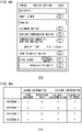
- Fig. 2 shows a data structure of a status table stored in the storage unit 314. The table already registers that the first representative fire alarm 200a, the first fire alarm 220a, and the second fire alarm 220b are included in the first group 240a and that the second representative fire alarm 200b, the third fire alarm 220c, and the fourth fire alarm 220d are included in the second group 240b. The values of battery level of the representative fire alarms 200 and the fire alarms 220 are indicated.
- Date and time information indicates the date and time when an alarm is originated. Date and time information is generated by the representative fire alarm 200 or the fire alarm 220 and is included in the alarm information. Reference is made back to Fig. 1 .
- the processing unit 330 causes the first communication unit 310 to periodically transmit a check signal for checking connection to each of the representative fire alarms 200 and the fire alarms 220.
- the representative fire alarm 200 and the fire alarm 220 Upon receiving the check signal, the representative fire alarm 200 and the fire alarm 220 transmit a reply signal for indicating a reply to the check signal to the controller 300.
- the reply signal also includes the sensor identification information. Transmission of a check signal to and reception of a reply signal from the fire alarm 220 are performed via the representative fire alarm 200.
- the first communication unit 310 of the controller 300 Upon receiving a reply signal, the first communication unit 310 of the controller 300 outputs the reply signal to the processing unit 330.
- the processing unit 330 determines that it is possible to communicate with the representative fire alarm 200 or the fire alarm 220 receiving the reply signal in response to the check signal. Meanwhile, the processing unit 330 determines that it is not possible to communicate with the representative fire alarm 200 or the fire alarm 220 for which a reply signal in response to a check signal is not received for a predetermined period of time.
- the processing unit 330 stores, for each sensor identification information, communication status information indicating whether communication is enabled or disabled. In the status table shown in Fig. 2 , " 1 " in the "acquisition failure" field of the "communication status information” means communication is disabled, and "0" in the "acquisition failure” field of the "communication status information” means communication is enabled.
- the screens for displaying information related to the representative fire alarm 200 and the fire alarm 220 will be described in the order of (1) the screen displayed on the mobile terminal apparatus 500, (2) the screen for push notice displayed on the mobile terminal apparatus 500, (3) the screen displayed on the controller 300, and (4) the screen for push notification displayed on the controller 300. In this embodiment, at least one of these screens may be displayed.
- the second communication unit 312 performs, for example, wireless communication or communication by wire and is connected to the server 440 via the router 400 and the network 420.
- wireless local area network LAN
- the second communication unit 312 transmits the changed information to the server 440.
- the information transmitted from the second communication unit 312 includes facility identification information for identifying the facility 100 in addition to the sensor identification information.
- the server 440 stores one of the alarm information, failure information, communication status information, and battery level for each facility identification information and sensor identification information. Through these steps, the status table in the server 440 is synchronized with the status table of the storage unit 314 with a delay of a predetermined period of time.
- the mobile terminal apparatus 500 is, for example, a smartphone, a tablet terminal apparatus, and a mobile terminal apparatus and is used by the user residing in the facility 100.
- the communication unit 510 of the mobile terminal apparatus 500 is connected to the server 440 via the network 420 by performing wireless communication.
- a mobile phone system such as long term evolution (LTE) or wireless LAN is used for wireless communication, but the embodiment is not limited thereto.
- the storage unit 514 stores a program executable in the mobile terminal apparatus 500.
- the storage unit 514 stores an application program.
- an application program capable of executing the process in the control system 1000 hereinafter, "control system application" is highlighted.
- the user operation unit 516 is exemplified by a touch panel and can receive a user operation input from a user.
- the user operation unit 516 receives a user operation input of a user
- the user operation unit 516 outputs a user operation signal determined by the user operation input to the processing unit 530.
- the display unit 518 displays a screen generated by the display control unit 542.
- the display unit 518 may be integrated with the user operation unit 516.
- the display unit 518 displays a screen including a button, and the user operation unit 516 receives a user operation input provided by a touch of the user on the button.
- the processing unit 530 is comprised of, for example, a microcomputer including a processor and a memory.
- the functions of the processing unit 530 are realized by the computer system as the processor executes the program stored in the storage unit 514.
- the processing unit 530 according to the embodiment executes the control system application.
- the screen generated by executing the control system application is displayed on the display unit 518.
- the processing unit 530 transmits a signal (hereinafter, "event information request signal”) for requesting transmission of information to the server 440 via the communication unit 510 and the network 420.
- the event information request signal includes identification information for identifying the mobile terminal apparatus 500 (hereinafter, "terminal identification information").
- the server 440 Upon receiving the event information request signal, the server 440 extracts the terminal identification information from the event information request signal. Further, the server 440 stores the correspondence between the terminal identification information and the facility identification information in advance and identifies the facility identification information from the extracted terminal identification information, based on the correspondence. The server 440 transmits the status table of the facility identification information thus identified to the mobile terminal apparatus 500 via the network 420. The status table may be included in the event information.
- the communication unit 510 of the mobile terminal apparatus 500 receives the status table from the server 440 via the network 420.
- the processing unit 530 causes the storage unit 514 to store the status table received by the communication unit 510.
- the input unit 540 of the processing unit 530 receives the information on each of the representative fire alarms 200 and the fire alarms 220 from the storage unit 514.
- the information is comprised of, for example, alarm information, failure information, communication status information, and battery level, and the alarm information includes information indicating the date and time of the alarm.
- the display control unit 542 generates a screen for displaying the information received by the input unit 540 on the display unit 518.
- Figs. 3A-3D will be used to explain the screens generated by the display control unit 542.
- Figs. 3A-3D show screens displayed on the display unit 518.
- Fig. 3A shows a screen showing representative information representative of each of the groups
- Fig. 3B shows a screen showing detailed information on one group
- Fig. 3C shows a screen for timeline showing a history of information.
- the screens shown in Figs. 3A-3C are displayed as the user uses the user operation unit 516 of the mobile terminal apparatus 500.
- Fig. 3A corresponds to a screen including the first area 628
- Fig. 3B corresponds to a screen including the second area 626
- Fig. 3C corresponds to a screen including the second area 630.
- the display control unit 542 generates a screen so that a first portion 620 and a second portion 622 are included in the first area 628 in the same screen. More specifically, the display control unit 542 generates a screen in which the first portion 620 and the second portion 622 are arranged vertically.
- the first portion 620 is a portion for showing the information related to the first group 240a
- the second portion 622 is a portion for showing the information related to the second group 240b.
- the display control unit 542 provides a first group display field 710 in the first portion 620 and shows the name "fire alarm 1" of the first representative fire alarm 200a, a first message notice 642, and a first dead battery notice 662 in the first group display field 710.
- the display control unit 542 provides a second group display field 712 in the second portion 622 and shows the name "fire alarm 2" of the second representative fire alarm 200b, a first message notice 642, and a first dead battery notice 662 in the second group display field 712.
- the detail of the representative information on the first group 240a and the representative information on the second group 240b such as the first message notice 642, the first dead battery notice 662 will be described later.
- a touch on the display portion of the "first alarm 1" in the first portion 620 by the user causes the user operation unit 516 to receive an instruction for transition to the screen showing the detailed information on the first group 240a.
- the display control unit 542 generates a screen as shown in Fig. 3B so that the first portion 620 is included in the second area 626.
- the display control unit 542 provides a first representative fire alarm display field 700, a first fire alarm display field 702, and a second fire alarm display field 704 in the first portion 620.
- the name "fire alarm 1" of the first representative fire alarm 200a is shown in the first representative fire alarm display field 700
- the name "living/fire alarm” of the first fire alarm 220a is shown in the first fire alarm display field 702.
- the name “dining/fire alarm” of the second fire alarm 220b is shown in the second fire alarm display field 704.
- the display control unit 542 When at least one of the alarm information, failure information, and communication status information related to the first representative fire alarm 200a of the first group 240a is received, the display control unit 542 causes the second message notice 640 to be displayed in the first representative fire alarm display field 700 in the first portion 620. When at least one of the alarm information, failure information, and communication status information related to the first fire alarm 220a of the first group 240a is received, the display control unit 542 causes the second message notice 640 to be displayed in the first fire alarm display field 702 in the first portion 620.
- the display control unit 542 When at least one of the alarm information, failure information, and communication status information related to the second fire alarm 220b of the first group 240a is received, the display control unit 542 causes the second message notice 640 to be displayed in the second fire alarm display field 704 in the first portion 620. When none of the alarm information, failure information, and communication status information is received, on the other hand, the display control unit 542 does not cause the second message notice 640 to be displayed.
- the second message notice 640 is a notice to communicate the alarm information, failure information, and communication status information related to the corresponding representative fire alarm 200, the fire alarm 220 is received.
- the second message notice 640 indicates "fire incident", “forced alarm sounding", “failure/speaker disconnection”, and "10-year-elapse notice", respectively.
- the second message notice 640 in the first representative fire alarm display field 700 indicates "fire incident", showing that fire incident in the alarm information related to the first representative fire alarm 200a is received.
- the second message notice 640 in the first fire alarm display field 702 indicates "failure/speaker disconnection", showing that failure/disconnection in the failure information related to the first fire alarm 220a is received. Further, the second message notice 640 in the second fire alarm display field 704 indicates "10-year-elapse notice", showing that elapse of 10 years in the failure information related to the second fire alarm 220b is received.
- the display control unit 542 maintains a threshold value that should be compared with the battery level. For example, the display control unit 542 maintains a first threshold value and a second threshold value (first threshold value>second threshold value). By way of example, the first threshold value is “20%”, and the second threshold value is "10%”. When the battery level is lower than the first threshold value and equal to or higher than the second threshold value, the display control unit 542 determines that battery is consumed. When the battery level is lower than the second threshold value, the display control unit 542 determines that the battery is dead.
- the display control unit 542 causes a second battery consumption notice (not shown) to be displayed in the first portion 620 in association with the representative fire alarm 200, the fire alarm 220 for which it is determined that the battery is consumed and causes a second dead battery notice 660 to be displayed in the first portion 620 in association with the representative fire alarm 200, the fire alarm 220 for which it is determined that the battery is dead.
- the second battery consumption notice is a notice for indicating that the battery is consumed
- the second dead battery notice 660 is a notice for indicating that the battery is dead.
- the battery level of the first representative fire alarm 200a and the second fire alarm 220b is lower than the second threshold value so that the second dead battery notice 660 is shown in the first representative fire alarm display field 700 and the second fire alarm display field 704.
- the battery level of the first fire alarm 220a is equal to or higher than the first threshold value so that the second battery consumption notice or the second dead battery notice 660 is not shown in the first fire alarm display field 702.
- the second battery consumption notice and the second dead battery notice 660 are generically referred to as "second battery level notice", and it can be said that the second battery level notice is a notice for indicating that the battery level is lower than a threshold value.
- a user's touch on the display portion for the "fire alarm 2" in the second portion 622 of Fig. 3A causes the user operation unit 516 to receive an instruction for transition to the screen showing the detailed information on the second group 240b. Illustration of this screen will be omitted, but the display control unit 542 generates a screen similar to that of Fig. 3B . In that screen, the second portion 622 is included in the second area 626.
- the display control unit 542 provides a second representative fire alarm display field, a third fire alarm display field, and a fourth fire alarm display field in the second portion 622.
- the name "fire alarm 2" of the second representative fire alarm 200b is shown in the second representative fire alarm display field
- the name of the third fire alarm 220c is shown in the third fire alarm display field
- the name of the fourth fire alarm 220d is shown in the fourth fire alarm display field.
- the second message notice 640, the second dead battery notice 660, etc. are shown as already described.
- the first portion 620 of the second area 626, the second portion 622 of the second area 626, and the first area 628 are included in mutually different screens. Further, it is possible to make a transition from the screen including the first area 628 to the screen including the first portion 620 of the second area 626, and it is also possible to make a transition to the screen including the second portion 622 of the second area 626.
- the display control unit 542 shows at least one second message notice 640 in the first portion 620 of the second area 626 shown in Fig. 3B
- the display control unit 542 causes the first message notice 642 to be displayed in the first group display field 710.
- the display control unit 542 does not show the second message notice 640 in the first portion 620 of the second area 626 shown in Fig. 3B
- the display control unit 542 does not cause the first message notice 642 to be displayed in the first group display field 710.
- the second message notice 640 is shown in the first representative fire alarm display field 700, the first fire alarm display field 702, and the second fire alarm display field 704 in the first portion 620 of the second area 626. Therefore, the first message notice 642 is shown in the first group display field 710.
- the first representative fire alarm display field 700, the first fire alarm display field 702, and the second fire alarm display field 704 in the first portion 620 of the second area 626 differ in the content of the second message notice 640.
- This is equivalent to the reception of fire incident, failure/disconnection, and elapse of 10 years in association with the first representative fire alarm 200a and the fire alarms 220 included in the first group 240a.
- the display control unit 542 assigns the highest degree of priority to fire incident and assigns progressively lower degrees of priority to operation test, failure/disconnection, and elapse of 10 years.
- the display control unit 542 assigns the lowest degree of priority to acquisition failure.
- the display control unit 542 selects the information with the highest degree of priority. In this case, fire incident is selected.
- the display control unit 542 causes "fire incident" thus selected to be displayed as the first message notice 642 in the first group display field 710 in the first portion 620 of the first area 628 of Fig. 3A .
- the first message notice 642 is a notice to indicate the presence of information with a higher degree of priority when a plurality of items of information are received.
- the display control unit 542 When the display control unit 542 shows at least one second battery level notice in the first portion 620 of the second area 626 shown in Fig. 3B , the display control unit 542 causes the first battery level notice for indicating the presence of at least one battery level notice to be displayed in the first group display field 710.
- the first battery consumption notice is shown in the first group display field 710.
- the second dead battery notice 660 is shown in the first portion 620 of the second area 626
- the first dead battery notice 662 is shown in the first group display field 710.
- the second battery level notice shown in the first portion 620 of the second area 626 is identical to the first battery level notice shown in the first group display field 710.
- the first dead battery notice 662 is shown in the first group display field 710.
- the display control unit 542 does not show at least one second battery level notice in the first portion 620 of the second area 626, on the other hand, the display control unit 542 does not cause the first battery level notice to be displayed in the first group display field 710.
- the second dead battery notice 660 is shown in the first representative fire alarm display field 700 and the second fire alarm display field 704 in the first portion 620 of the second area 626, and so the first dead battery notice 662 is shown in the first group display field 710.
- the first message notice 642 and the second battery level notice that can be displayed in the first group display field 710 are the representative information on the first group 240a.
- the representative information on the second group 240b is shown in the second group display field 712, and a description thereof is omitted since it is similar to the representative information on the first group 240a.
- Fig. 3C shows s a screen for timeline generated by the display control unit 542.
- the screen for timeline is a screen that includes the first portion 620 in the second area 630 and is a screen that shows a history of information related to one of the representative fire alarm 200 and the fire alarms 220.
- a history of information related to the first representative fire alarm 200a is shown by way of example.
- a transition to the timeline screen like this can be made from the screen that shows the detailed information on one group, i.e., from the screen of Fig. 3B showing the second area 626.
- a transition to the timeline screen may be made from the screen showing the representative information on each group, i.e., from the screen of Fig. 3A showing the first area 628.
- the first portion 620 of the second area 630 of Fig. 3C shows all second message notices 644 related to the first representative fire alarm 200a.
- two second message notices 644 are shown by way of example.
- the two second message notices 644 indicate "fire incident" and "10-year-elapse notice".
- the display control unit 542 selects the information with the highest degree of priority in accordance with the degree of priority described above. Further, the display control unit 542 displays a message corresponding to the selected information in the second message notice 640 in the first representative fire alarm display field 700 of Fig. 3B . Still further, when the display control unit 542 determines that the battery of the first representative fire alarm 200a is consumed or dead, the display control unit 542 shows a history of the first representative fire alarm 200a thus determined in the timeline screen.
- the display control unit 542 equally generates a screen for timeline similar to that of Fig. 3C in association with the first fire alarm 220a and the second fire alarm 220b included in the first group 240a. Further, the display control unit 542 equally generates a screen for timeline in association with the second representative fire alarm 200b, the third fire alarm 220c and the fourth fire alarm 220d included in the second group 240b.
- the screen for timeline is a screen that includes the second portion 622 in the second area 630 and is a screen that shows a history of information related to one of the representative fire alarm 200 and the fire alarms 220.
- Fig. 3D will be described later, and reference is made back to Fig. 1 .
- the representative fire alarm 200 communicates directly with the controller 300, but the fire alarm 220 communicates with the controller 300 via the representative fire alarm 200. Therefore, when communication of the representative fire alarm 200 is disabled, communication of the fire alarm 220 connected to the representative fire alarm 200 is also disabled. When communication of the fire alarm 220 is disabled, on the other hand, the other fire alarms 220 and the representative fire alarm 200 are not affected. In other words, the impact from disabled communication of the representative fire alarm 200 is larger than the impact from disabled communication of the fire alarm 220.
- the display control unit 542 may display that communication with the representative fire alarm 200 is disabled on the display unit 518 in addition to or apart from the display of "acquisition failure" in the first message notice 642 and the second message notice 640.
- the display control unit 542 causes a setting screen in the control system application to be displayed on the display unit 518.
- Figs. 4A-4B show a summary of the setting made in the mobile terminal apparatus 500.
- Fig. 4A shows a setting screen displayed on the display unit 518.
- each of a plurality of items can be set to "ON” or “OFF”.
- "operation/maintenance notice” and “operation test notice” of the "fire alarm” can be set to "ON” or “OFF” in this embodiment.
- Event information includes information on fire incident of fire incident information, operation test of fire incident information, failure/disconnection of failure information, and elapse of 10 years of failure information. Event information may include at least one of these items of information.
- operation/maintenance notice in Fig. 4A , a push notice for communicating fire incident, failure/disconnection, elapse of 10 years is enabled or disabled.
- operation/maintenance notice is set to "ON”.
- operation/maintenance is set to "OFF”.
- a push notice for communicating that an operation test is available is enabled or disabled in “operation test notice”. The user uses the user operation unit 516 to set "ON” or "OFF”.
- the setting unit 544 enables or disables a notice for communicating that the event information is available when the event information is received, by receiving a user operation in the user operation unit 516.
- the setting unit 544 enables or disables a notice for communicating fire incident, failure/disconnection, elapse of 10 years and, separately, enables or disables a notice for communicating that an operation test is available.
- Fig. 4B shows a pattern of setting made in the setting unit 544. In this case, ON is indicated by "1", and OFF is indicated by "0".
- Pattern 1 is a case where "operation/maintenance notice” and “operation test notice” are set to OFF
- pattern 2 is a case where "operation test notice” is set to ON, and "operation/maintenance notice” is set to OFF
- Pattern 3 is a case where "operation/maintenance notice” is set to ON and “operation test notice” is set to OFF
- Pattern 4 is a case where "operation/maintenance notice” and "operation test notice” are set to ON. Reference is made back to Fig. 1 .
- the setting unit 544 causes the communication unit 510 to transmit the setting information indicating the setting result and the terminal identification information to the server 440.
- the server 440 receives the setting information and the terminal identification information from the mobile terminal apparatus 500, the server 440 stores the combination.
- the second communication unit 312 of the controller 300 transmits, at a point of time when any of the alarm information, failure information, communication status information, and battery level stored in the storage unit 314 is changed, the changed information to the server 440.
- the alarm information corresponds to fire incident and operation test
- the failure information corresponds to failure/disconnection and elapse of 10 years.
- These items of information constitute the event information. It can therefore be said that the second communication unit 312 transmits changed event information to the server 440 when one of event information items is changed.
- the server 440 receives the event information from the controller 300. It can be said that the input (not shown) is configured to receive the event information from the representative fire alarm 200 or the representative fire alarm 200. Upon receiving the event information, the server 440 extracts the facility identification information from the event information. Further, the server 440 identifies the terminal identification information from the extracted facility identification information, based on the correspondence between the terminal identification information and the facility identification information. The server 440 refers to the setting information associated with the terminal identification information thus identified and checks the information included in the event information to see whether there is any information for which a notice is set to ON. When the setting information is of pattern 3, for example, the server 440 checks whether the event information includes fire incident or failure/disconnection or elapse of 10 years. If it is not included, the server 440 terminates the process for push notice. When it is included, on the other hand, the server 440 transmits the event information to the mobile terminal apparatus 500 identified by the terminal identification information via the network 420.
- the communication unit 510 of the mobile terminal apparatus 500 receives the event information from the server 440.
- the display control unit 542 displays a notice showing the event information on the display unit 518.
- the notice is shown like the second message notice 640.
- Fig. 3D shows a screen for push notice displayed on the display unit 518.
- a notice window 680 is displayed, and a notice message is shown in the notice window 680.
- the event information comprises fire incident so that a message "fire incident" is shown.
- the server 440 includes a display control unit (not shown).
- the display control unit causes, when the input unit receives the event information, the display unit 518 of the mobile terminal apparatus 500 to display a notice.
- the display control unit causes the display unit 518 of the mobile terminal apparatus 500 to display a history of event information received by the input unit, i.e., the timeline, through the process described in (1), regardless of whether a notice is enabled or disabled by the setting unit 544 of the mobile terminal apparatus 500.
- the provision of the display control unit in the server 440 and the provision of the setting unit 544 in the mobile terminal apparatus 500 cause the server 440 and the mobile terminal apparatus 500 to constitute a display system.
- Screens displayed on the display unit 518 of the mobile terminal apparatus 500 have been described above. These screens may be displayed on the display unit 318 of the controller 300.
- the screen displayed on the display unit 518 has been assumed to be a screen more elongated in the vertical direction than in the horizontal direction. In this case, however, a screen more elongated in the horizontal direction than in the vertical direction is assumed as the screen displayed on the display unit 318.
- the input unit 340 executes a process similar to that of the input unit 540.
- the display control unit 342 generates a screen for displaying the information received by the input unit 340 on the display unit 318.
- Figs. 5A-5D will be used to explain the screen generated by the display control unit 342.
- Figs. 5A-5D show screens displayed on the display unit 318.
- Fig. 5A shows a screen showing representative information representative of each of the groups
- Fig. 5B shows a screen showing detailed information on one group
- Fig. 5C shows a screen for timeline showing a history of information.
- Figs. 5A-5C correspond to Figs. 3A-3C , respectively.
- Fig. 5A corresponds to a screen including the first area 628
- Fig. 5B corresponds to a screen including the second area 626
- Fig. 5C corresponds to a screen including the second area 630.
- the display control unit 542 generates a screen so that the first portion 620 and the second portion 622 are included in the first area 628 in the same screen. More specifically, the display control unit 542 generates a screen in which the first portion 620 and the second portion 622 are arranged horizontally. Provision of the first group display field 710 in the first portion 620 and the provision of the second group display field 712 in the second portion 622, and the content displayed in the first group display field 710 and the second group display field 712 are as shown in Fig. 3A so that a description thereof is omitted.
- the display control unit 342 generates a screen in which the first portion 620 is included in the second area 626. Provision of the first representative fire alarm display field 700, the first fire alarm display field 702, and the second fire alarm display field 704 in the first portion 620 and the content displayed in the first representative fire alarm display field 700, the first fire alarm display field 702, and the second fire alarm display field 704 are as shown in Fig. 3B so that a description thereof is omitted.
- the display control unit 342 generates a screen for history in which the first portion 620 is included in the second area 630. A transition to the screen for history can be made from a screen showing the representative information on each group or a screen showing the detailed information on one group. The content displayed in the screen for history is similar to that of Fig. 3C so that a description thereof is omitted.
- the display control unit 342 causes the display unit 318 to display a setting screen.
- Figs. 6A-6B show a summary of the setting made in the controller 300.
- Fig. 6A shows a setting screen displayed on the display unit 318.
- alarm notice can be set to "ON” or "OFF”.
- "operation/maintenance notification” and "operation test notice” are not set. In other words, a push notice for communicating fire incident, operation test, failure/disconnection, and elapse of 10 years is enabled or disabled.
- the user uses the user operation unit 316 to set "ON” or "OFF”.
- the setting unit 344 enables or disables a notice for communicating that the event information is available when the event information is received, by receiving a user operation in the user operation unit 316.
- the setting unit 344 enables or disables a notice for communicating that the event information aggregating fire incident, failure/disconnection, and elapse of 10 years is available.
- Fig. 6B shows a pattern of setting made in the setting unit 344. In this case, ON is indicated by "1", and OFF is indicated by "0". Pattern 1 is a case where alarm notice is set to OFF, and pattern 2 is a case where alarm notice is set to ON. Reference is made back to Fig. 1 . When either pattern 1 or pattern 2 is set, the setting unit 344 stores the setting information indicating the setting result in the storage unit 314.
- the input unit 340 receives the event information from the representative fire alarm 200 or the fire alarm 220 via the first communication unit 310.
- the display control unit 342 refers to the setting information associated with the terminal identification information stored in the storage unit 314.
- the display control unit 342 terminates the process for push notice.
- the display control unit 342 activates push notification. More specifically, the display control unit 342 displays a notice indicating the event information on the display unit 318.
- the notice is shown like the second message notice 640.
- Fig. 5D shows a screen for push notice displayed on the display unit 318. A notice window 680 is displayed, and a notice message is shown in the notice window 680.
- the event information comprises fire incident so that a message "fire incident" is shown.
- the display control unit when a notice is enabled by the setting unit 344, the display control unit causes, when the input unit 340 receives the event information, the display unit 318 to display a notice. Meanwhile, the display control unit 342 causes the display unit 318 to display a history of event information received by the input unit 340, i.e., the timeline, regardless of whether a notice is enabled or disabled by the setting unit 344.
- the provision of the input unit 340, the display control unit 342, and the setting unit 344 in one controller 300 causes the controller 300 to constitute a display system.
- the device, the system, or the entity that executes the method according to the disclosure is provided with a computer.
- the computer is comprised of a processor that operates in accordance with the program as a main hardware feature.
- the disclosure is non-limiting as to the type of the processor so long as the function is realized by running the program.
- the processor is comprised of one or a plurality of electronic circuits including a semiconductor integrated circuit (IC) or a large-scale integration (LSI).
- the plurality of electronic circuits may be integrated in one chip or provided in a plurality of chips.
- the plurality of chips may be aggregated in one device or provided in a plurality of apparatuses.
- the program is recorded in a non-transitory recording medium such as a computer-readable ROM, optical disk, and hard disk drive.
- the program may be stored in a recording medium in advance or supplied to a recording medium via wide area communication network including the Internet.
- Fig. 7 is a sequence chart showing a display procedure executed by the control system 1000.
- the mobile terminal apparatus 500 performs the push notice setting (S50).
- the mobile terminal apparatus 500 transmits the setting information to the server 440 (S52).
- the server 440 stores the setting information (S54).
- the fire alarm 220 detects the occurrence of an event (S56).
- the fire alarm 220 transmits the event information to the controller 300 (S58).
- the controller 300 transmits the event information to the server 440 (S60).
- the server 440 determines whether to activate push notification based on the setting information (S62). When the server 440 determines to activate push notification, the server 440 transmits the event information to the mobile terminal apparatus 500 (S64).
- the mobile terminal apparatus 500 displays a notice (S66).
- Fig. 8 is a sequence chart showing another display procedure executed by the control system 1000.
- the controller 300 performs the push notice setting (S10).
- the fire alarm 220 detects the occurrence of an event (S12).
- the fire alarm 220 transmits the event information to the controller 300 (S14).
- the controller 300 determines whether to activate push notification based on the setting information (S16). When the controller 300 determines to activate push notification, the controller 300 displays a notice (S18).
- a notice when a notice is enabled in the setting for enabling or disabling a notice for communicating that event information is available when the event information is received, a notice is displayed when the event information is received. Therefore, a notice can be displayed when a notice is necessary.
- a notice is disabled in the setting for enabling or disabling a notice for communicating that event information is available when the event information is received, a notice is not displayed when the event information is received. Therefore, it is ensured that a notice is not displayed when a notice is not necessary.
- the system switches to display or not to display a notice depending on the setting so that the timing of display of a notice can be adjusted. Further, a notice is displayed in a history of event information regardless of whether a notice is enabled or disabled. Therefore, the event information can be displayed even when a notice is disabled. Further, the system switches to display a notice immediately or display it in a history, depending on the setting. Therefore, the timing of display of a notice can be adjusted.
- the setting unit 344 enables or disables a notice for communicating that the event information aggregating information on fire incident, information on operation test, and information on maintenance is available. Therefore, the setting can be simplified.
- the setting unit enables or disables a notice for communicating information on fire incident and information on maintenance and, separately, enables or disables a notice for communicating that information on operation test is available. Therefore, detailed setting can be made.
- the input unit 340, the setting unit 344, and the display control unit 342 are included in one apparatus so that the process is completed in one apparatus. Further, the input unit and the display control unit are included in the server 440, and the setting unit 544 is included in the mobile terminal apparatus 500 so that the processing volume in the mobile terminal apparatus 500 can be reduced.
- a display system (300, 400, 500) includes: an input unit (340) that is configured to receive event information from a fire alarm (200, 220) provided in a facility (100); a setting unit (344, 544) that enables or disables a notice for communicating that the event information is available when the input unit (340) receives the event information; and a display control unit (342) that causes a display unit (318, 518) to display the notice when the setting unit (344, 544) enables a notice and when the input unit (340) receives the event information.
- the display control unit (342) causes the display unit (318, 518) to display a history of the event information received by the input unit (340) regardless of whether a notice is enabled or disabled by the setting unit (344, 544).
- the event information may include at least one of information on fire incident, information on operation test, and information on maintenance.
- the setting unit (344) enables or disables a notice for communicating that the event information, which aggregates the information on fire incident, the information on operation test, and the information on maintenance, is available.
- the event information may include at least one of information on fire incident, information on operation test, and information on maintenance.
- the setting unit (544) enables or disables a notice for communicating that the information on fire incident and the information on maintenance are available and, separately, enables or disables a notice for communicating that the information on operation test is available.
- the input unit (340), the setting unit (344), and the display control unit (342) are included in one apparatus.
- the input unit and the display control unit are included in a server (440), and the setting unit (544) is included in an information terminal apparatus (500) configured to communicate with the server (440).
- Another embodiment of the present disclosure relates to a display method.
- The includes: receiving event information from a fire alarm (200, 220) provided in a facility (100); enabling or disabling a notice for communicating that the event information is available when event information is received; and causing a display unit (318, 518) to display the notice when a notice is enabled and when the event information is received.
- the senor is assumed to be the representative fire alarm 200 and the fire alarm 220.
- the sensor may be a gas alarm etc., or different types of alarms may coexist. According to this variation, the flexibility in configuration can be improved.
- the timing of display of a notice can be adjusted.
Abstract
Description
- The present disclosure relates to display technology and, more particularly, to a display system, display method, and program.
- Fire alarms are provided in a facility such as building. When the fire alarm detects a fire, the fire alarm transmits a fire signal to a server. A mobile terminal apparatus communicates with the server and displays support information regarding the fire (see, for example, patent literature 1).
- [Patent Literature 1]
JP Patent 6240744 - Displaying a notification from a fire alarm in the mobile terminal apparatus makes it possible to check the notification. However, there are cases in which the notification is desired to be checked immediately and cases in which the notification cannot be checked immediately. It is therefore preferred to adjust the timing to check a notification.
- The present disclosure addresses the above-described issue, and a purpose thereof is to provide a technology of adjusting the timing of display of a notice.
- A display system according to an embodiment of the present disclosure includes: an input unit that is configured to receive event information from a fire alarm provided in a facility; a setting unit that enables or disables a notice for communicating that the event information is available when the input unit receives the event information; and a display control unit that causes a display unit to display the notice when the setting unit enables a notice and when the input unit receives the event information.
- Another embodiment of the present disclosure relates to a display method. The method includes: receiving event information from a fire alarm provided in a facility; enabling or disabling a notice for communicating that the event information is available when event information is received; and causing a display unit to display the notice when a notice is enabled and when the event information is received.
- Optional combinations of the aforementioned constituting elements, and implementations of the present disclosure in the form of devices, systems, computer programs, recording mediums recording computer programs, etc. may also be practiced as additional modes of the present invention.
- According to the present disclosure, the timing of display of a notification can be adjusted.
-
-
Fig. 1 shows a configuration of a control system according to the embodiment; -
Fig. 2 shows a data structure of a status table stored in the storage unit ofFig. 1 ; -
Figs. 3A-3D show screens displayed on the display unit ofFig. 1 ; -
Figs. 4A-4B show a summary of the setting made in the mobile terminal apparatus ofFig. 1 ; -
Figs. 5A-5D show screens displayed on the display unit ofFig. 1 ; -
Figs. 6A-6B show a summary of the setting made in the controller ofFig. 1 ; -
Fig. 7 is a sequence chart showing a display procedure executed by the display system ofFig. 1 ; and -
Fig. 8 is a sequence chart showing another display procedure executed by the control system ofFig. 1 . - A summary of the embodiment will be given before describing the embodiment of the present disclosure in specific details. The embodiment relates to a control system for displaying information related to each of a plurality of sensors provided in a facility such as a house. The plurality of sensors are exemplified by fire alarms. The plurality of fire alarms are connected to a controller provided in the facility and transmit alarm information to a controller when a fire is detected and transmits failure information to the controller when a failure is detected. Further, the plurality of fire alarms are driven by batteries and transmit a battery level to the controller. The controller is connected to a server outside the facility via a network and transmits the alarm information, failure information, and battery level (hereinafter, generically referred to as "information") to the server. The server can be accessed from an information terminal apparatus such as a smartphone. The information terminal apparatus or the controller is a display apparatus and can display each of the plurality of items of information. Meanwhile, the user may want to check a notice of information immediately or cannot check a notice of information because the user is attending a meeting, for example. In order to adjust the timing of display of a notice, the embodiment is configured to set whether to display a notice on the screen of the display apparatus.
-
Fig. 1 shows a configuration of acontrol system 1000. Thecontrol system 1000 includes a first representative fire alarm 200a and a secondrepresentative fire alarm 200b, which are generically referred to asrepresentative fire alarms 200, afirst fire alarm 220a, asecond fire alarm 220b, a third fire alarm 220c, and a fourth fire alarm 220d, which are generically referred to asfire alarms 220, acontroller 300, arouter 400, anetwork 420, aserver 440, and amobile terminal apparatus 500. The number ofrepresentative fire alarms 200 is assumed to be but not limited to "2", and the number offire alarms 220 is assumed to be but not limited to "4". - The
representative fire alarm 200 includes adetection unit 202, acontrol unit 204, and acommunication unit 206. Thecontroller 300 includes afirst communication unit 310, asecond communication unit 312, astorage unit 314, auser operation unit 316, adisplay unit 318, and aprocessing unit 330. Theprocessing unit 330 includes aninput unit 340, adisplay control unit 342, and asetting unit 344. Themobile terminal apparatus 500 includes acommunication unit 510, astorage unit 514, auser operation unit 516, adisplay unit 518, and aprocessing unit 530. Theprocessing unit 530 includes aninput unit 540, adisplay control unit 542, and asetting unit 544. - The
representative fire alarm 200, thefire alarm 220, thecontroller 300, and therouter 400 are provided in thefacility 100. Thenetwork 420 and theserver 440 are provided outside thefacility 100. Thefacility 100 is a building subject to control by thecontrol system 1000 and is exemplified by an independent housing. Thefacility 100 is not limited to an independent housing and may be a housing in a multi-unit apartment building, an office building, a commercial facility, etc. Therepresentative fire alarm 200 and thefire alarm 220 are provided as a sensor for detecting the occurrence of a fire in each of a plurality of rooms in thefacility 100. Therepresentative fire alarm 200 and thefire alarm 220 communicate wirelessly with thecontroller 300. For example, specified low power radio is used for wireless communication, but the embodiment is not limited to this. The fire alarms may communicate by wire. - Wireless communication between the
representative fire alarm 200, thefire alarm 220 and thecontroller 300 will be described in further detail. Therepresentative fire alarms 200 and thefire alarms 220 are organized into afirst group 240a and asecond group 240b, which are generically referred to as groups 240. Thefirst group 240a includes the first representative fire alarm 200a, thefirst fire alarm 220a, and thesecond fire alarm 220b. Thesecond group 240b includes the secondrepresentative fire alarm 200b, the third fire alarm 220c, and the fourth fire alarm 220d. In other words, one group includes onerepresentative fire alarm 200 and one ormore fire alarm 220. - The
representative fire alarm 200 communicates wirelessly with thecontroller 300 by using the first frequency band such as the 926 MHz band and also communicates wirelessly with thefire alarm 220 by using the second frequency band such as the 426 MHz band. Meanwhile, thefire alarm 220 communicates wirelessly with therepresentative fire alarm 200 by using the second frequency band such as the 426 MHz band but does not directly communicate wirelessly with thecontroller 300. Thefire alarm 220 communicates wirelessly with thecontroller 300 via therepresentative fire alarm 200. Therefore, therepresentative fire alarm 200 also has the function of relaying wireless communication between thecontroller 300 and thefire alarm 220 in addition to the function of communicating wirelessly with thecontroller 300. - The
representative fire alarm 200 and thefire alarm 220 differ in the availability of the relaying function and are otherwise identical in the function of detecting a fire, etc. Therefore, therepresentative fire alarm 200 may be referred to as thefire alarm 220 when a description is given of a feature other than wireless communication. - The
representative fire alarm 200 is a sensor capable of detecting the occurrence of a fire in a room, etc. of thefacility 100. Thedetection unit 202 of therepresentative fire alarm 200 detects the occurrence of a fire by detecting the smoke or detecting the heat. In the case of smoke-based detection for detecting the smoke, the occurrence of a fire is detected as the smoke enters therepresentative fire alarm 200, and the light of the light emitting diode is reflected by particles of the smoke and reaches the light receiving unit. In the case of heat-based detection for detecting the heat, the occurrence of a fire is detected as the heat sensitive element reaches a certain temperature. When thedetection unit 202 detects the occurrence of a fire, thecontrol unit 204 outputs a sound for communicating a fire incident from a speaker (not shown) and generates alarm information for communicating the fire incident. The alarm information includes at least one of fire incident and operation test. Fire incident indicates the occurrence of a fire, and operation test indicates a forced sounding of an alarm by an operation test. Thecommunication unit 206 transmits the alarm information to thecontroller 300 in the first frequency band. In that process, thecommunication unit 206 may transmit the alarm information to thefire alarm 220 in the second frequency band. - The
control unit 204 detects a failure or a speaker disconnection in therepresentative fire alarm 200. A publicly known technology may be used for the detection, and a description thereof is omitted. Thecontrol unit 204 further includes a timekeeping function and measures the period of time since the manufacturing or since the previous maintenance. When a failure or speaker disconnection is detected, thecontrol unit 204 generates failure information including failure/disconnection, which indicates a failure or speaker disconnection, and generates failure information including elapse of 10 years, indicating that 10 years have elapsed, when it is detected that 10 years have elapsed. The failure information may include failure/disconnection and elapse of 10 years. Thecommunication unit 206 transmits the failure information to thecontroller 300 in the first frequency band. - Further, the
detection unit 202 detects the level of the battery that drives therepresentative fire alarm 200. A publicly known technology may be used for the detection of a battery level, and a description thereof is omitted. The battery levels of, for example, 80%, 50%, etc. are shown. When the battery level detected by thedetection unit 202 changes, thecontrol unit 204 cause thecommunication unit 206 to transmit the battery level to thecontroller 300 in the first frequency band. The battery level may be transmitted only when it changes by a predetermined amount (e.g., 5%) instead of ever time the battery level changes. - The configuration of the
fire alarm 220 is similar to the configuration of therepresentative fire alarm 200, but the communication unit 206 (not shown) of thefire alarm 220 transmits the alarm information, failure information, and battery level in the second frequency band. The destination of the alarm information and failure information is therepresentative fire alarm 200 but may includeother fire alarms 220. The destination of the battery level is therepresentative fire alarm 200. - When the
communication unit 206 of therepresentative fire alarm 200 receives the alarm information, failure information, and battery level in the second frequency band from thefire alarm 220 in the relaying process, thecommunication unit 206 transmits the alarm information, failure information, and battery level to thecontroller 300 in the first frequency band. Further, therepresentative fire alarm 200 or thefire alarm 220 may output a sound for communicating the occurrence of a fire from a speaker (not shown) upon receiving the alarm information including fire incident. - As described above, the
first communication unit 310 of thecontroller 300 is compatible with, for example, specified low power radio and receives the alarm information and failure information from therepresentative fire alarm 200. The alarm information includes identification information (hereinafter, "sensor identification information") for identifying therepresentative fire alarm 200 or thefire alarm 220 transmitting the information. Thefirst communication unit 310 outputs the alarm information and failure information to theprocessing unit 330. Thefirst communication unit 310 receives the battery level from therepresentative fire alarm 200. The battery level also includes the sensor identification information. Thefirst communication unit 310 outputs the battery level of theprocessing unit 330. - The
processing unit 330 stores the alarm information, failure information, and battery level received in thestorage unit 314. Thestorage unit 314 stores the alarm information, failure information, and battery level for each sensor identification information. This is equivalent to storing the alarm information, failure information, and battery level for each sensor.Fig. 2 shows a data structure of a status table stored in thestorage unit 314. The table already registers that the first representative fire alarm 200a, thefirst fire alarm 220a, and thesecond fire alarm 220b are included in thefirst group 240a and that the secondrepresentative fire alarm 200b, the third fire alarm 220c, and the fourth fire alarm 220d are included in thesecond group 240b. The values of battery level of therepresentative fire alarms 200 and thefire alarms 220 are indicated. When the alarm information including fire incident is received, "1" is entered in "fire incident". When alarm information including fire incident is not received, "0" is entered in "fire incident". The same is true of operation test in the alarm information, failure/disconnection and elapse of 10 years in the failure information. Date and time information indicates the date and time when an alarm is originated. Date and time information is generated by therepresentative fire alarm 200 or thefire alarm 220 and is included in the alarm information. Reference is made back toFig. 1 . - The
processing unit 330 causes thefirst communication unit 310 to periodically transmit a check signal for checking connection to each of therepresentative fire alarms 200 and thefire alarms 220. Upon receiving the check signal, therepresentative fire alarm 200 and thefire alarm 220 transmit a reply signal for indicating a reply to the check signal to thecontroller 300. The reply signal also includes the sensor identification information. Transmission of a check signal to and reception of a reply signal from thefire alarm 220 are performed via therepresentative fire alarm 200. - Upon receiving a reply signal, the
first communication unit 310 of thecontroller 300 outputs the reply signal to theprocessing unit 330. Through these steps, theprocessing unit 330 determines that it is possible to communicate with therepresentative fire alarm 200 or thefire alarm 220 receiving the reply signal in response to the check signal. Meanwhile, theprocessing unit 330 determines that it is not possible to communicate with therepresentative fire alarm 200 or thefire alarm 220 for which a reply signal in response to a check signal is not received for a predetermined period of time. Theprocessing unit 330 stores, for each sensor identification information, communication status information indicating whether communication is enabled or disabled. In the status table shown inFig. 2 , "1 " in the "acquisition failure" field of the "communication status information" means communication is disabled, and "0" in the "acquisition failure" field of the "communication status information" means communication is enabled. - Hereinafter, the screens for displaying information related to the
representative fire alarm 200 and thefire alarm 220 will be described in the order of (1) the screen displayed on the mobileterminal apparatus 500, (2) the screen for push notice displayed on the mobileterminal apparatus 500, (3) the screen displayed on thecontroller 300, and (4) the screen for push notification displayed on thecontroller 300. In this embodiment, at least one of these screens may be displayed. - The
second communication unit 312 performs, for example, wireless communication or communication by wire and is connected to theserver 440 via therouter 400 and thenetwork 420. For example, wireless local area network (LAN) is used for wireless communication, but the embodiment is not limited thereto. When any of the alarm information, failure information, communication status information, and battery level stored in thestorage unit 314 is changed, thesecond communication unit 312 transmits the changed information to theserver 440. The information transmitted from thesecond communication unit 312 includes facility identification information for identifying thefacility 100 in addition to the sensor identification information. Upon receiving the information, theserver 440 stores one of the alarm information, failure information, communication status information, and battery level for each facility identification information and sensor identification information. Through these steps, the status table in theserver 440 is synchronized with the status table of thestorage unit 314 with a delay of a predetermined period of time. - The mobile
terminal apparatus 500 is, for example, a smartphone, a tablet terminal apparatus, and a mobile terminal apparatus and is used by the user residing in thefacility 100. Thecommunication unit 510 of the mobileterminal apparatus 500 is connected to theserver 440 via thenetwork 420 by performing wireless communication. For example, a mobile phone system such as long term evolution (LTE) or wireless LAN is used for wireless communication, but the embodiment is not limited thereto. Thestorage unit 514 stores a program executable in the mobileterminal apparatus 500. For example, thestorage unit 514 stores an application program. In this embodiment, an application program capable of executing the process in the control system 1000 (hereinafter, "control system application") is highlighted. - The
user operation unit 516 is exemplified by a touch panel and can receive a user operation input from a user. When theuser operation unit 516 receives a user operation input of a user, theuser operation unit 516 outputs a user operation signal determined by the user operation input to theprocessing unit 530. Thedisplay unit 518 displays a screen generated by thedisplay control unit 542. Thedisplay unit 518 may be integrated with theuser operation unit 516. Thedisplay unit 518 displays a screen including a button, and theuser operation unit 516 receives a user operation input provided by a touch of the user on the button. - The
processing unit 530 is comprised of, for example, a microcomputer including a processor and a memory. The functions of theprocessing unit 530 are realized by the computer system as the processor executes the program stored in thestorage unit 514. Theprocessing unit 530 according to the embodiment executes the control system application. The screen generated by executing the control system application is displayed on thedisplay unit 518. As the user uses theuser operation unit 516 while viewing the displayed screen, theprocessing unit 530 transmits a signal (hereinafter, "event information request signal") for requesting transmission of information to theserver 440 via thecommunication unit 510 and thenetwork 420. The event information request signal includes identification information for identifying the mobile terminal apparatus 500 (hereinafter, "terminal identification information"). - Upon receiving the event information request signal, the
server 440 extracts the terminal identification information from the event information request signal. Further, theserver 440 stores the correspondence between the terminal identification information and the facility identification information in advance and identifies the facility identification information from the extracted terminal identification information, based on the correspondence. Theserver 440 transmits the status table of the facility identification information thus identified to the mobileterminal apparatus 500 via thenetwork 420. The status table may be included in the event information. - The
communication unit 510 of the mobileterminal apparatus 500 receives the status table from theserver 440 via thenetwork 420. Theprocessing unit 530 causes thestorage unit 514 to store the status table received by thecommunication unit 510. Theinput unit 540 of theprocessing unit 530 receives the information on each of therepresentative fire alarms 200 and thefire alarms 220 from thestorage unit 514. The information is comprised of, for example, alarm information, failure information, communication status information, and battery level, and the alarm information includes information indicating the date and time of the alarm. - The
display control unit 542 generates a screen for displaying the information received by theinput unit 540 on thedisplay unit 518.Figs. 3A-3D will be used to explain the screens generated by thedisplay control unit 542.Figs. 3A-3D show screens displayed on thedisplay unit 518.Fig. 3A shows a screen showing representative information representative of each of the groups,Fig. 3B shows a screen showing detailed information on one group, andFig. 3C shows a screen for timeline showing a history of information. The screens shown inFigs. 3A-3C are displayed as the user uses theuser operation unit 516 of the mobileterminal apparatus 500. Denoting the area for showing detailed information on one group as a "first area 628", the area for showing the representative information representative of each of the groups is referred to as a "second area 626", and the area for showing a timeline is referred to as a "second area 630". Therefore,Fig. 3A corresponds to a screen including thefirst area 628,Fig. 3B corresponds to a screen including thesecond area 626, andFig. 3C corresponds to a screen including thesecond area 630. - As shown in
Fig. 3A , thedisplay control unit 542 generates a screen so that afirst portion 620 and asecond portion 622 are included in thefirst area 628 in the same screen. More specifically, thedisplay control unit 542 generates a screen in which thefirst portion 620 and thesecond portion 622 are arranged vertically. Thefirst portion 620 is a portion for showing the information related to thefirst group 240a, and thesecond portion 622 is a portion for showing the information related to thesecond group 240b. Thedisplay control unit 542 provides a firstgroup display field 710 in thefirst portion 620 and shows the name "fire alarm 1" of the first representative fire alarm 200a, afirst message notice 642, and a firstdead battery notice 662 in the firstgroup display field 710. Further, thedisplay control unit 542 provides a secondgroup display field 712 in thesecond portion 622 and shows the name "fire alarm 2" of the secondrepresentative fire alarm 200b, afirst message notice 642, and a firstdead battery notice 662 in the secondgroup display field 712. The detail of the representative information on thefirst group 240a and the representative information on thesecond group 240b such as thefirst message notice 642, the firstdead battery notice 662 will be described later. - A touch on the display portion of the "
first alarm 1" in thefirst portion 620 by the user causes theuser operation unit 516 to receive an instruction for transition to the screen showing the detailed information on thefirst group 240a. In response to this, thedisplay control unit 542 generates a screen as shown inFig. 3B so that thefirst portion 620 is included in thesecond area 626. Thedisplay control unit 542 provides a first representative firealarm display field 700, a first firealarm display field 702, and a second firealarm display field 704 in thefirst portion 620. The name "fire alarm 1" of the first representative fire alarm 200a is shown in the first representative firealarm display field 700, and the name "living/fire alarm" of thefirst fire alarm 220a is shown in the first firealarm display field 702. Further, the name "dining/fire alarm" of thesecond fire alarm 220b is shown in the second firealarm display field 704. - When at least one of the alarm information, failure information, and communication status information related to the first representative fire alarm 200a of the
first group 240a is received, thedisplay control unit 542 causes thesecond message notice 640 to be displayed in the first representative firealarm display field 700 in thefirst portion 620. When at least one of the alarm information, failure information, and communication status information related to thefirst fire alarm 220a of thefirst group 240a is received, thedisplay control unit 542 causes thesecond message notice 640 to be displayed in the first firealarm display field 702 in thefirst portion 620. When at least one of the alarm information, failure information, and communication status information related to thesecond fire alarm 220b of thefirst group 240a is received, thedisplay control unit 542 causes thesecond message notice 640 to be displayed in the second firealarm display field 704 in thefirst portion 620. When none of the alarm information, failure information, and communication status information is received, on the other hand, thedisplay control unit 542 does not cause thesecond message notice 640 to be displayed. - The
second message notice 640 is a notice to communicate the alarm information, failure information, and communication status information related to the correspondingrepresentative fire alarm 200, thefire alarm 220 is received. When fire incident in the alarm information, operation test in the alarm information, failure/disconnection in the failure information, elapse of 10 years in the failure information is received, for example, thesecond message notice 640 indicates "fire incident", "forced alarm sounding", "failure/speaker disconnection", and "10-year-elapse notice", respectively. Referring toFig. 3B , thesecond message notice 640 in the first representative firealarm display field 700 indicates "fire incident", showing that fire incident in the alarm information related to the first representative fire alarm 200a is received. Thesecond message notice 640 in the first firealarm display field 702 indicates "failure/speaker disconnection", showing that failure/disconnection in the failure information related to thefirst fire alarm 220a is received. Further, thesecond message notice 640 in the second firealarm display field 704 indicates "10-year-elapse notice", showing that elapse of 10 years in the failure information related to thesecond fire alarm 220b is received. - The
display control unit 542 maintains a threshold value that should be compared with the battery level. For example, thedisplay control unit 542 maintains a first threshold value and a second threshold value (first threshold value>second threshold value). By way of example, the first threshold value is "20%", and the second threshold value is "10%". When the battery level is lower than the first threshold value and equal to or higher than the second threshold value, thedisplay control unit 542 determines that battery is consumed. When the battery level is lower than the second threshold value, thedisplay control unit 542 determines that the battery is dead. Thedisplay control unit 542 causes a second battery consumption notice (not shown) to be displayed in thefirst portion 620 in association with therepresentative fire alarm 200, thefire alarm 220 for which it is determined that the battery is consumed and causes a seconddead battery notice 660 to be displayed in thefirst portion 620 in association with therepresentative fire alarm 200, thefire alarm 220 for which it is determined that the battery is dead. The second battery consumption notice is a notice for indicating that the battery is consumed, and the seconddead battery notice 660 is a notice for indicating that the battery is dead. - In this case, the battery level of the first representative fire alarm 200a and the
second fire alarm 220b is lower than the second threshold value so that the seconddead battery notice 660 is shown in the first representative firealarm display field 700 and the second firealarm display field 704. Meanwhile, the battery level of thefirst fire alarm 220a is equal to or higher than the first threshold value so that the second battery consumption notice or the seconddead battery notice 660 is not shown in the first firealarm display field 702. The second battery consumption notice and the seconddead battery notice 660 are generically referred to as "second battery level notice", and it can be said that the second battery level notice is a notice for indicating that the battery level is lower than a threshold value. - A user's touch on the display portion for the "
fire alarm 2" in thesecond portion 622 ofFig. 3A causes theuser operation unit 516 to receive an instruction for transition to the screen showing the detailed information on thesecond group 240b. Illustration of this screen will be omitted, but thedisplay control unit 542 generates a screen similar to that ofFig. 3B . In that screen, thesecond portion 622 is included in thesecond area 626. Thedisplay control unit 542 provides a second representative fire alarm display field, a third fire alarm display field, and a fourth fire alarm display field in thesecond portion 622. The name "fire alarm 2" of the secondrepresentative fire alarm 200b is shown in the second representative fire alarm display field, the name of the third fire alarm 220c is shown in the third fire alarm display field, and the name of the fourth fire alarm 220d is shown in the fourth fire alarm display field. Further, thesecond message notice 640, the seconddead battery notice 660, etc. are shown as already described. - Thus, the
first portion 620 of thesecond area 626, thesecond portion 622 of thesecond area 626, and thefirst area 628 are included in mutually different screens. Further, it is possible to make a transition from the screen including thefirst area 628 to the screen including thefirst portion 620 of thesecond area 626, and it is also possible to make a transition to the screen including thesecond portion 622 of thesecond area 626. - Referring back to
Fig. 3A , the detail of the representative information on thefirst group 240a will be described. When thedisplay control unit 542 shows at least onesecond message notice 640 in thefirst portion 620 of thesecond area 626 shown inFig. 3B , thedisplay control unit 542 causes thefirst message notice 642 to be displayed in the firstgroup display field 710. When thedisplay control unit 542 does not show thesecond message notice 640 in thefirst portion 620 of thesecond area 626 shown inFig. 3B , thedisplay control unit 542 does not cause thefirst message notice 642 to be displayed in the firstgroup display field 710. In this case, thesecond message notice 640 is shown in the first representative firealarm display field 700, the first firealarm display field 702, and the second firealarm display field 704 in thefirst portion 620 of thesecond area 626. Therefore, thefirst message notice 642 is shown in the firstgroup display field 710. - However, the first representative fire
alarm display field 700, the first firealarm display field 702, and the second firealarm display field 704 in thefirst portion 620 of thesecond area 626 differ in the content of thesecond message notice 640. This is equivalent to the reception of fire incident, failure/disconnection, and elapse of 10 years in association with the first representative fire alarm 200a and thefire alarms 220 included in thefirst group 240a. Thedisplay control unit 542 assigns the highest degree of priority to fire incident and assigns progressively lower degrees of priority to operation test, failure/disconnection, and elapse of 10 years. Thedisplay control unit 542 assigns the lowest degree of priority to acquisition failure. When theinput unit 540 receives a plurality of items of information, thedisplay control unit 542 selects the information with the highest degree of priority. In this case, fire incident is selected. Thedisplay control unit 542 causes "fire incident" thus selected to be displayed as thefirst message notice 642 in the firstgroup display field 710 in thefirst portion 620 of thefirst area 628 ofFig. 3A . In other words, thefirst message notice 642 is a notice to indicate the presence of information with a higher degree of priority when a plurality of items of information are received. - When the
display control unit 542 shows at least one second battery level notice in thefirst portion 620 of thesecond area 626 shown inFig. 3B , thedisplay control unit 542 causes the first battery level notice for indicating the presence of at least one battery level notice to be displayed in the firstgroup display field 710. When only the second battery consumption notice is shown in thefirst portion 620 of thesecond area 626, the first battery consumption notice is shown in the firstgroup display field 710. When only the seconddead battery notice 660 is shown in thefirst portion 620 of thesecond area 626, the firstdead battery notice 662 is shown in the firstgroup display field 710. In other words, the second battery level notice shown in thefirst portion 620 of thesecond area 626 is identical to the first battery level notice shown in the firstgroup display field 710. - Assuming that the second battery consumption notice and the second
dead battery notice 660 are shown in thefirst portion 620 of thesecond area 626, the firstdead battery notice 662 is shown in the firstgroup display field 710. When thedisplay control unit 542 does not show at least one second battery level notice in thefirst portion 620 of thesecond area 626, on the other hand, thedisplay control unit 542 does not cause the first battery level notice to be displayed in the firstgroup display field 710. In this case, the seconddead battery notice 660 is shown in the first representative firealarm display field 700 and the second firealarm display field 704 in thefirst portion 620 of thesecond area 626, and so the firstdead battery notice 662 is shown in the firstgroup display field 710. Thefirst message notice 642 and the second battery level notice that can be displayed in the firstgroup display field 710 are the representative information on thefirst group 240a. The representative information on thesecond group 240b is shown in the secondgroup display field 712, and a description thereof is omitted since it is similar to the representative information on thefirst group 240a. -
Fig. 3C shows s a screen for timeline generated by thedisplay control unit 542. The screen for timeline is a screen that includes thefirst portion 620 in thesecond area 630 and is a screen that shows a history of information related to one of therepresentative fire alarm 200 and thefire alarms 220. In this example, a history of information related to the first representative fire alarm 200a is shown by way of example. A transition to the timeline screen like this can be made from the screen that shows the detailed information on one group, i.e., from the screen ofFig. 3B showing thesecond area 626. Alternatively, a transition to the timeline screen may be made from the screen showing the representative information on each group, i.e., from the screen ofFig. 3A showing thefirst area 628. - The
first portion 620 of thesecond area 630 ofFig. 3C shows all second message notices 644 related to the first representative fire alarm 200a. In this example, two second message notices 644 are shown by way of example. The two second message notices 644 indicate "fire incident" and "10-year-elapse notice". When two or more items of information are received in association with the first representative fire alarm 200a, thedisplay control unit 542 selects the information with the highest degree of priority in accordance with the degree of priority described above. Further, thedisplay control unit 542 displays a message corresponding to the selected information in thesecond message notice 640 in the first representative firealarm display field 700 ofFig. 3B . Still further, when thedisplay control unit 542 determines that the battery of the first representative fire alarm 200a is consumed or dead, thedisplay control unit 542 shows a history of the first representative fire alarm 200a thus determined in the timeline screen. - The
display control unit 542 equally generates a screen for timeline similar to that ofFig. 3C in association with thefirst fire alarm 220a and thesecond fire alarm 220b included in thefirst group 240a. Further, thedisplay control unit 542 equally generates a screen for timeline in association with the secondrepresentative fire alarm 200b, the third fire alarm 220c and the fourth fire alarm 220d included in thesecond group 240b. The screen for timeline is a screen that includes thesecond portion 622 in thesecond area 630 and is a screen that shows a history of information related to one of therepresentative fire alarm 200 and thefire alarms 220.Fig. 3D will be described later, and reference is made back toFig. 1 . - As described above, the
representative fire alarm 200 communicates directly with thecontroller 300, but thefire alarm 220 communicates with thecontroller 300 via therepresentative fire alarm 200. Therefore, when communication of therepresentative fire alarm 200 is disabled, communication of thefire alarm 220 connected to therepresentative fire alarm 200 is also disabled. When communication of thefire alarm 220 is disabled, on the other hand, theother fire alarms 220 and therepresentative fire alarm 200 are not affected. In other words, the impact from disabled communication of therepresentative fire alarm 200 is larger than the impact from disabled communication of thefire alarm 220. When communication of therepresentative fire alarm 200 is disabled, therefore, thedisplay control unit 542 may display that communication with therepresentative fire alarm 200 is disabled on thedisplay unit 518 in addition to or apart from the display of "acquisition failure" in thefirst message notice 642 and thesecond message notice 640. - A description has been given of a case where the user operation in the
user operation unit 516 of the mobileterminal apparatus 500 causes a screen for notice to be displayed on thedisplay unit 518. Meanwhile, there are cases where it is desired to display a screen for notice (hereinafter, "push notice") on thedisplay unit 518 even in the absence of a user operation, when event information such as alarm information, failure information, etc. occurs. It is desired that a push notice like this be enabled or disabled according to the user setting. A description will be given of a process of realizing this. - When the user uses the
user operation unit 516, thedisplay control unit 542 causes a setting screen in the control system application to be displayed on thedisplay unit 518.Figs. 4A-4B show a summary of the setting made in the mobileterminal apparatus 500.Fig. 4A shows a setting screen displayed on thedisplay unit 518. In the setting screen, each of a plurality of items can be set to "ON" or "OFF". In particular, "operation/maintenance notice" and "operation test notice" of the "fire alarm" can be set to "ON" or "OFF" in this embodiment. - Event information includes information on fire incident of fire incident information, operation test of fire incident information, failure/disconnection of failure information, and elapse of 10 years of failure information. Event information may include at least one of these items of information. In "operation/maintenance notice" in
Fig. 4A , a push notice for communicating fire incident, failure/disconnection, elapse of 10 years is enabled or disabled. To "enable" a push notice, "operation/maintenance notice" is set to "ON". To disable a push notice, "operation/maintenance" is set to "OFF". Further, a push notice for communicating that an operation test is available is enabled or disabled in "operation test notice". The user uses theuser operation unit 516 to set "ON" or "OFF". - The
setting unit 544 enables or disables a notice for communicating that the event information is available when the event information is received, by receiving a user operation in theuser operation unit 516. In particular, thesetting unit 544 enables or disables a notice for communicating fire incident, failure/disconnection, elapse of 10 years and, separately, enables or disables a notice for communicating that an operation test is available.Fig. 4B shows a pattern of setting made in thesetting unit 544. In this case, ON is indicated by "1", and OFF is indicated by "0".Pattern 1 is a case where "operation/maintenance notice" and "operation test notice" are set to OFF, andpattern 2 is a case where "operation test notice" is set to ON, and "operation/maintenance notice" is set to OFF.Pattern 3 is a case where "operation/maintenance notice" is set to ON and "operation test notice" is set to OFF.Pattern 4 is a case where "operation/maintenance notice" and "operation test notice" are set to ON. Reference is made back toFig. 1 . When any ofpattern 1 throughpattern 4 is set, thesetting unit 544 causes thecommunication unit 510 to transmit the setting information indicating the setting result and the terminal identification information to theserver 440. When theserver 440 receives the setting information and the terminal identification information from the mobileterminal apparatus 500, theserver 440 stores the combination. - As described above, the
second communication unit 312 of thecontroller 300 transmits, at a point of time when any of the alarm information, failure information, communication status information, and battery level stored in thestorage unit 314 is changed, the changed information to theserver 440. The alarm information corresponds to fire incident and operation test, and the failure information corresponds to failure/disconnection and elapse of 10 years. These items of information constitute the event information. It can therefore be said that thesecond communication unit 312 transmits changed event information to theserver 440 when one of event information items is changed. - The
server 440 receives the event information from thecontroller 300. It can be said that the input (not shown) is configured to receive the event information from therepresentative fire alarm 200 or therepresentative fire alarm 200. Upon receiving the event information, theserver 440 extracts the facility identification information from the event information. Further, theserver 440 identifies the terminal identification information from the extracted facility identification information, based on the correspondence between the terminal identification information and the facility identification information. Theserver 440 refers to the setting information associated with the terminal identification information thus identified and checks the information included in the event information to see whether there is any information for which a notice is set to ON. When the setting information is ofpattern 3, for example, theserver 440 checks whether the event information includes fire incident or failure/disconnection or elapse of 10 years. If it is not included, theserver 440 terminates the process for push notice. When it is included, on the other hand, theserver 440 transmits the event information to the mobileterminal apparatus 500 identified by the terminal identification information via thenetwork 420. - The
communication unit 510 of the mobileterminal apparatus 500 receives the event information from theserver 440. When thecommunication unit 510 receives the event information, thedisplay control unit 542 displays a notice showing the event information on thedisplay unit 518. The notice is shown like thesecond message notice 640.Fig. 3D shows a screen for push notice displayed on thedisplay unit 518. Anotice window 680 is displayed, and a notice message is shown in thenotice window 680. In this case, the event information comprises fire incident so that a message "fire incident" is shown. - In other words, the
server 440 includes a display control unit (not shown). When a notice is enabled by thesetting unit 544 of the mobileterminal apparatus 500, the display control unit causes, when the input unit receives the event information, thedisplay unit 518 of the mobileterminal apparatus 500 to display a notice. Meanwhile, the display control unit causes thedisplay unit 518 of the mobileterminal apparatus 500 to display a history of event information received by the input unit, i.e., the timeline, through the process described in (1), regardless of whether a notice is enabled or disabled by thesetting unit 544 of the mobileterminal apparatus 500. Thus, the provision of the display control unit in theserver 440 and the provision of thesetting unit 544 in the mobileterminal apparatus 500 cause theserver 440 and the mobileterminal apparatus 500 to constitute a display system. - Screens displayed on the
display unit 518 of the mobileterminal apparatus 500 have been described above. These screens may be displayed on thedisplay unit 318 of thecontroller 300. The screen displayed on thedisplay unit 518 has been assumed to be a screen more elongated in the vertical direction than in the horizontal direction. In this case, however, a screen more elongated in the horizontal direction than in the vertical direction is assumed as the screen displayed on thedisplay unit 318. - The
input unit 340 executes a process similar to that of theinput unit 540. Thedisplay control unit 342 generates a screen for displaying the information received by theinput unit 340 on thedisplay unit 318.Figs. 5A-5D will be used to explain the screen generated by thedisplay control unit 342.Figs. 5A-5D show screens displayed on thedisplay unit 318.Fig. 5A shows a screen showing representative information representative of each of the groups,Fig. 5B shows a screen showing detailed information on one group, andFig. 5C shows a screen for timeline showing a history of information. In other words,Figs. 5A-5C correspond toFigs. 3A-3C , respectively.Fig. 5A corresponds to a screen including thefirst area 628,Fig. 5B corresponds to a screen including thesecond area 626, andFig. 5C corresponds to a screen including thesecond area 630. - As shown in
Fig. 5A , thedisplay control unit 542 generates a screen so that thefirst portion 620 and thesecond portion 622 are included in thefirst area 628 in the same screen. More specifically, thedisplay control unit 542 generates a screen in which thefirst portion 620 and thesecond portion 622 are arranged horizontally. Provision of the firstgroup display field 710 in thefirst portion 620 and the provision of the secondgroup display field 712 in thesecond portion 622, and the content displayed in the firstgroup display field 710 and the secondgroup display field 712 are as shown inFig. 3A so that a description thereof is omitted. - As shown in
Fig. 5B , thedisplay control unit 342 generates a screen in which thefirst portion 620 is included in thesecond area 626. Provision of the first representative firealarm display field 700, the first firealarm display field 702, and the second firealarm display field 704 in thefirst portion 620 and the content displayed in the first representative firealarm display field 700, the first firealarm display field 702, and the second firealarm display field 704 are as shown inFig. 3B so that a description thereof is omitted. As shown inFig. 5C , thedisplay control unit 342 generates a screen for history in which thefirst portion 620 is included in thesecond area 630. A transition to the screen for history can be made from a screen showing the representative information on each group or a screen showing the detailed information on one group. The content displayed in the screen for history is similar to that ofFig. 3C so that a description thereof is omitted. - A description has been given of a case where a screen for notice is displayed on the
display unit 318 by the user operation in theuser operation unit 316 of thecontroller 300. Hereinafter, a process for realizing push notice in thecontroller 300 as in (2) will be described. - When the user uses the
user operation unit 316, thedisplay control unit 342 causes thedisplay unit 318 to display a setting screen.Figs. 6A-6B show a summary of the setting made in thecontroller 300.Fig. 6A shows a setting screen displayed on thedisplay unit 318. In the setting screen, alarm notice can be set to "ON" or "OFF". Unlike the setting in thecontroller 300, "operation/maintenance notification" and "operation test notice" are not set. In other words, a push notice for communicating fire incident, operation test, failure/disconnection, and elapse of 10 years is enabled or disabled. The user uses theuser operation unit 316 to set "ON" or "OFF". - The
setting unit 344 enables or disables a notice for communicating that the event information is available when the event information is received, by receiving a user operation in theuser operation unit 316. In particular, thesetting unit 344 enables or disables a notice for communicating that the event information aggregating fire incident, failure/disconnection, and elapse of 10 years is available.Fig. 6B shows a pattern of setting made in thesetting unit 344. In this case, ON is indicated by "1", and OFF is indicated by "0".Pattern 1 is a case where alarm notice is set to OFF, andpattern 2 is a case where alarm notice is set to ON. Reference is made back toFig. 1 . When eitherpattern 1 orpattern 2 is set, thesetting unit 344 stores the setting information indicating the setting result in thestorage unit 314. - As described above, the
input unit 340 receives the event information from therepresentative fire alarm 200 or thefire alarm 220 via thefirst communication unit 310. Thedisplay control unit 342 refers to the setting information associated with the terminal identification information stored in thestorage unit 314. When the setting information is ofpattern 1, thedisplay control unit 342 terminates the process for push notice. When the setting information is ofpattern 2, on the other hand, thedisplay control unit 342 activates push notification. More specifically, thedisplay control unit 342 displays a notice indicating the event information on thedisplay unit 318. The notice is shown like thesecond message notice 640.Fig. 5D shows a screen for push notice displayed on thedisplay unit 318. Anotice window 680 is displayed, and a notice message is shown in thenotice window 680. In this case, the event information comprises fire incident so that a message "fire incident" is shown. - In other words, when a notice is enabled by the
setting unit 344, the display control unit causes, when theinput unit 340 receives the event information, thedisplay unit 318 to display a notice. Meanwhile, thedisplay control unit 342 causes thedisplay unit 318 to display a history of event information received by theinput unit 340, i.e., the timeline, regardless of whether a notice is enabled or disabled by thesetting unit 344. Thus, the provision of theinput unit 340, thedisplay control unit 342, and thesetting unit 344 in onecontroller 300 causes thecontroller 300 to constitute a display system. - The device, the system, or the entity that executes the method according to the disclosure is provided with a computer. By causing the computer to run a program, the function of the device, the system, or the entity that executes the method according to the disclosure is realized. The computer is comprised of a processor that operates in accordance with the program as a main hardware feature. The disclosure is non-limiting as to the type of the processor so long as the function is realized by running the program. The processor is comprised of one or a plurality of electronic circuits including a semiconductor integrated circuit (IC) or a large-scale integration (LSI). The plurality of electronic circuits may be integrated in one chip or provided in a plurality of chips. The plurality of chips may be aggregated in one device or provided in a plurality of apparatuses. The program is recorded in a non-transitory recording medium such as a computer-readable ROM, optical disk, and hard disk drive. The program may be stored in a recording medium in advance or supplied to a recording medium via wide area communication network including the Internet.
- A description will be given of the operation of the
control system 1000 having the configuration described above.Fig. 7 is a sequence chart showing a display procedure executed by thecontrol system 1000. The mobileterminal apparatus 500 performs the push notice setting (S50). The mobileterminal apparatus 500 transmits the setting information to the server 440 (S52). Theserver 440 stores the setting information (S54). Thefire alarm 220 detects the occurrence of an event (S56). Thefire alarm 220 transmits the event information to the controller 300 (S58). Thecontroller 300 transmits the event information to the server 440 (S60). Theserver 440 determines whether to activate push notification based on the setting information (S62). When theserver 440 determines to activate push notification, theserver 440 transmits the event information to the mobile terminal apparatus 500 (S64). The mobileterminal apparatus 500 displays a notice (S66). -
Fig. 8 is a sequence chart showing another display procedure executed by thecontrol system 1000. Thecontroller 300 performs the push notice setting (S10). Thefire alarm 220 detects the occurrence of an event (S12). Thefire alarm 220 transmits the event information to the controller 300 (S14). Thecontroller 300 determines whether to activate push notification based on the setting information (S16). When thecontroller 300 determines to activate push notification, thecontroller 300 displays a notice (S18). - According to the embodiment, when a notice is enabled in the setting for enabling or disabling a notice for communicating that event information is available when the event information is received, a notice is displayed when the event information is received. Therefore, a notice can be displayed when a notice is necessary. When a notice is disabled in the setting for enabling or disabling a notice for communicating that event information is available when the event information is received, a notice is not displayed when the event information is received. Therefore, it is ensured that a notice is not displayed when a notice is not necessary. Further, the system switches to display or not to display a notice depending on the setting so that the timing of display of a notice can be adjusted. Further, a notice is displayed in a history of event information regardless of whether a notice is enabled or disabled. Therefore, the event information can be displayed even when a notice is disabled. Further, the system switches to display a notice immediately or display it in a history, depending on the setting. Therefore, the timing of display of a notice can be adjusted.
- In particular, the
setting unit 344 enables or disables a notice for communicating that the event information aggregating information on fire incident, information on operation test, and information on maintenance is available. Therefore, the setting can be simplified. In particular, the setting unit enables or disables a notice for communicating information on fire incident and information on maintenance and, separately, enables or disables a notice for communicating that information on operation test is available. Therefore, detailed setting can be made. Theinput unit 340, thesetting unit 344, and thedisplay control unit 342 are included in one apparatus so that the process is completed in one apparatus. Further, the input unit and the display control unit are included in theserver 440, and thesetting unit 544 is included in the mobileterminal apparatus 500 so that the processing volume in the mobileterminal apparatus 500 can be reduced. - One embodiment of the present disclosure is summarized below. A display system (300, 400, 500) according to an embodiment of the present disclosure includes: an input unit (340) that is configured to receive event information from a fire alarm (200, 220) provided in a facility (100); a setting unit (344, 544) that enables or disables a notice for communicating that the event information is available when the input unit (340) receives the event information; and a display control unit (342) that causes a display unit (318, 518) to display the notice when the setting unit (344, 544) enables a notice and when the input unit (340) receives the event information.
- The display control unit (342) causes the display unit (318, 518) to display a history of the event information received by the input unit (340) regardless of whether a notice is enabled or disabled by the setting unit (344, 544).
- The event information may include at least one of information on fire incident, information on operation test, and information on maintenance. The setting unit (344) enables or disables a notice for communicating that the event information, which aggregates the information on fire incident, the information on operation test, and the information on maintenance, is available.
- The event information may include at least one of information on fire incident, information on operation test, and information on maintenance. The setting unit (544) enables or disables a notice for communicating that the information on fire incident and the information on maintenance are available and, separately, enables or disables a notice for communicating that the information on operation test is available.
- The input unit (340), the setting unit (344), and the display control unit (342) are included in one apparatus.
- The input unit and the display control unit are included in a server (440), and the setting unit (544) is included in an information terminal apparatus (500) configured to communicate with the server (440).
- Another embodiment of the present disclosure relates to a display method. The includes: receiving event information from a fire alarm (200, 220) provided in a facility (100); enabling or disabling a notice for communicating that the event information is available when event information is received; and causing a display unit (318, 518) to display the notice when a notice is enabled and when the event information is received.
- Described above is an explanation based on an exemplary embodiment. The embodiment is intended to be illustrative only and it will be understood by those skilled in the art that various modifications to constituting elements and processes could be developed and that such modifications are also within the scope of the present invention.
- In the embodiment, the sensor is assumed to be the
representative fire alarm 200 and thefire alarm 220. Alternatively, the sensor may be a gas alarm etc., or different types of alarms may coexist. According to this variation, the flexibility in configuration can be improved. - According to the present disclosure, the timing of display of a notice can be adjusted.
- 100 facility, 200 representative fire alarm, 202 detection unit, 204 control unit, 206 communication unit, 220 fire alarm, 240 group, 300 controller, 310 first communication unit, 312 second communication unit, 314 storage unit, 316 user operation unit, 318 display unit, 330 processing unit, 340 input unit, 342 display control unit, 344 setting unit, 400 router, 420 network, 440 server, 500 mobile terminal apparatus, 510 communication unit, 514 storage unit, 516 user operation unit, 518 display unit, 530 processing unit, 540 input unit, 542 display control unit, 544 setting unit, 1000 control system
Claims (8)
- A display system comprising:an input unit that is configured to receive event information from a fire alarm provided in a facility;a setting unit that enables or disables a notice for communicating that the event information is available when the input unit receives the event information; anda display control unit that causes a display unit to display the notice when the setting unit enables a notice and when the input unit receives the event information.
- The display system according to claim 1, wherein
the display control unit causes the display unit to display a history of the event information received by the input unit regardless of whether a notice is enabled or disabled by the setting unit. - The display system according to claim 1, whereinthe event information includes at least one of information on fire incident, information on operation test, and information on maintenance, andthe setting unit enables or disables a notice for communicating that the event information, which aggregates the information on fire incident, the information on operation test, and the information on maintenance, is available.
- The display system according to claim 1, whereinthe event information includes at least one of information on fire incident, information on operation test, and information on maintenance, andthe setting unit enables or disables a notice for communicating that the information on fire incident and the information on maintenance are available and, separately, enables or disables a notice for communicating that the information on operation test is available.
- The display system according to any one of claims 1 through 4, wherein
the input unit, the setting unit, and the display control unit are included in one apparatus. - The display system according to any one of claims 1 through 4, whereinthe input unit and the display control unit are included in a server apparatus, andthe setting unit is included in an information terminal configured to communicate with the server apparatus.
- A display method comprising:receiving event information from a fire alarm provided in a facility;enabling or disabling a notice for communicating that the event information is available when event information is received; andcausing a display unit to display the notice when a notice is enabled and when the event information is received.
- A program comprising computer-implemented modules including:a module that is configured to receive event information from a fire alarm provided in a facility;a module that enables or disables a notice for communicating that the event information is available when event information is received; anda module that causes a display unit to display the notice when a notice is enabled and when the event information is received.
Applications Claiming Priority (2)
| Application Number | Priority Date | Filing Date | Title |
|---|---|---|---|
| JP2020039354A JP7386106B2 (en) | 2020-03-06 | 2020-03-06 | Display system, display method, program |
| PCT/JP2021/008384 WO2021177396A1 (en) | 2020-03-06 | 2021-03-04 | Display system, display method, and program |
Publications (2)
| Publication Number | Publication Date |
|---|---|
| EP4117265A1 true EP4117265A1 (en) | 2023-01-11 |
| EP4117265A4 EP4117265A4 (en) | 2023-08-16 |
Family
ID=77613485
Family Applications (1)
| Application Number | Title | Priority Date | Filing Date |
|---|---|---|---|
| EP21765255.1A Pending EP4117265A4 (en) | 2020-03-06 | 2021-03-04 | Display system, display method, and program |
Country Status (3)
| Country | Link |
|---|---|
| EP (1) | EP4117265A4 (en) |
| JP (1) | JP7386106B2 (en) |
| WO (1) | WO2021177396A1 (en) |
Cited By (1)
| Publication number | Priority date | Publication date | Assignee | Title |
|---|---|---|---|---|
| EP4131194A4 (en) * | 2020-04-02 | 2023-10-11 | Panasonic Intellectual Property Management Co., Ltd. | Display device and program |
Family Cites Families (5)
| Publication number | Priority date | Publication date | Assignee | Title |
|---|---|---|---|---|
| JP2005242705A (en) * | 2004-02-26 | 2005-09-08 | Sanden Corp | Centralized management system |
| JP6510476B2 (en) | 2016-09-27 | 2019-05-08 | 能美防災株式会社 | Server and disaster prevention activity support system |
| JP6240744B1 (en) | 2016-12-26 | 2017-11-29 | 能美防災株式会社 | Disaster prevention support system |
| JP6982832B2 (en) | 2018-05-28 | 2021-12-17 | パナソニックIpマネジメント株式会社 | Fire alarm, fire alarm system, abnormality judgment method and program |
| JP6857199B2 (en) | 2019-02-05 | 2021-04-14 | ホーチキ株式会社 | Wireless disaster prevention system and its setting device |
-
2020
- 2020-03-06 JP JP2020039354A patent/JP7386106B2/en active Active
-
2021
- 2021-03-04 WO PCT/JP2021/008384 patent/WO2021177396A1/en unknown
- 2021-03-04 EP EP21765255.1A patent/EP4117265A4/en active Pending
Cited By (1)
| Publication number | Priority date | Publication date | Assignee | Title |
|---|---|---|---|---|
| EP4131194A4 (en) * | 2020-04-02 | 2023-10-11 | Panasonic Intellectual Property Management Co., Ltd. | Display device and program |
Also Published As
| Publication number | Publication date |
|---|---|
| JP2021140612A (en) | 2021-09-16 |
| EP4117265A4 (en) | 2023-08-16 |
| WO2021177396A1 (en) | 2021-09-10 |
| JP7386106B2 (en) | 2023-11-24 |
Similar Documents
| Publication | Publication Date | Title |
|---|---|---|
| AU2017394860B2 (en) | User location aware smart event handling | |
| US9787782B2 (en) | System and method for managing events associated with the detection of wireless devices | |
| AU2021250874B2 (en) | Providing internet access through a property monitoring system | |
| CA2906170C (en) | Security system using visual floor plan | |
| US9461953B2 (en) | Message notification device, control method, and recording medium storing control program | |
| CN110855534B (en) | Method and apparatus for searching and controlling controllee in smart home system | |
| EP4117265A1 (en) | Display system, display method, and program | |
| US20180131533A1 (en) | Automation rule selection method and wireless communication device | |
| JP2017062711A (en) | Communication method, communication program and information processing device | |
| EP4131194A1 (en) | Display device and program | |
| JP2018040603A (en) | Noise management device, electric apparatus, noise management system, noise management method, and program | |
| EP4303844A1 (en) | Alarm system, control device, and detector | |
| JP2020201594A (en) | Display device and program | |
| JP7381218B2 (en) | Product management system and product management method | |
| US20150349877A1 (en) | Systems and methods for wireless data exchange without network connectivity | |
| JP2017053824A (en) | Terminal device, detection method, and detection program | |
| JP2022131725A (en) | Space use management system, space use management method, program and apparatus | |
| JP2014059242A (en) | Placement management device, placement management system, and placement management program | |
| KR20200048821A (en) | Electronic device for controlling scan frequency based on detection pattern and controlling method thereof | |
| JP2018182424A (en) | Air conditioner, air conditioning system, and communication quality measuring method |
Legal Events
| Date | Code | Title | Description |
|---|---|---|---|
| STAA | Information on the status of an ep patent application or granted ep patent |
Free format text: STATUS: THE INTERNATIONAL PUBLICATION HAS BEEN MADE |
|
| PUAI | Public reference made under article 153(3) epc to a published international application that has entered the european phase |
Free format text: ORIGINAL CODE: 0009012 |
|
| STAA | Information on the status of an ep patent application or granted ep patent |
Free format text: STATUS: REQUEST FOR EXAMINATION WAS MADE |
|
| 17P | Request for examination filed |
Effective date: 20221005 |
|
| AK | Designated contracting states |
Kind code of ref document: A1 Designated state(s): AL AT BE BG CH CY CZ DE DK EE ES FI FR GB GR HR HU IE IS IT LI LT LU LV MC MK MT NL NO PL PT RO RS SE SI SK SM TR |
|
| DAV | Request for validation of the european patent (deleted) | ||
| DAX | Request for extension of the european patent (deleted) | ||
| A4 | Supplementary search report drawn up and despatched |
Effective date: 20230713 |
|
| RIC1 | Information provided on ipc code assigned before grant |
Ipc: G08B 29/10 20060101ALI20230707BHEP Ipc: G08B 29/06 20060101ALI20230707BHEP Ipc: G06F 3/0488 20220101ALI20230707BHEP Ipc: G06F 3/0482 20130101ALI20230707BHEP Ipc: G06F 3/0481 20220101ALI20230707BHEP Ipc: G06F 1/3212 20190101ALI20230707BHEP Ipc: G08B 25/10 20060101ALI20230707BHEP Ipc: G08B 17/00 20060101ALI20230707BHEP Ipc: H04M 11/04 20060101AFI20230707BHEP |