EP4117079A1 - Secondary battery - Google Patents
Secondary battery Download PDFInfo
- Publication number
- EP4117079A1 EP4117079A1 EP20923032.5A EP20923032A EP4117079A1 EP 4117079 A1 EP4117079 A1 EP 4117079A1 EP 20923032 A EP20923032 A EP 20923032A EP 4117079 A1 EP4117079 A1 EP 4117079A1
- Authority
- EP
- European Patent Office
- Prior art keywords
- electrode
- separator
- plate
- secondary battery
- coating layer
- Prior art date
- Legal status (The legal status is an assumption and is not a legal conclusion. Google has not performed a legal analysis and makes no representation as to the accuracy of the status listed.)
- Pending
Links
- 239000011247 coating layer Substances 0.000 claims abstract description 60
- 239000011248 coating agent Substances 0.000 claims abstract description 9
- 238000000576 coating method Methods 0.000 claims abstract description 9
- 239000003779 heat-resistant material Substances 0.000 claims abstract description 9
- 238000007789 sealing Methods 0.000 claims abstract description 4
- -1 polyethylene Polymers 0.000 claims description 25
- 229920002492 poly(sulfone) Polymers 0.000 claims description 12
- 229920001343 polytetrafluoroethylene Polymers 0.000 claims description 12
- 239000004810 polytetrafluoroethylene Substances 0.000 claims description 12
- 239000004952 Polyamide Substances 0.000 claims description 9
- 239000004642 Polyimide Substances 0.000 claims description 9
- 229920002647 polyamide Polymers 0.000 claims description 9
- 229920001721 polyimide Polymers 0.000 claims description 9
- 239000001913 cellulose Substances 0.000 claims description 8
- 229920002678 cellulose Polymers 0.000 claims description 8
- 239000004812 Fluorinated ethylene propylene Substances 0.000 claims description 6
- 239000002033 PVDF binder Substances 0.000 claims description 6
- 229920001774 Perfluoroether Polymers 0.000 claims description 6
- 229920003171 Poly (ethylene oxide) Polymers 0.000 claims description 6
- 239000004698 Polyethylene Substances 0.000 claims description 6
- 239000004734 Polyphenylene sulfide Substances 0.000 claims description 6
- 239000004743 Polypropylene Substances 0.000 claims description 6
- 239000004372 Polyvinyl alcohol Substances 0.000 claims description 6
- 229920000840 ethylene tetrafluoroethylene copolymer Polymers 0.000 claims description 6
- 239000011159 matrix material Substances 0.000 claims description 6
- 229920009441 perflouroethylene propylene Polymers 0.000 claims description 6
- 229920003229 poly(methyl methacrylate) Polymers 0.000 claims description 6
- 229920002239 polyacrylonitrile Polymers 0.000 claims description 6
- 229920002312 polyamide-imide Polymers 0.000 claims description 6
- 229920001230 polyarylate Polymers 0.000 claims description 6
- 229920001707 polybutylene terephthalate Polymers 0.000 claims description 6
- 229920000573 polyethylene Polymers 0.000 claims description 6
- 229920000139 polyethylene terephthalate Polymers 0.000 claims description 6
- 239000005020 polyethylene terephthalate Substances 0.000 claims description 6
- 239000004926 polymethyl methacrylate Substances 0.000 claims description 6
- 229920000069 polyphenylene sulfide Polymers 0.000 claims description 6
- 229920001155 polypropylene Polymers 0.000 claims description 6
- 229920002451 polyvinyl alcohol Polymers 0.000 claims description 6
- 229920002981 polyvinylidene fluoride Polymers 0.000 claims description 6
- 229920005989 resin Polymers 0.000 claims description 6
- 239000011347 resin Substances 0.000 claims description 6
- 238000004804 winding Methods 0.000 claims description 5
- 235000015110 jellies Nutrition 0.000 claims description 4
- 239000008274 jelly Substances 0.000 claims description 4
- 239000007788 liquid Substances 0.000 claims description 4
- 239000004417 polycarbonate Substances 0.000 claims description 4
- 229920000515 polycarbonate Polymers 0.000 claims description 4
- 239000000126 substance Substances 0.000 claims description 4
- 229920000877 Melamine resin Polymers 0.000 claims description 3
- ISWSIDIOOBJBQZ-UHFFFAOYSA-N Phenol Chemical compound OC1=CC=CC=C1 ISWSIDIOOBJBQZ-UHFFFAOYSA-N 0.000 claims description 3
- 239000004793 Polystyrene Substances 0.000 claims description 3
- 229920000800 acrylic rubber Polymers 0.000 claims description 3
- 229920003235 aromatic polyamide Polymers 0.000 claims description 3
- QHSJIZLJUFMIFP-UHFFFAOYSA-N ethene;1,1,2,2-tetrafluoroethene Chemical group C=C.FC(F)=C(F)F QHSJIZLJUFMIFP-UHFFFAOYSA-N 0.000 claims description 3
- HQQADJVZYDDRJT-UHFFFAOYSA-N ethene;prop-1-ene Chemical group C=C.CC=C HQQADJVZYDDRJT-UHFFFAOYSA-N 0.000 claims description 3
- 229920006225 ethylene-methyl acrylate Polymers 0.000 claims description 3
- JDSHMPZPIAZGSV-UHFFFAOYSA-N melamine Chemical compound NC1=NC(N)=NC(N)=N1 JDSHMPZPIAZGSV-UHFFFAOYSA-N 0.000 claims description 3
- 239000000203 mixture Substances 0.000 claims description 3
- 229920000058 polyacrylate Polymers 0.000 claims description 3
- 229920000728 polyester Polymers 0.000 claims description 3
- 239000002861 polymer material Substances 0.000 claims description 3
- 239000011116 polymethylpentene Substances 0.000 claims description 3
- 229920001296 polysiloxane Polymers 0.000 claims description 3
- 239000004814 polyurethane Substances 0.000 claims description 3
- 230000002159 abnormal effect Effects 0.000 abstract description 4
- 238000010438 heat treatment Methods 0.000 abstract description 3
- 229910052751 metal Inorganic materials 0.000 description 9
- 239000002184 metal Substances 0.000 description 9
- 239000007772 electrode material Substances 0.000 description 8
- 239000003792 electrolyte Substances 0.000 description 6
- 229910000838 Al alloy Inorganic materials 0.000 description 5
- 229910052782 aluminium Inorganic materials 0.000 description 5
- XAGFODPZIPBFFR-UHFFFAOYSA-N aluminium Chemical compound [Al] XAGFODPZIPBFFR-UHFFFAOYSA-N 0.000 description 5
- 239000010410 layer Substances 0.000 description 5
- OKTJSMMVPCPJKN-UHFFFAOYSA-N Carbon Chemical compound [C] OKTJSMMVPCPJKN-UHFFFAOYSA-N 0.000 description 4
- PXHVJJICTQNCMI-UHFFFAOYSA-N Nickel Chemical compound [Ni] PXHVJJICTQNCMI-UHFFFAOYSA-N 0.000 description 4
- 239000011888 foil Substances 0.000 description 4
- 239000000463 material Substances 0.000 description 4
- 230000000149 penetrating effect Effects 0.000 description 4
- RYGMFSIKBFXOCR-UHFFFAOYSA-N Copper Chemical compound [Cu] RYGMFSIKBFXOCR-UHFFFAOYSA-N 0.000 description 3
- 229910000881 Cu alloy Inorganic materials 0.000 description 3
- 229910052802 copper Inorganic materials 0.000 description 3
- 239000010949 copper Substances 0.000 description 3
- 238000003466 welding Methods 0.000 description 3
- 229910000570 Cupronickel Inorganic materials 0.000 description 2
- HBBGRARXTFLTSG-UHFFFAOYSA-N Lithium ion Chemical compound [Li+] HBBGRARXTFLTSG-UHFFFAOYSA-N 0.000 description 2
- 229910000990 Ni alloy Inorganic materials 0.000 description 2
- 229910052799 carbon Inorganic materials 0.000 description 2
- 239000008151 electrolyte solution Substances 0.000 description 2
- 229910002804 graphite Inorganic materials 0.000 description 2
- 239000010439 graphite Substances 0.000 description 2
- 239000011810 insulating material Substances 0.000 description 2
- 229910001416 lithium ion Inorganic materials 0.000 description 2
- 229910000314 transition metal oxide Inorganic materials 0.000 description 2
- 229910001290 LiPF6 Inorganic materials 0.000 description 1
- 229910000831 Steel Inorganic materials 0.000 description 1
- 238000010521 absorption reaction Methods 0.000 description 1
- 230000001413 cellular effect Effects 0.000 description 1
- 230000008878 coupling Effects 0.000 description 1
- 238000010168 coupling process Methods 0.000 description 1
- 238000005859 coupling reaction Methods 0.000 description 1
- 230000000694 effects Effects 0.000 description 1
- 238000003912 environmental pollution Methods 0.000 description 1
- 238000005242 forging Methods 0.000 description 1
- 239000000499 gel Substances 0.000 description 1
- 230000020169 heat generation Effects 0.000 description 1
- 238000002347 injection Methods 0.000 description 1
- 239000007924 injection Substances 0.000 description 1
- 238000009413 insulation Methods 0.000 description 1
- 229910003002 lithium salt Inorganic materials 0.000 description 1
- 159000000002 lithium salts Chemical class 0.000 description 1
- 229910001496 lithium tetrafluoroborate Inorganic materials 0.000 description 1
- 238000000034 method Methods 0.000 description 1
- 239000003960 organic solvent Substances 0.000 description 1
- 230000002093 peripheral effect Effects 0.000 description 1
- 239000007787 solid Substances 0.000 description 1
- 239000000243 solution Substances 0.000 description 1
- 238000005507 spraying Methods 0.000 description 1
- 239000010959 steel Substances 0.000 description 1
Images


Classifications
-
- H—ELECTRICITY
- H01—ELECTRIC ELEMENTS
- H01M—PROCESSES OR MEANS, e.g. BATTERIES, FOR THE DIRECT CONVERSION OF CHEMICAL ENERGY INTO ELECTRICAL ENERGY
- H01M10/00—Secondary cells; Manufacture thereof
- H01M10/42—Methods or arrangements for servicing or maintenance of secondary cells or secondary half-cells
- H01M10/4235—Safety or regulating additives or arrangements in electrodes, separators or electrolyte
-
- H—ELECTRICITY
- H01—ELECTRIC ELEMENTS
- H01M—PROCESSES OR MEANS, e.g. BATTERIES, FOR THE DIRECT CONVERSION OF CHEMICAL ENERGY INTO ELECTRICAL ENERGY
- H01M10/00—Secondary cells; Manufacture thereof
- H01M10/04—Construction or manufacture in general
- H01M10/0431—Cells with wound or folded electrodes
-
- H—ELECTRICITY
- H01—ELECTRIC ELEMENTS
- H01M—PROCESSES OR MEANS, e.g. BATTERIES, FOR THE DIRECT CONVERSION OF CHEMICAL ENERGY INTO ELECTRICAL ENERGY
- H01M10/00—Secondary cells; Manufacture thereof
- H01M10/05—Accumulators with non-aqueous electrolyte
- H01M10/058—Construction or manufacture
- H01M10/0587—Construction or manufacture of accumulators having only wound construction elements, i.e. wound positive electrodes, wound negative electrodes and wound separators
-
- H—ELECTRICITY
- H01—ELECTRIC ELEMENTS
- H01M—PROCESSES OR MEANS, e.g. BATTERIES, FOR THE DIRECT CONVERSION OF CHEMICAL ENERGY INTO ELECTRICAL ENERGY
- H01M10/00—Secondary cells; Manufacture thereof
- H01M10/60—Heating or cooling; Temperature control
- H01M10/61—Types of temperature control
- H01M10/617—Types of temperature control for achieving uniformity or desired distribution of temperature
-
- H—ELECTRICITY
- H01—ELECTRIC ELEMENTS
- H01M—PROCESSES OR MEANS, e.g. BATTERIES, FOR THE DIRECT CONVERSION OF CHEMICAL ENERGY INTO ELECTRICAL ENERGY
- H01M50/00—Constructional details or processes of manufacture of the non-active parts of electrochemical cells other than fuel cells, e.g. hybrid cells
- H01M50/40—Separators; Membranes; Diaphragms; Spacing elements inside cells
- H01M50/409—Separators, membranes or diaphragms characterised by the material
- H01M50/411—Organic material
- H01M50/414—Synthetic resins, e.g. thermoplastics or thermosetting resins
-
- H—ELECTRICITY
- H01—ELECTRIC ELEMENTS
- H01M—PROCESSES OR MEANS, e.g. BATTERIES, FOR THE DIRECT CONVERSION OF CHEMICAL ENERGY INTO ELECTRICAL ENERGY
- H01M50/00—Constructional details or processes of manufacture of the non-active parts of electrochemical cells other than fuel cells, e.g. hybrid cells
- H01M50/40—Separators; Membranes; Diaphragms; Spacing elements inside cells
- H01M50/409—Separators, membranes or diaphragms characterised by the material
- H01M50/449—Separators, membranes or diaphragms characterised by the material having a layered structure
-
- H—ELECTRICITY
- H01—ELECTRIC ELEMENTS
- H01M—PROCESSES OR MEANS, e.g. BATTERIES, FOR THE DIRECT CONVERSION OF CHEMICAL ENERGY INTO ELECTRICAL ENERGY
- H01M50/00—Constructional details or processes of manufacture of the non-active parts of electrochemical cells other than fuel cells, e.g. hybrid cells
- H01M50/40—Separators; Membranes; Diaphragms; Spacing elements inside cells
- H01M50/46—Separators, membranes or diaphragms characterised by their combination with electrodes
- H01M50/461—Separators, membranes or diaphragms characterised by their combination with electrodes with adhesive layers between electrodes and separators
-
- H—ELECTRICITY
- H01—ELECTRIC ELEMENTS
- H01M—PROCESSES OR MEANS, e.g. BATTERIES, FOR THE DIRECT CONVERSION OF CHEMICAL ENERGY INTO ELECTRICAL ENERGY
- H01M50/00—Constructional details or processes of manufacture of the non-active parts of electrochemical cells other than fuel cells, e.g. hybrid cells
- H01M50/50—Current conducting connections for cells or batteries
- H01M50/531—Electrode connections inside a battery casing
- H01M50/538—Connection of several leads or tabs of wound or folded electrode stacks
-
- Y—GENERAL TAGGING OF NEW TECHNOLOGICAL DEVELOPMENTS; GENERAL TAGGING OF CROSS-SECTIONAL TECHNOLOGIES SPANNING OVER SEVERAL SECTIONS OF THE IPC; TECHNICAL SUBJECTS COVERED BY FORMER USPC CROSS-REFERENCE ART COLLECTIONS [XRACs] AND DIGESTS
- Y02—TECHNOLOGIES OR APPLICATIONS FOR MITIGATION OR ADAPTATION AGAINST CLIMATE CHANGE
- Y02E—REDUCTION OF GREENHOUSE GAS [GHG] EMISSIONS, RELATED TO ENERGY GENERATION, TRANSMISSION OR DISTRIBUTION
- Y02E60/00—Enabling technologies; Technologies with a potential or indirect contribution to GHG emissions mitigation
- Y02E60/10—Energy storage using batteries
-
- Y—GENERAL TAGGING OF NEW TECHNOLOGICAL DEVELOPMENTS; GENERAL TAGGING OF CROSS-SECTIONAL TECHNOLOGIES SPANNING OVER SEVERAL SECTIONS OF THE IPC; TECHNICAL SUBJECTS COVERED BY FORMER USPC CROSS-REFERENCE ART COLLECTIONS [XRACs] AND DIGESTS
- Y02—TECHNOLOGIES OR APPLICATIONS FOR MITIGATION OR ADAPTATION AGAINST CLIMATE CHANGE
- Y02P—CLIMATE CHANGE MITIGATION TECHNOLOGIES IN THE PRODUCTION OR PROCESSING OF GOODS
- Y02P70/00—Climate change mitigation technologies in the production process for final industrial or consumer products
- Y02P70/50—Manufacturing or production processes characterised by the final manufactured product
Definitions
- Various embodiments of the present invention relate to a secondary battery.
- a secondary battery is a power storage system that provides excellent energy density for storing electrical energy in the form of chemical energy.
- secondary batteries are rechargeable and are widely used in IT devices such as smartphones, cellular phones, laptops, and tablet PCs.
- IT devices such as smartphones, cellular phones, laptops, and tablet PCs.
- high-capacity secondary batteries are being adopted for electric vehicles accordingly.
- Such secondary batteries are required to have characteristics such as high density, high output, and stability.
- the present invention provides a secondary battery wherein a coating layer is formed by coating the surface of the outermost separator of an electrode assembly with a heat-resistant material, thereby preventing heat generated by abnormal heating of a battery cell from being transferred to the outside through a case or preventing external heat from being transferred to the inside of the battery cell.
- a secondary battery comprises: an electrode assembly comprising a first electrode plate, a second electrode plate, and a separator interposed between the first electrode plate and the second electrode plate, wherein a first electrode tab that is a non-coated portion of the first electrode plate protrudes in one direction; a case in which the electrode assembly is received; a cap plate for sealing the upper end portion of the case; and a first terminal part electrically connected to the first electrode plate of the electrode assembly, the first terminal part being exposed to the outside of the cap plate, the separator is positioned at the outermost part of the electrode assembly, and a coating layer is formed by coating the surface of the outermost separator with a heat-resistant material.
- the electrode assembly may be formed by winding a stack of the first electrode plate, the separator, and the second electrode plate in the shape of a jelly roll, and the second electrode tab that is a non-coated portion of the second electrode plate may protrude in the other direction opposite to the first electrode tab.
- the electrode assembly may be formed in a stack form in which the first electrode plate, the separator, the second electrode plate, and the separator are sequentially stacked, and the second electrode tab that is a non-coated portion of the second electrode plate may protrude in the other direction opposite to the first electrode tab.
- the coating layer may be coated to cover all the outer surfaces of the separator, and the first electrode tab and the second electrode tab may protrude from the coating layer to both sides in the longitudinal direction of the electrode assembly, respectively.
- the coating layer may be formed such that a plurality of holes are disposed in a dot array or matrix form, and the separator may be exposed to the outside through the plurality of holes.
- the coating layer may be coated to cover the separator positioned on the long side of the electrode assembly, and the separator may be exposed to the outside through the upper and lower surfaces of the electrode assembly.
- the coating layer may be formed such that a plurality of holes are arranged in a dot array or matrix form, and the separator may be exposed to the outside through the plurality of holes.
- the coating layer may be coated on the inner surface of the outermost separator.
- the first electrode tab may be connected to a first current collector plate accommodated inside the case at the first terminal part, and the second electrode tab may be connected to a second current collector plate accommodated inside the case at the second terminal part exposed to the outside of the cap plate.
- the coating layer may be coated to cover a fixing tape for fixing the outermost separator to the outermost surface of the electrode assembly and the first and second current collector plates.
- the separator may be a porous film including at least one selected from the group consisting of polystyrene (PS), polyethylene (PE), polypropylene (PP), polyvinylidene fluoride (PVdF), polytetrafluoroethylene (PTFE), polyurethane (PU), polymethylpentene (PMP), polyethylene terephthalate (PET), polycarbonate (PC), polyester, polyvinyl alcohol (PVA), polyacrylonitrile (PAN), silicone acrylic rubber, ethylene-methyl acrylate copolymer, polymethylene oxide (PMO), polymethyl methacrylate (PMMA), polyethylene oxide (PEO), polyamide (PA), polyamideimide (PAI), polysulfone (PSF), polyethylsulfone (PES), polyphenylene sulfide (PPS), polyarylate (PAR), polyimide (PI), polyaramid (PA), cellulose (cellulose), modified cellulose, a melamine-based resin, and a phenol-
- the coating layer is a single substance or a mixture of two or more selected from the group consisting of polyimide, polybutylene terephthalate (PBT), polyamideimide (PAI), perfluoroalkoxy (PFA), polysulfone (PSF), polyarylsulfone (PAS), polytetrafluoroethylene (PTFE), fluorinated ethylene propylene (FEP), ethylene tetrafluoroethylene (ETFE), and polyethylene naphthalene (PEN), which are liquid polymer materials having strong heat resistance.
- PBT polybutylene terephthalate
- PAI polyamideimide
- PFA perfluoroalkoxy
- PSF polysulfone
- PAS polyarylsulfone
- PTFE polytetrafluoroethylene
- FEP fluorinated ethylene propylene
- ETFE ethylene tetrafluoroethylene
- PEN polyethylene naphthalene
- a coating layer of a heat-resistant material is coated on the surface of the outermost separator of an electrode assembly with a heat-resistant material, thereby preventing heat generated by abnormal heating of a battery cell from being transferred to the outside through a case or preventing external heat from being transferred to the inside of the battery cell.
- first, second, etc. may be used herein to describe various members, elements, regions, layers and/or sections, these members, elements, regions, layers and/or sections should not be limited by these terms. These terms are only used to distinguish one member, element, region, layer and/or section from another. Thus, for example, a first member, a first element, a first region, a first layer and/or a first section discussed below could be termed a second member, a second element, a second region, a second layer and/or a second section without departing from the teachings of the present invention.
- spatially relative terms such as “beneath,” “below,” “lower,” “above,” “upper,” and the like, may be used herein for ease of description to describe one element or feature's relationship to another element(s) or feature(s) as illustrated in the figures. It will be understood that the spatially relative terms are intended to encompass different orientations of the device in use or operation in addition to the orientation depicted in the figures. For example, if the element or feature in the figures is turned over, elements described as “below” or “beneath” other elements or features would then be oriented “on” or “above” the other elements or features. Thus, the exemplary term “below” can encompass both an orientation of above and below.
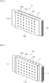
- FIG. 1 a perspective view illustrating a secondary battery according to various embodiments of the present invention is shown.
- FIG. 2 a cross-sectional view taken along line 2-2 of the secondary battery shown in FIG. 1 is shown.
- FIGS. 3A to 3C an exploded perspective view, a perspective view, and a cross-sectional view of a portion of an electrode assembly in the secondary battery shown in FIG. 1 are shown.
- the secondary battery 100 of the present invention will be described with reference to FIGS. 1, 2 , 3A and 3B .
- the secondary battery 100 includes an electrode assembly 110, a first terminal part 120, a second terminal part 130, a case 140, and a cap assembly 150.
- the cap assembly 150 may include a cap plate 151 sealing an upper opening 141 of the case 140.
- the electrode assembly 110 may be formed by winding a stack of a first electrode plate, a separator, and a second electrode plate, which are formed as thin plates or films, in the shape of a jelly roll.
- a coating layer 116 may be further formed on the outermost surface of the jelly-roll shaped electrode assembly 110.
- the first electrode plate 111 may operate as a negative electrode and the second electrode plate 112 may operate as a positive electrode, and on the contrary, the first electrode plate 111 may operate as a positive electrode and the second electrode plate 112 may operate as a negative electrode.
- the first electrode plate 111 operates as a negative electrode and the second electrode plate 112 operates as a positive electrode as an example.
- the first electrode plate 111 is formed by coating a first electrode active material 111b, such as graphite or carbon, on a first electrode current collector 111a made of a metal foil, such as copper, a copper alloy, nickel, or a nickel alloy, and may include a first electrode tab 114 (or a first uncoated portion) that is a region to which the first electrode active material is not applied.
- the first electrode tab 114 serves as a passage for current flow between the first electrode plate 111 and a first current collector tab 121.
- the first electrode tab 114 may protrude and extend a predetermined length toward one side of the electrode assembly 110.
- the second electrode plate 112 is formed by coating a second electrode active material 112b, such as a transition metal oxide, on a second electrode current collector 112a made of a metal foil, such as aluminum or an aluminum alloy, and may include a second electrode tab 115 (or a second uncoated portion) that is a region to which the second electrode active material 112b is not applied.
- the second electrode tab 115 serves as a passage for current flow between the second electrode plate 112 and a second current collector tab 131.
- the second electrode tab 115 may protrude and extend a predetermined length to the other side of the electrode assembly 110. That is, in the electrode assembly 110, the first electrode tab 114 and the second electrode tab 115 may protrude and extend to both sides in the longitudinal direction y, respectively.
- the separator 113 may be interposed between the first electrode plate 111 and the second electrode plate 112 to prevent an electric short and to enable movement of lithium ions.
- the separator 113 may extend further in the winding direction (x) than the first electrode plate 111 and the second electrode plate 112, so that the separator 113 may be positioned at the outermost portion of the electrode assembly 110.
- the separator 113 may be additionally further wound on the outermost surface of the electrode assembly 110 at least once, compared to the first electrode plate 111 and the second electrode plate 112.
- the separator 113 may expose the first electrode tab 114 and the second electrode tab 115 to the outside.
- the separator 113 may be formed at the central region A in the longitudinal direction y of the electrode assembly 110. That is, in the electrode assembly 110, the first electrode tab 114, the separator 113, and the second electrode tab 115 may be sequentially positioned along the longitudinal direction y.
- the separator 113 may be formed of a porous film including at least one selected from the group consisting of polystyrene (PS), polyethylene (PE), polypropylene (PP), polyvinylidene fluoride (PVdF), polytetrafluoroethylene (PTFE), polyurethane (PU), polymethylpentene (PMP), polyethylene terephthalate (PET), polycarbonate (PC), polyester, polyvinyl alcohol (PVA), polyacrylonitrile (PAN), silicone acrylic rubber, ethylene-methyl acrylate copolymer, polymethylene oxide (PMO), polymethyl methacrylate (PMMA), polyethylene oxide (PEO), polyamide (PA), polyamideimide (PAI), polysulfone (PSF), polyethylsulfone (PES), polyphenylene sulfide (PPS), polyarylate (PAR), polyimide (PI), polyaramid (PA), cellulose, modified cellulose, melamine-based resin, and phenol-based resin
- a coating layer 116 made of a heat-resistant material may be further formed on the surface of the outermost separator 113. That is, the coating layer 116 may be coated to cover the outer surface of the separator 113.
- the first electrode tab 114 and the second electrode tab 115 may be exposed to the outside of the coating layer 116. That is, in the electrode assembly 110, the first electrode tab 114 and the second electrode tab 115 may protrude from the coating layer 116 to both sides in the longitudinal direction of the electrode assembly 110, respectively.
- the coating layer 116 may include a single substance or a mixture of two or more selected from the group consisting of polyimide, polybutylene terephthalate (PBT), polyamideimide (PAI), perfluoroalkoxy (PFA), polysulfone (PSF), polyarylsulfone (PAS), polytetrafluoroethylene (PTFE), fluorinated ethylene propylene (FEP), ethylene tetrafluoroethylene (ETFE), and polyethylene naphthalene (PEN), which are liquid polymer materials having strong heat resistance.
- the coating layer 116 may be formed by spray coating, but the present invention is not limited thereto.
- the coating layer 116 is made of a heat-resistant material, and thus can prevent abnormal heat generation of the battery cell 110 from being transmitted to the outside through the case 140. Of course, the coating layer 116 may also prevent external heat from being transferred to the inside of the battery cell 110 through the case 140. In addition, since the coating layer 116 is made of an insulating material, insulation between the electrode assembly 110 and the case 140 may be improved. Of course, since the coating layer 116 is made of an insulating material, a separate insulating tape may not be provided at the outermost portion of the electrode assembly 110.
- the coating layer 116 may expose the separator 113 of the upper surface 110x and the lower surface 110y of the electrode assembly 110 to the outside. That is, the coating layer 116 may be formed to cover only the long side of the electrode assembly 110. Of course, the coating layer 116 may be formed to cover the separator 113 on the long side of the electrode assembly 110. The coating layer 116 may be formed to cover only the central region A on the long side of the electrode assembly 110. Here, when the coating layer 116 is formed to cover only the central region A of the long side of the electrode assembly 110, an electrolyte solution may be more easily absorbed into the electrode assembly 110.
- the coating layer 116 may have a plurality of holes 116a to partially expose the separator 113 on the long side of the electrode assembly 110 to the outside.
- the holes 116a may be arranged in a dot array form or a matrix form.
- each of the holes 116a is shown to have a circular shape, the shape may be changed in various manners including a polygonal shape, etc.
- the coating layer 116 may also expose the separator 113 of each of the upper surface 110x and the lower surface 110y of the electrode assembly 110 to the outside.
- a plurality of holes 116a may be provided in the coating layer 116 in a form in which the coating layer 116 covers all of the central region A of the electrode assembly 110.
- the holes 116a may partially expose to the outside the separator 113 on the long side, the upper surface, and the lower surface of the electrode assembly 110.
- the holes 116a include a plurality of holes, they may be arranged in a dot array form or a matrix form.
- each of the holes 116a is illustrated in a circular shape, the shape may be changed in various manners, including a polygonal shape or the like.
- the electrolyte solution may be more easily absorbed into the electrode assembly 110.
- the first electrode tab 114 and the second electrode tab 115 may be electrically connected respectively to the first electrode connection part 121a of the first current collector plate 121 and the second electrode connection part 121a of the second current collector plate 131, which are fixed to the cap assembly 150, by welding.
- the electrode assembly 110 is accommodated in the case 140 together with an electrolyte.
- the electrolyte may include a lithium salt, such as LiPF6 or LiBF4 in an organic solvent, such as EC, PC, DEC, EMC, or DMC.
- the electrolyte may be in a liquid, solid or gel form.
- the first terminal part 120 is made of metal, and is electrically connected to the first electrode tab 114 of the first electrode plate 111.
- the first terminal part 120 includes the first current collector plate 121, a terminal pole 122, and a terminal plate 123.
- the terminal pole 122 is electrically/mechanically connected between the first current collector plate 121 and the terminal plate 123.
- the first current collector plate 121 includes a first electrode connection part 121a that is in contact with and welded to the first electrode tab 114 of the first electrode plate 112, and a first terminal connection part 121b that is bent and extended from an upper end of the first electrode connection part 121 and is electrically and mechanically connected to the terminal pole 122.
- the first terminal connection part 121b includes a terminal hole 121c penetrating between the upper and lower surfaces thereof, and the terminal pole 122 is inserted thereinto to be riveted or welded.
- the first current collector plate 121 is made of, for example, copper or a copper alloy. However, the first current collector plate 121 is not limited to these materials.
- the terminal pole 122 protrudes and extends upward a predetermined length through the cap plate 151 to be described later, and is electrically connected to the first current collector plate 121 under the cap plate 151.
- the terminal pole 122 protrudes and extends a predetermined length to the upper portion of the cap plate 151, and is inserted into the terminal hole 121a of the first current collector plate 121 from the lower portion of the cap plate 151 to then be riveted or welded.
- the terminal pole 122 is electrically insulated from the cap plate 151.
- the terminal plate 123 has a hole 123a penetrating between the upper surface and the lower surface, and the terminal pole 122 is coupled and welded to the hole 123a.
- the terminal plate 123 may be coupled to the terminal pole 122 at an upper portion of the cap plate 151.
- a laser beam may be provided to a boundary region between the terminal pole 122 and the terminal plate 123 exposed upward, and the boundary region may be melted and then cooled and welded.
- the second terminal part 130 is also made of metal, and is electrically connected to the second electrode tab 115 of the second electrode plate 111.
- the second terminal part 130 may include a second current collector plate 131 and a terminal region 132.
- the second current collector plate 131 includes a second electrode connection part 131a that is in contact with and welded to the second electrode tab 115 of the second electrode plate 112, and a second terminal connection part 131b that is bent and extended from the upper end of the second electrode connection part 131 and is electrically and mechanically connected to a protrusion 151a of the cap plate 151.
- the second terminal connection part 131b has a terminal hole 131c penetrating between the upper and lower surfaces thereof, and the protrusion 151a is fitted and welded thereto.
- the second current collector plate 131 may be made of, for example, aluminum or an aluminum alloy. However, the second current collector plate 131 is not limited to these materials.
- the terminal region 133 may protrude upward from the cap plate 151.
- the terminal region 133 may be formed by a forging process when the cap plate 151 is formed, or may be formed by welding a separate metal plate. When the terminal region 133 is formed of a separate metal plate, it may be electrically and mechanically coupled to the upper surface of the cap plate 151.
- the terminal region 133 may be formed of aluminum or an aluminum alloy, which is the same as the cap plate 151.
- the terminal region 132 is electrically connected to the cap plate 151, the cap plate 151 and the case 140 to be described below have the same polarity as the second terminal part 130 (e.g., a positive polarity).
- the second terminal part 130 may serve as a positive electrode terminal.
- the case 140 is made of aluminum, an aluminum alloy, or a conductive metal, such as nickel-plated steel, and has a substantially hexahedral shape in which an opening 141 into which the electrode assembly 110 can be inserted and seated is formed.
- FIG. 2 shows a state in which the case 140 and the cap assembly 150 are coupled to each other, and the opening 141 of the case 140 may correspond to a peripheral portion coupled to the cap assembly 150. Meanwhile, the inner surface of the case 140 may be insulated to be insulated from the electrode assembly 110, the first terminal 120, the second terminal 130, and the cap assembly 150.
- the cap assembly 150 is coupled to the case 140.
- the cap assembly 150 specifically includes a cap plate 151, an upper insulating member 152, a plug 153, a safety vent 154, and a lower insulating member 155.
- the cap plate 151 may seal the opening of the case 140, and may be formed of the same material as the case 140.
- the cap plate 151 may be coupled to the case 140 by laser welding.
- the cap plate 151 may have the same polarity as that of the second terminal part 130.
- the cap plate 151 and the welded case 140 may have the same polarity.
- the upper insulating member 152 is formed between the terminal plate 123 and the cap plate 151. In addition, the upper insulating member 152 is in close contact with the cap plate 151 and the terminal plate 123. The upper insulating member 152 insulates the cap plate 151 and the terminal plate 123 from each other.
- the plug 153 seals an electrolyte injection hole of the cap plate 151
- the safety vent 154 is installed in a vent hole of the cap plate 151
- a notch is formed so as to be opened at a set pressure.
- the lower insulating member 155 may be interposed between the first current collector plate 121 and the cap plate 151 and between the cap plate 151 and the terminal pole 122.
- the lower insulating member 155 may prevent external moisture from penetrating the inside of the secondary battery 100 or prevent the electrolyte contained in the secondary battery 100 from leaking to the outside. Furthermore, the lower insulating member 155 may also be in close contact with the upper insulating member 152.
- the lower insulating member 155 insulates the first current collector plate 121 and the cap plate 151 from each other, and the terminal pole 122 and the cap plate 151 from each other.
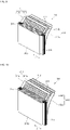
- FIG. 8 a perspective view illustrating a secondary battery according to another embodiment of the present invention before being accommodated in a case is shown.
- the perspective view and the cross-sectional view of the secondary battery 200 may be the same as those of the secondary battery 100 shown in FIGS. 1 and 2 .
- a first electrode tab 114 and a second electrode tab 115 may be welded respectively to a first electrode connection part 121a of a first current collector plate 121 and a second electrode connection part 131a of a second current collector plate 131, which are fixed to the cap assembly 150, and a coating layer 216 may then be formed.
- the coating layer 216 may be coated to cover not only the electrode assembly 110 but also the first and second current collectors 121 and 131.
- the electrode assembly 110 may have a short side surface on which the first electrode tab 114 and the second electrode tab 115 are positioned to be exposed to the outside.
- the coating layer 216 may be formed to cover the fixing tape 117 as well.
- the coating layer 216 may be formed to cover not only a central region A, in which the separator 113 is located on the long side of the electrode assembly 110, but also the first current collector plate 121 and the second current collector plate 131, which are coupled to the first electrode tab 114 and the second electrode tab 115. That is, the coating layer 216 may be formed to cover both of the long side surfaces of the electrode assembly 110. In addition, the coating layer 216 may be formed to cover both of the upper and lower surfaces of the electrode assembly 110.
- the coating layer 216 may have a hole formed to expose a part of the separator 113 of the electrode assembly 110 to the outside.
- FIG. 9 another example of a perspective view of an electrode assembly in the secondary battery shown in FIG. 1 is shown.
- the electrode assembly 310 may be formed in a stack form in which a first electrode plate 311, a second electrode plate 312, and a separator 313 between the first and second electrode plates 311 and 112 are sequentially stacked. That is, the electrode assembly 310 is not wound in the form of a jelly roll but is formed in the shape of a rectangular parallelepiped in which a square first electrode plate 311, a square separator 313, and a square second electrode plate 312, are sequentially stacked.
- the first electrode plate 311 may operate as a negative electrode and the second electrode plate 312 may operate as a positive electrode, and on the contrary, the first electrode plate 311 may operate as a positive electrode and the second electrode plate 312 may operate as a negative electrode.
- the first electrode plate 311 operates as a negative electrode and the second electrode plate 312 operates as a positive electrode as an example.
- the first electrode plate 311 is formed by coating a first electrode active material 311b, such as graphite or carbon, on a first electrode current collector 311a made of a metal foil, such as copper, a copper alloy, nickel, or a nickel alloy, and may include a first electrode tab 314 (or a first uncoated portion) that is a region to which the first electrode active material is not applied.
- the first electrode tab 314 serves as a passage for current flow between the first electrode plate 311 and a first current collector tab 121.
- the first electrode tab 314 may protrude and extend a predetermined length toward one side of the electrode assembly 310.
- the second electrode plate 312 is formed by coating a second electrode active material 312b, such as a transition metal oxide, on a second electrode current collector 312a made of a metal foil, such as aluminum or an aluminum alloy, and may include a second electrode tab 315 (or a second uncoated portion) that is a region to which the second electrode active material 312b is not applied.
- the second electrode tab 315 serves as a passage for current flow between the second electrode plate 312 and a second current collector tab 331.
- the second electrode tab 315 may protrude and extend a predetermined length to the other side of the electrode assembly 310. That is, in the electrode assembly 310, the first electrode tab 314 and the second electrode tab 315 may protrude and extend to both sides in the longitudinal direction y, respectively.
- the separator 313 may be interposed between the first electrode plate 311 and the second electrode plate 312 to prevent an electric short and to enable movement of lithium ions.
- the electrode assembly 310 may have a separator 313 positioned at the outermost portion. That is, the separator 313 may be positioned on the long side 310z of the electrode assembly 310.
- the separator 313 may be formed at the central region A in the longitudinal direction y of the electrode assembly 310. That is, in the electrode assembly 310, the first electrode tab 314, the separator 313, and the second electrode tab 315 may be sequentially positioned along the longitudinal direction y when viewed from the long side.
- the material of the separator 313 may be the same as that of the electrode assembly 110 shown in FIGS. 3A to 3C .
- a coating layer 116 may be further formed on the outermost separator 313.
- the shape of the coating layer 116 may be any one of the coating layers 116 shown in FIGS. 3B , 4 , 5 and 6 .
- the coating layer 116 may be coated on the inner surface of the outermost separator 313.
- the coating layer 116 may be coated on the inner surface of the outermost separator 313, and the electrode assembly 310 may then be coupled thereto.
- the outermost separator 313 may be a separator positioned at the outermost portion of the electrode assembly 310.
- the inner surface of the outermost separator 313 may be a surface facing the first electrode plate 311 or the second electrode plate 312, not the outer surface exposed to the outside of the outermost separator 313.
- a hole which is the same as that formed in the coating layer 116 shown in FIG. 5 , may be formed in the coating layer 116 coated on the inner surface of the outermost separator 313.
- the present invention can be applied to the field of a secondary battery and a battery pack composed of secondary batteries.
Abstract
The present invention relates to a secondary battery wherein a coating layer is formed by coating the surface of the outermost separator of an electrode assembly with a heat-resistant material, thereby preventing heat generated by abnormal heating of a battery cell from being transferred to the outside through a case or preventing external heat from being transferred to the inside of the battery cell. For example, the present invention provides a secondary battery comprising: an electrode assembly comprising a first electrode plate, a second electrode plate, and a separator interposed between the first electrode plate and the second electrode plate, wherein a first electrode tab that is a non-coated portion of the first electrode plate protrudes in one direction; a case in which the electrode assembly is received; a cap plate for sealing the upper end portion of the case; and a first terminal part electrically connected to the first electrode plate of the electrode assembly, the first terminal part being exposed to the outside of the cap plate. The separator is positioned at the outermost part of the electrode assembly, and a coating layer is formed by coating the surface of the outermost separator with a heat-resistant material.
Description
- Various embodiments of the present invention relate to a secondary battery.
- A secondary battery is a power storage system that provides excellent energy density for storing electrical energy in the form of chemical energy. Compared to non-rechargeable primary batteries, secondary batteries are rechargeable and are widely used in IT devices such as smartphones, cellular phones, laptops, and tablet PCs. Recently, in order to prevent environmental pollution, interest in electric vehicles has increased, and high-capacity secondary batteries are being adopted for electric vehicles accordingly. Such secondary batteries are required to have characteristics such as high density, high output, and stability.
- The above information disclosed in this Background section is only for enhancement of understanding of the background of the invention and therefore it may contain information that does not constitute prior art.
- The present invention provides a secondary battery wherein a coating layer is formed by coating the surface of the outermost separator of an electrode assembly with a heat-resistant material, thereby preventing heat generated by abnormal heating of a battery cell from being transferred to the outside through a case or preventing external heat from being transferred to the inside of the battery cell.
- A secondary battery according to an embodiment of the present invention comprises: an electrode assembly comprising a first electrode plate, a second electrode plate, and a separator interposed between the first electrode plate and the second electrode plate, wherein a first electrode tab that is a non-coated portion of the first electrode plate protrudes in one direction; a case in which the electrode assembly is received; a cap plate for sealing the upper end portion of the case; and a first terminal part electrically connected to the first electrode plate of the electrode assembly, the first terminal part being exposed to the outside of the cap plate, the separator is positioned at the outermost part of the electrode assembly, and a coating layer is formed by coating the surface of the outermost separator with a heat-resistant material.
- The electrode assembly may be formed by winding a stack of the first electrode plate, the separator, and the second electrode plate in the shape of a jelly roll, and the second electrode tab that is a non-coated portion of the second electrode plate may protrude in the other direction opposite to the first electrode tab.
- The electrode assembly may be formed in a stack form in which the first electrode plate, the separator, the second electrode plate, and the separator are sequentially stacked, and the second electrode tab that is a non-coated portion of the second electrode plate may protrude in the other direction opposite to the first electrode tab.
- The coating layer may be coated to cover all the outer surfaces of the separator, and the first electrode tab and the second electrode tab may protrude from the coating layer to both sides in the longitudinal direction of the electrode assembly, respectively.
- The coating layer may be formed such that a plurality of holes are disposed in a dot array or matrix form, and the separator may be exposed to the outside through the plurality of holes.
- The coating layer may be coated to cover the separator positioned on the long side of the electrode assembly, and the separator may be exposed to the outside through the upper and lower surfaces of the electrode assembly.
- The coating layer may be formed such that a plurality of holes are arranged in a dot array or matrix form, and the separator may be exposed to the outside through the plurality of holes.
- The coating layer may be coated on the inner surface of the outermost separator.
- The first electrode tab may be connected to a first current collector plate accommodated inside the case at the first terminal part, and the second electrode tab may be connected to a second current collector plate accommodated inside the case at the second terminal part exposed to the outside of the cap plate.
- The coating layer may be coated to cover a fixing tape for fixing the outermost separator to the outermost surface of the electrode assembly and the first and second current collector plates.
- The separator may be a porous film including at least one selected from the group consisting of polystyrene (PS), polyethylene (PE), polypropylene (PP), polyvinylidene fluoride (PVdF), polytetrafluoroethylene (PTFE), polyurethane (PU), polymethylpentene (PMP), polyethylene terephthalate (PET), polycarbonate (PC), polyester, polyvinyl alcohol (PVA), polyacrylonitrile (PAN), silicone acrylic rubber, ethylene-methyl acrylate copolymer, polymethylene oxide (PMO), polymethyl methacrylate (PMMA), polyethylene oxide (PEO), polyamide (PA), polyamideimide (PAI), polysulfone (PSF), polyethylsulfone (PES), polyphenylene sulfide (PPS), polyarylate (PAR), polyimide (PI), polyaramid (PA), cellulose (cellulose), modified cellulose, a melamine-based resin, and a phenol-based resin.
- The coating layer is a single substance or a mixture of two or more selected from the group consisting of polyimide, polybutylene terephthalate (PBT), polyamideimide (PAI), perfluoroalkoxy (PFA), polysulfone (PSF), polyarylsulfone (PAS), polytetrafluoroethylene (PTFE), fluorinated ethylene propylene (FEP), ethylene tetrafluoroethylene (ETFE), and polyethylene naphthalene (PEN), which are liquid polymer materials having strong heat resistance.
- In the secondary battery according to an embodiment of the present invention, a coating layer of a heat-resistant material is coated on the surface of the outermost separator of an electrode assembly with a heat-resistant material, thereby preventing heat generated by abnormal heating of a battery cell from being transferred to the outside through a case or preventing external heat from being transferred to the inside of the battery cell.
-
-
FIG. 1 is a perspective view illustrating a secondary battery according to various embodiments of the present invention. -
FIG. 2 is a cross-sectional view taken along line 2-2 of the secondary battery shown inFIG. 1 . -
FIGS. 3A to 3C are examples of an exploded perspective view, a perspective view, and a cross-sectional view of a portion of an electrode assembly in the secondary battery shown inFIG. 1 . -
FIG. 4 is a perspective view illustrating another example of a coating layer in the electrode assembly shown inFIG. 3B . -
FIG. 5 is a perspective view illustrating another example of a coating layer in the electrode assembly shown inFIG. 3B . -
FIG. 6 is a perspective view illustrating another example of a coating layer in the electrode assembly shown inFIG. 3B . -
FIG. 7 is a perspective view illustrating the configuration of the secondary battery shown inFIG. 1 before being accommodated in a case. -
FIG. 8 is a perspective view illustrating a secondary battery according to another embodiment of the present invention before being accommodated in a case. -
FIG. 9 shows another example of a perspective view of an electrode assembly in the secondary battery shown inFIG. 1 . - Hereinafter, preferred embodiments of the present invention will be described in detail with reference to the accompanying drawings.
- Examples of the present invention are provided to more completely explain the present invention to those skilled in the art, and the following examples may be modified in various other forms. The present invention, however, may be embodied in many different forms and should not be construed as being limited to the example (or exemplary) embodiments set forth herein. Rather, these example embodiments are provided so that this disclosure will be thorough and complete and will convey the aspects and features of the present invention to those skilled in the art.
- In addition, in the accompanying drawings, sizes or thicknesses of various components are exaggerated for brevity and clarity. Like numbers refer to like elements throughout. As used herein, the term "and/or" includes any and all combinations of one or more of the associated listed items. In addition, it will be understood that when an element A is referred to as being "connected to" an element B, the element A can be directly connected to the element B or an intervening element C may be present therebetween such that the element A and the element B are indirectly connected to each other.
- The terminology used herein is for the purpose of describing particular embodiments only and is not intended to be limiting of the disclosure. As used herein, the singular forms are intended to include the plural forms as well, unless the context clearly indicates otherwise. It will be further understood that the terms that the terms "comprise" and/or "comprising," when used in this specification, specify the presence of stated features, numbers, steps, operations, elements, and/or components, but do not preclude the presence or addition of one or more other features, numbers, steps, operations, elements, components, and/or groups thereof.
- It will be understood that, although the terms first, second, etc. may be used herein to describe various members, elements, regions, layers and/or sections, these members, elements, regions, layers and/or sections should not be limited by these terms. These terms are only used to distinguish one member, element, region, layer and/or section from another. Thus, for example, a first member, a first element, a first region, a first layer and/or a first section discussed below could be termed a second member, a second element, a second region, a second layer and/or a second section without departing from the teachings of the present invention.
- Spatially relative terms, such as "beneath," "below," "lower," "above," "upper," and the like, may be used herein for ease of description to describe one element or feature's relationship to another element(s) or feature(s) as illustrated in the figures. It will be understood that the spatially relative terms are intended to encompass different orientations of the device in use or operation in addition to the orientation depicted in the figures. For example, if the element or feature in the figures is turned over, elements described as "below" or "beneath" other elements or features would then be oriented "on" or "above" the other elements or features. Thus, the exemplary term "below" can encompass both an orientation of above and below.
- Referring to
FIG. 1 , a perspective view illustrating a secondary battery according to various embodiments of the present invention is shown. Referring toFIG. 2 , a cross-sectional view taken along line 2-2 of the secondary battery shown inFIG. 1 is shown. In addition, referring toFIGS. 3A to 3C , an exploded perspective view, a perspective view, and a cross-sectional view of a portion of an electrode assembly in the secondary battery shown inFIG. 1 are shown. Hereinafter, thesecondary battery 100 of the present invention will be described with reference toFIGS. 1, 2 ,3A and 3B . - As shown in
FIGS. 1, 2 ,3A and 3B , thesecondary battery 100 includes anelectrode assembly 110, a firstterminal part 120, a secondterminal part 130, acase 140, and acap assembly 150. Here, thecap assembly 150 may include acap plate 151 sealing anupper opening 141 of thecase 140. - First, the
electrode assembly 110 may be formed by winding a stack of a first electrode plate, a separator, and a second electrode plate, which are formed as thin plates or films, in the shape of a jelly roll. In addition, acoating layer 116 may be further formed on the outermost surface of the jelly-roll shapedelectrode assembly 110. - Here, the
first electrode plate 111 may operate as a negative electrode and thesecond electrode plate 112 may operate as a positive electrode, and on the contrary, thefirst electrode plate 111 may operate as a positive electrode and thesecond electrode plate 112 may operate as a negative electrode. However, in the present invention, for convenience of explanation, explanations will be given assuming that thefirst electrode plate 111 operates as a negative electrode and thesecond electrode plate 112 operates as a positive electrode as an example. - The
first electrode plate 111 is formed by coating a first electrodeactive material 111b, such as graphite or carbon, on a first electrodecurrent collector 111a made of a metal foil, such as copper, a copper alloy, nickel, or a nickel alloy, and may include a first electrode tab 114 (or a first uncoated portion) that is a region to which the first electrode active material is not applied. Thefirst electrode tab 114 serves as a passage for current flow between thefirst electrode plate 111 and a firstcurrent collector tab 121. Here, as shown inFIGS. 3A and 3B , thefirst electrode tab 114 may protrude and extend a predetermined length toward one side of theelectrode assembly 110. - The
second electrode plate 112 is formed by coating a second electrodeactive material 112b, such as a transition metal oxide, on a second electrodecurrent collector 112a made of a metal foil, such as aluminum or an aluminum alloy, and may include a second electrode tab 115 (or a second uncoated portion) that is a region to which the second electrodeactive material 112b is not applied. Thesecond electrode tab 115 serves as a passage for current flow between thesecond electrode plate 112 and a secondcurrent collector tab 131. Here, as shown inFIGS. 3A and 3B , thesecond electrode tab 115 may protrude and extend a predetermined length to the other side of theelectrode assembly 110. That is, in theelectrode assembly 110, thefirst electrode tab 114 and thesecond electrode tab 115 may protrude and extend to both sides in the longitudinal direction y, respectively. - The
separator 113 may be interposed between thefirst electrode plate 111 and thesecond electrode plate 112 to prevent an electric short and to enable movement of lithium ions. Theseparator 113 may extend further in the winding direction (x) than thefirst electrode plate 111 and thesecond electrode plate 112, so that theseparator 113 may be positioned at the outermost portion of theelectrode assembly 110. For example, theseparator 113 may be additionally further wound on the outermost surface of theelectrode assembly 110 at least once, compared to thefirst electrode plate 111 and thesecond electrode plate 112. Of course, theseparator 113 may expose thefirst electrode tab 114 and thesecond electrode tab 115 to the outside. Theseparator 113 may be formed at the central region A in the longitudinal direction y of theelectrode assembly 110. That is, in theelectrode assembly 110, thefirst electrode tab 114, theseparator 113, and thesecond electrode tab 115 may be sequentially positioned along the longitudinal direction y. - The
separator 113 may be formed of a porous film including at least one selected from the group consisting of polystyrene (PS), polyethylene (PE), polypropylene (PP), polyvinylidene fluoride (PVdF), polytetrafluoroethylene (PTFE), polyurethane (PU), polymethylpentene (PMP), polyethylene terephthalate (PET), polycarbonate (PC), polyester, polyvinyl alcohol (PVA), polyacrylonitrile (PAN), silicone acrylic rubber, ethylene-methyl acrylate copolymer, polymethylene oxide (PMO), polymethyl methacrylate (PMMA), polyethylene oxide (PEO), polyamide (PA), polyamideimide (PAI), polysulfone (PSF), polyethylsulfone (PES), polyphenylene sulfide (PPS), polyarylate (PAR), polyimide (PI), polyaramid (PA), cellulose, modified cellulose, melamine-based resin, and phenol-based resin. - In addition, after the winding of the
electrode assembly 110 is completed, acoating layer 116 made of a heat-resistant material may be further formed on the surface of theoutermost separator 113. That is, thecoating layer 116 may be coated to cover the outer surface of theseparator 113. Of course, in this case, thefirst electrode tab 114 and thesecond electrode tab 115 may be exposed to the outside of thecoating layer 116. That is, in theelectrode assembly 110, thefirst electrode tab 114 and thesecond electrode tab 115 may protrude from thecoating layer 116 to both sides in the longitudinal direction of theelectrode assembly 110, respectively. - Here, the
coating layer 116 may include a single substance or a mixture of two or more selected from the group consisting of polyimide, polybutylene terephthalate (PBT), polyamideimide (PAI), perfluoroalkoxy (PFA), polysulfone (PSF), polyarylsulfone (PAS), polytetrafluoroethylene (PTFE), fluorinated ethylene propylene (FEP), ethylene tetrafluoroethylene (ETFE), and polyethylene naphthalene (PEN), which are liquid polymer materials having strong heat resistance. Thecoating layer 116 may be formed by spray coating, but the present invention is not limited thereto. - The
coating layer 116 is made of a heat-resistant material, and thus can prevent abnormal heat generation of thebattery cell 110 from being transmitted to the outside through thecase 140. Of course, thecoating layer 116 may also prevent external heat from being transferred to the inside of thebattery cell 110 through thecase 140. In addition, since thecoating layer 116 is made of an insulating material, insulation between theelectrode assembly 110 and thecase 140 may be improved. Of course, since thecoating layer 116 is made of an insulating material, a separate insulating tape may not be provided at the outermost portion of theelectrode assembly 110. - As another example, as shown in
FIG. 4 , thecoating layer 116 may expose theseparator 113 of theupper surface 110x and thelower surface 110y of theelectrode assembly 110 to the outside. That is, thecoating layer 116 may be formed to cover only the long side of theelectrode assembly 110. Of course, thecoating layer 116 may be formed to cover theseparator 113 on the long side of theelectrode assembly 110. Thecoating layer 116 may be formed to cover only the central region A on the long side of theelectrode assembly 110. Here, when thecoating layer 116 is formed to cover only the central region A of the long side of theelectrode assembly 110, an electrolyte solution may be more easily absorbed into theelectrode assembly 110. - Additionally, as shown in
FIG. 5 , thecoating layer 116 may have a plurality ofholes 116a to partially expose theseparator 113 on the long side of theelectrode assembly 110 to the outside. Here, theholes 116a may be arranged in a dot array form or a matrix form. Also, although each of theholes 116a is shown to have a circular shape, the shape may be changed in various manners including a polygonal shape, etc. Additionally, thecoating layer 116 may also expose theseparator 113 of each of theupper surface 110x and thelower surface 110y of theelectrode assembly 110 to the outside. - Additionally, as shown in
FIG. 6 , a plurality ofholes 116a may be provided in thecoating layer 116 in a form in which thecoating layer 116 covers all of the central region A of theelectrode assembly 110. In this case, theholes 116a may partially expose to the outside theseparator 113 on the long side, the upper surface, and the lower surface of theelectrode assembly 110. Here, when theholes 116a include a plurality of holes, they may be arranged in a dot array form or a matrix form. Of course, although each of theholes 116a is illustrated in a circular shape, the shape may be changed in various manners, including a polygonal shape or the like. - As described above, by additionally forming the
holes 116a in thecoating layer 116, the electrolyte solution may be more easily absorbed into theelectrode assembly 110. - As shown in
FIG. 7 , in theelectrode assembly 110, after theoutermost separator 113 is fixed by means of a fixingtape 117, thefirst electrode tab 114 and thesecond electrode tab 115 may be electrically connected respectively to the firstelectrode connection part 121a of the firstcurrent collector plate 121 and the secondelectrode connection part 121a of the secondcurrent collector plate 131, which are fixed to thecap assembly 150, by welding. - The
electrode assembly 110 is accommodated in thecase 140 together with an electrolyte. The electrolyte may include a lithium salt, such as LiPF6 or LiBF4 in an organic solvent, such as EC, PC, DEC, EMC, or DMC. In addition, the electrolyte may be in a liquid, solid or gel form. - The first
terminal part 120 is made of metal, and is electrically connected to thefirst electrode tab 114 of thefirst electrode plate 111. The firstterminal part 120 includes the firstcurrent collector plate 121, aterminal pole 122, and aterminal plate 123. Here, theterminal pole 122 is electrically/mechanically connected between the firstcurrent collector plate 121 and theterminal plate 123. - The first
current collector plate 121 includes a firstelectrode connection part 121a that is in contact with and welded to thefirst electrode tab 114 of thefirst electrode plate 112, and a firstterminal connection part 121b that is bent and extended from an upper end of the firstelectrode connection part 121 and is electrically and mechanically connected to theterminal pole 122. The firstterminal connection part 121b includes aterminal hole 121c penetrating between the upper and lower surfaces thereof, and theterminal pole 122 is inserted thereinto to be riveted or welded. The firstcurrent collector plate 121 is made of, for example, copper or a copper alloy. However, the firstcurrent collector plate 121 is not limited to these materials. - The
terminal pole 122 protrudes and extends upward a predetermined length through thecap plate 151 to be described later, and is electrically connected to the firstcurrent collector plate 121 under thecap plate 151. In addition, theterminal pole 122 protrudes and extends a predetermined length to the upper portion of thecap plate 151, and is inserted into theterminal hole 121a of the firstcurrent collector plate 121 from the lower portion of thecap plate 151 to then be riveted or welded. Here, theterminal pole 122 is electrically insulated from thecap plate 151. - The
terminal plate 123 has ahole 123a penetrating between the upper surface and the lower surface, and theterminal pole 122 is coupled and welded to thehole 123a. Theterminal plate 123 may be coupled to theterminal pole 122 at an upper portion of thecap plate 151. For example, a laser beam may be provided to a boundary region between theterminal pole 122 and theterminal plate 123 exposed upward, and the boundary region may be melted and then cooled and welded. - The second
terminal part 130 is also made of metal, and is electrically connected to thesecond electrode tab 115 of thesecond electrode plate 111. The secondterminal part 130 may include a secondcurrent collector plate 131 and a terminal region 132. The secondcurrent collector plate 131 includes a secondelectrode connection part 131a that is in contact with and welded to thesecond electrode tab 115 of thesecond electrode plate 112, and a secondterminal connection part 131b that is bent and extended from the upper end of the secondelectrode connection part 131 and is electrically and mechanically connected to aprotrusion 151a of thecap plate 151. The secondterminal connection part 131b has a terminal hole 131c penetrating between the upper and lower surfaces thereof, and theprotrusion 151a is fitted and welded thereto. The secondcurrent collector plate 131 may be made of, for example, aluminum or an aluminum alloy. However, the secondcurrent collector plate 131 is not limited to these materials. - The
terminal region 133 may protrude upward from thecap plate 151. Theterminal region 133 may be formed by a forging process when thecap plate 151 is formed, or may be formed by welding a separate metal plate. When theterminal region 133 is formed of a separate metal plate, it may be electrically and mechanically coupled to the upper surface of thecap plate 151. - In addition, the
terminal region 133 may be formed of aluminum or an aluminum alloy, which is the same as thecap plate 151. Here, the terminal region 132 is electrically connected to thecap plate 151, thecap plate 151 and thecase 140 to be described below have the same polarity as the second terminal part 130 (e.g., a positive polarity). Of course, accordingly, the secondterminal part 130 may serve as a positive electrode terminal. - The
case 140 is made of aluminum, an aluminum alloy, or a conductive metal, such as nickel-plated steel, and has a substantially hexahedral shape in which anopening 141 into which theelectrode assembly 110 can be inserted and seated is formed.FIG. 2 shows a state in which thecase 140 and thecap assembly 150 are coupled to each other, and theopening 141 of thecase 140 may correspond to a peripheral portion coupled to thecap assembly 150. Meanwhile, the inner surface of thecase 140 may be insulated to be insulated from theelectrode assembly 110, thefirst terminal 120, thesecond terminal 130, and thecap assembly 150. - The
cap assembly 150 is coupled to thecase 140. Thecap assembly 150 specifically includes acap plate 151, an upper insulatingmember 152, aplug 153, asafety vent 154, and a lower insulatingmember 155. - The
cap plate 151 may seal the opening of thecase 140, and may be formed of the same material as thecase 140. For example, thecap plate 151 may be coupled to thecase 140 by laser welding. Here, thecap plate 151 may have the same polarity as that of the secondterminal part 130. Also, thecap plate 151 and the weldedcase 140 may have the same polarity. - The upper insulating
member 152 is formed between theterminal plate 123 and thecap plate 151. In addition, the upper insulatingmember 152 is in close contact with thecap plate 151 and theterminal plate 123. The upper insulatingmember 152 insulates thecap plate 151 and theterminal plate 123 from each other. - The
plug 153 seals an electrolyte injection hole of thecap plate 151, thesafety vent 154 is installed in a vent hole of thecap plate 151, and a notch is formed so as to be opened at a set pressure. - The lower insulating
member 155 may be interposed between the firstcurrent collector plate 121 and thecap plate 151 and between thecap plate 151 and theterminal pole 122. The lower insulatingmember 155 may prevent external moisture from penetrating the inside of thesecondary battery 100 or prevent the electrolyte contained in thesecondary battery 100 from leaking to the outside. Furthermore, the lower insulatingmember 155 may also be in close contact with the upper insulatingmember 152. - In addition, the lower insulating
member 155 insulates the firstcurrent collector plate 121 and thecap plate 151 from each other, and theterminal pole 122 and thecap plate 151 from each other. - Referring to
FIG. 8 , a perspective view illustrating a secondary battery according to another embodiment of the present invention before being accommodated in a case is shown. The perspective view and the cross-sectional view of thesecondary battery 200 may be the same as those of thesecondary battery 100 shown inFIGS. 1 and 2 . However, in thesecondary battery 200, after theoutermost separator 113 is fixed by means of a fixingtape 117, afirst electrode tab 114 and asecond electrode tab 115 may be welded respectively to a firstelectrode connection part 121a of a firstcurrent collector plate 121 and a secondelectrode connection part 131a of a secondcurrent collector plate 131, which are fixed to thecap assembly 150, and acoating layer 216 may then be formed. That is, thecoating layer 216 may be coated to cover not only theelectrode assembly 110 but also the first and secondcurrent collectors electrode assembly 110 may have a short side surface on which thefirst electrode tab 114 and thesecond electrode tab 115 are positioned to be exposed to the outside. Of course, thecoating layer 216 may be formed to cover the fixingtape 117 as well. - The
coating layer 216 may be formed to cover not only a central region A, in which theseparator 113 is located on the long side of theelectrode assembly 110, but also the firstcurrent collector plate 121 and the secondcurrent collector plate 131, which are coupled to thefirst electrode tab 114 and thesecond electrode tab 115. That is, thecoating layer 216 may be formed to cover both of the long side surfaces of theelectrode assembly 110. In addition, thecoating layer 216 may be formed to cover both of the upper and lower surfaces of theelectrode assembly 110. - In order to increase the absorption of an electrolyte by the
electrode assembly 110, as shown inFIGS. 5 and 6 , thecoating layer 216 may have a hole formed to expose a part of theseparator 113 of theelectrode assembly 110 to the outside. - Referring to
FIG. 9 , another example of a perspective view of an electrode assembly in the secondary battery shown inFIG. 1 is shown. - The
electrode assembly 310 may be formed in a stack form in which afirst electrode plate 311, asecond electrode plate 312, and aseparator 313 between the first andsecond electrode plates electrode assembly 310 is not wound in the form of a jelly roll but is formed in the shape of a rectangular parallelepiped in which a squarefirst electrode plate 311, asquare separator 313, and a squaresecond electrode plate 312, are sequentially stacked. - Here, the
first electrode plate 311 may operate as a negative electrode and thesecond electrode plate 312 may operate as a positive electrode, and on the contrary, thefirst electrode plate 311 may operate as a positive electrode and thesecond electrode plate 312 may operate as a negative electrode. However, in the present invention, for convenience of explanation, explanations will be given assuming that thefirst electrode plate 311 operates as a negative electrode and thesecond electrode plate 312 operates as a positive electrode as an example. - The
first electrode plate 311 is formed by coating a first electrodeactive material 311b, such as graphite or carbon, on a first electrodecurrent collector 311a made of a metal foil, such as copper, a copper alloy, nickel, or a nickel alloy, and may include a first electrode tab 314 (or a first uncoated portion) that is a region to which the first electrode active material is not applied. Thefirst electrode tab 314 serves as a passage for current flow between thefirst electrode plate 311 and a firstcurrent collector tab 121. Here, thefirst electrode tab 314 may protrude and extend a predetermined length toward one side of theelectrode assembly 310. - The
second electrode plate 312 is formed by coating a second electrodeactive material 312b, such as a transition metal oxide, on a second electrodecurrent collector 312a made of a metal foil, such as aluminum or an aluminum alloy, and may include a second electrode tab 315 (or a second uncoated portion) that is a region to which the second electrodeactive material 312b is not applied. Thesecond electrode tab 315 serves as a passage for current flow between thesecond electrode plate 312 and a second current collector tab 331. Here, thesecond electrode tab 315 may protrude and extend a predetermined length to the other side of theelectrode assembly 310. That is, in theelectrode assembly 310, thefirst electrode tab 314 and thesecond electrode tab 315 may protrude and extend to both sides in the longitudinal direction y, respectively. - The
separator 313 may be interposed between thefirst electrode plate 311 and thesecond electrode plate 312 to prevent an electric short and to enable movement of lithium ions. Theelectrode assembly 310 may have aseparator 313 positioned at the outermost portion. That is, theseparator 313 may be positioned on thelong side 310z of theelectrode assembly 310. - The
separator 313 may be formed at the central region A in the longitudinal direction y of theelectrode assembly 310. That is, in theelectrode assembly 310, thefirst electrode tab 314, theseparator 313, and thesecond electrode tab 315 may be sequentially positioned along the longitudinal direction y when viewed from the long side. The material of theseparator 313 may be the same as that of theelectrode assembly 110 shown inFIGS. 3A to 3C . - Of course, in the
electrode assembly 313, acoating layer 116 may be further formed on theoutermost separator 313. Here, the shape of thecoating layer 116 may be any one of the coating layers 116 shown inFIGS. 3B ,4 ,5 and 6 . - Additionally, as shown in
FIG. 10 , thecoating layer 116 may be coated on the inner surface of theoutermost separator 313. Of course, prior to coupling of theelectrode assembly 310, thecoating layer 116 may be coated on the inner surface of theoutermost separator 313, and theelectrode assembly 310 may then be coupled thereto. Here, theoutermost separator 313 may be a separator positioned at the outermost portion of theelectrode assembly 310. In addition, the inner surface of theoutermost separator 313 may be a surface facing thefirst electrode plate 311 or thesecond electrode plate 312, not the outer surface exposed to the outside of theoutermost separator 313. - Of course, a hole, which is the same as that formed in the
coating layer 116 shown inFIG. 5 , may be formed in thecoating layer 116 coated on the inner surface of theoutermost separator 313. - While the foregoing embodiment has been provided for carrying out the secondary battery according to the present invention, it should be understood that the embodiment described herein should be considered in a descriptive sense only and not for purposes of limitation, and various changes in form and details may be made therein without departing from the spirit and scope of the disclosure as defined by the following claims.
- The present invention can be applied to the field of a secondary battery and a battery pack composed of secondary batteries.
Claims (12)
- A secondary battery comprising:an electrode assembly comprising a first electrode plate, a second electrode plate, and a separator interposed between the first electrode plate and the second electrode plate, wherein a first electrode tab that is a non-coated portion of the first electrode plate protrudes in one direction;a case in which the electrode assembly is received;a cap plate for sealing the upper end portion of the case; anda first terminal part electrically connected to the first electrode plate of the electrode assembly, the first terminal part being exposed to the outside of the cap plate,wherein the separator is positioned at the outermost part of the electrode assembly, and a coating layer is formed by coating the surface of the outermost separator with a heat-resistant material.
- The secondary battery of claim 1, wherein the electrode assembly is formed by winding a stack of the first electrode plate, the separator, and the second electrode plate in the shape of a jelly roll, and the second electrode tab that is a non-coated portion of the second electrode plate protrudes in the other direction opposite to the first electrode tab.
- The secondary battery of claim 1, wherein the electrode assembly is formed in a stack form in which the first electrode plate, the separator, the second electrode plate, and the separator are sequentially stacked, and the second electrode tab that is a non-coated portion of the second electrode plate protrudes in the other direction opposite to the first electrode tab.
- The secondary battery of claim 2 or 3, wherein the coating layer is coated to cover all the outer surfaces of the separator, and the first electrode tab and the second electrode tab protrude from the coating layer to both sides in the longitudinal direction of the electrode assembly, respectively.
- The secondary battery of claim 4, wherein the coating layer is formed such that a plurality of holes are arranged in a dot array or matrix form, and the separator is exposed to the outside through the plurality of holes.
- The secondary battery of claim 2, wherein the coating layer is coated to cover the separator positioned on the long side of the electrode assembly, and the separator is exposed to the outside through upper and lower surfaces of the electrode assembly.
- The secondary battery of claim 6, wherein the coating layer is formed such that a plurality of holes are arranged in a dot array or matrix form, and the separator is exposed to the outside through the plurality of holes.
- The secondary battery of claim 3, wherein the coating layer is coated on the inner surface of the outermost separator.
- The secondary battery of claim 2, wherein the first electrode tab is connected to a first current collector plate accommodated inside the case at the first terminal part, and the second electrode tab is connected to a second current collector plate accommodated inside the case at the second terminal part exposed to the outside of the cap plate.
- The secondary battery of claim 9, wherein the coating layer is coated to cover a fixing tape for fixing the outermost separator to the outermost surface of the electrode assembly, and the first and second current collector plates.
- The secondary battery of claim 1, wherein the separator is a porous film including at least one selected from the group consisting of polystyrene (PS), polyethylene (PE), polypropylene (PP), polyvinylidene fluoride (PVdF), polytetrafluoroethylene (PTFE), polyurethane (PU), polymethylpentene (PMP), polyethylene terephthalate (PET), polycarbonate (PC), polyester, polyvinyl alcohol (PVA), polyacrylonitrile (PAN), silicone acrylic rubber, ethylene-methyl acrylate copolymer, polymethylene oxide (PMO), polymethyl methacrylate (PMMA), polyethylene oxide (PEO), polyamide (PA), polyamideimide (PAI), polysulfone (PSF), polyethylsulfone (PES), polyphenylene sulfide (PPS), polyarylate (PAR), polyimide (PI), polyaramid (PA), cellulose (cellulose), modified cellulose, a melamine-based resin, and a phenol-based resin.
- The secondary battery of claim 1, wherein the coating layer is a single substance or a mixture of two or more selected from the group consisting of polyimide, polybutylene terephthalate (PBT), polyamideimide (PAI), perfluoroalkoxy (PFA), polysulfone (PSF), polyarylsulfone (PAS), polytetrafluoroethylene (PTFE), fluorinated ethylene propylene (FEP), ethylene tetrafluoroethylene (ETFE), and polyethylene naphthalene (PEN), which are liquid polymer materials having strong heat resistance.
Applications Claiming Priority (2)
| Application Number | Priority Date | Filing Date | Title |
|---|---|---|---|
| KR1020200027733A KR20210112573A (en) | 2020-03-05 | 2020-03-05 | Secondary battery |
| PCT/KR2020/018313 WO2021177561A1 (en) | 2020-03-05 | 2020-12-15 | Secondary battery |
Publications (1)
| Publication Number | Publication Date |
|---|---|
| EP4117079A1 true EP4117079A1 (en) | 2023-01-11 |
Family
ID=77613667
Family Applications (1)
| Application Number | Title | Priority Date | Filing Date |
|---|---|---|---|
| EP20923032.5A Pending EP4117079A1 (en) | 2020-03-05 | 2020-12-15 | Secondary battery |
Country Status (5)
| Country | Link |
|---|---|
| US (1) | US20240145865A1 (en) |
| EP (1) | EP4117079A1 (en) |
| KR (1) | KR20210112573A (en) |
| CN (1) | CN114641886A (en) |
| WO (1) | WO2021177561A1 (en) |
Families Citing this family (1)
| Publication number | Priority date | Publication date | Assignee | Title |
|---|---|---|---|---|
| KR20230142245A (en) * | 2022-04-01 | 2023-10-11 | 삼성에스디아이 주식회사 | Sheet for rechargeable lithium battery and rechargeable lithium battery including the same |
Family Cites Families (7)
| Publication number | Priority date | Publication date | Assignee | Title |
|---|---|---|---|---|
| KR101154883B1 (en) * | 2007-04-26 | 2012-06-18 | 주식회사 엘지화학 | Method for Production of Electrode Assembly with Improved Electrolyte Wetting Property |
| KR101009517B1 (en) * | 2008-06-23 | 2011-01-18 | 삼성에스디아이 주식회사 | Electrode Assembly and Lithium Secondary battery with the Same |
| KR101147242B1 (en) * | 2010-04-01 | 2012-05-18 | 삼성에스디아이 주식회사 | Electrode assembly, and rechargeable battery using thereof |
| KR20140121205A (en) * | 2013-04-05 | 2014-10-15 | 삼성에스디아이 주식회사 | Secondary battery and method of insulating the outer surface of the same |
| KR20150057480A (en) * | 2013-11-19 | 2015-05-28 | 삼성에스디아이 주식회사 | Separator, lithium battery including the same, method for preparing the separator, and method for preparing the lithium battery |
| KR20150106808A (en) * | 2013-11-21 | 2015-09-22 | 삼성에스디아이 주식회사 | A secondary cell and a method for preparing the same |
| JP6270613B2 (en) * | 2014-04-25 | 2018-01-31 | 日立オートモティブシステムズ株式会社 | Prismatic secondary battery |
-
2020
- 2020-03-05 KR KR1020200027733A patent/KR20210112573A/en active Search and Examination
- 2020-12-15 CN CN202080076847.1A patent/CN114641886A/en active Pending
- 2020-12-15 WO PCT/KR2020/018313 patent/WO2021177561A1/en active Application Filing
- 2020-12-15 EP EP20923032.5A patent/EP4117079A1/en active Pending
- 2020-12-15 US US17/754,932 patent/US20240145865A1/en active Pending
Also Published As
| Publication number | Publication date |
|---|---|
| CN114641886A (en) | 2022-06-17 |
| KR20210112573A (en) | 2021-09-15 |
| WO2021177561A1 (en) | 2021-09-10 |
| US20240145865A1 (en) | 2024-05-02 |
Similar Documents
| Publication | Publication Date | Title |
|---|---|---|
| KR100973310B1 (en) | Electrode tab for secondary battery and secondary battery using the same | |
| US8771854B2 (en) | Secondary battery | |
| US9853294B2 (en) | Secondary battery and manufacturing method thereof | |
| US9088024B2 (en) | Secondary battery | |
| EP3799198A1 (en) | Secondary battery | |
| CN110326131B (en) | Secondary battery with symmetrical multiple tabs | |
| EP4303989A2 (en) | Battery case for secondary battery and manufacturing method of gas discharge part | |
| US8263245B2 (en) | Cap assembly and secondary battery using the same | |
| KR20200103474A (en) | The Apparatus For Venting | |
| EP4117079A1 (en) | Secondary battery | |
| US20230178833A1 (en) | Secondary battery | |
| EP3989306A1 (en) | Battery case for secondary battery and method for manufacturing pouch type secondary battery | |
| US11108095B2 (en) | Secondary battery | |
| US20240128609A1 (en) | Secondary battery | |
| US20230178861A1 (en) | Secondary battery | |
| US20240154256A1 (en) | Secondary battery and battery module including the same | |
| US20230231281A1 (en) | Secondary battery | |
| US20240106085A1 (en) | Secondary battery | |
| US20230231237A1 (en) | Secondary battery | |
| US8492014B2 (en) | Secondary battery | |
| US20230006313A1 (en) | Secondary battery | |
| US20230187789A1 (en) | Secondary battery | |
| US20240162538A1 (en) | Secondary battery | |
| KR20240063428A (en) | Secondary battery and battery module including the same | |
| KR20230071572A (en) | Battery Stack with Improved Cooling Ability And Battery Module Using The Same |
Legal Events
| Date | Code | Title | Description |
|---|---|---|---|
| STAA | Information on the status of an ep patent application or granted ep patent |
Free format text: STATUS: THE INTERNATIONAL PUBLICATION HAS BEEN MADE |
|
| PUAI | Public reference made under article 153(3) epc to a published international application that has entered the european phase |
Free format text: ORIGINAL CODE: 0009012 |
|
| STAA | Information on the status of an ep patent application or granted ep patent |
Free format text: STATUS: REQUEST FOR EXAMINATION WAS MADE |
|
| 17P | Request for examination filed |
Effective date: 20220311 |
|
| AK | Designated contracting states |
Kind code of ref document: A1 Designated state(s): AL AT BE BG CH CY CZ DE DK EE ES FI FR GB GR HR HU IE IS IT LI LT LU LV MC MK MT NL NO PL PT RO RS SE SI SK SM TR |
|
| DAV | Request for validation of the european patent (deleted) | ||
| DAX | Request for extension of the european patent (deleted) |