EP4117065A1 - Secondary battery - Google Patents
Secondary battery Download PDFInfo
- Publication number
- EP4117065A1 EP4117065A1 EP21764008.5A EP21764008A EP4117065A1 EP 4117065 A1 EP4117065 A1 EP 4117065A1 EP 21764008 A EP21764008 A EP 21764008A EP 4117065 A1 EP4117065 A1 EP 4117065A1
- Authority
- EP
- European Patent Office
- Prior art keywords
- wound
- positive electrode
- electrode
- tape
- electrode assembly
- Prior art date
- Legal status (The legal status is an assumption and is not a legal conclusion. Google has not performed a legal analysis and makes no representation as to the accuracy of the status listed.)
- Granted
Links
Images


Classifications
-
- H—ELECTRICITY
- H01—ELECTRIC ELEMENTS
- H01M—PROCESSES OR MEANS, e.g. BATTERIES, FOR THE DIRECT CONVERSION OF CHEMICAL ENERGY INTO ELECTRICAL ENERGY
- H01M10/00—Secondary cells; Manufacture thereof
- H01M10/04—Construction or manufacture in general
- H01M10/0431—Cells with wound or folded electrodes
-
- H—ELECTRICITY
- H01—ELECTRIC ELEMENTS
- H01M—PROCESSES OR MEANS, e.g. BATTERIES, FOR THE DIRECT CONVERSION OF CHEMICAL ENERGY INTO ELECTRICAL ENERGY
- H01M10/00—Secondary cells; Manufacture thereof
- H01M10/05—Accumulators with non-aqueous electrolyte
- H01M10/058—Construction or manufacture
- H01M10/0587—Construction or manufacture of accumulators having only wound construction elements, i.e. wound positive electrodes, wound negative electrodes and wound separators
-
- H—ELECTRICITY
- H01—ELECTRIC ELEMENTS
- H01M—PROCESSES OR MEANS, e.g. BATTERIES, FOR THE DIRECT CONVERSION OF CHEMICAL ENERGY INTO ELECTRICAL ENERGY
- H01M10/00—Secondary cells; Manufacture thereof
- H01M10/05—Accumulators with non-aqueous electrolyte
- H01M10/052—Li-accumulators
-
- H—ELECTRICITY
- H01—ELECTRIC ELEMENTS
- H01M—PROCESSES OR MEANS, e.g. BATTERIES, FOR THE DIRECT CONVERSION OF CHEMICAL ENERGY INTO ELECTRICAL ENERGY
- H01M10/00—Secondary cells; Manufacture thereof
- H01M10/42—Methods or arrangements for servicing or maintenance of secondary cells or secondary half-cells
- H01M10/4235—Safety or regulating additives or arrangements in electrodes, separators or electrolyte
-
- H—ELECTRICITY
- H01—ELECTRIC ELEMENTS
- H01M—PROCESSES OR MEANS, e.g. BATTERIES, FOR THE DIRECT CONVERSION OF CHEMICAL ENERGY INTO ELECTRICAL ENERGY
- H01M50/00—Constructional details or processes of manufacture of the non-active parts of electrochemical cells other than fuel cells, e.g. hybrid cells
- H01M50/40—Separators; Membranes; Diaphragms; Spacing elements inside cells
- H01M50/46—Separators, membranes or diaphragms characterised by their combination with electrodes
-
- H—ELECTRICITY
- H01—ELECTRIC ELEMENTS
- H01M—PROCESSES OR MEANS, e.g. BATTERIES, FOR THE DIRECT CONVERSION OF CHEMICAL ENERGY INTO ELECTRICAL ENERGY
- H01M50/00—Constructional details or processes of manufacture of the non-active parts of electrochemical cells other than fuel cells, e.g. hybrid cells
- H01M50/40—Separators; Membranes; Diaphragms; Spacing elements inside cells
- H01M50/471—Spacing elements inside cells other than separators, membranes or diaphragms; Manufacturing processes thereof
- H01M50/474—Spacing elements inside cells other than separators, membranes or diaphragms; Manufacturing processes thereof characterised by their position inside the cells
-
- H—ELECTRICITY
- H01—ELECTRIC ELEMENTS
- H01M—PROCESSES OR MEANS, e.g. BATTERIES, FOR THE DIRECT CONVERSION OF CHEMICAL ENERGY INTO ELECTRICAL ENERGY
- H01M50/00—Constructional details or processes of manufacture of the non-active parts of electrochemical cells other than fuel cells, e.g. hybrid cells
- H01M50/40—Separators; Membranes; Diaphragms; Spacing elements inside cells
- H01M50/471—Spacing elements inside cells other than separators, membranes or diaphragms; Manufacturing processes thereof
- H01M50/477—Spacing elements inside cells other than separators, membranes or diaphragms; Manufacturing processes thereof characterised by their shape
-
- H—ELECTRICITY
- H01—ELECTRIC ELEMENTS
- H01M—PROCESSES OR MEANS, e.g. BATTERIES, FOR THE DIRECT CONVERSION OF CHEMICAL ENERGY INTO ELECTRICAL ENERGY
- H01M50/00—Constructional details or processes of manufacture of the non-active parts of electrochemical cells other than fuel cells, e.g. hybrid cells
- H01M50/40—Separators; Membranes; Diaphragms; Spacing elements inside cells
- H01M50/471—Spacing elements inside cells other than separators, membranes or diaphragms; Manufacturing processes thereof
- H01M50/48—Spacing elements inside cells other than separators, membranes or diaphragms; Manufacturing processes thereof characterised by the material
-
- H—ELECTRICITY
- H01—ELECTRIC ELEMENTS
- H01M—PROCESSES OR MEANS, e.g. BATTERIES, FOR THE DIRECT CONVERSION OF CHEMICAL ENERGY INTO ELECTRICAL ENERGY
- H01M50/00—Constructional details or processes of manufacture of the non-active parts of electrochemical cells other than fuel cells, e.g. hybrid cells
- H01M50/50—Current conducting connections for cells or batteries
- H01M50/531—Electrode connections inside a battery casing
- H01M50/538—Connection of several leads or tabs of wound or folded electrode stacks
-
- H—ELECTRICITY
- H01—ELECTRIC ELEMENTS
- H01M—PROCESSES OR MEANS, e.g. BATTERIES, FOR THE DIRECT CONVERSION OF CHEMICAL ENERGY INTO ELECTRICAL ENERGY
- H01M50/00—Constructional details or processes of manufacture of the non-active parts of electrochemical cells other than fuel cells, e.g. hybrid cells
- H01M50/50—Current conducting connections for cells or batteries
- H01M50/543—Terminals
- H01M50/552—Terminals characterised by their shape
- H01M50/553—Terminals adapted for prismatic, pouch or rectangular cells
- H01M50/557—Plate-shaped terminals
-
- H—ELECTRICITY
- H01—ELECTRIC ELEMENTS
- H01M—PROCESSES OR MEANS, e.g. BATTERIES, FOR THE DIRECT CONVERSION OF CHEMICAL ENERGY INTO ELECTRICAL ENERGY
- H01M50/00—Constructional details or processes of manufacture of the non-active parts of electrochemical cells other than fuel cells, e.g. hybrid cells
- H01M50/50—Current conducting connections for cells or batteries
- H01M50/543—Terminals
- H01M50/564—Terminals characterised by their manufacturing process
- H01M50/566—Terminals characterised by their manufacturing process by welding, soldering or brazing
-
- H—ELECTRICITY
- H01—ELECTRIC ELEMENTS
- H01M—PROCESSES OR MEANS, e.g. BATTERIES, FOR THE DIRECT CONVERSION OF CHEMICAL ENERGY INTO ELECTRICAL ENERGY
- H01M50/00—Constructional details or processes of manufacture of the non-active parts of electrochemical cells other than fuel cells, e.g. hybrid cells
- H01M50/50—Current conducting connections for cells or batteries
- H01M50/572—Means for preventing undesired use or discharge
- H01M50/584—Means for preventing undesired use or discharge for preventing incorrect connections inside or outside the batteries
- H01M50/586—Means for preventing undesired use or discharge for preventing incorrect connections inside or outside the batteries inside the batteries, e.g. incorrect connections of electrodes
-
- H—ELECTRICITY
- H01—ELECTRIC ELEMENTS
- H01M—PROCESSES OR MEANS, e.g. BATTERIES, FOR THE DIRECT CONVERSION OF CHEMICAL ENERGY INTO ELECTRICAL ENERGY
- H01M50/00—Constructional details or processes of manufacture of the non-active parts of electrochemical cells other than fuel cells, e.g. hybrid cells
- H01M50/50—Current conducting connections for cells or batteries
- H01M50/572—Means for preventing undesired use or discharge
- H01M50/584—Means for preventing undesired use or discharge for preventing incorrect connections inside or outside the batteries
- H01M50/59—Means for preventing undesired use or discharge for preventing incorrect connections inside or outside the batteries characterised by the protection means
- H01M50/595—Tapes
-
- Y—GENERAL TAGGING OF NEW TECHNOLOGICAL DEVELOPMENTS; GENERAL TAGGING OF CROSS-SECTIONAL TECHNOLOGIES SPANNING OVER SEVERAL SECTIONS OF THE IPC; TECHNICAL SUBJECTS COVERED BY FORMER USPC CROSS-REFERENCE ART COLLECTIONS [XRACs] AND DIGESTS
- Y02—TECHNOLOGIES OR APPLICATIONS FOR MITIGATION OR ADAPTATION AGAINST CLIMATE CHANGE
- Y02E—REDUCTION OF GREENHOUSE GAS [GHG] EMISSIONS, RELATED TO ENERGY GENERATION, TRANSMISSION OR DISTRIBUTION
- Y02E60/00—Enabling technologies; Technologies with a potential or indirect contribution to GHG emissions mitigation
- Y02E60/10—Energy storage using batteries
-
- Y—GENERAL TAGGING OF NEW TECHNOLOGICAL DEVELOPMENTS; GENERAL TAGGING OF CROSS-SECTIONAL TECHNOLOGIES SPANNING OVER SEVERAL SECTIONS OF THE IPC; TECHNICAL SUBJECTS COVERED BY FORMER USPC CROSS-REFERENCE ART COLLECTIONS [XRACs] AND DIGESTS
- Y02—TECHNOLOGIES OR APPLICATIONS FOR MITIGATION OR ADAPTATION AGAINST CLIMATE CHANGE
- Y02P—CLIMATE CHANGE MITIGATION TECHNOLOGIES IN THE PRODUCTION OR PROCESSING OF GOODS
- Y02P70/00—Climate change mitigation technologies in the production process for final industrial or consumer products
- Y02P70/50—Manufacturing or production processes characterised by the final manufactured product
Definitions
- the present disclosure relates to a secondary battery.
- Secondary batteries such as an alkali secondary battery and a non-aqueous electrolyte secondary battery have been used in a driving power source for electric vehicle (EV) and hybrid electric vehicle (HEV, PHEV) or a stationary storage battery system for an application for suppressing an output variation of photovoltaic power generation, wind power generation, or the like, or for an application for a peak shift of grid power for storing power during the nighttime and utilizing the power in the daytime, for example.
- EV electric vehicle
- HEV hybrid electric vehicle
- PHEV hybrid electric vehicle
- stationary storage battery system for an application for suppressing an output variation of photovoltaic power generation, wind power generation, or the like, or for an application for a peak shift of grid power for storing power during the nighttime and utilizing the power in the daytime, for example.
- a foreign substance may be mixed while the secondary battery is assembled, for example.
- the mixed foreign substance is a conductive foreign substance such as a metal foreign substance
- an internal short circuit may occur.
- the metal foreign substance adheres to a positive electrode plate, for example, the metal foreign substance is dissolved as metal ions in an electrolytic solution due to a high potential of a positive electrode plate, and is deposited as a metal when the metal ions reach a negative electrode plate.
- the metal is deposited to grow toward the positive electrode plate, and the metal pierces a separator and contacts the positive electrode plate, an internal short circuit occurs.
- the mixed metal foreign substance may also directly pierce the separator so that an internal short circuit occurs.
- Patent Literature 1 proposes a secondary battery in which an insulating member covers a positive electrode exposure part or a negative electrode exposure part, and an end portion of a separator adjacent to the outer periphery of the positive electrode exposure part or the negative electrode exposure part, for the purpose of preventing an internal short circuit from occurring due to a mixed foreign substance.
- PATENT LITERATURE 1 Japanese Unexamined Patent Application Publication No. 2012-49073
- a secondary battery according to an aspect of the present disclosure comprises
- a configuration of the secondary battery according to the aspect of the present disclosure makes it possible to prevent a foreign substance from entering the wound electrode assembly from a space between the separator positioned on the outermost surface of the wound electrode assembly and the wound first electrode core exposure part because the tape is attached to span the separator arranged on the outermost surface of the wound electrode assembly and the outermost surface of the wound first electrode core exposure part.
- the base material of the tape is porous, and the region where the adhesive layer is not provided on the base material is formed between the adhesion part between the tape and the separator arranged on the outermost surface of the wound electrode assembly and the adhesion part between the tape and the outermost surface of the wound first electrode core exposure part. Accordingly, an electrolytic solution is not prevented from entering the wound electrode assembly.
- a portion where the electrolytic solution is insufficient can be prevented from occurring in the wound electrode assembly. If the portion where the electrolytic solution is insufficient occurs in the wound electrode assembly, a problem that a battery characteristic decreases or lithium deposition occurs, for example, may occur.
- the porous base material is preferably a nonwoven fabric.
- a basis weight of the nonwoven fabric is preferably 40 to 100 g/m 2 , and an average fiber diameter of fibers composing the nonwoven fabric is preferably 8 to 60 ⁇ m.
- the first electrode plate is preferably a positive electrode plate
- the second electrode plate is preferably a negative electrode plate.
- a metal foreign substance is prevented from entering the wound electrode assembly without the electrolytic solution being prevented from entering the wound electrode assembly.
- a rectangular secondary battery 100 comprises a rectangular exterior member 1 having an opening at its top and a sealing plate 2 that seals the opening.
- the rectangular exterior member 1 and the sealing plate 2 constitute a battery case 200.
- Each of the rectangular exterior member 1 and the sealing plate 2 is made of a metal, and can be made of aluminum or an aluminum alloy, for example.
- a flat-shaped wound electrode assembly 3 in which a strip-shaped positive electrode plate and a strip-shaped negative electrode plate are wound with a strip-shaped separator sandwiched therebetween, together with an non-aqueous electrolyte, is housed in the rectangular exterior member 1.
- the positive electrode plate has a positive electrode active material layer containing a positive electrode active material formed on its positive electrode core made of a metal.
- the positive electrode plate has a positive electrode core exposure part, to which the positive electrode core is exposed, formed in its longitudinal direction.
- the negative electrode plate has a negative electrode active material layer containing a negative electrode active material formed on its negative electrode core made of a metal.
- the negative electrode plate has a negative electrode core exposure part, to which the negative electrode core is exposed, formed in its longitudinal direction.
- the positive electrode core can be made of aluminum or an aluminum alloy, for example.
- the negative electrode core can be made of copper or a copper alloy, for example.
- a positive electrode core exposure part 4c that is a positive electrode core having no positive electrode active material layer formed thereon is arranged in a wound state on one end side in a direction in which a winding axis of the wound electrode assembly 3 extends.
- the positive electrode core exposure part 4c enters a laminated state by being wound with neither a separator nor a negative electrode plate interposed therebetween.
- a positive electrode current collector 6 is connected to the wound positive electrode core exposure part 4c.
- the positive electrode current collector 6 can be made of aluminum or an aluminum alloy, for example.
- a negative electrode core exposure part 5c that is a negative electrode core having no negative electrode active material layer formed thereon is arranged in a wound state on the other end side in the direction in which the winding axis of the wound electrode assembly 3 extends.
- the negative electrode core exposure part 5c enters a laminated state by being wound with neither a separator nor a positive electrode plate interposed therebetween.
- a negative electrode current collector 8 is connected to the wound negative electrode core exposure part 5c.
- the negative electrode current collector 8 can be made of copper or a copper alloy, for example.
- a tape 30 is attached to span a separator 20 positioned on an outermost surface of the wound electrode assembly 3 and an outermost surface of the wound positive electrode core exposure part 4c.
- a positive electrode terminal 7 includes a flange portion 7a arranged on the battery outer side of the sealing plate 2 and an insertion part to be inserted into a through hole provided in the sealing plate 2.
- the positive electrode terminal 7 is made of a metal, and can be made of aluminum or an aluminum alloy, for example.
- a negative electrode terminal 9 includes a flange portion 9a arranged on the battery outer side of the sealing plate 2 and an insertion part to be inserted into a through hole provided in the sealing plate 2.
- the negative electrode terminal 9 is made of a metal, and can be made of copper or a copper alloy, for example.
- the negative electrode terminal 9 may have a portion made of aluminum or an aluminum alloy and a portion made of copper or a copper alloy. In this case, the portion made of aluminum or an aluminum alloy preferably protrudes more outwardly than the sealing plate 2, and the portion made of copper or a copper alloy is preferably connected to the negative electrode current collector 8.
- the positive electrode current collector 6 is fixed to the sealing plate 2 with an inner-side insulating member 10 made of resin sandwiched therebetween, and the positive electrode terminal 7 is fixed to the sealing plate 2 with an outer-side insulating member 11 made of resin sandwiched therebetween.
- the negative electrode current collector 8 is fixed to the sealing plate 2 with an inner-side insulating member 12 made of resin sandwiched therebetween, and the negative electrode terminal 9 is fixed to the sealing plate 2 with an outer-side insulating member 13 made of resin sandwiched therebetween.
- the wound electrode assembly 3 is housed in the rectangular exterior member 1 with it being covered with an insulation sheet 14.
- the sealing plate 2 is welded and connected to an opening edge of the rectangular exterior member 1 by laser welding or the like.
- the sealing plate 2 includes an electrolytic solution injection hole 16. After injecting an electrolytic solution into the rectangular exterior member 1, the electrolytic solution injection hole 16 is sealed by a sealing plug 17.
- a gas exhaust vent 15 for exhausting a gas when a pressure in the battery case 200 reaches a predetermined value or more is formed in the sealing plate 2.
- a lithium-nickel-cobalt-manganese composite oxide as a positive electrode active material, polyvinylidene fluoride (PVdF) as a binder, a carbon material as a conductive agent, and N-methyl-2-pyrrolidone (NMP) as a dispersion medium are kneaded such that a mass ratio of the lithium-nickel-cobalt-manganese composite oxide, the PVdF, and the carbon material is 97.5 : 1 : 1.5, to produce a positive electrode active material layer slurry.
- PVdF polyvinylidene fluoride
- NMP N-methyl-2-pyrrolidone
- the positive electrode active material layer slurry produced in the above-described method is applied to both surfaces of an aluminum foil having a thickness of 15 ⁇ m as a positive electrode core with a die coater.
- the positive electrode core coated with the positive electrode active material layer slurry is dried, to remove the NMP in the slurry. As a result, a positive electrode active material layer is formed.
- the positive electrode active material layer is compressed by a pair of press rollers, to obtain a positive electrode original plate.
- the positive electrode original plate is cut to have a predetermined size.
- FIG. 3A is a plan view of a positive electrode plate 4.
- Positive electrode active material layers 4b are respectively formed on both surfaces of a positive electrode core 4a.
- the positive electrode core exposure part 4c, to which the positive electrode core 4a is exposed, is provided in a longitudinal direction of the positive electrode plate 4 in one end portion in a width direction of the positive electrode plate 4.
- Graphite as a negative electrode active material, styrene-butadiene rubber (SBR) and carboxymethyl cellulose (CMC) as a binder, and water as a dispersion medium are kneaded such that a mass ratio of the graphite, the SBR, and the CMC is 98 : 1 : 1, to produce a negative electrode active material layer slurry.
- the negative electrode active material layer slurry produced in the above-described method is applied to both surfaces of a copper foil having a thickness of 8 ⁇ m as a negative electrode core with a die coater.
- the negative electrode core coated with the negative electrode active material layer slurry is dried, to remove the water in the slurry. As a result, a negative electrode active material layer is formed.
- the negative electrode active material layer is compressed by a pair of press rollers, to obtain a negative electrode original plate.
- the negative electrode original plate is cut to have a predetermined size.
- FIG. 3B is a plan view of a negative electrode plate 5.
- Negative electrode active material layers 5b are respectively formed on both surfaces of a negative electrode core 5a.
- the negative electrode core exposure part 5c, to which the negative electrode core 5a is exposed, is provided in a longitudinal direction of the negative electrode plate 5 in one end portion in a width direction of the negative electrode plate 5.
- the positive electrode plate 4 and the negative electrode plate 5 obtained in the above-described method are wound with the separator 20 made of polyethylene, for example, interposed therebetween, and is shaped in a flat shape.
- the flat-shaped wound electrode assembly 3 having the wound positive electrode core exposure part 4c at its one end portion and having the wound negative electrode core exposure part 5c at its other end portion is obtained.
- a method of mounting the positive electrode current collector 6, the positive electrode terminal 7, the negative electrode current collector 8, and the negative electrode terminal 9 on the sealing plate 2 will be described below.
- the outer-side insulating member 11 is arranged on the battery outer side of the sealing plate 2, and the inner-side insulating member 10 and the positive electrode current collector 6 are arranged on the battery inner side of the sealing plate 2. Then, the insertion part in the positive electrode terminal 7 is inserted into a through hole provided in each of the outer-side insulating member 11, the sealing plate 2, the inner-side insulating member 10, and the positive electrode current collector 6 from the battery outer side, to caulk the distal end side of the insertion part in the positive electrode terminal 7 onto the positive electrode current collector 6. As a result, the positive electrode terminal 7, the outer-side insulating member 11, the sealing plate 2, the inner-side insulating member 10, and the positive electrode current collector 6 are integrally fixed. A caulked portion at a distal end of the insertion part in the positive electrode terminal 7 is preferably welded to the positive electrode current collector 6.
- the outer-side insulating member 13 is arranged on the battery outer side of the sealing plate 2, and the inner-side insulating member 12 and the negative electrode current collector 8 are arranged on the battery inner side of the sealing plate 2. Then, the insertion part in the negative electrode terminal 9 is inserted into a through hole provided in each of the outer-side insulating member 13, the sealing plate 2, the inner-side insulating member 12, and the negative electrode current collector 8 from the battery outer side, to caulk the distal end side of the insertion part in the negative electrode terminal 9 onto the negative electrode current collector 8. As a result, the negative electrode terminal 9, the outer-side insulating member 13, the sealing plate 2, the inner-side insulating member 12, and the negative electrode current collector 8 are integrally fixed. A caulked portion at a distal end of the insertion part in the negative electrode terminal 9 is preferably welded to the negative electrode current collector 8.
- the positive electrode current collector 6 is arranged on an outer surface of the positive electrode core exposure part 4c that are laminated by being wound.
- the laminated positive electrode core exposure part 4c and the positive electrode current collector 6 are sandwiched with a horn 90 and an anvil 91 in an ultrasonic bonding device to perform ultrasonic bonding, as illustrated in FIG. 4 .
- the wound positive electrode core exposure part 4c and the positive electrode current collector 6 are connected to each other.
- the negative electrode core exposure part 5c laminated by being wound and the negative electrode current collector 8 can also be connected to each other in a similar method.
- a connection method is not limited to ultrasonic bonding, but may use resistance welding or laser welding.
- FIG. 9 is a sectional view in the vicinity of the outermost surface of the wound positive electrode core exposure part 4c in the wound electrode assembly 3.
- FIG. 9 is a sectional view in a direction along the winding axis of the wound electrode assembly 3.
- FIG. 9 is a diagram illustrating a state where the tape 30 has not been attached to the wound electrode assembly 3.
- the separator 20 is arranged on the outermost periphery of the wound electrode assembly 3.
- a layer in the negative electrode plate 5 positioned on the outermost periphery side is positioned closer to the outermost periphery of the wound electrode assembly 3 than a layer in the positive electrode plate 4 positioned on the outermost periphery side.
- the positive electrode core exposure part 4c laminated by being wound is bundled and connected to the positive electrode current collector 6, although partially omitted in FIG. 9 .
- a foreign substance 80 together with the electrolytic solution, enters a space between the positive electrode plate 4 and the separator 20 or between the negative electrode plate 5 and the separator 20, as illustrated in FIG. 9 , so that an internal short circuit may occur.
- the tape 30 is attached to the outermost surface of the wound positive electrode core exposure part 4c, starting from the separator 20 positioned on the outermost surface of the flat-shaped wound electrode assembly 3, as illustrated in FIG. 5 .
- the tape 30 includes a porous base material 30a and an adhesive layer 30b provided on one surface of the base material 30a.
- two adhesive layers 30b are provided in a longitudinal direction of the tape 30 on one surface of the base material 30a.
- the two adhesive layers 30b are provided away from each other in a width direction of the tape 30.
- the separator 20 is arranged on the outermost peripheral surface of the wound electrode assembly 3.
- the layer positioned on the outermost periphery side of the wound electrode assembly 3 in the negative electrode plate 5 is positioned closer to the outermost periphery of the wound electrode assembly 3 than the layer positioned on the outermost periphery side of the wound electrode assembly 3 in the positive electrode plate 4.
- the base material 30a in the tape 30 is connected to the separator 20 positioned on the outermost periphery of the wound electrode assembly 3 by the adhesive layer 30b.
- the base material 30a in the tape 30 is connected to the outermost surface of the positive electrode core exposure part 4c wound by the adhesive layer 30b.
- the base material 30a is provided with a region where the adhesive layer 30b is not formed between a portion connected to the separator 20 in the tape 30 and a portion connected to the positive electrode core exposure part 4c in the tape 30.
- the base material 30a is a porous member through which an electrolytic solution can penetrate. Such a configuration prevents a foreign substance from entering the wound electrode assembly 3 without preventing the electrolytic solution from entering the wound electrode assembly 3.
- a nonwoven fabric is particularly preferable as the porous base material 30a. If the base material 30a is a nonwoven fabric, a foreign substance can be effectively captured.
- the nonwoven fabric is preferably composed of fibers made of resin such as polyester, polyolefin, polyamide, polyurethane, or polystyrene, glass fibers, or fibers such as ceramic fibers or cellulose fibers.
- the basis weight of the nonwoven fabric is preferably 40 to 100 g/m 2 .
- the basis weight of the nonwoven fabric is set to 40 g/m 2 or more, a foreign substance can be more effectively prevented from entering the wound electrode assembly 3.
- the basis weight of the nonwoven fabric is set to 100 g/m 2 or less, an electrolytic solution can easily enter the wound electrode assembly 3.
- the average fiber diameter of the fibers composing the nonwoven fabric is preferably 8 to 60 ⁇ m.
- the average fiber diameter of the fibers is set to 8 ⁇ m or more, a foreign substance can be more effectively prevented from entering the wound electrode assembly 3.
- the average fiber diameter of the fibers is set to 60 ⁇ m or less, an electrolytic solution can easily enter the wound electrode assembly 3.
- the average fiber diameter of the fibers is a value obtained by selecting any ten portions on an image by SEM measurement and averaging the respective diameters of the 10 portions.
- a foreign substance having a diameter of 20 ⁇ m or more enters the wound electrode assembly 3, an internal short circuit may occur.
- the basis weight of the nonwoven fabric is set to 40 g/m 2 or more, the foreign substance having a diameter of 20 ⁇ m or more can be more effectively prevented from entering the wound electrode assembly 3.
- the average fiber diameter of the fibers composing the nonwoven fabric is set to 8 ⁇ m or more, the foreign substance having a diameter of 20 ⁇ m or more can be more effectively prevented from entering the wound electrode assembly 3.
- porous base material 30a a porous polymeric film composed of polyolefin resin, fluorine resin, or the like, for example, can be used in addition to the nonwoven fabric.
- the adhesive layer 30b members selected from rubber-based adhesives, acrylic-based adhesives, polyethylene-based adhesives, and the like or their mixtures are preferably used. However, the adhesive layer 30b is not limited to these.
- the flat-shaped wound electrode assembly 3 includes a flat portion 3a having a substantially uniform thickness and curved portions 3b respectively formed at both ends of the flat portion 3a.
- Each of the curved portions 3b has a curved outer surface.
- the length of the flat portion 3a in a direction perpendicular to the winding axis of the wound electrode assembly 3 (a length in a longitudinal direction in FIG. 7A and FIG. 7B ) is defined as a length L1.
- a length L2 of a region to which the tape 30 is attached in the wound electrode assembly 3 is preferably set to 0.5 ⁇ L1 or more and more preferably 0.8 ⁇ L1 or more.
- the tape 30 is preferably attached to both outer surfaces of the flat portion 3a in the wound electrode assembly 3.
- one tape 30 can be attached to one outer surface of the flat portion 3a, and another tape 30 can be attached to the other outer surface of the flat portion 3a.
- one tape 30 can be attached to span one outer surface of the flat portion 3a, the curved portions 3b, and the other outer surface of the flat portion 3a.
- the positive electrode current collector 6 may be connected to the positive electrode core exposure part 4c after the tape 30 is attached to the wound electrode assembly 3.
- a center-side end portion of the tape 30 is preferably arranged outside an outer-side end portion of the negative electrode plate 5. That is, when the wound electrode assembly 3 is viewed in a direction in which the positive electrode plate 4, the separator 20, and the negative electrode plate 5 are laminated in the flat portion 3a, the negative electrode plate 5 and the tape 30 are preferably arranged not to overlap each other. As a result, when the separator 20 is folded toward the center side (the lower side in FIG. 5 ) in the lamination direction, a portion having a large thickness can be prevented from partially occurring in the flat portion 3a in the wound electrode assembly 3.
- the tape 30 may be arranged to overlap the negative electrode plate 5.
- the side of one end portion in the width direction of the tape 30 is preferably connected to a region inclined in the positive electrode core exposure part 4c by the adhesive layer 30b.
- the width of the base material 30a can be set to approximately 5 mm to 30 mm, for example, but is not limited to this.
- the width of the adhesive layer 30b can be set to approximately 2 to 10 mm, for example, but is not limited to this.
- the width of a region, where the adhesive layer 30b is not formed, provided between the two adhesive layers 30b, in the base material 30a can be set to approximately 1 to 25 mm, for example, but is not limited to this.
- the tape 30 may be arranged on an outer surface on the side on which the positive electrode current collector 6 is not arranged in the wound positive electrode core exposure part 4c.
- the tape 30 can be attached before ultrasonic bonding to a portion, which contacts an anvil or a horn for ultrasonic bonding, on the outer surface of the wound positive electrode core exposure part 4c.
- the tape 30 can be attached after ultrasonic bonding to a portion, which contacts the anvil or the horn for ultrasonic bonding, on the outer surface of the wound positive electrode core exposure part 4c.
- a part of a tape 30 may be attached onto a positive electrode current collector 6.
- a foreign substance that has adhered onto the positive electrode current collector 6 or a burr formed in the positive electrode current collector 6, for example, can be kept on the positive electrode current collector 6 with the tape 30.
- the positive electrode current collector 6 may be connected to the positive electrode core exposure part 4c.
- Known materials can be respectively used for a positive electrode plate, a negative electrode plate, a separator, an electrolyte, and the like.
Landscapes
- Chemical & Material Sciences (AREA)
- Chemical Kinetics & Catalysis (AREA)
- Electrochemistry (AREA)
- General Chemical & Material Sciences (AREA)
- Engineering & Computer Science (AREA)
- Manufacturing & Machinery (AREA)
- Secondary Cells (AREA)
Abstract
Description
- The present disclosure relates to a secondary battery.
- Secondary batteries such as an alkali secondary battery and a non-aqueous electrolyte secondary battery have been used in a driving power source for electric vehicle (EV) and hybrid electric vehicle (HEV, PHEV) or a stationary storage battery system for an application for suppressing an output variation of photovoltaic power generation, wind power generation, or the like, or for an application for a peak shift of grid power for storing power during the nighttime and utilizing the power in the daytime, for example.
- In the above-described secondary battery, a foreign substance may be mixed while the secondary battery is assembled, for example. Particularly when the mixed foreign substance is a conductive foreign substance such as a metal foreign substance, an internal short circuit may occur. When the metal foreign substance adheres to a positive electrode plate, for example, the metal foreign substance is dissolved as metal ions in an electrolytic solution due to a high potential of a positive electrode plate, and is deposited as a metal when the metal ions reach a negative electrode plate. When the metal is deposited to grow toward the positive electrode plate, and the metal pierces a separator and contacts the positive electrode plate, an internal short circuit occurs. The mixed metal foreign substance may also directly pierce the separator so that an internal short circuit occurs.
-
Patent Literature 1 proposes a secondary battery in which an insulating member covers a positive electrode exposure part or a negative electrode exposure part, and an end portion of a separator adjacent to the outer periphery of the positive electrode exposure part or the negative electrode exposure part, for the purpose of preventing an internal short circuit from occurring due to a mixed foreign substance. - PATENT LITERATURE 1:
Japanese Unexamined Patent Application Publication No. 2012-49073 - A secondary battery according to an aspect of the present disclosure comprises
- a first electrode plate in which a first electrode active material layer is formed on a first electrode core,
- a second electrode plate in which a second electrode active material layer is formed on a second electrode core, and
- a flat-shaped wound electrode assembly in which the first electrode plate and the second electrode plate are wound with a separator interposed therebetween, wherein
- the wound electrode assembly includes a wound first electrode core exposure part at one end portion in a direction in which a winding axis of the wound electrode assembly extends, and includes a wound second electrode core exposure part at the other end portion in the direction in which the winding axis extends,
- the wound first electrode core exposure part is bundled and connected to a first electrode current collector,
- the separator is arranged on an outermost surface of the wound electrode assembly,
- a tape is attached to span the separator arranged on the outermost surface of the wound electrode assembly and an outermost surface of the wound first electrode core exposure part,
- the tape includes a porous base material and an adhesive layer provided on the base material, and
- the tape includes a region where the adhesive layer is not provided on the base material, between an adhesion part between the tape and the separator arranged on the outermost surface of the wound electrode assembly and an adhesion part between the tape and the outermost surface of the wound first electrode core exposure part.
- A configuration of the secondary battery according to the aspect of the present disclosure makes it possible to prevent a foreign substance from entering the wound electrode assembly from a space between the separator positioned on the outermost surface of the wound electrode assembly and the wound first electrode core exposure part because the tape is attached to span the separator arranged on the outermost surface of the wound electrode assembly and the outermost surface of the wound first electrode core exposure part. The base material of the tape is porous, and the region where the adhesive layer is not provided on the base material is formed between the adhesion part between the tape and the separator arranged on the outermost surface of the wound electrode assembly and the adhesion part between the tape and the outermost surface of the wound first electrode core exposure part. Accordingly, an electrolytic solution is not prevented from entering the wound electrode assembly. Therefore, a portion where the electrolytic solution is insufficient can be prevented from occurring in the wound electrode assembly. If the portion where the electrolytic solution is insufficient occurs in the wound electrode assembly, a problem that a battery characteristic decreases or lithium deposition occurs, for example, may occur.
- The porous base material is preferably a nonwoven fabric.
- A basis weight of the nonwoven fabric is preferably 40 to 100 g/m2, and
an average fiber diameter of fibers composing the nonwoven fabric is preferably 8 to 60 µm. - The first electrode plate is preferably a positive electrode plate, and the second electrode plate is preferably a negative electrode plate.
- According to the aspect of the present disclosure, a metal foreign substance is prevented from entering the wound electrode assembly without the electrolytic solution being prevented from entering the wound electrode assembly.
-
-
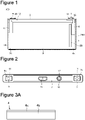
FIG. 1 is a front view illustrating a battery inner portion, excluding a front surface portion of a battery case and a front surface portion of an insulation sheet, of a secondary battery according to an embodiment. -
FIG. 2 is a top view of the secondary battery according to the embodiment. -
FIG. 3A is a plan view of a positive electrode plate according to the embodiment. -
FIG. 3B is a plan view of a negative electrode plate according to the embodiment. -
FIG. 4 is a diagram illustrating a method of sandwiching a wound positive electrode core exposure part and a positive electrode current collector with a horn and an anvil when ultrasonic welding is performed in a process for manufacturing the secondary battery according to the embodiment. -
FIG. 5 is a sectional view in the vicinity of an outermost periphery of the wound positive electrode core exposure part in a wound electrode assembly according to the embodiment and is a sectional view in a direction along a winding axis of the wound electrode assembly. -
FIG. 6 is a plan view of a tape according to the embodiment. -
FIG. 7A is a plan view of a flat-shaped wound electrode assembly according to the embodiment. -
FIG. 7B is a side view of the flat-shaped wound electrode assembly according to the embodiment. -
FIG. 8 is a sectional view in the vicinity of the outermost periphery of a wound positive electrode core exposure part in a wound electrode assembly according to another embodiment and is a sectional view in a direction along a winding axis of the wound electrode assembly. -
FIG. 9 is a sectional view in the vicinity of the outermost periphery of the wound positive electrode core exposure part in the wound electrode assembly without the tape attached thereto and is a sectional view in the direction along the winding axis of the wound electrode assembly. - A secondary battery according to an embodiment of the present disclosure will be described with reference to the drawings. The scope of the present invention is not limited to embodiments, described below, but can be arbitrarily changed within the scope of the technical idea of the present invention.
- First, a configuration of a rectangular secondary battery as the secondary battery according to the embodiment will be described.
- As illustrated in
FIG. 1 and FIG. 2 , a rectangularsecondary battery 100 comprises arectangular exterior member 1 having an opening at its top and asealing plate 2 that seals the opening. Therectangular exterior member 1 and thesealing plate 2 constitute abattery case 200. Each of therectangular exterior member 1 and thesealing plate 2 is made of a metal, and can be made of aluminum or an aluminum alloy, for example. A flat-shapedwound electrode assembly 3 in which a strip-shaped positive electrode plate and a strip-shaped negative electrode plate are wound with a strip-shaped separator sandwiched therebetween, together with an non-aqueous electrolyte, is housed in the rectangularexterior member 1. The positive electrode plate has a positive electrode active material layer containing a positive electrode active material formed on its positive electrode core made of a metal. The positive electrode plate has a positive electrode core exposure part, to which the positive electrode core is exposed, formed in its longitudinal direction. The negative electrode plate has a negative electrode active material layer containing a negative electrode active material formed on its negative electrode core made of a metal. The negative electrode plate has a negative electrode core exposure part, to which the negative electrode core is exposed, formed in its longitudinal direction. The positive electrode core can be made of aluminum or an aluminum alloy, for example. The negative electrode core can be made of copper or a copper alloy, for example. - In the
wound electrode assembly 3, a positive electrodecore exposure part 4c that is a positive electrode core having no positive electrode active material layer formed thereon is arranged in a wound state on one end side in a direction in which a winding axis of thewound electrode assembly 3 extends. The positive electrodecore exposure part 4c enters a laminated state by being wound with neither a separator nor a negative electrode plate interposed therebetween. A positive electrodecurrent collector 6 is connected to the wound positive electrodecore exposure part 4c. The positive electrodecurrent collector 6 can be made of aluminum or an aluminum alloy, for example. - In the
wound electrode assembly 3, a negative electrodecore exposure part 5c that is a negative electrode core having no negative electrode active material layer formed thereon is arranged in a wound state on the other end side in the direction in which the winding axis of thewound electrode assembly 3 extends. The negative electrodecore exposure part 5c enters a laminated state by being wound with neither a separator nor a positive electrode plate interposed therebetween. A negative electrodecurrent collector 8 is connected to the wound negative electrodecore exposure part 5c. The negative electrodecurrent collector 8 can be made of copper or a copper alloy, for example. - A
tape 30 is attached to span aseparator 20 positioned on an outermost surface of thewound electrode assembly 3 and an outermost surface of the wound positive electrodecore exposure part 4c. - A
positive electrode terminal 7 includes aflange portion 7a arranged on the battery outer side of the sealingplate 2 and an insertion part to be inserted into a through hole provided in the sealingplate 2. Thepositive electrode terminal 7 is made of a metal, and can be made of aluminum or an aluminum alloy, for example. Anegative electrode terminal 9 includes aflange portion 9a arranged on the battery outer side of the sealingplate 2 and an insertion part to be inserted into a through hole provided in the sealingplate 2. Thenegative electrode terminal 9 is made of a metal, and can be made of copper or a copper alloy, for example. Thenegative electrode terminal 9 may have a portion made of aluminum or an aluminum alloy and a portion made of copper or a copper alloy. In this case, the portion made of aluminum or an aluminum alloy preferably protrudes more outwardly than the sealingplate 2, and the portion made of copper or a copper alloy is preferably connected to the negative electrodecurrent collector 8. - The positive electrode
current collector 6 is fixed to the sealingplate 2 with an inner-side insulating member 10 made of resin sandwiched therebetween, and thepositive electrode terminal 7 is fixed to the sealingplate 2 with an outer-side insulating member 11 made of resin sandwiched therebetween. The negative electrodecurrent collector 8 is fixed to the sealingplate 2 with an inner-side insulating member 12 made of resin sandwiched therebetween, and thenegative electrode terminal 9 is fixed to the sealingplate 2 with an outer-side insulating member 13 made of resin sandwiched therebetween. - The
wound electrode assembly 3 is housed in therectangular exterior member 1 with it being covered with aninsulation sheet 14. The sealingplate 2 is welded and connected to an opening edge of therectangular exterior member 1 by laser welding or the like. The sealingplate 2 includes an electrolyticsolution injection hole 16. After injecting an electrolytic solution into therectangular exterior member 1, the electrolyticsolution injection hole 16 is sealed by a sealingplug 17. Agas exhaust vent 15 for exhausting a gas when a pressure in thebattery case 200 reaches a predetermined value or more is formed in the sealingplate 2. - Details of each of components will be described below.
- First, a method of manufacturing a positive electrode plate will be described.
- A lithium-nickel-cobalt-manganese composite oxide as a positive electrode active material, polyvinylidene fluoride (PVdF) as a binder, a carbon material as a conductive agent, and N-methyl-2-pyrrolidone (NMP) as a dispersion medium are kneaded such that a mass ratio of the lithium-nickel-cobalt-manganese composite oxide, the PVdF, and the carbon material is 97.5 : 1 : 1.5, to produce a positive electrode active material layer slurry.
- The positive electrode active material layer slurry produced in the above-described method is applied to both surfaces of an aluminum foil having a thickness of 15 µm as a positive electrode core with a die coater. The positive electrode core coated with the positive electrode active material layer slurry is dried, to remove the NMP in the slurry. As a result, a positive electrode active material layer is formed. Then, the positive electrode active material layer is compressed by a pair of press rollers, to obtain a positive electrode original plate. The positive electrode original plate is cut to have a predetermined size.
-
FIG. 3A is a plan view of apositive electrode plate 4. Positive electrodeactive material layers 4b are respectively formed on both surfaces of apositive electrode core 4a. The positive electrodecore exposure part 4c, to which thepositive electrode core 4a is exposed, is provided in a longitudinal direction of thepositive electrode plate 4 in one end portion in a width direction of thepositive electrode plate 4. - Then, a method of manufacturing a negative electrode plate will be described.
- Graphite as a negative electrode active material, styrene-butadiene rubber (SBR) and carboxymethyl cellulose (CMC) as a binder, and water as a dispersion medium are kneaded such that a mass ratio of the graphite, the SBR, and the CMC is 98 : 1 : 1, to produce a negative electrode active material layer slurry.
- The negative electrode active material layer slurry produced in the above-described method is applied to both surfaces of a copper foil having a thickness of 8 µm as a negative electrode core with a die coater. The negative electrode core coated with the negative electrode active material layer slurry is dried, to remove the water in the slurry. As a result, a negative electrode active material layer is formed. Then, the negative electrode active material layer is compressed by a pair of press rollers, to obtain a negative electrode original plate. The negative electrode original plate is cut to have a predetermined size.
-
FIG. 3B is a plan view of anegative electrode plate 5. Negative electrodeactive material layers 5b are respectively formed on both surfaces of anegative electrode core 5a. The negative electrodecore exposure part 5c, to which thenegative electrode core 5a is exposed, is provided in a longitudinal direction of thenegative electrode plate 5 in one end portion in a width direction of thenegative electrode plate 5. - The
positive electrode plate 4 and thenegative electrode plate 5 obtained in the above-described method are wound with theseparator 20 made of polyethylene, for example, interposed therebetween, and is shaped in a flat shape. As a result, the flat-shapedwound electrode assembly 3 having the wound positive electrodecore exposure part 4c at its one end portion and having the wound negative electrodecore exposure part 5c at its other end portion is obtained. - A method of mounting the positive electrode
current collector 6, thepositive electrode terminal 7, the negative electrodecurrent collector 8, and thenegative electrode terminal 9 on the sealingplate 2 will be described below. - First, the outer-
side insulating member 11 is arranged on the battery outer side of the sealingplate 2, and the inner-side insulating member 10 and the positive electrodecurrent collector 6 are arranged on the battery inner side of the sealingplate 2. Then, the insertion part in thepositive electrode terminal 7 is inserted into a through hole provided in each of the outer-side insulating member 11, the sealingplate 2, the inner-side insulating member 10, and the positive electrodecurrent collector 6 from the battery outer side, to caulk the distal end side of the insertion part in thepositive electrode terminal 7 onto the positive electrodecurrent collector 6. As a result, thepositive electrode terminal 7, the outer-side insulating member 11, the sealingplate 2, the inner-side insulating member 10, and the positive electrodecurrent collector 6 are integrally fixed. A caulked portion at a distal end of the insertion part in thepositive electrode terminal 7 is preferably welded to the positive electrodecurrent collector 6. - Similarly, the outer-
side insulating member 13 is arranged on the battery outer side of the sealingplate 2, and the inner-side insulating member 12 and the negative electrodecurrent collector 8 are arranged on the battery inner side of the sealingplate 2. Then, the insertion part in thenegative electrode terminal 9 is inserted into a through hole provided in each of the outer-side insulating member 13, the sealingplate 2, the inner-side insulating member 12, and the negative electrodecurrent collector 8 from the battery outer side, to caulk the distal end side of the insertion part in thenegative electrode terminal 9 onto the negative electrodecurrent collector 8. As a result, thenegative electrode terminal 9, the outer-side insulating member 13, the sealingplate 2, the inner-side insulating member 12, and the negative electrodecurrent collector 8 are integrally fixed. A caulked portion at a distal end of the insertion part in thenegative electrode terminal 9 is preferably welded to the negative electrodecurrent collector 8. - The positive electrode
current collector 6 is arranged on an outer surface of the positive electrodecore exposure part 4c that are laminated by being wound. The laminated positive electrodecore exposure part 4c and the positive electrodecurrent collector 6 are sandwiched with ahorn 90 and ananvil 91 in an ultrasonic bonding device to perform ultrasonic bonding, as illustrated inFIG. 4 . As a result, the wound positive electrodecore exposure part 4c and the positive electrodecurrent collector 6 are connected to each other. The negative electrodecore exposure part 5c laminated by being wound and the negative electrodecurrent collector 8 can also be connected to each other in a similar method. A connection method is not limited to ultrasonic bonding, but may use resistance welding or laser welding. -
FIG. 9 is a sectional view in the vicinity of the outermost surface of the wound positive electrodecore exposure part 4c in thewound electrode assembly 3.FIG. 9 is a sectional view in a direction along the winding axis of thewound electrode assembly 3.FIG. 9 is a diagram illustrating a state where thetape 30 has not been attached to thewound electrode assembly 3. Theseparator 20 is arranged on the outermost periphery of thewound electrode assembly 3. In thewound electrode assembly 3, a layer in thenegative electrode plate 5 positioned on the outermost periphery side is positioned closer to the outermost periphery of thewound electrode assembly 3 than a layer in thepositive electrode plate 4 positioned on the outermost periphery side. - The positive electrode
core exposure part 4c laminated by being wound is bundled and connected to the positive electrodecurrent collector 6, although partially omitted inFIG. 9 . In the secondary battery comprising thewound electrode assembly 3, if an electrolytic solution is injected into thebattery case 200, aforeign substance 80, together with the electrolytic solution, enters a space between thepositive electrode plate 4 and theseparator 20 or between thenegative electrode plate 5 and theseparator 20, as illustrated inFIG. 9 , so that an internal short circuit may occur. - To suppress such an internal short circuit, when a tape is attached to the outermost surface of the positive electrode
core exposure part 4c from theseparator 20 positioned on the outermost periphery of thewound electrode assembly 3, the foreign substance can be prevented from entering thewound electrode assembly 3. However, the electrolytic solution does not easily enter thewound electrode assembly 3. A portion where the electrolytic solution is insufficient occurs in thewound electrode assembly 3 so that charge-discharge reaction may be non-uniform or a lithium metal may be deposited. - The
tape 30 is attached to the outermost surface of the wound positive electrodecore exposure part 4c, starting from theseparator 20 positioned on the outermost surface of the flat-shapedwound electrode assembly 3, as illustrated inFIG. 5 . Thetape 30 includes aporous base material 30a and anadhesive layer 30b provided on one surface of thebase material 30a. - As illustrated in
FIG. 6 , twoadhesive layers 30b are provided in a longitudinal direction of thetape 30 on one surface of thebase material 30a. The twoadhesive layers 30b are provided away from each other in a width direction of thetape 30. - As illustrated in
FIG. 5 , theseparator 20 is arranged on the outermost peripheral surface of thewound electrode assembly 3. In thewound electrode assembly 3, the layer positioned on the outermost periphery side of thewound electrode assembly 3 in thenegative electrode plate 5 is positioned closer to the outermost periphery of thewound electrode assembly 3 than the layer positioned on the outermost periphery side of thewound electrode assembly 3 in thepositive electrode plate 4. - The
base material 30a in thetape 30 is connected to theseparator 20 positioned on the outermost periphery of thewound electrode assembly 3 by theadhesive layer 30b. Thebase material 30a in thetape 30 is connected to the outermost surface of the positive electrodecore exposure part 4c wound by theadhesive layer 30b. Thebase material 30a is provided with a region where theadhesive layer 30b is not formed between a portion connected to theseparator 20 in thetape 30 and a portion connected to the positive electrodecore exposure part 4c in thetape 30. Thebase material 30a is a porous member through which an electrolytic solution can penetrate. Such a configuration prevents a foreign substance from entering thewound electrode assembly 3 without preventing the electrolytic solution from entering thewound electrode assembly 3. - A nonwoven fabric is particularly preferable as the
porous base material 30a. If thebase material 30a is a nonwoven fabric, a foreign substance can be effectively captured. The nonwoven fabric is preferably composed of fibers made of resin such as polyester, polyolefin, polyamide, polyurethane, or polystyrene, glass fibers, or fibers such as ceramic fibers or cellulose fibers. - The basis weight of the nonwoven fabric is preferably 40 to 100 g/m2. When the basis weight of the nonwoven fabric is set to 40 g/m2 or more, a foreign substance can be more effectively prevented from entering the
wound electrode assembly 3. When the basis weight of the nonwoven fabric is set to 100 g/m2 or less, an electrolytic solution can easily enter thewound electrode assembly 3. - The average fiber diameter of the fibers composing the nonwoven fabric is preferably 8 to 60 µm. When the average fiber diameter of the fibers is set to 8 µm or more, a foreign substance can be more effectively prevented from entering the
wound electrode assembly 3. When the average fiber diameter of the fibers is set to 60 µm or less, an electrolytic solution can easily enter thewound electrode assembly 3. The average fiber diameter of the fibers is a value obtained by selecting any ten portions on an image by SEM measurement and averaging the respective diameters of the 10 portions. - If a foreign substance having a diameter of 20 µm or more enters the
wound electrode assembly 3, an internal short circuit may occur. When the basis weight of the nonwoven fabric is set to 40 g/m2 or more, the foreign substance having a diameter of 20 µm or more can be more effectively prevented from entering thewound electrode assembly 3. When the average fiber diameter of the fibers composing the nonwoven fabric is set to 8 µm or more, the foreign substance having a diameter of 20 µm or more can be more effectively prevented from entering thewound electrode assembly 3. - As the
porous base material 30a, a porous polymeric film composed of polyolefin resin, fluorine resin, or the like, for example, can be used in addition to the nonwoven fabric. - As the
adhesive layer 30b, members selected from rubber-based adhesives, acrylic-based adhesives, polyethylene-based adhesives, and the like or their mixtures are preferably used. However, theadhesive layer 30b is not limited to these. - As illustrated in
FIG. 7A and FIG. 7B , the flat-shapedwound electrode assembly 3 includes aflat portion 3a having a substantially uniform thickness andcurved portions 3b respectively formed at both ends of theflat portion 3a. Each of thecurved portions 3b has a curved outer surface. - The length of the
flat portion 3a in a direction perpendicular to the winding axis of the wound electrode assembly 3 (a length in a longitudinal direction inFIG. 7A and FIG. 7B ) is defined as a length L1. At this time, a length L2 of a region to which thetape 30 is attached in thewound electrode assembly 3 is preferably set to 0.5 × L1 or more and more preferably 0.8 × L1 or more. - The
tape 30 is preferably attached to both outer surfaces of theflat portion 3a in thewound electrode assembly 3. In this case, onetape 30 can be attached to one outer surface of theflat portion 3a, and anothertape 30 can be attached to the other outer surface of theflat portion 3a. Alternatively, onetape 30 can be attached to span one outer surface of theflat portion 3a, thecurved portions 3b, and the other outer surface of theflat portion 3a. - Although an example in which the
tape 30 is attached to thewound electrode assembly 3 after the positive electrodecurrent collector 6 is connected to the positive electrodecore exposure part 4c has been described above, the positive electrodecurrent collector 6 may be connected to the positive electrodecore exposure part 4c after thetape 30 is attached to thewound electrode assembly 3. - As illustrated in
FIG. 5 , in the direction in which the winding axis of thewound electrode assembly 3 extends, a center-side end portion of thetape 30 is preferably arranged outside an outer-side end portion of thenegative electrode plate 5. That is, when thewound electrode assembly 3 is viewed in a direction in which thepositive electrode plate 4, theseparator 20, and thenegative electrode plate 5 are laminated in theflat portion 3a, thenegative electrode plate 5 and thetape 30 are preferably arranged not to overlap each other. As a result, when theseparator 20 is folded toward the center side (the lower side inFIG. 5 ) in the lamination direction, a portion having a large thickness can be prevented from partially occurring in theflat portion 3a in thewound electrode assembly 3. Thetape 30 may be arranged to overlap thenegative electrode plate 5. - The side of one end portion in the width direction of the
tape 30 is preferably connected to a region inclined in the positive electrodecore exposure part 4c by theadhesive layer 30b. - The width of the
base material 30a can be set to approximately 5 mm to 30 mm, for example, but is not limited to this. The width of theadhesive layer 30b can be set to approximately 2 to 10 mm, for example, but is not limited to this. The width of a region, where theadhesive layer 30b is not formed, provided between the twoadhesive layers 30b, in thebase material 30a can be set to approximately 1 to 25 mm, for example, but is not limited to this. - The
tape 30 may be arranged on an outer surface on the side on which the positive electrodecurrent collector 6 is not arranged in the wound positive electrodecore exposure part 4c. For example, thetape 30 can be attached before ultrasonic bonding to a portion, which contacts an anvil or a horn for ultrasonic bonding, on the outer surface of the wound positive electrodecore exposure part 4c. Thetape 30 can be attached after ultrasonic bonding to a portion, which contacts the anvil or the horn for ultrasonic bonding, on the outer surface of the wound positive electrodecore exposure part 4c. - As illustrated in
FIG. 8 , a part of atape 30 may be attached onto a positive electrodecurrent collector 6. In such a configuration, a foreign substance that has adhered onto the positive electrodecurrent collector 6 or a burr formed in the positive electrodecurrent collector 6, for example, can be kept on the positive electrodecurrent collector 6 with thetape 30. - After the
tape 30 is attached to aseparator 20 and a positive electrodecore exposure part 4c, the positive electrodecurrent collector 6 may be connected to the positive electrodecore exposure part 4c. - Known materials can be respectively used for a positive electrode plate, a negative electrode plate, a separator, an electrolyte, and the like.
-
- 100
- rectangular secondary battery
- 200
- battery case
- 1
- rectangular exterior member
- 2
- sealing plate
- 3
- wound electrode assembly
- 3a
- flat portion
- 3b
- curved portion
- 4
- positive electrode plate
- 4a
- positive electrode core
- 4b
- positive electrode active material layer
- 4c
- positive electrode core exposure part
- 5
- negative electrode plate
- 5a
- negative electrode core
- 5b
- negative electrode active material layer
- 5c
- negative electrode core exposure part
- 6
- positive electrode current collector
- 7
- positive electrode terminal
- 7a
- flange portion
- 8
- negative electrode current collector
- 9
- negative electrode terminal
- 9a
- flange portion
- 10
- inner-side insulating member
- 11
- outer-side insulating member
- 12
- inner-side insulating member
- 13
- outer-side insulating member
- 14
- insulation sheet
- 15
- gas exhaust vent
- 16
- electrolytic solution injection hole
- 17
- sealing plug
- 20
- separator
- 30
- tape
- 30a
- base material
- 30b
- adhesive layer
- 80
- foreign substance
- 90
- horn
- 91
- anvil
Claims (4)
- A secondary battery comprising:a first electrode plate in which a first electrode active material layer is formed on a first electrode core;a second electrode plate in which a second electrode active material layer is formed on a second electrode core; anda flat-shaped wound electrode assembly in which the first electrode plate and the second electrode plate are wound with a separator interposed therebetween, whereinthe wound electrode assembly includes a wound first electrode core exposure part at one end portion in a direction in which a winding axis of the wound electrode assembly extends, and includes a wound second electrode core exposure part at the other end portion in the direction in which the winding axis extends,the wound first electrode core exposure part is bundled and connected to a first electrode current collector,the separator is arranged on an outermost surface of the wound electrode assembly,a tape is attached to span the separator arranged on the outermost surface of the wound electrode assembly and an outermost surface of the wound first electrode core exposure part,the tape includes a porous base material and an adhesive layer provided on the base material, andthe tape includes a region where the adhesive layer is not provided on the base material, between an adhesion part between the tape and the separator arranged on the outermost surface of the wound electrode assembly and an adhesion part between the tape and the outermost surface of the wound first electrode core exposure part.
- The secondary battery according to claim 1, wherein the porous base material is a nonwoven fabric.
- The secondary battery according to claim 2, whereina basis weight of the nonwoven fabric is 40 to 100 g/m2, andan average fiber diameter of fibers composing the nonwoven fabric is 8 to 60 µm.
- The secondary battery according to any one of claims 1 to 3, wherein the first electrode plate is a positive electrode plate, and the second electrode plate is a negative electrode plate.
Applications Claiming Priority (2)
| Application Number | Priority Date | Filing Date | Title |
|---|---|---|---|
| JP2020038287 | 2020-03-06 | ||
| PCT/JP2021/004634 WO2021176961A1 (en) | 2020-03-06 | 2021-02-08 | Secondary battery |
Publications (3)
| Publication Number | Publication Date |
|---|---|
| EP4117065A1 true EP4117065A1 (en) | 2023-01-11 |
| EP4117065A4 EP4117065A4 (en) | 2024-05-15 |
| EP4117065B1 EP4117065B1 (en) | 2026-04-01 |
Family
ID=77614357
Family Applications (1)
| Application Number | Title | Priority Date | Filing Date |
|---|---|---|---|
| EP21764008.5A Active EP4117065B1 (en) | 2020-03-06 | 2021-02-08 | Secondary battery |
Country Status (5)
| Country | Link |
|---|---|
| US (1) | US12676334B2 (en) |
| EP (1) | EP4117065B1 (en) |
| JP (1) | JP7620614B2 (en) |
| CN (1) | CN115210932B (en) |
| WO (1) | WO2021176961A1 (en) |
Families Citing this family (3)
| Publication number | Priority date | Publication date | Assignee | Title |
|---|---|---|---|---|
| EP4220824A4 (en) * | 2021-09-29 | 2024-10-16 | Contemporary Amperex Technology (Hong Kong) Limited | Battery cell, battery, electric device, and method and device for manufacturing battery cell |
| JP7638245B2 (en) * | 2022-09-08 | 2025-03-03 | プライムプラネットエナジー&ソリューションズ株式会社 | Battery manufacturing method |
| WO2025229947A1 (en) * | 2024-04-30 | 2025-11-06 | パナソニックIpマネジメント株式会社 | Non-aqueous electrolyte secondary battery |
Family Cites Families (15)
| Publication number | Priority date | Publication date | Assignee | Title |
|---|---|---|---|---|
| JP4052537B2 (en) * | 1998-07-10 | 2008-02-27 | 日立マクセル株式会社 | Non-aqueous secondary battery |
| JP4387951B2 (en) | 2002-10-24 | 2009-12-24 | ダイワボウホールディングス株式会社 | Separator for organic electrolyte battery, manufacturing method thereof, and organic electrolyte battery incorporating the same |
| KR100601551B1 (en) * | 2004-09-06 | 2006-07-19 | 삼성에스디아이 주식회사 | Electrode Assembly and Lithium Secondary Battery Using the Same |
| JP4568123B2 (en) * | 2005-01-12 | 2010-10-27 | 三洋電機株式会社 | Non-aqueous electrolyte battery |
| KR100686813B1 (en) | 2005-04-26 | 2007-02-26 | 삼성에스디아이 주식회사 | Secondary battery |
| JP2007073317A (en) * | 2005-09-07 | 2007-03-22 | Gs Yuasa Corporation:Kk | Winding power generation element and battery |
| JP5439317B2 (en) | 2010-08-30 | 2014-03-12 | 日立ビークルエナジー株式会社 | Secondary battery |
| JP2013077484A (en) * | 2011-09-30 | 2013-04-25 | Sanyo Electric Co Ltd | Secondary battery |
| CN104247090B (en) | 2012-01-19 | 2017-10-31 | 索尼公司 | Separators, non-aqueous electrolyte batteries, battery packs, electronic equipment, electric vehicles, power storage devices, and power systems |
| JP6156392B2 (en) * | 2012-12-06 | 2017-07-05 | 株式会社村田製作所 | Battery and assembled battery using the same |
| US9685646B2 (en) * | 2013-10-03 | 2017-06-20 | Johns Manville | Pasting paper made of glass fiber nonwoven comprising carbon graphite |
| CN106030890B (en) * | 2014-03-27 | 2019-03-12 | 三洋电机株式会社 | Non-aqueous electrolyte secondary battery and method for producing the same |
| JP6682758B2 (en) * | 2014-11-25 | 2020-04-15 | 株式会社Gsユアサ | Storage element |
| KR102580234B1 (en) * | 2016-02-22 | 2023-09-19 | 삼성에스디아이 주식회사 | Rechargeable battery |
| KR102845477B1 (en) * | 2018-12-03 | 2025-08-13 | 주식회사 엘지에너지솔루션 | Electrode for a secondary battery, secondary battery and flexible secondary battery including the same |
-
2021
- 2021-02-08 EP EP21764008.5A patent/EP4117065B1/en active Active
- 2021-02-08 JP JP2022505070A patent/JP7620614B2/en active Active
- 2021-02-08 WO PCT/JP2021/004634 patent/WO2021176961A1/en not_active Ceased
- 2021-02-08 US US17/909,416 patent/US12676334B2/en active Active
- 2021-02-08 CN CN202180018884.1A patent/CN115210932B/en active Active
Also Published As
| Publication number | Publication date |
|---|---|
| EP4117065B1 (en) | 2026-04-01 |
| US20230087148A1 (en) | 2023-03-23 |
| CN115210932A (en) | 2022-10-18 |
| WO2021176961A1 (en) | 2021-09-10 |
| CN115210932B (en) | 2025-04-25 |
| JPWO2021176961A1 (en) | 2021-09-10 |
| US12676334B2 (en) | 2026-07-07 |
| JP7620614B2 (en) | 2025-01-23 |
| EP4117065A4 (en) | 2024-05-15 |
Similar Documents
| Publication | Publication Date | Title |
|---|---|---|
| US11437619B2 (en) | Secondary battery, insulating member and positive electrode lead | |
| CN110429320B (en) | Winding type battery | |
| US10069118B2 (en) | Cylindrical secondary battery and method for manufacturing same | |
| KR101738279B1 (en) | Secondary battery comprising current interrupt device | |
| US20110217576A1 (en) | Wound electrode assembly and battery | |
| JP5194070B2 (en) | Secondary battery | |
| US11824166B2 (en) | Secondary battery | |
| US12308394B2 (en) | Rectangular secondary battery | |
| JP6862919B2 (en) | Square lithium ion secondary battery | |
| EP4117065B1 (en) | Secondary battery | |
| US12176530B2 (en) | Electrode plate and method for manufacturing same, and secondary battery and method for manufacturing same | |
| EP4641745A1 (en) | Nonaqueous electrolyte secondary battery | |
| JP5590410B2 (en) | Cylindrical secondary battery | |
| US12548860B2 (en) | Electrode plate for secondary cell, and secondary cell using same | |
| JP5334109B2 (en) | Laminated battery | |
| JP2012049073A (en) | Secondary battery | |
| JP2010244865A (en) | Laminated battery | |
| JP2001126769A (en) | Cylindrical lithium-ion battery | |
| JP2024539757A (en) | Energy storage element and manufacturing process | |
| EP4641744A1 (en) | Nonaqueous electrolyte secondary battery | |
| JP2011108538A (en) | Laminate battery | |
| JP3511966B2 (en) | Cylindrical lithium-ion battery | |
| JP5377472B2 (en) | Lithium ion secondary battery | |
| US20240097197A1 (en) | Non-aqueous rechargeable battery | |
| EP4700870A1 (en) | Power storage device |
Legal Events
| Date | Code | Title | Description |
|---|---|---|---|
| STAA | Information on the status of an ep patent application or granted ep patent |
Free format text: STATUS: THE INTERNATIONAL PUBLICATION HAS BEEN MADE |
|
| PUAI | Public reference made under article 153(3) epc to a published international application that has entered the european phase |
Free format text: ORIGINAL CODE: 0009012 |
|
| STAA | Information on the status of an ep patent application or granted ep patent |
Free format text: STATUS: REQUEST FOR EXAMINATION WAS MADE |
|
| 17P | Request for examination filed |
Effective date: 20220929 |
|
| AK | Designated contracting states |
Kind code of ref document: A1 Designated state(s): AL AT BE BG CH CY CZ DE DK EE ES FI FR GB GR HR HU IE IS IT LI LT LU LV MC MK MT NL NO PL PT RO RS SE SI SK SM TR |
|
| DAV | Request for validation of the european patent (deleted) | ||
| DAX | Request for extension of the european patent (deleted) | ||
| REG | Reference to a national code |
Ref country code: DE Ref legal event code: R079 Free format text: PREVIOUS MAIN CLASS: H01M0010040000 Ipc: H01M0050586000 Ref country code: DE Ref legal event code: R079 Ref document number: 602021051190 Country of ref document: DE Free format text: PREVIOUS MAIN CLASS: H01M0010040000 Ipc: H01M0050586000 |
|
| A4 | Supplementary search report drawn up and despatched |
Effective date: 20240416 |
|
| RIC1 | Information provided on ipc code assigned before grant |
Ipc: H01M 50/477 20210101ALI20240410BHEP Ipc: H01M 50/566 20210101ALI20240410BHEP Ipc: H01M 50/557 20210101ALI20240410BHEP Ipc: H01M 50/538 20210101ALI20240410BHEP Ipc: H01M 50/48 20210101ALI20240410BHEP Ipc: H01M 50/474 20210101ALI20240410BHEP Ipc: H01M 10/42 20060101ALI20240410BHEP Ipc: H01M 10/052 20100101ALI20240410BHEP Ipc: H01M 10/04 20060101ALI20240410BHEP Ipc: H01M 10/0587 20100101ALI20240410BHEP Ipc: H01M 50/595 20210101ALI20240410BHEP Ipc: H01M 50/586 20210101AFI20240410BHEP |
|
| GRAP | Despatch of communication of intention to grant a patent |
Free format text: ORIGINAL CODE: EPIDOSNIGR1 |
|
| STAA | Information on the status of an ep patent application or granted ep patent |
Free format text: STATUS: GRANT OF PATENT IS INTENDED |
|
| INTG | Intention to grant announced |
Effective date: 20250722 |
|
| RIN1 | Information on inventor provided before grant (corrected) |
Inventor name: TAKABAYASHI, HIROSHI Inventor name: KAI, RYUHEI |
|
| GRAJ | Information related to disapproval of communication of intention to grant by the applicant or resumption of examination proceedings by the epo deleted |
Free format text: ORIGINAL CODE: EPIDOSDIGR1 |
|
| STAA | Information on the status of an ep patent application or granted ep patent |
Free format text: STATUS: REQUEST FOR EXAMINATION WAS MADE |
|
| GRAP | Despatch of communication of intention to grant a patent |
Free format text: ORIGINAL CODE: EPIDOSNIGR1 |
|
| STAA | Information on the status of an ep patent application or granted ep patent |
Free format text: STATUS: GRANT OF PATENT IS INTENDED |
|
| INTC | Intention to grant announced (deleted) | ||
| INTG | Intention to grant announced |
Effective date: 20251216 |
|
| GRAS | Grant fee paid |
Free format text: ORIGINAL CODE: EPIDOSNIGR3 |
|
| GRAA | (expected) grant |
Free format text: ORIGINAL CODE: 0009210 |
|
| STAA | Information on the status of an ep patent application or granted ep patent |
Free format text: STATUS: THE PATENT HAS BEEN GRANTED |
|
| AK | Designated contracting states |
Kind code of ref document: B1 Designated state(s): AL AT BE BG CH CY CZ DE DK EE ES FI FR GB GR HR HU IE IS IT LI LT LU LV MC MK MT NL NO PL PT RO RS SE SI SK SM TR |
|
| REG | Reference to a national code |
Ref country code: CH Ref legal event code: F10 Free format text: ST27 STATUS EVENT CODE: U-0-0-F10-F00 (AS PROVIDED BY THE NATIONAL OFFICE) Effective date: 20260401 Ref country code: GB Ref legal event code: FG4D |
|
| REG | Reference to a national code |
Ref country code: IE Ref legal event code: FG4D |
|
| REG | Reference to a national code |
Ref country code: DE Ref legal event code: R096 Ref document number: 602021051190 Country of ref document: DE |
|
| REG | Reference to a national code |
Ref country code: NL Ref legal event code: MP Effective date: 20260401 |