EP4117055A1 - Method for manufacturing anode having inorganic coating layer formed thereon - Google Patents
Method for manufacturing anode having inorganic coating layer formed thereon Download PDFInfo
- Publication number
- EP4117055A1 EP4117055A1 EP21883067.7A EP21883067A EP4117055A1 EP 4117055 A1 EP4117055 A1 EP 4117055A1 EP 21883067 A EP21883067 A EP 21883067A EP 4117055 A1 EP4117055 A1 EP 4117055A1
- Authority
- EP
- European Patent Office
- Prior art keywords
- negative electrode
- active material
- electrode active
- lithium
- material layer
- Prior art date
- Legal status (The legal status is an assumption and is not a legal conclusion. Google has not performed a legal analysis and makes no representation as to the accuracy of the status listed.)
- Granted
Links
Images


Classifications
-
- H—ELECTRICITY
- H01—ELECTRIC ELEMENTS
- H01M—PROCESSES OR MEANS, e.g. BATTERIES, FOR THE DIRECT CONVERSION OF CHEMICAL ENERGY INTO ELECTRICAL ENERGY
- H01M4/00—Electrodes
- H01M4/02—Electrodes composed of, or comprising, active material
- H01M4/04—Processes of manufacture in general
- H01M4/0402—Methods of deposition of the material
- H01M4/0404—Methods of deposition of the material by coating on electrode collectors
-
- H—ELECTRICITY
- H01—ELECTRIC ELEMENTS
- H01M—PROCESSES OR MEANS, e.g. BATTERIES, FOR THE DIRECT CONVERSION OF CHEMICAL ENERGY INTO ELECTRICAL ENERGY
- H01M4/00—Electrodes
- H01M4/02—Electrodes composed of, or comprising, active material
- H01M4/36—Selection of substances as active materials, active masses, active liquids
- H01M4/362—Composites
- H01M4/366—Composites as layered products
-
- H—ELECTRICITY
- H01—ELECTRIC ELEMENTS
- H01M—PROCESSES OR MEANS, e.g. BATTERIES, FOR THE DIRECT CONVERSION OF CHEMICAL ENERGY INTO ELECTRICAL ENERGY
- H01M4/00—Electrodes
- H01M4/02—Electrodes composed of, or comprising, active material
- H01M4/13—Electrodes for accumulators with non-aqueous electrolyte, e.g. for lithium-accumulators; Processes of manufacture thereof
- H01M4/139—Processes of manufacture
-
- H—ELECTRICITY
- H01—ELECTRIC ELEMENTS
- H01M—PROCESSES OR MEANS, e.g. BATTERIES, FOR THE DIRECT CONVERSION OF CHEMICAL ENERGY INTO ELECTRICAL ENERGY
- H01M4/00—Electrodes
- H01M4/02—Electrodes composed of, or comprising, active material
- H01M4/04—Processes of manufacture in general
- H01M4/0438—Processes of manufacture in general by electrochemical processing
- H01M4/044—Activating, forming or electrochemical attack of the supporting material
- H01M4/0445—Forming after manufacture of the electrode, e.g. first charge, cycling
-
- H—ELECTRICITY
- H01—ELECTRIC ELEMENTS
- H01M—PROCESSES OR MEANS, e.g. BATTERIES, FOR THE DIRECT CONVERSION OF CHEMICAL ENERGY INTO ELECTRICAL ENERGY
- H01M4/00—Electrodes
- H01M4/02—Electrodes composed of, or comprising, active material
- H01M4/04—Processes of manufacture in general
- H01M4/0438—Processes of manufacture in general by electrochemical processing
- H01M4/0459—Electrochemical doping, intercalation, occlusion or alloying
-
- H—ELECTRICITY
- H01—ELECTRIC ELEMENTS
- H01M—PROCESSES OR MEANS, e.g. BATTERIES, FOR THE DIRECT CONVERSION OF CHEMICAL ENERGY INTO ELECTRICAL ENERGY
- H01M4/00—Electrodes
- H01M4/02—Electrodes composed of, or comprising, active material
- H01M4/04—Processes of manufacture in general
- H01M4/049—Manufacturing of an active layer by chemical means
-
- H—ELECTRICITY
- H01—ELECTRIC ELEMENTS
- H01M—PROCESSES OR MEANS, e.g. BATTERIES, FOR THE DIRECT CONVERSION OF CHEMICAL ENERGY INTO ELECTRICAL ENERGY
- H01M4/00—Electrodes
- H01M4/02—Electrodes composed of, or comprising, active material
- H01M4/13—Electrodes for accumulators with non-aqueous electrolyte, e.g. for lithium-accumulators; Processes of manufacture thereof
-
- H—ELECTRICITY
- H01—ELECTRIC ELEMENTS
- H01M—PROCESSES OR MEANS, e.g. BATTERIES, FOR THE DIRECT CONVERSION OF CHEMICAL ENERGY INTO ELECTRICAL ENERGY
- H01M4/00—Electrodes
- H01M4/02—Electrodes composed of, or comprising, active material
- H01M4/36—Selection of substances as active materials, active masses, active liquids
- H01M4/38—Selection of substances as active materials, active masses, active liquids of elements or alloys
- H01M4/381—Alkaline or alkaline earth metals elements
- H01M4/382—Lithium
-
- H—ELECTRICITY
- H01—ELECTRIC ELEMENTS
- H01M—PROCESSES OR MEANS, e.g. BATTERIES, FOR THE DIRECT CONVERSION OF CHEMICAL ENERGY INTO ELECTRICAL ENERGY
- H01M4/00—Electrodes
- H01M4/02—Electrodes composed of, or comprising, active material
- H01M4/36—Selection of substances as active materials, active masses, active liquids
- H01M4/38—Selection of substances as active materials, active masses, active liquids of elements or alloys
- H01M4/386—Silicon or alloys based on silicon
-
- H—ELECTRICITY
- H01—ELECTRIC ELEMENTS
- H01M—PROCESSES OR MEANS, e.g. BATTERIES, FOR THE DIRECT CONVERSION OF CHEMICAL ENERGY INTO ELECTRICAL ENERGY
- H01M4/00—Electrodes
- H01M4/02—Electrodes composed of, or comprising, active material
- H01M4/36—Selection of substances as active materials, active masses, active liquids
- H01M4/48—Selection of substances as active materials, active masses, active liquids of inorganic oxides or hydroxides
-
- H—ELECTRICITY
- H01—ELECTRIC ELEMENTS
- H01M—PROCESSES OR MEANS, e.g. BATTERIES, FOR THE DIRECT CONVERSION OF CHEMICAL ENERGY INTO ELECTRICAL ENERGY
- H01M4/00—Electrodes
- H01M4/02—Electrodes composed of, or comprising, active material
- H01M4/62—Selection of inactive substances as ingredients for active masses, e.g. binders, fillers
-
- H—ELECTRICITY
- H01—ELECTRIC ELEMENTS
- H01M—PROCESSES OR MEANS, e.g. BATTERIES, FOR THE DIRECT CONVERSION OF CHEMICAL ENERGY INTO ELECTRICAL ENERGY
- H01M10/00—Secondary cells; Manufacture thereof
- H01M10/05—Accumulators with non-aqueous electrolyte
- H01M10/052—Li-accumulators
-
- H—ELECTRICITY
- H01—ELECTRIC ELEMENTS
- H01M—PROCESSES OR MEANS, e.g. BATTERIES, FOR THE DIRECT CONVERSION OF CHEMICAL ENERGY INTO ELECTRICAL ENERGY
- H01M4/00—Electrodes
- H01M4/02—Electrodes composed of, or comprising, active material
- H01M2004/026—Electrodes composed of, or comprising, active material characterised by the polarity
- H01M2004/027—Negative electrodes
-
- Y—GENERAL TAGGING OF NEW TECHNOLOGICAL DEVELOPMENTS; GENERAL TAGGING OF CROSS-SECTIONAL TECHNOLOGIES SPANNING OVER SEVERAL SECTIONS OF THE IPC; TECHNICAL SUBJECTS COVERED BY FORMER USPC CROSS-REFERENCE ART COLLECTIONS [XRACs] AND DIGESTS
- Y02—TECHNOLOGIES OR APPLICATIONS FOR MITIGATION OR ADAPTATION AGAINST CLIMATE CHANGE
- Y02E—REDUCTION OF GREENHOUSE GAS [GHG] EMISSIONS, RELATED TO ENERGY GENERATION, TRANSMISSION OR DISTRIBUTION
- Y02E60/00—Enabling technologies; Technologies with a potential or indirect contribution to GHG emissions mitigation
- Y02E60/10—Energy storage using batteries
-
- Y—GENERAL TAGGING OF NEW TECHNOLOGICAL DEVELOPMENTS; GENERAL TAGGING OF CROSS-SECTIONAL TECHNOLOGIES SPANNING OVER SEVERAL SECTIONS OF THE IPC; TECHNICAL SUBJECTS COVERED BY FORMER USPC CROSS-REFERENCE ART COLLECTIONS [XRACs] AND DIGESTS
- Y02—TECHNOLOGIES OR APPLICATIONS FOR MITIGATION OR ADAPTATION AGAINST CLIMATE CHANGE
- Y02P—CLIMATE CHANGE MITIGATION TECHNOLOGIES IN THE PRODUCTION OR PROCESSING OF GOODS
- Y02P70/00—Climate change mitigation technologies in the production process for final industrial or consumer products
- Y02P70/50—Manufacturing or production processes characterised by the final manufactured product
Definitions
- the present invention relates to a method of manufacturing a negative electrode, and a negative electrode manufactured by the method of manufacturing a negative electrode, and more specifically, to a method of manufacturing a negative electrode having an inorganic coating layer formed thereon, and a negative electrode manufactured by the method.
- secondary batteries capable of charging and discharging have been widely used as energy sources of wireless mobile devices.
- the secondary battery has attracted attention as an energy source of an electric vehicle, a hybrid electric vehicle, etc., which are proposed as a solution for air pollution of existing gasoline vehicles and diesel vehicles using fossil fuel. Therefore, the types of applications using the secondary battery are currently much diversified due to the advantages of the secondary battery, and it is expected that the secondary battery will be applied to many fields and products in the future.
- Such secondary batteries may be classified into lithium ion batteries, lithium ion polymer batteries, lithium polymer batteries, etc., depending on the composition of the electrode and the electrolyte, and among them, the amount of use of lithium-ion polymer batteries that are less likely to leak electrolyte and are easy to manufacture is on the increase.
- secondary batteries are classified into cylindrical batteries and prismatic batteries in which an electrode assembly is embedded in a cylindrical or rectangular metal can, depending on the shape of a battery case, and pouch-type batteries in which the electrode assembly is embedded in a pouch-type case of an aluminum laminate sheet.
- the electrode assembly built into the battery case is composed of a positive electrode, a negative electrode, and a separator interposed between the positive electrode and the negative electrode, and is a power generating element capable of charging and discharging.
- the electrode assembly is classified into a jelly-roll type wound with a separator interposed between the positive electrode and the negative electrode which are long sheet-shaped and are coated with active materials, and a stack type in which a plurality of positive electrodes and negative electrodes of a predetermined size are sequentially stacked while a separator is interposed therebetween.
- the positive electrode and the negative electrode are formed by applying a positive electrode slurry containing a positive electrode active material and a negative electrode slurry containing a negative electrode active material to a positive electrode current collector and a negative electrode current collector, to thereby form a positive electrode active material layer and a negative electrode active material layer, respectively, followed by drying and rolling them.
- a passive film such as a solid electrolyte interface (SEI) layer is formed on the surface of the negative electrode during the initial charge.
- SEI solid electrolyte interface
- the passive film interrupts injection of the organic solvent into the negative electrode and suppresses decomposition reaction of the organic solvent, thereby stabilizing the structure of the negative electrode, improving the reversibility of the negative electrode, and allowing the negative electrode to be usable.
- the formation reaction of the passive film is an irreversible reaction, the consumption of the lithium ions is caused, thereby decreasing the capacity of the battery, and as the battery cycle is repeated, the lithium ions are consumed, thereby causing capacity reduction and cycle lifespan reduction.
- Such a pre-lithiation method includes a physical method of allowing lithium metal to directly contact the surface of the negative electrode, and a method of connecting lithium metal with the negative electrode and electrochemically charging the negative electrode.
- an aspect of the present invention provides a method of manufacturing a negative electrode capable of suppressing the loss of lithium caused by redox reaction between the negative electrode and air and the moisture in the air, and a negative electrode manufactured by the method.
- a method of manufacturing a negative electrode according to the present invention includes: manufacturing a negative electrode having a negative electrode active material layer formed thereon by coating a negative electrode slurry including a negative electrode active material at least on one surface of a current collector; pre-lithiating the negative electrode; and forming an inorganic coating layer on a surface of the negative electrode active material layer by aging the pre-lithiated negative electrode under an CO 2 atmosphere.
- the inorganic coating layer includes one or more compounds selected from the group consisting of Li 2 O, LiOH and Li 2 CO 3 .
- the inorganic coating layer may include all of Li 2 O, LiOH and Li 2 CO 3 .
- the negative electrode active material may be one or more selected from the group consisting of a graphite-based active material and a silicon-based active material.
- the pre-lithiating of the negative electrode may be performed by directly contacting a lithium metal on the negative electrode active material layer.
- the pre-lithiating of the negative electrode may include bonding a lithium metal film on the negative electrode active material layer and then performing lamination.
- the pre-lithiating of the negative electrode may be performed by connecting the negative electrode to a lithium metal and performing electrochemical charge.
- a pressure of CO 2 during the aging of the pre-lithiated negative electrode may be in a range of 0.1 to 10 mTorr.
- an aging temperature may be in a range of 20 to 60°C.
- aging time may be in a range of 10 to 60 hours.
- the present invention provides a negative electrode.
- the negative electrode has a negative electrode active material layer formed thereon by coating a negative electrode slurry including a negative electrode active material.
- the negative electrode active material layer is pre-lithiated, and an inorganic coating layer, which includes one or more compounds selected from the group consisting of Li 2 O, LiOH and Li 2 CO 3 , may be formed on a surface of the negative electrode active material layer.
- the present invention provides a secondary battery including the above-described negative electrode.
- an inorganic coating layer capable of blocking a redox reaction on the surface of the negative electrode by aging the pre-lithiated negative electrode under a CO 2 atmosphere. As such, it is possible to suppress the loss of lithium caused by redox reaction between the negative electrode and air and the moisture in the air, and it is possible to prevent the decrease of cycle characteristics and capacity of a battery.
- FIG. 1 is a flowchart illustrating the sequence of a method of manufacturing a negative electrode according to the present invention.
- a method of manufacturing a negative electrode according to the present invention includes: manufacturing a negative electrode having a negative electrode active material layer formed thereon by coating a negative electrode slurry including a negative electrode active material on the surface of a current collector (S10); pre-lithiating the negative electrode (S20); and forming an inorganic coating layer on a surface of the negative electrode active material layer by aging the pre-lithiated negative electrode under an CO 2 atmosphere (S30).
- an inorganic coating layer capable of blocking a redox reaction on the surface of the negative electrode by aging the pre-lithiated negative electrode under a CO 2 atmosphere. As such, it is possible to suppress the loss of lithium caused by redox reaction between the negative electrode and air and the moisture in the air, and it is possible to prevent the decrease of cycle characteristics and capacity of a battery.
- a negative electrode which is a subject of pre-lithiation, is manufactured.
- the negative electrode may be manufactured by forming a negative electrode active material layer by coating a negative electrode slurry containing a negative electrode active material on at least one surface of the negative electrode current collector.
- the negative electrode slurry may further include conductive materials and binders.
- the negative electrode collector generally has a thickness of 3 to 500 micrometers.
- the negative electrode current collector is not particularly limited as long as it has electrical conductivity without causing chemical changes in the battery, and examples thereof include copper, stainless steel, aluminum, nickel, titanium, sintered carbon, copper or stainless steel of which the surface has been treated with carbon, nickel, titanium, silver or the like, aluminum-cadmium alloy, or the like.
- fine unevenness can be formed on the surface to enhance the bonding force of the negative electrode active material, and it can be used in various forms such as a film, a sheet, a foil, a net, a porous body, a foam, and a nonwoven fabric.
- the negative electrode active material may contain at least one selected from the group consisting of a carbon-based active material and a silicon-based active material.
- the silicon-based active material may impart excellent capacity characteristics to the negative electrode or secondary battery of the present invention and may contain a compound represented by SiO x (0 ⁇ x ⁇ 2). Since SiO 2 does not react with lithium ions, lithium cannot be stored, and thus x is preferably in the above range. More preferably, the silicon-based oxide may be SiO.
- the average particle diameter (D 50 ) of the silicon-based oxide may be 1 to 30 ⁇ m, and preferably 3 to 15 ⁇ m in terms of reducing side reaction with the electrolyte solution while maintaining structural stability during charge/discharge. The average particle diameter D 50 may be measured using, for example, a laser diffraction method.
- the carbon-based active material may impart excellent cycle characteristics or battery lifespan performance to a secondary battery or a negative electrode for a secondary battery of the present invention.
- the carbon-based active material may contain at least one selected from the group consisting of artificial graphite, natural graphite, hard carbon, soft carbon, carbon black, acetylene black, Ketjen black, super P, graphene and textile carbon, and preferably at least one selected from the group consisting of artificial graphite and natural graphite.
- the average particle diameter (D 50 ) of the carbon-based oxide may be 10 to 30 ⁇ m, and preferably 15 to 25 ⁇ m in terms of reducing side reaction with the electrolyte solution while maintaining structural stability during charge/discharge.
- both the silicon-based active material and the carbon-based active material may be used as the negative electrode active material in terms of improving both the capacity characteristics and cycle characteristics.
- the negative electrode active material may include the carbon-based active material and the silicon-based active material in the weight ratio of 50: 50 to 95: 5, and preferably in the weight ratio of 60: 40 to 80: 20.
- the conductive material is usually added in an amount of 1 to 30% by weight based on the total weight of the mixture including the positive electrode active material.
- a conductive material is not particularly limited as long as it has electrical conductivity without causing a chemical change in the battery, and examples thereof include graphite such as natural graphite and artificial graphite; carbon black such as carbon black, acetylene black, Ketjen black, channel black, furnace black, lamp black, and summer black; conductive fibers such as carbon fiber and metal fiber; metal powders such as carbon fluoride, aluminum and nickel powder; conductive whiskey such as zinc oxide and potassium titanate; conductive metal oxides such as titanium oxide; and conductive materials such as polyphenylene derivatives and the like.
- the binder is added in an amount of 1 to 30% by weight, on the basis of the total weight of the mixture containing the positive electrode active material, as a component that assists in bonding between the active material and the conductive material and bonding to the current collector.
- binders include polyvinylidene fluoride, polyvinyl alcohol, carboxymethylcellulose (CMC), starch, hydroxypropylcellulose, regenerated cellulose, polyvinylpyrrolidone, tetrafluoroethylene, polyethylene, polypropylene, ethylene-propylene-diene terpolymer (EPDM), sulfonated EPDM, styrene butylene rubber, fluorine rubber, various copolymers and the like.
- the negative electrode When a negative electrode is manufactured, the negative electrode is pre-lithiated.
- the method of pre-lithiating the negative electrode there is no particular limitation on the method of pre-lithiating the negative electrode, and for example, both physicochemical methods or electrochemical methods can be used.
- the pre-lithiating of the negative electrode is performed by directly contacting a lithium metal on the negative electrode active material layer.
- FIG. 2 is a schematic diagram illustrating a pre-lithiation process according to an embodiment of the present invention.
- the pre-lithiating of the negative electrode 10 includes bonding a lithium metal film 20 on the negative electrode active material layer 12 and then performing lamination.
- the lithium metal film 20 is laminated. This process can be performed, for example, by a roll-to-roll process. In this case, the negative electrode is wound by an unwinding roller (not shown) and is then unwound when the lamination is started. Further, a lithium metal film 20 is also wound on a separate roll (not shown) and is then unwound when the lamination is started. At this time, the lithium metal film 20 itself may be used, but what is obtained by laminating a lithium metal film on one surface of a polymer film (not shown) may also be used.
- the thickness of the lithium metal film 20 may be in the range of 1 to 10 ⁇ m, and specifically in the range of 3 to 8 ⁇ m. When the thickness of the lithium metal film 20 is in the above range, an appropriate amount of lithium ions may be doped on the negative electrode.
- the shape of the pressing member 30 is not particularly limited. However, as shown in FIG. 2 , it is possible to use a pair of pressing rollers, or it is possible to apply surface pressure to the lithium metal film 20 and the negative electrode 10 by using the pressing jig of a rectangular shape. However, when using a pair of pressing rollers, nip pressure is applied to the negative electrode 10 and the lithium metal film 20, and accordingly, uniform force can be applied. As such, the lower pressure can be applied, compared to the case of applying surface pressure.
- lithium ions which are intercalated by pre-lithiation, may be uniformly diffused to the surface and inside of the negative electrode active material layer 12.
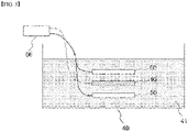
- FIG. 3 is a schematic diagram illustrating a pre-lithiation process according to another embodiment of the present invention.
- the pre-lithiating of the negative electrode 10 is performed by connecting the negative electrode 10 to a lithium metal 50 and performing electrochemical charge.
- the pre-lithiation is performed in a pre-lithiation reactor 40 which accommodates a pre-lithiation solution 41.
- the pre-lithiation reactor 40 where the pre-lithiation solution 41 has been accommodated, accommodates the negative electrode 10 in a state that is spaced apart from the lithium metal 50, and electrochemical charge can be performed after connecting the negative electrode 10 and the lithium metal 50 to the charge-discharge device 60, respectively.
- the lithium metal 50 may have a sheet form disposed to face the negative electrode 10.
- the lithium metal 50 can prevent a short circuit phenomenon which may occur by a direct contact between the negative electrode 10 and the lithium metal 50 during electrochemical charge by being spaced apart from the negative electrode 10.
- the step of impregnating the negative electrode 10 in the pre-lithiation solution 41 may be performed before performing electrochemical charge.
- the pre-lithiation solution 41 may contain a lithium salt and an organic solvent.
- the lithium salt may contain at least one selected from the group consisting of LiCl, LiBr, LiI, LiClO 4 , LiBF 4 , LiB 10 Cl 10 , LiPF 6 , LiCF 3 SO 3 , LiCF 3 CO 2 , LiAsF 6 , LiSbF 6 , LiAlCl 4 , CH 3 SO 3 Li, CF 3 SO 3 Li, (CF 3 SO 2 ) 2 NLi, (FSO 2 ) 2 NLi, chloro boran lithium, low aliphatic carboxylic acid lithium, and 4 phenyl boric acid lithium.
- the organic solvent may contain at least one selected from the group consisting of a carbonate solvent and an ester-based solvent.
- the non-aqueous solvent may contain at least one selected from the group consisting of propylene carbonate (PC), ethylene carbonate (EC), diethyl carbonate (DEC), dimethylcarbonate (DMC), diprophykane (DPC), dimethylsulfoxide, acetonitrile, dimethoxyethane, diethoxyethane, tetrahydrofuran, N-methyl-2-pyrrolidone (NMP), ethyl methylcarbonate (EMC), gamma boutirolactone (g-boutilactone), ethyl propionate, methyl bropopone, but the present invention is not limited thereto.
- PC propylene carbonate
- EC ethylene carbonate
- DEC diethyl carbonate
- DMC dimethylcarbonate
- DPC diprophykane
- dimethylsulfoxide acetonitrile,
- lithium ions which are intercalated by pre-lithiation, may be uniformly diffused to the surface and inside of the negative electrode active material layer.
- an inorganic coating layer is formed on the surface of the negative electrode by aging the pre-lithiated negative electrode under a CO 2 atmosphere. Specifically, an inorganic coating layer is formed by reaction between lithium ions and CO 2 in the negative electrode active material layer in the process of aging the negative electrode under a CO 2 atmosphere.
- the inorganic coating layer includes one or more compounds selected from the group consisting of Li 2 O, LiOH and Li 2 CO 3 , and specifically, the inorganic coating layer may include all of Li 2 O, LiOH and Li 2 CO 3 .
- the compounds have an excellent ability in blocking electron transport. As such, when an inorganic coating layer including such a compound is formed, it is possible to effectively block the redox reaction between air or moisture in the air and lithium ions introduced to the negative electrode active material layer.
- the aging may be carried out in a vacuum-based environment, and for example, the pre-lithiated negative electrode can be stored in a sealed chamber and then the aging can be performed in a CO 2 atmosphere.
- aging is performed under a CO 2 atmosphere and may be performed in a state that has lowered the pressure of CO 2 to be close to a vacuum state.
- a pressure of CO 2 during the aging may be in a range of 0.1 to 10 mTorr.
- the pressure of CO 2 during the aging may be in a range of 1 to 5 mTorr. It is possible to form an inorganic coating layer having a suitable thickness in the pressure range.
- the aging temperature may be in the range of 20 to 60°C, and specifically in the range of 30 to 50°C. In the above temperature range, the lithium ions in the negative electrode can be reacted with CO 2 at an appropriate speed.
- the aging time may be in the range of 10 to 60 hours, and specifically in the range of 20 to 50 hours.
- an appropriate amount of lithium ions can react with CO 2 to thereby form an inorganic coating layer.
- the reaction of lithium ions and CO 2 may not be smooth, and when the aging time exceeds the above range, the amount of lithium ions reacted with CO 2 may become too large.
- an inorganic coating layer capable of blocking a redox reaction on the surface of the negative electrode by aging the pre-lithiated negative electrode under a CO 2 atmosphere.
- the present invention provides a negative electrode.
- the negative electrode has a negative electrode active material layer formed thereon by coating a negative electrode slurry including a negative electrode active material.
- the negative electrode active material layer is pre-lithiated, and one or more compounds selected from the group consisting of Li 2 O, LiOH and Li 2 CO 3 are included in the surface of the negative electrode active material layer.
- the negative electrode may be manufactured by a method of manufacturing the above-described negative electrode.
- An inorganic coating layer capable of blocking the oxidation-reduction reaction is formed on the surface of the negative electrode according to the present invention. As such, it is possible to suppress the loss of lithium caused by redox reaction between the negative electrode and air and the moisture in the air, and it is possible to prevent the decrease of cycle characteristics and capacity of a battery.
- the present invention provides a method of manufacturing a secondary battery including the negative electrode described above.
- the secondary battery has a form where an electrode assembly, which has a form that a separator is interposed between a positive electrode and a negative electrode, is accommodated in a battery case.
- the positive electrode has a structure that a positive electrode active material layer is formed as a positive electrode slurry containing a positive electrode active material is applied on a positive electrode current collector.
- the negative electrode the above-described one may be used as the negative electrode, and the negative electrode may be manufactured by the method of manufacturing a negative electrode according to the present invention.
- the positive electrode collector generally has a thickness of 3 to 500 micrometers.
- the positive electrode current collector is not particularly limited as long as it has high conductivity without causing a chemical change in the battery.
- Examples of the positive electrode current collector include stainless steel, aluminum, nickel, titanium, sintered carbon or aluminum or stainless steel of which the surface has been treated with carbon, nickel, titanium, silver, or the like.
- the current collector may have fine irregularities on the surface thereof to increase the adhesion of the positive electrode active material, and various forms such as a film, a sheet, a foil, a net, a porous body, a foam, and a nonwoven fabric are possible.
- the positive electrode active material is a material capable of causing an electrochemical reaction and a lithium transition metal oxide, and contains two or more transition metals.
- the positive electrode slurry further contains a conductive material and a binder as well as a positive electrode active material, which is as described above.
- the separator is interposed between the positive electrode and the negative electrode, and an insulating thin film having high ion permeability and mechanical strength is used.
- the pore diameter of the separator is generally 0.01 to 10 micrometers, and the thickness is generally 5 to 300 micrometers.
- Examples of such a separator include olefin-based polymers such as polypropylene which is chemically resistant and hydrophobic; a sheet or a nonwoven fabric made of glass fiber, polyethylene or the like.
- the solid electrolyte such as a polymer
- the solid electrolyte may also serve as a separator.
- the battery case is not particularly limited as long as it is used as an exterior material for packaging the battery, and a cylindrical, square, or pouch type may be used and specifically a pouch-type battery case may be used.
- the pouch-type battery case is generally made of an aluminum laminate sheet and may be composed of an inner sealant layer for sealing, a metal layer for preventing permeation of materials, and an external resin layer forming the outermost part of the case. Details of the battery case are known to those of ordinary skill in the art, and thus detailed description thereof will be omitted.
- the electrolyte solution When an electrode assembly is accommodated in a battery case, the electrolyte solution is injected and sealed. Thereafter, a final secondary battery is manufactured through the formation process.
- a lithium salt and an organic solvent used in the above-described pre-lithiation solution may be used as the electrolyte solution. Details about the electrolyte solution are known to those of ordinary skill in the art, and thus detailed description thereof will be omitted.
- a mixture of 85 wt% of graphite and 15 wt% of SiO was prepared as the negative electrode active material. 94.5wt% of the negative electrode active material, 1.3wt% of Denka black as the conductive material, 3.0wt% of SBR as the binder, and 1.2wt% of CMC as the thickener were added to water to thereby prepare a negative electrode slurry.
- a negative electrode was manufactured by forming a negative electrode active material layer on two surfaces of a copper negative electrode current collector by coating the negative electrode slurry on two surfaces of a copper current collector (thickness: 8 ⁇ m, loading amount: 6.48mAh/cm') and rolling and drying the slurry-coated current collector at a vacuum oven of 130°C.
- a lithium metal film having a thickness of 6 ⁇ m was laminated on the negative electrode active material layer of the negative electrode, which was then stored for a predetermined time, to thereby be pre-lithiated.
- An inorganic coating layer was formed on the surface by aging the pre-lithiated negative electrode in a chamber of a CO 2 atmosphere of 1 mTorr for 20 hours. At this time, the temperature inside the chamber was maintained at 50°C.
- a pre-lithiated negative electrode was prepared in the same manner as in Example 1 except that the aging process was not performed.
- a negative electrode was prepared in the same manner as in Example 1 except that the pre-lithiation and aging processes were not performed.
- a lithium secondary battery was manufactured by interposing a polypropylene separator between the negative electrode according to the example 1 and the comparative example 1, and the lithium metal counter electrode, and injecting an electrolyte. What was obtained by adding LiPF 6 as lithium salt and 2 wt% of fluoroethylene carbonate (FEC) as an additive, based on the total weight of the pre-lithiation solution, to an organic solvent, obtained by mixing ethyl methyl carbonate (EC) and ethyl methyl carbonate (EMC) in a volume ratio of 30:70, was used as the electrolyte.
- FEC fluoroethylene carbonate
- Each of the half cells was full-charged with constant current (CC) of 0.1C, which was then left alone for 20 minutes and was then discharged with the constant current (CC) of 0.1C until reaching 3.0 V.
- the discharge profile was obtained from this and the discharge capacity (capacity 1) was calculated.
- the negative electrode before the pre-lithiation step was manufactured as a half cell (reference cell), and the reference cell was charged and discharged as the above, to thereby calculate the discharge capacity (capacity 2).
- the lithium dosage was calculated from the difference between the capacity 1 and the capacity 2.
- Lithium dosage % capacity 1 ⁇ capacity 2 * 100 / capacity 2
- the lithium dosage was measured using the above method at a point of time right after starting storage and points of time after one day, 5 days and 12 days from the start of the storage. The result was shown in FIG. 4 .
- the lithium dosage of the negative electrode according to the example 1 was the same as the lithium dosage of the negative electrode according to the comparative example 1 at the point of time right after the start of the storage of the negative electrode, but as the storage time increases, the lithium dosage of the negative electrode according to the comparative example 1 decreased, compared to the lithium dosage of the negative electrode according to the example 1. This was because the lithium ions introduced into the negative electrode reacted with air and moisture in the air because an inorganic coating layer was not formed in the case of the negative electrode according to the comparative example 1. On the other hand, in the case of the negative electrode according to the example 1, an inorganic coating layer including Li 2 O, LiOH and Li 2 CO 3 is formed. As such, the reaction between lithium ions introduced into the negative electrode and air and the moisture in the air was suppressed as much as possible.
- a positive electrode was manufactured by coating a positive electrode slurry, which is generated by mixing LiNi 0.8 Co 0.1 Mn 0.1 O 2 as the positive electrode active material, super C as the conductive material, and PVdF as the binder at the weight ratio of 97: 1.5: 1.5, on an aluminum current collector, rolling the slurry-coated current collector and drying the current collector at 130°C.
- a lithium secondary battery was manufactured by interposing a polypropylene separator between the negative electrode according to the example 1 and the positive electrode and injecting an electrolyte. What was obtained by adding LiPF 6 as lithium salt and 2 wt% of fluoroethylene carbonate (FEC) as an additive, based on the total weight of the pre-lithiation solution, to an organic solvent, obtained by mixing ethyl methyl carbonate (EC) and ethyl methyl carbonate (EMC) in a volume ratio of 30:70, was used as the electrolyte.
- FEC fluoroethylene carbonate
- a lithium secondary battery was prepared in the same manner as in Example 2 using the negative electrode according to the Comparative Example 1.
- a lithium secondary battery was prepared in the same manner as in Example 2 using the negative electrode according to the Comparative Example 2.
- the capacity retention rates of the lithium secondary battery according to the examples and comparative examples were evaluated using an electrochemical charge-discharge device.
- the battery was charged at a current density of 0.1 C-rate up to a voltage of 4.2 V, and discharged to a voltage of 2.5 V at the same current density during discharging.
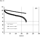
- the charging and discharging was carried out up to the 200-th cycle at the above condition.
- Capacity retention rate % discharge capacity in N-th cycle / discharge capacity in the first cycle ⁇ 100
- n is an integer between 1 to 200
- the lithium secondary battery according to Example 2 is excellent in capacity retention rate than lithium secondary battery according to Comparative Example 3 and Comparative Example 4. It was because, in the case of the secondary battery according to the example 2, an inorganic coating layer including Li 2 O, LiOH and Li 2 CO 3 is formed on the used negative electrode, and accordingly, the reaction between lithium ions introduced into the negative electrode and air and the moisture in the air was suppressed as much as possible. As a result, it was possible to maximize the amount of lithium ions stored in the negative electrode, and accordingly, the utilization of the capacity of the positive electrode could be maximized.
Landscapes
- Chemical & Material Sciences (AREA)
- General Chemical & Material Sciences (AREA)
- Chemical Kinetics & Catalysis (AREA)
- Electrochemistry (AREA)
- Engineering & Computer Science (AREA)
- Manufacturing & Machinery (AREA)
- Materials Engineering (AREA)
- Composite Materials (AREA)
- Inorganic Chemistry (AREA)
- Battery Electrode And Active Subsutance (AREA)
- Secondary Cells (AREA)
Abstract
Description
- This application claims the benefit of priority based on
Korean Patent Application No. 10-2020-0134992, filed on October 19, 2020 - The present invention relates to a method of manufacturing a negative electrode, and a negative electrode manufactured by the method of manufacturing a negative electrode, and more specifically, to a method of manufacturing a negative electrode having an inorganic coating layer formed thereon, and a negative electrode manufactured by the method.
- Recently, secondary batteries capable of charging and discharging have been widely used as energy sources of wireless mobile devices. In addition, the secondary battery has attracted attention as an energy source of an electric vehicle, a hybrid electric vehicle, etc., which are proposed as a solution for air pollution of existing gasoline vehicles and diesel vehicles using fossil fuel. Therefore, the types of applications using the secondary battery are currently much diversified due to the advantages of the secondary battery, and it is expected that the secondary battery will be applied to many fields and products in the future.
- Such secondary batteries may be classified into lithium ion batteries, lithium ion polymer batteries, lithium polymer batteries, etc., depending on the composition of the electrode and the electrolyte, and among them, the amount of use of lithium-ion polymer batteries that are less likely to leak electrolyte and are easy to manufacture is on the increase. In general, secondary batteries are classified into cylindrical batteries and prismatic batteries in which an electrode assembly is embedded in a cylindrical or rectangular metal can, depending on the shape of a battery case, and pouch-type batteries in which the electrode assembly is embedded in a pouch-type case of an aluminum laminate sheet. The electrode assembly built into the battery case is composed of a positive electrode, a negative electrode, and a separator interposed between the positive electrode and the negative electrode, and is a power generating element capable of charging and discharging. The electrode assembly is classified into a jelly-roll type wound with a separator interposed between the positive electrode and the negative electrode which are long sheet-shaped and are coated with active materials, and a stack type in which a plurality of positive electrodes and negative electrodes of a predetermined size are sequentially stacked while a separator is interposed therebetween.
- The positive electrode and the negative electrode are formed by applying a positive electrode slurry containing a positive electrode active material and a negative electrode slurry containing a negative electrode active material to a positive electrode current collector and a negative electrode current collector, to thereby form a positive electrode active material layer and a negative electrode active material layer, respectively, followed by drying and rolling them.
- In the case of such a negative electrode, a passive film such as a solid electrolyte interface (SEI) layer is formed on the surface of the negative electrode during the initial charge. The passive film interrupts injection of the organic solvent into the negative electrode and suppresses decomposition reaction of the organic solvent, thereby stabilizing the structure of the negative electrode, improving the reversibility of the negative electrode, and allowing the negative electrode to be usable. However, since the formation reaction of the passive film is an irreversible reaction, the consumption of the lithium ions is caused, thereby decreasing the capacity of the battery, and as the battery cycle is repeated, the lithium ions are consumed, thereby causing capacity reduction and cycle lifespan reduction.
- As such, a method for forming a passive film on the surface of a negative electrode, preventing the capacity reduction and improving cycle lifespan by pre-lithiating the negative electrode through inserting lithium into the negative electrode is currently developed. Such a pre-lithiation method includes a physical method of allowing lithium metal to directly contact the surface of the negative electrode, and a method of connecting lithium metal with the negative electrode and electrochemically charging the negative electrode.
- However, since the pre-lithiated negative electrode is in a reduced state, by-products are generated by reaction between lithium ions and air or moisture in the air. Lithium, which is introduced in the pre-lithiation process, is lost due to generation of by-products, and the targeted lithium dosage decreases.
- The present invention is believed to solve at least some of the above problems. For example, an aspect of the present invention provides a method of manufacturing a negative electrode capable of suppressing the loss of lithium caused by redox reaction between the negative electrode and air and the moisture in the air, and a negative electrode manufactured by the method.
- A method of manufacturing a negative electrode according to the present invention includes: manufacturing a negative electrode having a negative electrode active material layer formed thereon by coating a negative electrode slurry including a negative electrode active material at least on one surface of a current collector; pre-lithiating the negative electrode; and forming an inorganic coating layer on a surface of the negative electrode active material layer by aging the pre-lithiated negative electrode under an CO2 atmosphere.
- At this time, the inorganic coating layer includes one or more compounds selected from the group consisting of Li2O, LiOH and Li2CO3.
- In a specific example, the inorganic coating layer may include all of Li2O, LiOH and Li2CO3.
- The negative electrode active material may be one or more selected from the group consisting of a graphite-based active material and a silicon-based active material.
- In one example, the pre-lithiating of the negative electrode may be performed by directly contacting a lithium metal on the negative electrode active material layer.
- At this time, the pre-lithiating of the negative electrode may include bonding a lithium metal film on the negative electrode active material layer and then performing lamination.
- In another example, the pre-lithiating of the negative electrode may be performed by connecting the negative electrode to a lithium metal and performing electrochemical charge.
- Further, in a specific example, a pressure of CO2 during the aging of the pre-lithiated negative electrode may be in a range of 0.1 to 10 mTorr.
- Further, in a specific example, an aging temperature may be in a range of 20 to 60°C.
- Further, in a specific example, aging time may be in a range of 10 to 60 hours.
- Further, the present invention provides a negative electrode. The negative electrode has a negative electrode active material layer formed thereon by coating a negative electrode slurry including a negative electrode active material. Herein, the negative electrode active material layer is pre-lithiated, and an inorganic coating layer, which includes one or more compounds selected from the group consisting of Li2O, LiOH and Li2CO3, may be formed on a surface of the negative electrode active material layer.
- Further, the present invention provides a secondary battery including the above-described negative electrode.
- According to the present invention, it is possible to form an inorganic coating layer capable of blocking a redox reaction on the surface of the negative electrode by aging the pre-lithiated negative electrode under a CO2 atmosphere. As such, it is possible to suppress the loss of lithium caused by redox reaction between the negative electrode and air and the moisture in the air, and it is possible to prevent the decrease of cycle characteristics and capacity of a battery.
-
-
FIG. 1 is a flowchart illustrating the sequence of a method of manufacturing a negative electrode according to the present invention. -
FIG. 2 is a schematic diagram illustrating a pre-lithiation process according to an embodiment of the present invention. -
FIG. 3 is a schematic diagram illustrating a pre-lithiation process according to another embodiment of the present invention. -
FIG. 4 is a graph showing a change in a lithium dosage according to the storage time for the negative electrode according to Example 1 and Comparative Example 1 of the present invention. -
FIG. 5 is a graph showing the capacity retention rate of the secondary battery according to Example 2 and Comparative Examples 3 and 4 of the present invention. - Hereinafter, the present invention will be described in detail with reference to the drawings. The terms and words used in the present specification and claims should not be construed as limited to ordinary or dictionary terms and the inventor may properly define the concept of the terms in order to best describe its invention. The terms and words should be construed as meaning and concept consistent with the technical idea of the present invention.
- In this application, it should be understood that terms such as "include" or "have" are intended to indicate that there is a feature, number, step, operation, component, part, or a combination thereof described on the specification, and they do not exclude in advance the possibility of the presence or addition of one or more other features or numbers, steps, operations, components, parts or combinations thereof. Also, when a portion such as a layer, a film, an area, a plate, etc. is referred to as being "on" another portion, this includes not only the case where the portion is "directly on" the another portion but also the case where further another portion is interposed therebetween. On the other hand, when a portion such as a layer, a film, an area, a plate, etc. is referred to as being "under" another portion, this includes not only the case where the portion is "directly under" the another portion but also the case where further another portion is interposed therebetween. In addition, to be disposed "on" in the present application may include the case disposed at the bottom as well as the top.
- Hereinafter, the present invention will be described in detail with reference to the drawings.
-
FIG. 1 is a flowchart illustrating the sequence of a method of manufacturing a negative electrode according to the present invention. - Referring to
FIG. 1 , a method of manufacturing a negative electrode according to the present invention includes: manufacturing a negative electrode having a negative electrode active material layer formed thereon by coating a negative electrode slurry including a negative electrode active material on the surface of a current collector (S10); pre-lithiating the negative electrode (S20); and forming an inorganic coating layer on a surface of the negative electrode active material layer by aging the pre-lithiated negative electrode under an CO2 atmosphere (S30). - As described above, since the pre-lithiated negative electrode is in a reduced state, by-products are generated by reaction between lithium ions and air or moisture in the air. Lithium, which is introduced in the pre-lithiation process, is lost due to generation of by-products, and the targeted lithium dosage decreases.
- According to the present invention, it is possible to form an inorganic coating layer capable of blocking a redox reaction on the surface of the negative electrode by aging the pre-lithiated negative electrode under a CO2 atmosphere. As such, it is possible to suppress the loss of lithium caused by redox reaction between the negative electrode and air and the moisture in the air, and it is possible to prevent the decrease of cycle characteristics and capacity of a battery.
- Hereinafter, each step of a method of manufacturing a negative electrode according to the present invention will be described in detail.
- First, in order to perform pre-lithiation, a negative electrode, which is a subject of pre-lithiation, is manufactured.
- The negative electrode may be manufactured by forming a negative electrode active material layer by coating a negative electrode slurry containing a negative electrode active material on at least one surface of the negative electrode current collector. The negative electrode slurry may further include conductive materials and binders.
- The negative electrode collector generally has a thickness of 3 to 500 micrometers. The negative electrode current collector is not particularly limited as long as it has electrical conductivity without causing chemical changes in the battery, and examples thereof include copper, stainless steel, aluminum, nickel, titanium, sintered carbon, copper or stainless steel of which the surface has been treated with carbon, nickel, titanium, silver or the like, aluminum-cadmium alloy, or the like. In addition, like the positive electrode current collector, fine unevenness can be formed on the surface to enhance the bonding force of the negative electrode active material, and it can be used in various forms such as a film, a sheet, a foil, a net, a porous body, a foam, and a nonwoven fabric.
- The negative electrode active material may contain at least one selected from the group consisting of a carbon-based active material and a silicon-based active material.
- The silicon-based active material may impart excellent capacity characteristics to the negative electrode or secondary battery of the present invention and may contain a compound represented by SiOx(0≤x<2). Since SiO2 does not react with lithium ions, lithium cannot be stored, and thus x is preferably in the above range. More preferably, the silicon-based oxide may be SiO. The average particle diameter (D50) of the silicon-based oxide may be 1 to 30 µm, and preferably 3 to 15 µm in terms of reducing side reaction with the electrolyte solution while maintaining structural stability during charge/discharge. The average particle diameter D50 may be measured using, for example, a laser diffraction method.
- The carbon-based active material may impart excellent cycle characteristics or battery lifespan performance to a secondary battery or a negative electrode for a secondary battery of the present invention. Specifically, the carbon-based active material may contain at least one selected from the group consisting of artificial graphite, natural graphite, hard carbon, soft carbon, carbon black, acetylene black, Ketjen black, super P, graphene and textile carbon, and preferably at least one selected from the group consisting of artificial graphite and natural graphite. The average particle diameter (D50) of the carbon-based oxide may be 10 to 30 µm, and preferably 15 to 25 µm in terms of reducing side reaction with the electrolyte solution while maintaining structural stability during charge/discharge.
- Specifically, both the silicon-based active material and the carbon-based active material may be used as the negative electrode active material in terms of improving both the capacity characteristics and cycle characteristics. Specifically, the negative electrode active material may include the carbon-based active material and the silicon-based active material in the weight ratio of 50: 50 to 95: 5, and preferably in the weight ratio of 60: 40 to 80: 20.
- The conductive material is usually added in an amount of 1 to 30% by weight based on the total weight of the mixture including the positive electrode active material. Such a conductive material is not particularly limited as long as it has electrical conductivity without causing a chemical change in the battery, and examples thereof include graphite such as natural graphite and artificial graphite; carbon black such as carbon black, acetylene black, Ketjen black, channel black, furnace black, lamp black, and summer black; conductive fibers such as carbon fiber and metal fiber; metal powders such as carbon fluoride, aluminum and nickel powder; conductive whiskey such as zinc oxide and potassium titanate; conductive metal oxides such as titanium oxide; and conductive materials such as polyphenylene derivatives and the like.
- The binder is added in an amount of 1 to 30% by weight, on the basis of the total weight of the mixture containing the positive electrode active material, as a component that assists in bonding between the active material and the conductive material and bonding to the current collector. Examples of such binders include polyvinylidene fluoride, polyvinyl alcohol, carboxymethylcellulose (CMC), starch, hydroxypropylcellulose, regenerated cellulose, polyvinylpyrrolidone, tetrafluoroethylene, polyethylene, polypropylene, ethylene-propylene-diene terpolymer (EPDM), sulfonated EPDM, styrene butylene rubber, fluorine rubber, various copolymers and the like.
- When a negative electrode is manufactured, the negative electrode is pre-lithiated.
- In the present invention, there is no particular limitation on the method of pre-lithiating the negative electrode, and for example, both physicochemical methods or electrochemical methods can be used.
- In one example, the pre-lithiating of the negative electrode is performed by directly contacting a lithium metal on the negative electrode active material layer.
-
FIG. 2 is a schematic diagram illustrating a pre-lithiation process according to an embodiment of the present invention. - Referring to
FIG. 2 , the pre-lithiating of thenegative electrode 10 includes bonding alithium metal film 20 on the negative electrodeactive material layer 12 and then performing lamination. - Specifically, when the
negative electrode 10 is prepared, thelithium metal film 20 is laminated. This process can be performed, for example, by a roll-to-roll process. In this case, the negative electrode is wound by an unwinding roller (not shown) and is then unwound when the lamination is started. Further, alithium metal film 20 is also wound on a separate roll (not shown) and is then unwound when the lamination is started. At this time, thelithium metal film 20 itself may be used, but what is obtained by laminating a lithium metal film on one surface of a polymer film (not shown) may also be used. The thickness of thelithium metal film 20 may be in the range of 1 to 10 µm, and specifically in the range of 3 to 8 µm. When the thickness of thelithium metal film 20 is in the above range, an appropriate amount of lithium ions may be doped on the negative electrode. - Thereafter, the
lithium metal film 20 is bonded to a negative electrodeactive material layer 12 formed on the negative electrodecurrent collector 11. Thereafter, thelithium metal film 20 and thenegative electrode 10 are pressed using the pressingmember 30. The shape of the pressingmember 30 is not particularly limited. However, as shown inFIG. 2 , it is possible to use a pair of pressing rollers, or it is possible to apply surface pressure to thelithium metal film 20 and thenegative electrode 10 by using the pressing jig of a rectangular shape. However, when using a pair of pressing rollers, nip pressure is applied to thenegative electrode 10 and thelithium metal film 20, and accordingly, uniform force can be applied. As such, the lower pressure can be applied, compared to the case of applying surface pressure. - As the
negative electrode 10, on which thelithium metal film 20 has been laminated, is stored for a predetermined time, lithium ions, which are intercalated by pre-lithiation, may be uniformly diffused to the surface and inside of the negative electrodeactive material layer 12. -
FIG. 3 is a schematic diagram illustrating a pre-lithiation process according to another embodiment of the present invention. - Referring to
FIG. 3 , the pre-lithiating of thenegative electrode 10 is performed by connecting thenegative electrode 10 to alithium metal 50 and performing electrochemical charge. - In this case, the pre-lithiation is performed in a
pre-lithiation reactor 40 which accommodates apre-lithiation solution 41. Specifically, thepre-lithiation reactor 40, where thepre-lithiation solution 41 has been accommodated, accommodates thenegative electrode 10 in a state that is spaced apart from thelithium metal 50, and electrochemical charge can be performed after connecting thenegative electrode 10 and thelithium metal 50 to the charge-discharge device 60, respectively. Thelithium metal 50 may have a sheet form disposed to face thenegative electrode 10. Thelithium metal 50 can prevent a short circuit phenomenon which may occur by a direct contact between thenegative electrode 10 and thelithium metal 50 during electrochemical charge by being spaced apart from thenegative electrode 10. Further, the step of impregnating thenegative electrode 10 in thepre-lithiation solution 41 may be performed before performing electrochemical charge. - The
pre-lithiation solution 41 may contain a lithium salt and an organic solvent. - Specifically, the lithium salt may contain at least one selected from the group consisting of LiCl, LiBr, LiI, LiClO4, LiBF4, LiB10Cl10, LiPF6, LiCF3SO3, LiCF3CO2, LiAsF6, LiSbF6, LiAlCl4, CH3SO3Li, CF3SO3Li, (CF3SO2)2NLi, (FSO2)2NLi, chloro boran lithium, low aliphatic carboxylic acid lithium, and 4 phenyl boric acid lithium.
- For example, the organic solvent may contain at least one selected from the group consisting of a carbonate solvent and an ester-based solvent. The non-aqueous solvent may contain at least one selected from the group consisting of propylene carbonate (PC), ethylene carbonate (EC), diethyl carbonate (DEC), dimethylcarbonate (DMC), diprophykane (DPC), dimethylsulfoxide, acetonitrile, dimethoxyethane, diethoxyethane, tetrahydrofuran, N-methyl-2-pyrrolidone (NMP), ethyl methylcarbonate (EMC), gamma boutirolactone (g-boutilactone), ethyl propionate, methyl bropopone, but the present invention is not limited thereto.
- Likewise, as the electrochemically charged
negative electrode 10 is stored for a predetermined time after washing and drying, lithium ions, which are intercalated by pre-lithiation, may be uniformly diffused to the surface and inside of the negative electrode active material layer. - When pre-lithiation is completed, an inorganic coating layer is formed on the surface of the negative electrode by aging the pre-lithiated negative electrode under a CO2 atmosphere. Specifically, an inorganic coating layer is formed by reaction between lithium ions and CO2 in the negative electrode active material layer in the process of aging the negative electrode under a CO2 atmosphere.
- At this time, the inorganic coating layer includes one or more compounds selected from the group consisting of Li2O, LiOH and Li2CO3, and specifically, the inorganic coating layer may include all of Li2O, LiOH and Li2CO3. The compounds have an excellent ability in blocking electron transport. As such, when an inorganic coating layer including such a compound is formed, it is possible to effectively block the redox reaction between air or moisture in the air and lithium ions introduced to the negative electrode active material layer.
- Namely, it is possible to increase the amount of lithium ions which can be utilized as the lithium reservoir even if the same amount of lithium ions are introduced by suppressing the loss of the introduced lithium ions through pre-lithiation. As a result, it is possible to prevent the decrease of the capacity and cycle characteristics of the battery.
- Specifically, the aging may be carried out in a vacuum-based environment, and for example, the pre-lithiated negative electrode can be stored in a sealed chamber and then the aging can be performed in a CO2 atmosphere. Namely, aging is performed under a CO2 atmosphere and may be performed in a state that has lowered the pressure of CO2 to be close to a vacuum state. For example, a pressure of CO2 during the aging may be in a range of 0.1 to 10 mTorr. Specifically, the pressure of CO2 during the aging may be in a range of 1 to 5 mTorr. It is possible to form an inorganic coating layer having a suitable thickness in the pressure range. When the pressure of CO2 is less than the above range, the reaction between CO2 and lithium ions on the surface of the negative electrode may not be smooth, and when the pressure of CO2 exceeds the above range, the amount of lithium ions, which react with CO2, may become too large.
- Further, in the aging process, the aging temperature may be in the range of 20 to 60°C, and specifically in the range of 30 to 50°C. In the above temperature range, the lithium ions in the negative electrode can be reacted with CO2 at an appropriate speed.
- Further, in the aging process, the aging time may be in the range of 10 to 60 hours, and specifically in the range of 20 to 50 hours. When the aging time is within the above range, an appropriate amount of lithium ions can react with CO2 to thereby form an inorganic coating layer. When the aging time is less than the above range, the reaction of lithium ions and CO2 may not be smooth, and when the aging time exceeds the above range, the amount of lithium ions reacted with CO2 may become too large.
- Likewise, according to the present invention, it is possible to form an inorganic coating layer capable of blocking a redox reaction on the surface of the negative electrode by aging the pre-lithiated negative electrode under a CO2 atmosphere. As such, it is possible to suppress the loss of lithium caused by redox reaction between the negative electrode and air and the moisture in the air, and it is possible to prevent the decrease of cycle characteristics and capacity of a battery.
- Further, the present invention provides a negative electrode.
- The negative electrode has a negative electrode active material layer formed thereon by coating a negative electrode slurry including a negative electrode active material. Herein, the negative electrode active material layer is pre-lithiated, and one or more compounds selected from the group consisting of Li2O, LiOH and Li2CO3 are included in the surface of the negative electrode active material layer. At this time, the negative electrode may be manufactured by a method of manufacturing the above-described negative electrode.
- An inorganic coating layer capable of blocking the oxidation-reduction reaction is formed on the surface of the negative electrode according to the present invention. As such, it is possible to suppress the loss of lithium caused by redox reaction between the negative electrode and air and the moisture in the air, and it is possible to prevent the decrease of cycle characteristics and capacity of a battery.
- In addition, the present invention provides a method of manufacturing a secondary battery including the negative electrode described above.
- The secondary battery has a form where an electrode assembly, which has a form that a separator is interposed between a positive electrode and a negative electrode, is accommodated in a battery case. The positive electrode has a structure that a positive electrode active material layer is formed as a positive electrode slurry containing a positive electrode active material is applied on a positive electrode current collector. Further, with respect to the negative electrode, the above-described one may be used as the negative electrode, and the negative electrode may be manufactured by the method of manufacturing a negative electrode according to the present invention.
- In the present invention, the positive electrode collector generally has a thickness of 3 to 500 micrometers. The positive electrode current collector is not particularly limited as long as it has high conductivity without causing a chemical change in the battery. Examples of the positive electrode current collector include stainless steel, aluminum, nickel, titanium, sintered carbon or aluminum or stainless steel of which the surface has been treated with carbon, nickel, titanium, silver, or the like. The current collector may have fine irregularities on the surface thereof to increase the adhesion of the positive electrode active material, and various forms such as a film, a sheet, a foil, a net, a porous body, a foam, and a nonwoven fabric are possible.
- In the present invention, the positive electrode active material is a material capable of causing an electrochemical reaction and a lithium transition metal oxide, and contains two or more transition metals. Examples thereof include: layered compounds such as lithium cobalt oxide (LiCoO2) and lithium nickel oxide (LiNi02) substituted with one or more transition metals; lithium manganese oxide substituted with one or more transition metals; lithium nickel oxide represented by the formula LiNi1-yMyO2 (wherein M = Co, Mn, Al, Cu, Fe, Mg, B, Cr, Zn or Ga and contains at least one of the above elements, 0.01 ≦ y ≦ 0.7); lithium nickel cobalt manganese composite oxide represented by the formula Li1+zNibMncCo1-(b+c+d)MdO(2-e)Ae such as Li1+zNi1/3Co1/3Mn1/3O2, Li1+zNi0.4Mn0.4Co0.2O2 etc. (wherein - 0.5≤z≤0.5, 0.1≤b≤0.8, 0.1≤c≤0.8, 0≤d≤0.2, 0≤e≤0.2, b+c+d<1, M=Al, Mg, Cr, Ti, Si or Y, and A = F, P or Cl); olivine-based lithium metal phosphate represented by the formula Li1+xM1-yM'yPO4-zXz (wherein M = transition metal, preferably Fe, Mn, Co or Ni, M'= Al, Mg or Ti, X = F, S or N, and -0.5≤x≤0.5, 0≤y≤0.5, 0≤z≤0.1).
- Further, the positive electrode slurry further contains a conductive material and a binder as well as a positive electrode active material, which is as described above.
- The separator is interposed between the positive electrode and the negative electrode, and an insulating thin film having high ion permeability and mechanical strength is used. The pore diameter of the separator is generally 0.01 to 10 micrometers, and the thickness is generally 5 to 300 micrometers. Examples of such a separator include olefin-based polymers such as polypropylene which is chemically resistant and hydrophobic; a sheet or a nonwoven fabric made of glass fiber, polyethylene or the like. When a solid electrolyte such as a polymer is used as the electrolyte, the solid electrolyte may also serve as a separator.
- Further, the battery case is not particularly limited as long as it is used as an exterior material for packaging the battery, and a cylindrical, square, or pouch type may be used and specifically a pouch-type battery case may be used. The pouch-type battery case is generally made of an aluminum laminate sheet and may be composed of an inner sealant layer for sealing, a metal layer for preventing permeation of materials, and an external resin layer forming the outermost part of the case. Details of the battery case are known to those of ordinary skill in the art, and thus detailed description thereof will be omitted.
- When an electrode assembly is accommodated in a battery case, the electrolyte solution is injected and sealed. Thereafter, a final secondary battery is manufactured through the formation process. A lithium salt and an organic solvent used in the above-described pre-lithiation solution may be used as the electrolyte solution. Details about the electrolyte solution are known to those of ordinary skill in the art, and thus detailed description thereof will be omitted.
- Hereinafter, the present invention will be described in detail with reference to examples. However, the embodiments according to the present invention may be modified into various other forms, and the scope of the present invention should not be construed as being limited to the examples described below. The examples of the present invention are provided to more fully describe the present invention to those skilled in the art.
- A mixture of 85 wt% of graphite and 15 wt% of SiO was prepared as the negative electrode active material. 94.5wt% of the negative electrode active material, 1.3wt% of Denka black as the conductive material, 3.0wt% of SBR as the binder, and 1.2wt% of CMC as the thickener were added to water to thereby prepare a negative electrode slurry.
- A negative electrode was manufactured by forming a negative electrode active material layer on two surfaces of a copper negative electrode current collector by coating the negative electrode slurry on two surfaces of a copper current collector (thickness: 8 µm, loading amount: 6.48mAh/cm') and rolling and drying the slurry-coated current collector at a vacuum oven of 130°C.
- A lithium metal film having a thickness of 6 µm was laminated on the negative electrode active material layer of the negative electrode, which was then stored for a predetermined time, to thereby be pre-lithiated.
- An inorganic coating layer was formed on the surface by aging the pre-lithiated negative electrode in a chamber of a CO2 atmosphere of 1 mTorr for 20 hours. At this time, the temperature inside the chamber was maintained at 50°C.
- A pre-lithiated negative electrode was prepared in the same manner as in Example 1 except that the aging process was not performed.
- A negative electrode was prepared in the same manner as in Example 1 except that the pre-lithiation and aging processes were not performed.
- The negative electrode manufactured in the example 1 and the comparative example 1, and a lithium metal having a thickness of 150 µm, which corresponds to a counter electrode to the negative electrode, were prepared.
- A lithium secondary battery was manufactured by interposing a polypropylene separator between the negative electrode according to the example 1 and the comparative example 1, and the lithium metal counter electrode, and injecting an electrolyte. What was obtained by adding LiPF6 as lithium salt and 2 wt% of fluoroethylene carbonate (FEC) as an additive, based on the total weight of the pre-lithiation solution, to an organic solvent, obtained by mixing ethyl methyl carbonate (EC) and ethyl methyl carbonate (EMC) in a volume ratio of 30:70, was used as the electrolyte.
- Each of the half cells was full-charged with constant current (CC) of 0.1C, which was then left alone for 20 minutes and was then discharged with the constant current (CC) of 0.1C until reaching 3.0 V. The discharge profile was obtained from this and the discharge capacity (capacity 1) was calculated.
- Further, with respect to the negative electrode according to the example 1 and the comparative example 1, the negative electrode before the pre-lithiation step was manufactured as a half cell (reference cell), and the reference cell was charged and discharged as the above, to thereby calculate the discharge capacity (capacity 2). The lithium dosage was calculated from the difference between the
capacity 1 and thecapacity 2.
- As the negative electrode according to the example 1 and the comparative example 1 is stored in a dry room at a room temperature, the lithium dosage was measured using the above method at a point of time right after starting storage and points of time after one day, 5 days and 12 days from the start of the storage. The result was shown in
FIG. 4 . - Referring to
FIG. 4 , the lithium dosage of the negative electrode according to the example 1 was the same as the lithium dosage of the negative electrode according to the comparative example 1 at the point of time right after the start of the storage of the negative electrode, but as the storage time increases, the lithium dosage of the negative electrode according to the comparative example 1 decreased, compared to the lithium dosage of the negative electrode according to the example 1. This was because the lithium ions introduced into the negative electrode reacted with air and moisture in the air because an inorganic coating layer was not formed in the case of the negative electrode according to the comparative example 1. On the other hand, in the case of the negative electrode according to the example 1, an inorganic coating layer including Li2O, LiOH and Li2CO3 is formed. As such, the reaction between lithium ions introduced into the negative electrode and air and the moisture in the air was suppressed as much as possible. - A positive electrode was manufactured by coating a positive electrode slurry, which is generated by mixing LiNi0.8Co0.1Mn0.1O2 as the positive electrode active material, super C as the conductive material, and PVdF as the binder at the weight ratio of 97: 1.5: 1.5, on an aluminum current collector, rolling the slurry-coated current collector and drying the current collector at 130°C.
- A lithium secondary battery was manufactured by interposing a polypropylene separator between the negative electrode according to the example 1 and the positive electrode and injecting an electrolyte. What was obtained by adding LiPF6 as lithium salt and 2 wt% of fluoroethylene carbonate (FEC) as an additive, based on the total weight of the pre-lithiation solution, to an organic solvent, obtained by mixing ethyl methyl carbonate (EC) and ethyl methyl carbonate (EMC) in a volume ratio of 30:70, was used as the electrolyte.
- A lithium secondary battery was prepared in the same manner as in Example 2 using the negative electrode according to the Comparative Example 1.
- A lithium secondary battery was prepared in the same manner as in Example 2 using the negative electrode according to the Comparative Example 2.
- The capacity retention rates of the lithium secondary battery according to the examples and comparative examples were evaluated using an electrochemical charge-discharge device. During charging, the battery was charged at a current density of 0.1 C-rate up to a voltage of 4.2 V, and discharged to a voltage of 2.5 V at the same current density during discharging. The charging and discharging was carried out up to the 200-th cycle at the above condition.
- In this process, the capacity retention rate was evaluated according to the following
formula 2, and the results are shown inFIG. 5 . -

- Referring to
FIG. 5 , it can be seen that the lithium secondary battery according to Example 2 is excellent in capacity retention rate than lithium secondary battery according to Comparative Example 3 and Comparative Example 4. It was because, in the case of the secondary battery according to the example 2, an inorganic coating layer including Li2O, LiOH and Li2CO3 is formed on the used negative electrode, and accordingly, the reaction between lithium ions introduced into the negative electrode and air and the moisture in the air was suppressed as much as possible. As a result, it was possible to maximize the amount of lithium ions stored in the negative electrode, and accordingly, the utilization of the capacity of the positive electrode could be maximized. - The above description is merely illustrative of the technical idea of the present invention, and those skilled in the art to which the present invention pertains may make various modifications and variations without departing from the essential characteristics of the present invention. Therefore, the drawings disclosed in the present invention are not intended to limit the technical idea of the present invention but to describe the present invention, and the scope of the technical idea of the present invention is not limited by these drawings. The scope of protection of the present invention should be interpreted by the following claims, and all technical ideas within the scope equivalent thereto should be construed as being included in the scope of the present invention.
- On the other hand, in this specification, terms indicating directions such as up, down, left, right, before, and after are used, but it is obvious that these terms are for convenience of description only and may change depending on the location of the object or the location of the observer.
-
- 10: negative electrode
- 11: current collector
- 12: negative electrode active material layer
- 20: lithium metal film
- 30: pressing member
- 40: pre-lithiation reactor
- 41: pre-lithiation solution
- 50: lithium metal
- 60: charge-discharge device
Claims (12)
- A method of manufacturing a negative electrode, the method comprising:manufacturing a negative electrode having a negative electrode active material layer formed thereon by coating a negative electrode slurry including a negative electrode active material at least on one surface of a current collector;pre-lithiating the negative electrode; andforming an inorganic coating layer on a surface of the negative electrode active material layer by aging the pre-lithiated negative electrode under an CO2 atmosphere.
- The method of claim 1, wherein the inorganic coating layer includes one or more compounds selected from the group consisting of Li2O, LiOH and Li2CO3.
- The method of claim 1, wherein the inorganic coating layer includes all of Li2O, LiOH and Li2CO3.
- The method of claim 1, wherein the negative electrode active material is one or more selected from the group consisting of a graphite-based active material and a silicon-based active material.
- The method of claim 1, wherein the pre-lithiating of the negative electrode is performed by directly contacting a lithium metal on the negative electrode active material layer.
- The method of claim 5, wherein the pre-lithiating of the negative electrode includes bonding a lithium metal film on the negative electrode active material layer and then performing lamination.
- The method of claim 1, wherein the pre-lithiating of the negative electrode is performed by connecting the negative electrode to a lithium metal and performing electrochemical charge.
- The method of claim 1, wherein a pressure of CO2 during the aging of the pre-lithiated negative electrode is in a range of 0.1 to 10 mTorr.
- The method of claim 1, wherein an aging temperature is in a range of 20 to 60°C.
- The method of claim 1, wherein aging time is in a range of 10 to 60 hours.
- A negative electrode having a negative electrode active material layer formed thereon by coating a negative electrode slurry including a negative electrode active material,wherein the negative electrode active material layer is pre-lithiated, andwherein an inorganic coating layer, which includes one or more compounds selected from the group consisting of Li2O, LiOH and Li2CO3, is formed on a surface of the negative electrode active material layer.
- A secondary battery including the negative electrode according to claim 11.
Applications Claiming Priority (2)
| Application Number | Priority Date | Filing Date | Title |
|---|---|---|---|
| KR1020200134992A KR102966115B1 (en) | 2020-10-19 | Method for manufacturing negative electrode with inorganic coating layer | |
| PCT/KR2021/013711 WO2022085995A1 (en) | 2020-10-19 | 2021-10-06 | Method for manufacturing anode having inorganic coating layer formed thereon |
Publications (3)
| Publication Number | Publication Date |
|---|---|
| EP4117055A1 true EP4117055A1 (en) | 2023-01-11 |
| EP4117055A4 EP4117055A4 (en) | 2024-01-17 |
| EP4117055B1 EP4117055B1 (en) | 2025-11-26 |
Family
ID=81290734
Family Applications (1)
| Application Number | Title | Priority Date | Filing Date |
|---|---|---|---|
| EP21883067.7A Active EP4117055B1 (en) | 2020-10-19 | 2021-10-06 | Method of manufacturing negative electrode having inorganic coating layer formed thereon |
Country Status (6)
| Country | Link |
|---|---|
| US (1) | US12482815B2 (en) |
| EP (1) | EP4117055B1 (en) |
| JP (1) | JP7600261B2 (en) |
| CN (1) | CN115398673A (en) |
| ES (1) | ES3057717T3 (en) |
| WO (1) | WO2022085995A1 (en) |
Families Citing this family (1)
| Publication number | Priority date | Publication date | Assignee | Title |
|---|---|---|---|---|
| CN116487818A (en) * | 2023-04-28 | 2023-07-25 | 惠州亿纬锂能股份有限公司 | A kind of lithium battery SEI film stabilizing method and its application |
Family Cites Families (27)
| Publication number | Priority date | Publication date | Assignee | Title |
|---|---|---|---|---|
| DE4491020B4 (en) * | 1993-02-18 | 2005-12-01 | Fmc Corp. | Process for the preparation of alkali metal dispersions |
| US20090148773A1 (en) | 2007-12-06 | 2009-06-11 | Ener1, Inc. | Lithium-ion secondary battery cell, electrode for the battery cell, and method of making the same |
| JP2009164014A (en) | 2008-01-08 | 2009-07-23 | Mitsui Mining & Smelting Co Ltd | Anode for non-aqueous electrolyte secondary battery |
| JP2010073402A (en) | 2008-09-17 | 2010-04-02 | Panasonic Corp | Method for manufacturing negative electrode for lithium secondary battery |
| KR101128585B1 (en) | 2010-07-26 | 2012-03-23 | 삼성전기주식회사 | Pre-doping System of electrode and pre-doping method of electrode using the same |
| TWI473320B (en) | 2012-01-06 | 2015-02-11 | Univ Nat Taiwan Science Tech | Anode protector of lithium-ion battery and method for fabricating the same |
| CN102642024B (en) | 2012-03-06 | 2014-07-23 | 宁德新能源科技有限公司 | Lithium ion battery and anode strip thereof and stabilization lithium metal powder |
| JP6085994B2 (en) | 2012-04-27 | 2017-03-01 | 日産自動車株式会社 | Method for producing non-aqueous electrolyte secondary battery |
| CN104956522A (en) | 2013-01-30 | 2015-09-30 | 那诺思卡乐康母庞特公司 | Phased introduction of lithium into the pre-lithiated anode of a lithium ion electrochemical cell |
| BR112016018553B1 (en) | 2014-02-13 | 2021-07-06 | Rockwood Lithium GmbH | coated lithiated graphite powder manufacturing method, use of coated, flowable lithiated graphite powder, and lithium battery anode manufacturing method |
| EP4037007A1 (en) * | 2014-11-03 | 2022-08-03 | 24M Technologies, Inc. | Battery cell comprising a semi-solid electrode |
| CN104993104B (en) | 2015-05-19 | 2017-04-19 | 浙江大学 | Preparation method of multi-element polyphase composite lithium ion battery negative material |
| DE102015217809A1 (en) | 2015-09-17 | 2017-03-23 | Robert Bosch Gmbh | Prelithiated, carbon-coated anode active material |
| JP6962032B2 (en) | 2017-02-28 | 2021-11-05 | 株式会社豊田自動織機 | Method for manufacturing lithium negative electrode complex |
| KR20220132656A (en) | 2017-04-17 | 2022-09-30 | 로베르트 보쉬 게엠베하 | Pre-lithiated silicon-based anode, and manufacturing method thereof |
| KR102283684B1 (en) | 2017-07-31 | 2021-08-02 | 주식회사 엘지에너지솔루션 | Lithium deposited anode for Lithium Second Battery and Method for Preparation thereof |
| KR102327179B1 (en) | 2017-08-10 | 2021-11-16 | 주식회사 엘지에너지솔루션 | Pre-lithiation method of lithium secondary battery anode using lithium metal-ceramic thin layer |
| KR102261504B1 (en) | 2017-08-10 | 2021-06-07 | 주식회사 엘지에너지솔루션 | Pre-lithiation Method of Anode Electrodes for secondary battery |
| KR20190044450A (en) | 2017-10-20 | 2019-04-30 | 주식회사 엘지화학 | Lithium secondary battery with improved cycle life and ultra-high energy density |
| KR102601605B1 (en) * | 2017-12-27 | 2023-11-14 | 삼성전자주식회사 | Anode, Lithium battery comprising anode, and Preparation method of anode |
| KR102790285B1 (en) | 2018-01-03 | 2025-04-03 | 주식회사 엘지에너지솔루션 | A method of pre-lithiating anode and Anode manufactured therefrom |
| JPWO2019181703A1 (en) | 2018-03-23 | 2021-03-18 | 株式会社Adeka | How to suppress thermal runaway due to internal short circuit |
| KR102386321B1 (en) | 2018-04-03 | 2022-04-14 | 주식회사 엘지에너지솔루션 | Negative electrode for lithium secondary battery, preparing method thereof, and lithium secondary battery comprising the same |
| KR20200053300A (en) | 2018-11-08 | 2020-05-18 | 주식회사 포스코 | Negative electrode for lithium secondary battery, method of preparing the saem, and lithium secondary battery using the same |
| KR20200134992A (en) | 2019-05-24 | 2020-12-02 | 현대모비스 주식회사 | Electronic control unit for vehicle having one body structure |
| US11527745B2 (en) * | 2019-09-03 | 2022-12-13 | GM Global Technology Operations LLC | Methods of pre-lithiating electrodes |
| US11811051B2 (en) * | 2020-09-22 | 2023-11-07 | Apple Inc. | Electrochemical cell design with lithium metal anode |
-
2021
- 2021-10-06 WO PCT/KR2021/013711 patent/WO2022085995A1/en not_active Ceased
- 2021-10-06 EP EP21883067.7A patent/EP4117055B1/en active Active
- 2021-10-06 US US17/914,794 patent/US12482815B2/en active Active
- 2021-10-06 JP JP2022560126A patent/JP7600261B2/en active Active
- 2021-10-06 ES ES21883067T patent/ES3057717T3/en active Active
- 2021-10-06 CN CN202180028864.2A patent/CN115398673A/en active Pending
Also Published As
| Publication number | Publication date |
|---|---|
| EP4117055A4 (en) | 2024-01-17 |
| ES3057717T3 (en) | 2026-03-04 |
| JP2023521314A (en) | 2023-05-24 |
| EP4117055B1 (en) | 2025-11-26 |
| US20230135232A1 (en) | 2023-05-04 |
| CN115398673A (en) | 2022-11-25 |
| WO2022085995A1 (en) | 2022-04-28 |
| US12482815B2 (en) | 2025-11-25 |
| JP7600261B2 (en) | 2024-12-16 |
| KR20220051500A (en) | 2022-04-26 |
Similar Documents
| Publication | Publication Date | Title |
|---|---|---|
| EP3561918B1 (en) | Pre-lithiation method for anode for secondary battery | |
| US11876191B2 (en) | Method for activating secondary battery | |
| US11456446B2 (en) | Method for pre-lithiation of negative electrode for secondary battery | |
| EP3675266B1 (en) | Battery cell in which gelled electrolyte component is included in pore of separator configuring electrode assembly | |
| KR102886191B1 (en) | Negative electrode and method of pre-lithiating a negative electrode | |
| KR102542291B1 (en) | Method for manufacturing negative electrode for secondary battery | |
| EP4020627B1 (en) | Device for pre-lithiation of negative electrode and method for pre-lithiation of negative electrode | |
| EP2966120B1 (en) | Cross-linked compound particles and secondary battery comprising same | |
| EP4037021B1 (en) | A method of pre-lithiating a negative electrode | |
| KR102900648B1 (en) | Method for pre-lithiating the negative electrode | |
| EP4117055B1 (en) | Method of manufacturing negative electrode having inorganic coating layer formed thereon | |
| US12334535B2 (en) | Apparatus for pre-lithiation of negative electrode and method for pre-lithiation of negative electrode | |
| KR102966115B1 (en) | Method for manufacturing negative electrode with inorganic coating layer |
Legal Events
| Date | Code | Title | Description |
|---|---|---|---|
| STAA | Information on the status of an ep patent application or granted ep patent |
Free format text: STATUS: THE INTERNATIONAL PUBLICATION HAS BEEN MADE |
|
| PUAI | Public reference made under article 153(3) epc to a published international application that has entered the european phase |
Free format text: ORIGINAL CODE: 0009012 |
|
| STAA | Information on the status of an ep patent application or granted ep patent |
Free format text: STATUS: REQUEST FOR EXAMINATION WAS MADE |
|
| 17P | Request for examination filed |
Effective date: 20221005 |
|
| AK | Designated contracting states |
Kind code of ref document: A1 Designated state(s): AL AT BE BG CH CY CZ DE DK EE ES FI FR GB GR HR HU IE IS IT LI LT LU LV MC MK MT NL NO PL PT RO RS SE SI SK SM TR |
|
| A4 | Supplementary search report drawn up and despatched |
Effective date: 20231215 |
|
| RIC1 | Information provided on ipc code assigned before grant |
Ipc: H01M 10/052 20100101ALI20231211BHEP Ipc: H01M 4/62 20060101ALI20231211BHEP Ipc: H01M 4/13 20100101ALI20231211BHEP Ipc: H01M 4/04 20060101ALI20231211BHEP Ipc: H01M 4/139 20100101AFI20231211BHEP |
|
| DAV | Request for validation of the european patent (deleted) | ||
| DAX | Request for extension of the european patent (deleted) | ||
| GRAP | Despatch of communication of intention to grant a patent |
Free format text: ORIGINAL CODE: EPIDOSNIGR1 |
|
| STAA | Information on the status of an ep patent application or granted ep patent |
Free format text: STATUS: GRANT OF PATENT IS INTENDED |
|
| INTG | Intention to grant announced |
Effective date: 20250806 |
|
| GRAS | Grant fee paid |
Free format text: ORIGINAL CODE: EPIDOSNIGR3 |
|
| GRAA | (expected) grant |
Free format text: ORIGINAL CODE: 0009210 |
|
| STAA | Information on the status of an ep patent application or granted ep patent |
Free format text: STATUS: THE PATENT HAS BEEN GRANTED |
|
| P01 | Opt-out of the competence of the unified patent court (upc) registered |
Free format text: CASE NUMBER: UPC_APP_7666_4117055/2025 Effective date: 20250923 |
|
| AK | Designated contracting states |
Kind code of ref document: B1 Designated state(s): AL AT BE BG CH CY CZ DE DK EE ES FI FR GB GR HR HU IE IS IT LI LT LU LV MC MK MT NL NO PL PT RO RS SE SI SK SM TR |
|
| REG | Reference to a national code |
Ref country code: CH Ref legal event code: F10 Free format text: ST27 STATUS EVENT CODE: U-0-0-F10-F00 (AS PROVIDED BY THE NATIONAL OFFICE) Effective date: 20251126 Ref country code: GB Ref legal event code: FG4D |
|
| REG | Reference to a national code |
Ref country code: IE Ref legal event code: FG4D |
|
| REG | Reference to a national code |
Ref country code: DE Ref legal event code: R096 Ref document number: 602021043334 Country of ref document: DE |
|
| REG | Reference to a national code |
Ref country code: ES Ref legal event code: FG2A Ref document number: 3057717 Country of ref document: ES Kind code of ref document: T3 Effective date: 20260304 |
|
| REG | Reference to a national code |
Ref country code: NL Ref legal event code: MP Effective date: 20251126 |
|
| REG | Reference to a national code |
Ref country code: LT Ref legal event code: MG9D |
|
| PG25 | Lapsed in a contracting state [announced via postgrant information from national office to epo] |
Ref country code: NO Free format text: LAPSE BECAUSE OF FAILURE TO SUBMIT A TRANSLATION OF THE DESCRIPTION OR TO PAY THE FEE WITHIN THE PRESCRIBED TIME-LIMIT Effective date: 20260226 |
|
| PG25 | Lapsed in a contracting state [announced via postgrant information from national office to epo] |
Ref country code: AT Free format text: LAPSE BECAUSE OF FAILURE TO SUBMIT A TRANSLATION OF THE DESCRIPTION OR TO PAY THE FEE WITHIN THE PRESCRIBED TIME-LIMIT Effective date: 20251126 Ref country code: HR Free format text: LAPSE BECAUSE OF FAILURE TO SUBMIT A TRANSLATION OF THE DESCRIPTION OR TO PAY THE FEE WITHIN THE PRESCRIBED TIME-LIMIT Effective date: 20251126 Ref country code: FI Free format text: LAPSE BECAUSE OF FAILURE TO SUBMIT A TRANSLATION OF THE DESCRIPTION OR TO PAY THE FEE WITHIN THE PRESCRIBED TIME-LIMIT Effective date: 20251126 |
|
| REG | Reference to a national code |
Ref country code: AT Ref legal event code: MK05 Ref document number: 1861991 Country of ref document: AT Kind code of ref document: T Effective date: 20251126 |
|
| PG25 | Lapsed in a contracting state [announced via postgrant information from national office to epo] |
Ref country code: NL Free format text: LAPSE BECAUSE OF FAILURE TO SUBMIT A TRANSLATION OF THE DESCRIPTION OR TO PAY THE FEE WITHIN THE PRESCRIBED TIME-LIMIT Effective date: 20251126 |
|
| PG25 | Lapsed in a contracting state [announced via postgrant information from national office to epo] |
Ref country code: RS Free format text: LAPSE BECAUSE OF FAILURE TO SUBMIT A TRANSLATION OF THE DESCRIPTION OR TO PAY THE FEE WITHIN THE PRESCRIBED TIME-LIMIT Effective date: 20260226 |
|
| PG25 | Lapsed in a contracting state [announced via postgrant information from national office to epo] |
Ref country code: IS Free format text: LAPSE BECAUSE OF FAILURE TO SUBMIT A TRANSLATION OF THE DESCRIPTION OR TO PAY THE FEE WITHIN THE PRESCRIBED TIME-LIMIT Effective date: 20260326 |
|
| PG25 | Lapsed in a contracting state [announced via postgrant information from national office to epo] |
Ref country code: PT Free format text: LAPSE BECAUSE OF FAILURE TO SUBMIT A TRANSLATION OF THE DESCRIPTION OR TO PAY THE FEE WITHIN THE PRESCRIBED TIME-LIMIT Effective date: 20260326 |
|
| PG25 | Lapsed in a contracting state [announced via postgrant information from national office to epo] |
Ref country code: PL Free format text: LAPSE BECAUSE OF FAILURE TO SUBMIT A TRANSLATION OF THE DESCRIPTION OR TO PAY THE FEE WITHIN THE PRESCRIBED TIME-LIMIT Effective date: 20251126 |
|
| PG25 | Lapsed in a contracting state [announced via postgrant information from national office to epo] |
Ref country code: LV Free format text: LAPSE BECAUSE OF FAILURE TO SUBMIT A TRANSLATION OF THE DESCRIPTION OR TO PAY THE FEE WITHIN THE PRESCRIBED TIME-LIMIT Effective date: 20251126 |
|
| PG25 | Lapsed in a contracting state [announced via postgrant information from national office to epo] |
Ref country code: BG Free format text: LAPSE BECAUSE OF FAILURE TO SUBMIT A TRANSLATION OF THE DESCRIPTION OR TO PAY THE FEE WITHIN THE PRESCRIBED TIME-LIMIT Effective date: 20251126 |