EP4116791A1 - System for regulating a temperature of a thermal energy carrying fluid in a sector of a fluid distribution network - Google Patents
System for regulating a temperature of a thermal energy carrying fluid in a sector of a fluid distribution network Download PDFInfo
- Publication number
- EP4116791A1 EP4116791A1 EP21184830.4A EP21184830A EP4116791A1 EP 4116791 A1 EP4116791 A1 EP 4116791A1 EP 21184830 A EP21184830 A EP 21184830A EP 4116791 A1 EP4116791 A1 EP 4116791A1
- Authority
- EP
- European Patent Office
- Prior art keywords
- line
- bypass
- fluid
- temperature
- feed
- Prior art date
- Legal status (The legal status is an assumption and is not a legal conclusion. Google has not performed a legal analysis and makes no representation as to the accuracy of the status listed.)
- Granted
Links
Images


Classifications
-
- F—MECHANICAL ENGINEERING; LIGHTING; HEATING; WEAPONS; BLASTING
- F24—HEATING; RANGES; VENTILATING
- F24D—DOMESTIC- OR SPACE-HEATING SYSTEMS, e.g. CENTRAL HEATING SYSTEMS; DOMESTIC HOT-WATER SUPPLY SYSTEMS; ELEMENTS OR COMPONENTS THEREFOR
- F24D10/00—District heating systems
- F24D10/003—Domestic delivery stations having a heat exchanger
-
- G—PHYSICS
- G05—CONTROLLING; REGULATING
- G05D—SYSTEMS FOR CONTROLLING OR REGULATING NON-ELECTRIC VARIABLES
- G05D23/00—Control of temperature
- G05D23/19—Control of temperature characterised by the use of electric means
- G05D23/20—Control of temperature characterised by the use of electric means with sensing elements having variation of electric or magnetic properties with change of temperature
-
- E—FIXED CONSTRUCTIONS
- E03—WATER SUPPLY; SEWERAGE
- E03B—INSTALLATIONS OR METHODS FOR OBTAINING, COLLECTING, OR DISTRIBUTING WATER
- E03B7/00—Water main or service pipe systems
- E03B7/07—Arrangement of devices, e.g. filters, flow controls, measuring devices, siphons or valves, in the pipe systems
- E03B7/075—Arrangement of devices for control of pressure or flow rate
-
- E—FIXED CONSTRUCTIONS
- E03—WATER SUPPLY; SEWERAGE
- E03B—INSTALLATIONS OR METHODS FOR OBTAINING, COLLECTING, OR DISTRIBUTING WATER
- E03B7/00—Water main or service pipe systems
- E03B7/02—Public or like main pipe systems
-
- E—FIXED CONSTRUCTIONS
- E03—WATER SUPPLY; SEWERAGE
- E03B—INSTALLATIONS OR METHODS FOR OBTAINING, COLLECTING, OR DISTRIBUTING WATER
- E03B7/00—Water main or service pipe systems
- E03B7/07—Arrangement of devices, e.g. filters, flow controls, measuring devices, siphons or valves, in the pipe systems
- E03B7/077—Arrangement of backflow preventing devices
-
- F—MECHANICAL ENGINEERING; LIGHTING; HEATING; WEAPONS; BLASTING
- F24—HEATING; RANGES; VENTILATING
- F24D—DOMESTIC- OR SPACE-HEATING SYSTEMS, e.g. CENTRAL HEATING SYSTEMS; DOMESTIC HOT-WATER SUPPLY SYSTEMS; ELEMENTS OR COMPONENTS THEREFOR
- F24D19/00—Details
- F24D19/10—Arrangement or mounting of control or safety devices
- F24D19/1006—Arrangement or mounting of control or safety devices for water heating systems
- F24D19/1009—Arrangement or mounting of control or safety devices for water heating systems for central heating
-
- F—MECHANICAL ENGINEERING; LIGHTING; HEATING; WEAPONS; BLASTING
- F24—HEATING; RANGES; VENTILATING
- F24D—DOMESTIC- OR SPACE-HEATING SYSTEMS, e.g. CENTRAL HEATING SYSTEMS; DOMESTIC HOT-WATER SUPPLY SYSTEMS; ELEMENTS OR COMPONENTS THEREFOR
- F24D19/00—Details
- F24D19/10—Arrangement or mounting of control or safety devices
- F24D19/1006—Arrangement or mounting of control or safety devices for water heating systems
- F24D19/1009—Arrangement or mounting of control or safety devices for water heating systems for central heating
- F24D19/1012—Arrangement or mounting of control or safety devices for water heating systems for central heating by regulating the speed of a pump
-
- F—MECHANICAL ENGINEERING; LIGHTING; HEATING; WEAPONS; BLASTING
- F28—HEAT EXCHANGE IN GENERAL
- F28F—DETAILS OF HEAT-EXCHANGE AND HEAT-TRANSFER APPARATUS, OF GENERAL APPLICATION
- F28F27/00—Control arrangements or safety devices specially adapted for heat-exchange or heat-transfer apparatus
- F28F27/02—Control arrangements or safety devices specially adapted for heat-exchange or heat-transfer apparatus for controlling the distribution of heat-exchange media between different channels
-
- G—PHYSICS
- G05—CONTROLLING; REGULATING
- G05B—CONTROL OR REGULATING SYSTEMS IN GENERAL; FUNCTIONAL ELEMENTS OF SUCH SYSTEMS; MONITORING OR TESTING ARRANGEMENTS FOR SUCH SYSTEMS OR ELEMENTS
- G05B11/00—Automatic controllers
- G05B11/01—Automatic controllers electric
- G05B11/36—Automatic controllers electric with provision for obtaining particular characteristics, e.g. proportional, integral, differential
- G05B11/42—Automatic controllers electric with provision for obtaining particular characteristics, e.g. proportional, integral, differential for obtaining a characteristic which is both proportional and time-dependent, e.g. P. I., P. I. D.
-
- G—PHYSICS
- G05—CONTROLLING; REGULATING
- G05D—SYSTEMS FOR CONTROLLING OR REGULATING NON-ELECTRIC VARIABLES
- G05D16/00—Control of fluid pressure
- G05D16/028—Controlling a pressure difference
-
- G—PHYSICS
- G05—CONTROLLING; REGULATING
- G05D—SYSTEMS FOR CONTROLLING OR REGULATING NON-ELECTRIC VARIABLES
- G05D16/00—Control of fluid pressure
- G05D16/20—Control of fluid pressure characterised by the use of electric means
- G05D16/2006—Control of fluid pressure characterised by the use of electric means with direct action of electric energy on controlling means
- G05D16/2066—Control of fluid pressure characterised by the use of electric means with direct action of electric energy on controlling means using controlling means acting on the pressure source
-
- G—PHYSICS
- G05—CONTROLLING; REGULATING
- G05D—SYSTEMS FOR CONTROLLING OR REGULATING NON-ELECTRIC VARIABLES
- G05D23/00—Control of temperature
- G05D23/01—Control of temperature without auxiliary power
- G05D23/13—Control of temperature without auxiliary power by varying the mixing ratio of two fluids having different temperatures
- G05D23/1393—Control of temperature without auxiliary power by varying the mixing ratio of two fluids having different temperatures characterised by the use of electric means
-
- G—PHYSICS
- G05—CONTROLLING; REGULATING
- G05D—SYSTEMS FOR CONTROLLING OR REGULATING NON-ELECTRIC VARIABLES
- G05D23/00—Control of temperature
- G05D23/19—Control of temperature characterised by the use of electric means
- G05D23/1927—Control of temperature characterised by the use of electric means using a plurality of sensors
-
- G—PHYSICS
- G05—CONTROLLING; REGULATING
- G05D—SYSTEMS FOR CONTROLLING OR REGULATING NON-ELECTRIC VARIABLES
- G05D27/00—Simultaneous control of variables covered by two or more of main groups G05D1/00 - G05D25/00
- G05D27/02—Simultaneous control of variables covered by two or more of main groups G05D1/00 - G05D25/00 characterised by the use of electric means
-
- F—MECHANICAL ENGINEERING; LIGHTING; HEATING; WEAPONS; BLASTING
- F04—POSITIVE - DISPLACEMENT MACHINES FOR LIQUIDS; PUMPS FOR LIQUIDS OR ELASTIC FLUIDS
- F04D—NON-POSITIVE-DISPLACEMENT PUMPS
- F04D15/00—Control, e.g. regulation, of pumps, pumping installations or systems
- F04D15/0066—Control, e.g. regulation, of pumps, pumping installations or systems by changing the speed, e.g. of the driving engine
-
- F—MECHANICAL ENGINEERING; LIGHTING; HEATING; WEAPONS; BLASTING
- F24—HEATING; RANGES; VENTILATING
- F24D—DOMESTIC- OR SPACE-HEATING SYSTEMS, e.g. CENTRAL HEATING SYSTEMS; DOMESTIC HOT-WATER SUPPLY SYSTEMS; ELEMENTS OR COMPONENTS THEREFOR
- F24D2220/00—Components of central heating installations excluding heat sources
- F24D2220/04—Sensors
- F24D2220/042—Temperature sensors
-
- F—MECHANICAL ENGINEERING; LIGHTING; HEATING; WEAPONS; BLASTING
- F24—HEATING; RANGES; VENTILATING
- F24D—DOMESTIC- OR SPACE-HEATING SYSTEMS, e.g. CENTRAL HEATING SYSTEMS; DOMESTIC HOT-WATER SUPPLY SYSTEMS; ELEMENTS OR COMPONENTS THEREFOR
- F24D2220/00—Components of central heating installations excluding heat sources
- F24D2220/04—Sensors
- F24D2220/046—Pressure sensors
-
- Y—GENERAL TAGGING OF NEW TECHNOLOGICAL DEVELOPMENTS; GENERAL TAGGING OF CROSS-SECTIONAL TECHNOLOGIES SPANNING OVER SEVERAL SECTIONS OF THE IPC; TECHNICAL SUBJECTS COVERED BY FORMER USPC CROSS-REFERENCE ART COLLECTIONS [XRACs] AND DIGESTS
- Y02—TECHNOLOGIES OR APPLICATIONS FOR MITIGATION OR ADAPTATION AGAINST CLIMATE CHANGE
- Y02B—CLIMATE CHANGE MITIGATION TECHNOLOGIES RELATED TO BUILDINGS, e.g. HOUSING, HOUSE APPLIANCES OR RELATED END-USER APPLICATIONS
- Y02B30/00—Energy efficient heating, ventilation or air conditioning [HVAC]
- Y02B30/17—District heating
-
- Y—GENERAL TAGGING OF NEW TECHNOLOGICAL DEVELOPMENTS; GENERAL TAGGING OF CROSS-SECTIONAL TECHNOLOGIES SPANNING OVER SEVERAL SECTIONS OF THE IPC; TECHNICAL SUBJECTS COVERED BY FORMER USPC CROSS-REFERENCE ART COLLECTIONS [XRACs] AND DIGESTS
- Y02—TECHNOLOGIES OR APPLICATIONS FOR MITIGATION OR ADAPTATION AGAINST CLIMATE CHANGE
- Y02B—CLIMATE CHANGE MITIGATION TECHNOLOGIES RELATED TO BUILDINGS, e.g. HOUSING, HOUSE APPLIANCES OR RELATED END-USER APPLICATIONS
- Y02B30/00—Energy efficient heating, ventilation or air conditioning [HVAC]
- Y02B30/70—Efficient control or regulation technologies, e.g. for control of refrigerant flow, motor or heating
-
- Y—GENERAL TAGGING OF NEW TECHNOLOGICAL DEVELOPMENTS; GENERAL TAGGING OF CROSS-SECTIONAL TECHNOLOGIES SPANNING OVER SEVERAL SECTIONS OF THE IPC; TECHNICAL SUBJECTS COVERED BY FORMER USPC CROSS-REFERENCE ART COLLECTIONS [XRACs] AND DIGESTS
- Y02—TECHNOLOGIES OR APPLICATIONS FOR MITIGATION OR ADAPTATION AGAINST CLIMATE CHANGE
- Y02E—REDUCTION OF GREENHOUSE GAS [GHG] EMISSIONS, RELATED TO ENERGY GENERATION, TRANSMISSION OR DISTRIBUTION
- Y02E20/00—Combustion technologies with mitigation potential
- Y02E20/14—Combined heat and power generation [CHP]
Definitions
- the present disclosure relates to a system for regulating a temperature of a thermal energy carrying fluid in a sector of a fluid distribution network, in particular of a district heating network.
- a fluid distribution network distributes thermal power in form of hot or cold fluid to a plurality of thermal energy consumers connected to a fluid distribution network.
- the fluid distribution network usually comprises a plurality of sectors, wherein each sector comprises a plurality of thermal energy consumers.
- a sector of a heating distribution network may, for instance, be a neighbourhood, a street or another kind of agglomeration of thermal energy consumers, i.e. households, commercial consumers and/or industrial consumers.
- a utility provider operating a heating distribution network has an interest in operating the heating distribution network as efficiently as possible. This means that a utility provider would like to regulate the temperature of the thermal energy carrying fluid in a sector of a fluid distribution network to a desired target temperature. If the temperature in a sector of a heating distribution network is too low, the thermal energy consumers are not sufficiently supplied with thermal energy and may complain. If, however, the temperature is too high, the energy loss in the heating distribution network is high.
- An idea to regulate the temperature in a sector of the heating distribution network is to mix a part of the colder fluid in a return line through a bypass line or shunt line back into a feed line supplying the sector with thermal energy carrying fluid.
- a pump is needed in the bypass line or shunt line, because the pressure in the feed line is higher than in the return line.
- EP 2 874 039 B1 describes in general a principal of mixing return line fluid back into a feed line by means of a bypass line.
- the heat transfer system described in EP 2 874 039 B1 comprises pumps and/or valves in the feed line or return line in order to control the pressure and/or flow in the feed line and the return line.
- a pump is then used in the by-pass line instead.
- the disturbances or fluctuations of the pressure differential between the feed line and the return line may originate from unpredictably changing consumption of thermal power at the consumer side.
- the pressure difference between the feed line and the return line in a sector of a heating distribution network may be in principle uncontrolled or uncontrollable. That creates, however, a problem for the temperature control, because a small change in the pressure difference between the feed line and the return line may lead to a large change in flow through the pump in the bypass line. Large changes of flow in the bypass line have a large and delayed effect on the feed line temperature to be controlled.
- a solution to reduce the disturbances or fluctuations of the feed line temperature due to fluctuations of the uncontrolled pressure difference between the feed line and the return line could be to install a pressure reducing valve in the feed line and/or the return line of the heating distribution network. That, however, would alter the pressure balance and add hydraulic loss, and thus would reduce the efficiency of the thermal power transfer. That may not be an acceptable solution for a utility provider of a heating distribution network.
- the problem of the present disclosure is thus to control the flow in a bypass line for mixing return fluid into the feed line, despite of uncontrolled disturbances or fluctuations of the pressure difference between the feed line and the return line, in such a way that the temperature in a sector of the fluid distribution network is efficiently regulated to a stable desired target temperature.
- a system for regulating a temperature of a thermal energy carrying fluid in sector of a fluid distribution network, the fluid distribution network comprising a feed line for transporting the fluid from a thermal energy source to at least one thermal energy consumer located within the sector and a return line for transporting the fluid back from the at least one thermal energy consumer to the thermal energy source.
- the system comprises
- the control unit is configured to control the speed of the at least one bypass pump based on a combination of:
- the system is in particular suitable for regulating a temperature of a heat carrying fluid in a sector of a heating distribution network.
- the system is also applicable for other kinds of fluid distribution networks for transporting thermal energy to consumers, wherein the pressure difference between the feed line and the return line is uncontrolled or uncontrollable.
- the control unit may directly control the speed of the at least one bypass pump by setting a target speed or indirectly by setting a power, motor current or other operating parameter of the bypass pump that correlates with the speed. For example, the control unit may set the at least one bypass pump to run at a target percentage of the maximum speed.
- the control unit sets a target bypass fluid flow q *( T 1 ) to minimise a deviation e T between the determined feed line temperature T 1 and a target feed line temperature T 1 * .
- the control unit sets a pump differential pressure p to compensate for the determined pressure difference ⁇ p .
- control unit may use a model of the pump, wherein the pump describes the pump head h as a function of the flow q through the pump and the speed ⁇ of the pump.
- h a h 3 q 2 + a h 2 q ⁇ + a h 1 ⁇ 2
- ⁇ the mass density of the thermal energy carrying fluid
- g the gravitational acceleration
- p the pump differential pressure.
- the formula calculates the pump speed as a function of the set pump differential pressure and the target flow. It is advantageous as shown in the formula, to replace the squared flow by its signed counter part q *( T 1 ) ⁇
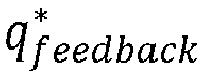
- This is just an example and any kind of closed-loop control may be used to determine the target bypass fluid flow q *( T 1 ) based on the feed line temperature T 1 , e.g. fully or partly as a closed-loop control feedback value q feedback * as follows: q feedback * K p e T + K i ⁇ e T d t , wherein K p and K i are gain factors.
- the system may further comprise a non-return valve at the bypass line downstream of the at least one bypass pump, wherein the non-return valve is configured to prevent a fluid flow through the by-pass line from the feed line to the return line. This is beneficial to prevent any backward flow which would be very inefficient in terms of energy consumption.
- the at least one pressure sensor may be arranged and configured to determine the pressure difference ⁇ p by measuring a difference between
- the system may further comprise at least one temperature sensor being arranged and configured to determine a temperature T 2 of the fluid in the return line.
- the system may further comprise at least one temperature sensor being arranged and configured to determine a temperature T 3 of the fluid in the feed line upstream of the bypass line.
- the control unit may be configured to set a target speed further based on a feed-forward control to compensate uncontrollable fluctuations of a temperature difference T 3 - T 2 between the temperature T 3 of the fluid in the feed line upstream of the bypass line and the temperature T 2 of the fluid in the return line. This is particularly advantages in case of uncontrollable fluctuations of a temperature difference T 3 - T 2 in addition to the uncontrolled fluctuations of the pressure difference between the feed line and the return line.
- the pump flow q 2 may be estimated based on a pump model, e.g. based on pump-related variables such as speed and/or power and/or pump head.
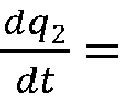
- the control unit may be optionally configured to apply, before setting the target speed based on the feed-forward control, a lowpass filter to a sum of differential flow compensation values dq 2 dt for compensating the uncontrolled fluctuations of the temperature T 3 of the fluid in the feed line upstream of the bypass line and of the temperature T 2 of the fluid in the return line.
- a lowpass filter behaves like an integration for high frequencies and outputs the feed-forward flow part q feedforward * as output of the filter.
- K may be denoted as the filter gain or transfer constant and ⁇ is the time constant.
- K may be depended on ⁇ .
- the two differential flow compensation values dq 2 dt for compensation the uncontrolled fluctuations of T 2 as well as T 3 may be summed up and fed into the low pass filter described above to get the feed-forward controlled flow part q feedforward * .
- control unit may be configured to stop the at least one bypass pump if the pump speed is below a predetermined stop speed threshold ⁇ stop .
- ⁇ stop may be defined be 10% or 15% of the maximum pump speed.
- control unit may be configured to start the at least one bypass pump if the pump speed is at or above a pre-determined start speed threshold ⁇ start .
- ⁇ start may be the same value as ⁇ stop or a different value.
- ⁇ start may be higher than ⁇ stop , e.g. 20% of the maximum pump speed.
- control unit may be configured, upon start-up of the at least one bypass pump, to ramp up the feed forward control to compensate uncontrolled fluctuations of the pressure difference ⁇ p based on a ramp up value multiplied with the determined pressure difference ⁇ p .
- a ramp up function is applied that slowly ramps up the differential pressure signal before it is fed into the pump model.
- the ramp up function may be given by ⁇ t 0 t 1 C dt, wherein C is a constant selected such that the output of the integral is 0 at time t 0 when the pump starts and 1 at time t 1 , when the time t 1 - t 0 has elapsed.
- the output of the integral is multiplied with the differential pressure signal, whereby it is slowly ramped up during the time t 1 - t 0 .
- This has the advantaged that the set point overshoot or undershoot of the target temperature T 1 is kept low if the pump model function is not accurate.
- a method for regulating a temperature of a thermal energy carrying fluid in a sector of a fluid distribution network, the fluid distribution network comprising a feed line for transporting the fluid from a thermal energy source to at least one thermal energy consumer located within the sector, a return line for transporting the fluid back from the at least one thermal energy consumer to the thermal energy source, and a by-pass line connecting the return line to the feed line for mixing fluid from the return line into the feed line.
- the method comprises the following steps:
- the method may further comprise preventing a fluid flow through the bypass line from the feed line to the return line by a non-return valve arranged at a bypass line downstream of the at least one bypass pump.
- determining the pressure difference may comprise measuring a difference between
- the method may further comprise determining a temperature T 2 of the fluid in the return line by at least one temperature sensor, and may further comprise determining a temperature T 3 of the fluid in the feed line upstream of the bypass line by at least one temperature sensor, wherein directly or indirectly controlling of the speed ⁇ of the at least one bypass pump may comprise setting a target speed ⁇ based on a feed-forward control to compensate uncontrolled fluctuations of a temperature difference T 3 - T 2 between the temperature T 3 of the fluid in the feed line upstream of the bypass line and the temperature T 2 of the fluid in the return line.
- the method may further comprise applying, before setting the target speed ⁇ based on the feed-forward control, a low pass filter to a sum of differential flow compensation values dq 2 dt for compensating the uncontrolled fluctuations of the temperature T 3 of the fluid in the feed line upstream of the bypass line and of the temperature T 2 of the fluid in the return line.
- the method may further comprise stopping the at least one bypass pump if the speed ⁇ is below a predetermined stop speed threshold ⁇ stop .
- the method may further comprise starting the at least one bypass pump if the pump speed ⁇ is at or above a predetermining start speed threshold ⁇ start .
- the method may further comprise ramping up, upon start-up of the at least one bypass pump, the feed forward control to compensate uncontrolled fluctuations of the pressure difference ⁇ p based on a ramp-up value multiplied with the determined pressure difference ⁇ p .
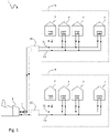
- Fig. 1 shows a fluid distribution network 1 in form of a heating distribution network.
- the fluid distribution network 1 comprises a thermal energy source 3 in form of a heat generating plant.
- the thermal energy source fluid that is pumped by a feeder pump 5 through a feed line carries thermal energy for transporting said thermal energy through the feed line from the thermal energy source 1 to a plurality of thermal energy consumers 7 in form of households.
- the thermal energy consumers 7 are located within a sector 9 of the fluid distribution network 1.
- the fluid distribution network 1 may comprise a single sector 9, or a plurality of sectors 9 as shown in Fig. 1 .
- a sector 9 of the fluid distribution network 1 may be defined by being supplied with fluid by a common feed line 11 that transports the thermal energy carrying fluid to the thermal energy consumers 7 located in the sector 9 of the fluid distribution network 1.
- the thermal energy carrying fluid delivers the thermal energy to the thermal energy consumers 7 by means of a heat exchanger 12 at each thermal energy consumer 7.
- the fluid is then returned back from the thermal energy consumers 7 to the thermal energy source 3 via a return line 13.
- the fluid distribution network 1 further comprises a system 15 for regulating the temperature of the thermal energy carrying a fluid in the sector 9.
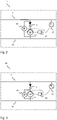
- Fig. 2 shows an embodiment of the system 15 in more detail.
- the idea is to regulate the temperature of the fluid in the sector 9 by mixing fluid from the return line 13 to the feed line 11 via a bypass line 17.
- a bypass pump 19 is installed in the bypass line 17 in order to overcome a pressure difference ⁇ p between the feed line 11 and the return line 13.
- a non-return valve 21 is installed in the bypass line downstream of the bypass pump 19. This means that the bypass pump 19 must also provide sufficient pressure for opening the non-return valve in the direction towards the feed line 11.
- a differential pressure sensor 23 is installed to determine a pressure difference ⁇ p between a pressure in the bypass line 17 upstream of the bypass pump 19 and a pressure in the bypass line 17 downstream of the non-return valve 21.
- a first temperature sensor 25 is installed in the feed line 11 downstream of the by-pass line 17 in order to determine a temperature T 1 in the feed line 11 downstream of the bypass line 17. The measurement of the first temperature sensor 25 is communicated to a control unit 27 that is configured to control directly or indirectly the speed ⁇ of the bypass pump 19.
- the pressure difference ⁇ p between the feed line 11 and the return line 13 is outside of the control of the system 15, i.e. the pressure difference ⁇ p is subject to uncontrolled or uncontrollable disturbances or fluctuations.
- Such disturbances or fluctuations of the pressure difference ⁇ p may originate from varying consumption behaviour at the thermal energy consumers 7 and/or varying circumstances at the heat generating plant.
- the inventive idea is now to control the speed of the bypass pump 19 by means of the control unit 27 based on a combination of a closed-loop control based on the determined first feed line temperature T 1 and a feed-forward control to compensate fluctuations of the pressure difference ⁇ p between the feed line 11 and the return line 13 based on the pressure difference ⁇ p determined by the differential pressure sensor 23.
- q * is the target bypass fluid flow to be provided by the bypass pump 19 and p is the pump differential pressure to compensate for the determined pressure difference ⁇ p .
- a h 1 and a h 3 are model parameters describing pump characteristics.
- the model parameters a h 1 and a h 3 may be predetermined pump-specific parameters provided by the manufacturer of the bypass pump 19.
- Fig. 9b shows a very stable feed line temperature T 1 over the time of the day despite uncontrolled fluctuations of the pressure difference ⁇ p between the feed line 11 and the return line 13.
- Fig. 3 shows another embodiment of the system 15.
- the embodiment of Fig. 3 differs from the embodiment shown in Fig. 2 by what the differential pressure sensor 23 measures.
- the differential pressure sensor 23 measures a difference between a pressure at the outlet of the bypass pump, i.e. upstream of the non-return valve 21, and a pressure at an inlet of the bypass pump 19.
- This embodiment is less advantageous in terms of controlling, because the non-return valve 19 may have under certain circumstances difficulties to settle quickly into the correct opening degree. Fluctuations of the opening degree of the non-return valve 19, however, may cause undesired disturbances of the differential pressure measurement.
- the compensating pump pressure differential p should be ramped-up more slowly at start-up of the bypass pump to avoid large overshooting or undershooting in the closed-loop control based on the feed line temperature T 1 .
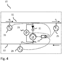
- Fig. 4 shows another embodiment of the system 15. Compared to the embodiment shown in Fig. 2 , the embodiment shown in Fig. 4 comprises two more temperature sensors, wherein a second temperature sensor 29 is installed at the return line 13 in order to determine a second temperature T 2 .
- the second temperature sensor 29 is located at the return line 13 downstream of the bypass line 17.
- the second temperature sensor 29 could be located at the return line 13 upstream of the bypass line or anywhere at the bypass line 17.
- a third temperature sensor 31 is located at the feed line 11 upstream of the bypass line 17 in order to determine a third temperature T 3 .
- the system 15 is able to compensate not only for uncontrolled fluctuations of the pressure difference between the feed line 11 and the return line 13, but also for uncontrolled fluctuations of the feed line temperature T 3 and/or the return line temperature T 2 .
- the return line temperature T 2 may be dependent on the thermal energy consumption at the thermal energy consumers 7.
- An integration over time may have a disadvantage that the feed forward flow part q feedforward * may drift over time, and control unit 27 may face a wind-up issue.
- FIG. 5 shows an embodiment of the control method described herein.
- a target feed line temperature T 1 * and the feed line temperature T 1 measured by the first temperature sensor 25 is fed into a feedback controller for a closed-loop controlled flow part q feedback * .
- the return line temperature T 2 and the feed line temperature T 3 upstream of the bypass line and the bypass fluid flow q 2 is fed into a T 2 disturbance compensator that outputs a time derivative of the bypass flow q 2 , i.e. dq 2 dT .
- time derivatives dq 2 dt are summed-up and fed into a low pass filter that behaves for high frequencies like an integration and outputs a feed-forward controlled flow part q feedforward * that is added to the closed-loop controlled flow part q feedback * .
- q * is then used as a target bypass flow into an inverse pump-model function f -1 ( q *, p ), wherein p is the pump pressure differential for compensating the determined pressure difference ⁇ p measured by the differential pressure sensor 23, and outputs a target speed ⁇ of the bypass pump 19.
- Fig. 6 shows an embodiment of the control method as shown in Fig. 5 with the difference that the pump differential pressure p is not directly fed into the inverse pump-model function at start-up of the bypass pump 19, but slowly ramped-up.
- a differential pressure sensor 23 integrated into the bypass pump 19 is used for the feed-forward control.
- a differential pressure ramp-up function in form of ⁇ t 0 t 1 C dt is multiplied with the pump differential pressure p in order to achieve a slow ramp-up.
- the constant C is chosen such that the differential pressure ramp-up function is 0 at t 0 and 1 at t 1 when the time t 1 - t 2 has elapsed.
- Fig. 7 shows another embodiment of the system 15 according to the present disclosure.
- the pressure difference ⁇ p is not determined by a single differential pressure sensor 23, but based on pressure measurements of two or more pressure sensors 33, 35, 37.
- a first pressure sensor 33 is installed at the feed line 11 downstream of the bypass line 17.
- a second pressure sensor 35 is installed at the return line 13.
- a third pressure sensor 37 is installed at the feed line 11 upstream of the bypass line 17.
- a second pump 39 installed at the feed line 11 between the bypass line 17 and the first temperature sensor 25.
- a second pump 39 may already be available or installed to boost the pressure in the feed line 11.
- the second pump 39 may be controlled by a separate second control unit 41 receiving the pressure measurements p 1 , p 2 and p 3 from the pressure sensors 35, 37, 39.
- the control units 27, 41 are preferably integrated into the bypass pump 19 and the second pump 39, respectively. Alternatively, one or more of the control units 27, 41 may be implemented in a controller separate from the pumps 19, 39.
- a third control unit 43 preferably an external programmable logic controller (PLC) is provided in addition to the control units 27, 41 that are integrated in the bypass pump 19 and the second pump 39, respectively.
- the third external control unit 41 may be signal-connected to the other control units 27, 41 by bus connections 45.
- the temperature measurements T 1 , T 2 and T 3 of the temperature sensors 25, 31, 33 are communicated to the first control unit 27 and the pressure measurements p 1 , p 2 and p 3 of the pressure sensors 35, 37, 39 are communicated to the second control unit 41.
- the external third control unit 43 may be used to carry out the control method and to command the control units 27, 41 to run the pumps 19, 39 at a certain speed.
- Fig. 9a shows an example of how the uncontrolled pressure difference ⁇ p behaves over the time of a day in the bottom plot.
- Fig. 9a shows the resulting fluctuations of the feed line temperature T 1 if the control method described herein is not applied.
- the feed line temperature T 1 fluctuates a lot due to the uncontrolled fluctuations of the pressure difference ⁇ p between the feed line 11 and the return line 13.
- the goal is to achieve a stable desired feed line temperature T 1 despite of the uncontrolled pressure fluctuations ⁇ p .
- the result of applying the control method described herein is shown in Fig. 9b .
Landscapes
- Engineering & Computer Science (AREA)
- Physics & Mathematics (AREA)
- General Physics & Mathematics (AREA)
- Automation & Control Theory (AREA)
- General Engineering & Computer Science (AREA)
- Mechanical Engineering (AREA)
- Thermal Sciences (AREA)
- Combustion & Propulsion (AREA)
- Chemical & Material Sciences (AREA)
- Water Supply & Treatment (AREA)
- Public Health (AREA)
- Health & Medical Sciences (AREA)
- Hydrology & Water Resources (AREA)
- Life Sciences & Earth Sciences (AREA)
- Fluid Mechanics (AREA)
- Flow Control (AREA)
- Control Of Positive-Displacement Pumps (AREA)
- Pipeline Systems (AREA)
Abstract
- a bypass line (17) connecting the return line (13) to the feed line (11) for mixing fluid from the return line (13) into the feed line (11),
- at least one bypass pump (19) being arranged at the bypass line (17) for pumping fluid from the return line (13) to the feed line (11),
- a control unit (27, 41, 43) being configured to directly or indirectly controla speed (ω) of the at least one bypass pump (19),
- at least one temperature sensor (25) being arranged and configured to determine a temperature (T 1) of the fluid in the feed line (11) downstream of the bypass line (17), and
- at least one pressure sensor being arranged and configured to determine an uncontrolled pressure difference (Δp) between the feed line (11) and the return line (13), or a pressure difference correlating therewith,
wherein the control unit (27, 41, 43) is configured to control the speed (ω) of the at least one bypass pump (19) based on a combination of:
- a closed-loop control to provide a fluid flow in the bypass line (17) for achieving a target feed line temperature based on the determined feed line temperature (T 1), and
- a feed-forward control to compensate fluctuations of the pressure difference (Δp) between the feed line (11) and the return line (13) based on the determined pressure difference (Δp).
Description
- The present disclosure relates to a system for regulating a temperature of a thermal energy carrying fluid in a sector of a fluid distribution network, in particular of a district heating network.
- Typically, a fluid distribution network distributes thermal power in form of hot or cold fluid to a plurality of thermal energy consumers connected to a fluid distribution network. The fluid distribution network usually comprises a plurality of sectors, wherein each sector comprises a plurality of thermal energy consumers. In case of a heating distribution network, a sector of a heating distribution network may, for instance, be a neighbourhood, a street or another kind of agglomeration of thermal energy consumers, i.e. households, commercial consumers and/or industrial consumers. A utility provider operating a heating distribution network has an interest in operating the heating distribution network as efficiently as possible. This means that a utility provider would like to regulate the temperature of the thermal energy carrying fluid in a sector of a fluid distribution network to a desired target temperature. If the temperature in a sector of a heating distribution network is too low, the thermal energy consumers are not sufficiently supplied with thermal energy and may complain. If, however, the temperature is too high, the energy loss in the heating distribution network is high.
- An idea to regulate the temperature in a sector of the heating distribution network is to mix a part of the colder fluid in a return line through a bypass line or shunt line back into a feed line supplying the sector with thermal energy carrying fluid. A pump is needed in the bypass line or shunt line, because the pressure in the feed line is higher than in the return line.
EP 2 874 039 B1 - The heat transfer system described in
EP 2 874 039 B1 - A solution to reduce the disturbances or fluctuations of the feed line temperature due to fluctuations of the uncontrolled pressure difference between the feed line and the return line could be to install a pressure reducing valve in the feed line and/or the return line of the heating distribution network. That, however, would alter the pressure balance and add hydraulic loss, and thus would reduce the efficiency of the thermal power transfer. That may not be an acceptable solution for a utility provider of a heating distribution network.
- The problem of the present disclosure is thus to control the flow in a bypass line for mixing return fluid into the feed line, despite of uncontrolled disturbances or fluctuations of the pressure difference between the feed line and the return line, in such a way that the temperature in a sector of the fluid distribution network is efficiently regulated to a stable desired target temperature.
- A solution to this problem is given by the subject matter of the independent claims. Preferred embodiments of the present disclosure are subject of the dependent subclaims, the description and the figures.
- According to a first aspect of the present disclosure, a system is provided for regulating a temperature of a thermal energy carrying fluid in sector of a fluid distribution network, the fluid distribution network comprising a feed line for transporting the fluid from a thermal energy source to at least one thermal energy consumer located within the sector and a return line for transporting the fluid back from the at least one thermal energy consumer to the thermal energy source. The system comprises
- a bypass line connecting the return line to the feed line for mixing fluid from the return line into the feed line,
- at least one bypass pump being arranged at the bypass line for pumping fluid from the return line to the feed line,
- a control unit being configured to directly or indirectly control a speed of the at least one bypass pump,
- at least one temperature sensor being arranged and configured to determine a temperature of the fluid in the feed line downstream of the bypass line, and
- at least one pressure sensor being arranged and configured to determine an uncontrolled pressure difference between the feed line and the return line, or a pressure difference correlating therewith.
- The control unit is configured to control the speed of the at least one bypass pump based on a combination of:
- a closed-loop control to provide a fluid flow in a bypass line for archiving a target feed line temperature based on the determined feed line temperature, and
- a feed-forward control to compensate fluctuations of the pressure difference between the feed line and the return line based on the determined pressure difference.
- The system is in particular suitable for regulating a temperature of a heat carrying fluid in a sector of a heating distribution network. However, the system is also applicable for other kinds of fluid distribution networks for transporting thermal energy to consumers, wherein the pressure difference between the feed line and the return line is uncontrolled or uncontrollable. The control unit may directly control the speed of the at least one bypass pump by setting a target speed or indirectly by setting a power, motor current or other operating parameter of the bypass pump that correlates with the speed. For example, the control unit may set the at least one bypass pump to run at a target percentage of the maximum speed.
- Optionally, the control unit may be configured to combine the closed-loop control and the feed-forward control by determining a target speed as a parameterised pump model-based function ω = f -1(q*(T 1),p), wherein the pump model-based function ω = f -1(q*(T 1),p) is parameterised by at least two predetermined parameters a h1, a h3. Preferably, the control unit sets a target bypass fluid flow q*(T 1) to minimise a deviation eT between the determined feed line temperature T 1 and a target feed
line temperature 


- These models may be described as a function mapping the pump flow q and the pump speed ω to the pump head h, i.e. h = f(q,ω).
- The conversion between the pump head and the pump differential pressure may be given by

- The inverse of the function f may then be used to determine a target speed ω by ω = f -1(q*(T 1),p), wherein the pump differential pressure p is set to compensate the differential pressure Δp measured by the pressure sensor, i.e. p = Δp.
- If a simple quadratic pump model is used as shown above, the target speed ω may be parameterized by two parameters a h1 and a h3 given in the formula as follows:

- The formula calculates the pump speed as a function of the set pump differential pressure and the target flow. It is advantageous as shown in the formula, to replace the squared flow by its signed counter part q*(T 1)·|q*(T 1)|. This has the advantage that, depending on the target flow q*(T 1), set by the closed-loop control to provide a fluid flow in the bypass line, the pump may be set at a higher or a lower speed of than the speed indirectly provided by the set pump differential pressure.
- The target bypass fluid flow q*(T 1) may be set to minimize a deviation

line temperature 

- Optionally, one of the at least two predetermined parameters a h1, a h3 is a no-flow parameter, e. g. a h1, indicative of the pressure provided by the at least one bypass pump at a certain speed ω and no bypass flow, i. e. q = 0.
- Optionally, the system may further comprise a non-return valve at the bypass line downstream of the at least one bypass pump, wherein the non-return valve is configured to prevent a fluid flow through the by-pass line from the feed line to the return line. This is beneficial to prevent any backward flow which would be very inefficient in terms of energy consumption.
- Optionally, the at least one pressure sensor may be arranged and configured to determine the pressure difference Δp by measuring a difference between
- a pressure in the bypass line upstream of the at least one bypass pump or in the return line, and
- a pressure downstream of the non-return valve or upstream of the non-return valve, or
- a pressure in the feed line upstream of the at least one bypass line.
- Optionally, the system may further comprise at least one temperature sensor being arranged and configured to determine a temperature T 2 of the fluid in the return line. The system may further comprise at least one temperature sensor being arranged and configured to determine a temperature T 3 of the fluid in the feed line upstream of the bypass line. The control unit may be configured to set a target speed further based on a feed-forward control to compensate uncontrollable fluctuations of a temperature difference T 3 - T 2 between the temperature T 3 of the fluid in the feed line upstream of the bypass line and the temperature T 2 of the fluid in the return line. This is particularly advantages in case of uncontrollable fluctuations of a temperature difference T 3 - T 2 in addition to the uncontrolled fluctuations of the pressure difference between the feed line and the return line. So, this is an additional feed-forward control if two more temperature sensors are available to determine the temperature T 3 of the fluid in the feed line upstream of the bypass line and the temperature T 2 of the fluid in the return line. Flow balance and energy conservation demands that: q 1(T 1 - T 2) = q 3(T 3 - T 2) and q 2(T 1 - T 2) = q 3(T 3 - T 1), wherein q 1 is the flow in the feed line downstream of the bypass line, q 2 is the flow through the bypass pump, and q 3 is the flow in the feed line upstream of the bypass line. This means that a flow differential dq 2 through the pump is needed to compensate for a change dT 2 of the return temperature according to the following formula:

- The pump flow q 2 may be estimated based on a pump model, e.g. based on pump-related variables such as speed and/or power and/or pump head. The following formula applies to the time derivatives


- A problem of the integral term in the above equation is that the feed-forward part


- The lowpass filter may be described as a transfer function H(s) in the Laplace domain by Y(s) = H(s)X(s), where Y(s) is the output of the filter and X(s) is the input of the filter. s is the Laplace variable. The complex transfer function describing the lowpass filter as a first order delay element, e.g. a pt 1-element, may be chosen to be


- In order to compensate any fluctuations of the temperature T 3 in the feed line upstream of the bypass line, the following differential aquation may be used:

- The two differential flow compensation values


- Optionally, the control unit may be configured to stop the at least one bypass pump if the pump speed is below a predetermined stop speed threshold ω stop . For example, ω stop may be defined be 10% or 15% of the maximum pump speed.
- Optionally, the control unit may be configured to start the at least one bypass pump if the pump speed is at or above a pre-determined start speed threshold ω start . ω start may be the same value as ω stop or a different value. For example, ω start may be higher than ω stop , e.g. 20% of the maximum pump speed.
- Optionally, the control unit may be configured, upon start-up of the at least one bypass pump, to ramp up the feed forward control to compensate uncontrolled fluctuations of the pressure difference Δp based on a ramp up value multiplied with the determined pressure difference Δp. In other words, a ramp up function is applied that slowly ramps up the differential pressure signal before it is fed into the pump model. The ramp up function may be given by

- According to a second aspect of the present disclosure, a method is provided for regulating a temperature of a thermal energy carrying fluid in a sector of a fluid distribution network, the fluid distribution network comprising a feed line for transporting the fluid from a thermal energy source to at least one thermal energy consumer located within the sector, a return line for transporting the fluid back from the at least one thermal energy consumer to the thermal energy source, and a by-pass line connecting the return line to the feed line for mixing fluid from the return line into the feed line. The method comprises the following steps:
- Determining a temperature T 1 of the fluid in the feed line downstream of the bypass line by at least one temperature sensor,
- Determining a pressure difference Δp between the feed line and the return by at least one pressure sensor, or a pressure difference correlating therewith,
- Directly or indirectly controlling a speed ω of at least one bypass pump being arranged at a bypass line connecting the return line to the feed line for mixing fluid from the return line into the feed line.
- a closed-loop control to provide a fluid flow in a bypass for achieving a target feed
line temperature 
- a feed-forward control to compensate uncontrolled fluctuations of the pressure difference Δp between the feed line and the return line based on the determined pressure difference Δp.
- Optionally, the combination of the closed-loop control and the feed forward control comprises determining a target speed ω as a parametrized pump model-based function ω = f -1(q*(T 1),p), wherein a target bypass fluid flow q*(T 1) is set to minimize a deviation eT between the determined feed line temperature T 1 and the target feed
line temperature 
- Optionally, one of the at least two predetermined parameters a h1, a h3, e.g. a h1, is a no-flow parameter a h1 indicative of the pressure provided by the at least one bypass pump at a certain speed ω and no bypass flow, i.e. q = 0.
- Optionally, the method may further comprise preventing a fluid flow through the bypass line from the feed line to the return line by a non-return valve arranged at a bypass line downstream of the at least one bypass pump.
- Optionally, determining the pressure difference may comprise measuring a difference between
- a pressure in the bypass line upstream of the at least one bypass pump or in the return line, and
- a pressure -downstream of the non-return valve or upstream of the non-return valve, or
- a pressure in the feed line upstream of the at least one bypass line.
- 1. between a pressure in the bypass line upstream of the at least one bypass pump and a pressure -downstream of the non-return valve;
- 2. between a pressure in the bypass line upstream of the at least one bypass pump and a pressure in the bypass line upstream of the non-return valve;
- 3. between a pressure in the bypass line upstream of the at least one bypass pump and a pressure in the feed line upstream of the at least one bypass line;
- 4. between a pressure in the return line and a pressure -downstream of the non-return valve;
- 5. between a pressure in the return line and a pressure in the bypass line upstream of the non-return valve; and
- 6. between a pressure in the return line and a pressure in the feed line upstream of the at least one bypass line.
- Optionally, the method may further comprise determining a temperature T 2 of the fluid in the return line by at least one temperature sensor, and may further comprise determining a temperature T 3 of the fluid in the feed line upstream of the bypass line by at least one temperature sensor, wherein directly or indirectly controlling of the speed ω of the at least one bypass pump may comprise setting a target speed ω based on a feed-forward control to compensate uncontrolled fluctuations of a temperature difference T 3 - T 2 between the temperature T 3 of the fluid in the feed line upstream of the bypass line and the temperature T 2 of the fluid in the return line.
- Optionally, the method may further comprise applying, before setting the target speed ω based on the feed-forward control, a low pass filter to a sum of differential flow compensation values

- Optionally, the method may further comprise stopping the at least one bypass pump if the speed ω is below a predetermined stop speed threshold ωstop.
- Optionally, the method may further comprise starting the at least one bypass pump if the pump speed ω is at or above a predetermining start speed threshold ω start .
- Optionally, the method may further comprise ramping up, upon start-up of the at least one bypass pump, the feed forward control to compensate uncontrolled fluctuations of the pressure difference Δp based on a ramp-up value multiplied with the determined pressure difference Δp.
- Embodiments of the present disclosure will be described by way of example with reference to the following figures of which:
- Fig. 1
- shows schematically an example of a heating distribution network comprising a system according to the present disclosure;
- Fig. 2
- shows schematically a first embodiment of a system according to the present disclosure;
- Fig. 3
- shows a schematically another embodiment of a system according to the present disclosure;
- Fig. 4
- show schematically a further embodiment of a system according to the present disclosure;
- Fig. 5
- shows schematically an embodiment of the control method according to the present disclosure;
- Fig. 6
- shows schematically a further embodiment of a control method according to the present disclosure;
- Fig. 7
- shows schematically a further embodiment of a system according to the present disclosure;
- Fig. 8
- shows schematically a further embodiment of a system according to the present disclosure; and
- Fig. 9a,b
- show a feed line temperature T 1 downstream of the bypass line and a pressure difference Δp over the time of the day in
Fig. 9a without applying the control method according to the present disclosure and inFig. 9b with applying the control method according to the present disclosure. -
Fig. 1 shows afluid distribution network 1 in form of a heating distribution network. Thefluid distribution network 1 comprises athermal energy source 3 in form of a heat generating plant. The thermal energy source fluid that is pumped by afeeder pump 5 through a feed line carries thermal energy for transporting said thermal energy through the feed line from thethermal energy source 1 to a plurality ofthermal energy consumers 7 in form of households. Thethermal energy consumers 7 are located within asector 9 of thefluid distribution network 1. Thefluid distribution network 1 may comprise asingle sector 9, or a plurality ofsectors 9 as shown inFig. 1 . Asector 9 of thefluid distribution network 1 may be defined by being supplied with fluid by acommon feed line 11 that transports the thermal energy carrying fluid to thethermal energy consumers 7 located in thesector 9 of thefluid distribution network 1. The thermal energy carrying fluid delivers the thermal energy to thethermal energy consumers 7 by means of aheat exchanger 12 at eachthermal energy consumer 7. The fluid is then returned back from thethermal energy consumers 7 to thethermal energy source 3 via areturn line 13. Thefluid distribution network 1 further comprises asystem 15 for regulating the temperature of the thermal energy carrying a fluid in thesector 9. -
Fig. 2 shows an embodiment of thesystem 15 in more detail. The idea is to regulate the temperature of the fluid in thesector 9 by mixing fluid from thereturn line 13 to thefeed line 11 via abypass line 17. As the pressure in thefeed line 11 exceeds a pressure in thereturn line 13, abypass pump 19 is installed in thebypass line 17 in order to overcome a pressure difference Δp between thefeed line 11 and thereturn line 13. In order to prevent any backflow through thebypass line 17 from thefeed line 11 to thereturn line 13, anon-return valve 21 is installed in the bypass line downstream of thebypass pump 19. This means that thebypass pump 19 must also provide sufficient pressure for opening the non-return valve in the direction towards thefeed line 11. Adifferential pressure sensor 23 is installed to determine a pressure difference Δp between a pressure in thebypass line 17 upstream of thebypass pump 19 and a pressure in thebypass line 17 downstream of thenon-return valve 21. Afirst temperature sensor 25 is installed in thefeed line 11 downstream of the by-pass line 17 in order to determine a temperature T 1 in thefeed line 11 downstream of thebypass line 17. The measurement of thefirst temperature sensor 25 is communicated to acontrol unit 27 that is configured to control directly or indirectly the speed ω of thebypass pump 19. - One could think that it is now sufficient to simply control the speed ω of the
bypass pump 19 in a closed-loop manner based on the temperature T 1 measured by thefirst temperature sensor 25 as a feedback value. It has shown, however, that this does not work very well, because the temperature T 1 may be difficult to stabilise and may fluctuate too much as can be seen in the upper plot ofFig. 9a . The reason for this is that thefirst temperature sensor 25 is placed at a certain distance to thebypass line 17 downstream at thefeed line 11 in order to measure the fluid temperature where it is sufficiently mixed downstream of thebypass line 17. Consequently, there is a relatively large time delay between a change of the speed ω of thebypass pump 19 and the result showing in a change of the temperature T 1 at thefirst temperature sensor 25. In addition, the pressure difference Δp between thefeed line 11 and thereturn line 13 is outside of the control of thesystem 15, i.e. the pressure difference Δp is subject to uncontrolled or uncontrollable disturbances or fluctuations. Such disturbances or fluctuations of the pressure difference Δp may originate from varying consumption behaviour at thethermal energy consumers 7 and/or varying circumstances at the heat generating plant. Any fluctuation of the pressure difference Δp between thefeed line 11 and thereturn line 13, however, strongly affects the effect of thebypass pump 19. Therefore, the measurement of the pressure difference Δp by thedifferential pressure sensor 23 is also communicated to thecontrol unit 27 in order to perform a feed-forward control to compensate for the fluctuations of the pressure difference Δp. The inventive idea is now to control the speed of thebypass pump 19 by means of thecontrol unit 27 based on a combination of a closed-loop control based on the determined first feed line temperature T 1 and a feed-forward control to compensate fluctuations of the pressure difference Δp between thefeed line 11 and thereturn line 13 based on the pressure difference Δp determined by thedifferential pressure sensor 23. For example, thecontrol unit 27 may be configured to set a target speed
bypass pump 19 and p is the pump differential pressure to compensate for the determined pressure difference Δp. a h1 and a h3 are model parameters describing pump characteristics. The model parameters a h1 and a h3 may be predetermined pump-specific parameters provided by the manufacturer of thebypass pump 19. For example, one of the parameters a h1 and a h3 is a now-flow parameter indicative of the pressure provide by thebypass pump 19 at a certain speed ω and no bypass flow, i.e. q = 0. The target bypass fluid flow q*(T 1) is set in a closed-loop manner to minimize a deviation
temperate 
Fig. 9b , which shows a very stable feed line temperature T 1 over the time of the day despite uncontrolled fluctuations of the pressure difference Δp between thefeed line 11 and thereturn line 13. -
Fig. 3 shows another embodiment of thesystem 15. The embodiment ofFig. 3 differs from the embodiment shown inFig. 2 by what thedifferential pressure sensor 23 measures. InFig. 3 , thedifferential pressure sensor 23 measures a difference between a pressure at the outlet of the bypass pump, i.e. upstream of thenon-return valve 21, and a pressure at an inlet of thebypass pump 19. This has the advantage that thepressure sensor 23 may be pre-installed at and/or integrated into thebypass pump 19. This embodiment, however, is less advantageous in terms of controlling, because thenon-return valve 19 may have under certain circumstances difficulties to settle quickly into the correct opening degree. Fluctuations of the opening degree of thenon-return valve 19, however, may cause undesired disturbances of the differential pressure measurement. This means that the compensating pump pressure differential p should be ramped-up more slowly at start-up of the bypass pump to avoid large overshooting or undershooting in the closed-loop control based on the feed line temperature T 1. -
Fig. 4 shows another embodiment of thesystem 15. Compared to the embodiment shown inFig. 2 , the embodiment shown inFig. 4 comprises two more temperature sensors, wherein asecond temperature sensor 29 is installed at thereturn line 13 in order to determine a second temperature T 2. InFig. 4 , thesecond temperature sensor 29 is located at thereturn line 13 downstream of thebypass line 17. Alternatively, thesecond temperature sensor 29 could be located at thereturn line 13 upstream of the bypass line or anywhere at thebypass line 17. Athird temperature sensor 31 is located at thefeed line 11 upstream of thebypass line 17 in order to determine a third temperature T 3. With these additional temperature measurements T 2 and T 3, thesystem 15 is able to compensate not only for uncontrolled fluctuations of the pressure difference between thefeed line 11 and thereturn line 13, but also for uncontrolled fluctuations of the feed line temperature T 3 and/or the return line temperature T 2. In particular, the return line temperature T 2 may be dependent on the thermal energy consumption at thethermal energy consumers 7. Energy conservation and flow balance demands that the following equations apply: q 1(T 1 - T 2) = q 3(T 3 - T 2) and q 2(T 1 - T 2) = q 3(T 3 - T 1), wherein q 1 is the feed line flow downstream of thebypass line 17 at thefirst temperature sensor 25, q 2 is the bypass flow through thebypass pump 19, and q 3 is the feed line flow upstream of thebypass line 17 at thethird temperature sensor 31. In order to compensate a fluctuation dT 2 of the return line temperature T 2, the bypass flow q 2 must be changed by dq 2 as follows:
- Over time, an uncontrolled fluctuation of the return line temperature T 2 could be compensated by a feed-forward controlled flow part



control unit 27 may face a wind-up issue. - A solution to this problem is shown in
Fig. 5 , which shows an embodiment of the control method described herein. A target feedline temperature 
first temperature sensor 25 is fed into a feedback controller for a closed-loop controlled flow part


differential pressure sensor 23, and outputs a target speed ω of thebypass pump 19. -
Fig. 6 shows an embodiment of the control method as shown inFig. 5 with the difference that the pump differential pressure p is not directly fed into the inverse pump-model function at start-up of thebypass pump 19, but slowly ramped-up. This is particularly advantageous for a system according to the embodiment shown inFig. 3 , wherein adifferential pressure sensor 23 integrated into thebypass pump 19 is used for the feed-forward control. A differential pressure ramp-up function in form of
-
Fig. 7 shows another embodiment of thesystem 15 according to the present disclosure. In contrast to the previously described embodiments, the pressure difference Δp is not determined by a singledifferential pressure sensor 23, but based on pressure measurements of two ormore pressure sensors first pressure sensor 33 is installed at thefeed line 11 downstream of thebypass line 17. Asecond pressure sensor 35 is installed at thereturn line 13. Athird pressure sensor 37 is installed at thefeed line 11 upstream of thebypass line 17. The pressure difference Δp is then given by Δp = p 3 - p 2, wherein p 2 is the pressure measured by thesecond pressure sensor 35 and p 3 is the pressure measured by thethird pressure sensor 37. In the embodiment shown inFig. 7 , there is asecond pump 39 installed at thefeed line 11 between thebypass line 17 and thefirst temperature sensor 25. Such asecond pump 39 may already be available or installed to boost the pressure in thefeed line 11. Thesecond pump 39 may be controlled by a separatesecond control unit 41 receiving the pressure measurements p 1, p 2 and p 3 from thepressure sensors second control unit 41 is in signal connection with thecontrol unit 27 for controlling the speed of thebypass pump 19 and passes on the information about the pressure difference Δp = p 3 - p 2 to thecontrol unit 27 for the feed-forward control to regulate the bypass flow accordingly. Thecontrol units bypass pump 19 and thesecond pump 39, respectively. Alternatively, one or more of thecontrol units pumps - As shown in
Fig. 8 , athird control unit 43, preferably an external programmable logic controller (PLC), is provided in addition to thecontrol units bypass pump 19 and thesecond pump 39, respectively. The thirdexternal control unit 41 may be signal-connected to theother control units bus connections 45. The temperature measurements T 1, T 2 and T 3 of thetemperature sensors first control unit 27 and the pressure measurements p 1, p 2 and p 3 of thepressure sensors second control unit 41. The externalthird control unit 43 may be used to carry out the control method and to command thecontrol units pumps -
Fig. 9a shows an example of how the uncontrolled pressure difference Δp behaves over the time of a day in the bottom plot. In the top plot,Fig. 9a shows the resulting fluctuations of the feed line temperature T 1 if the control method described herein is not applied. As can be seen, the feed line temperature T 1 fluctuates a lot due to the uncontrolled fluctuations of the pressure difference Δp between thefeed line 11 and thereturn line 13. Such a situation is not tolerable for a utility provider operating thefluid distribution network 1. The goal is to achieve a stable desired feed line temperature T 1 despite of the uncontrolled pressure fluctuations Δp. The result of applying the control method described herein is shown inFig. 9b . The pressure fluctuations are still uncontrolled and present over the time of the day, but the feed line temperature T 1 is very stable within a small band about a target feedline temperature 
-
- 1
- fluid distribution network
- 3
- thermal energy source
- 5
- feeder pump
- 7
- thermal energy consumers
- 9
- sector of fluid distribution network
- 11
- feed line
- 12
- heat exchanger
- 13
- return line
- 15
- system
- 17
- bypass line
- 19
- bypass pump
- 21
- non-return valve
- 23
- differential pressure sensor
- 25
- first temperature sensor
- 27
- first control unit
- 29
- second temperature sensor
- 31
- third temperature sensor
- 33
- first pressure sensor
- 35
- second pressure sensor
- 37
- third pressure sensor
- 39
- second pump
- 41
- second control unit
- 43
- third control unit
- 45
- bus connection
Claims (16)
- A system (15) for regulating a temperature of a thermal energy carrying fluid in a sector (9) of a fluid distribution network (1), the fluid distribution network (1) comprising a feed line (11) for transporting the fluid from a thermal energy source (3) to at least one thermal energy consumer (7) located within the sector (9) and a return line (13) for transporting the fluid back from the at least one thermal energy consumer (7) to the thermal energy source (3), wherein the system (15) comprises- a bypass line (17) connecting the return line (13) to the feed line (11) for mixing fluid from the return line (13) into the feed line (11),- at least one bypass pump (19) being arranged at the by-pass line (17) for pumping fluid from the return line (13) to the feed line (11),- a control unit (27, 41, 43) being configured to directly or indirectly control a speed (ω) of the at least one bypass pump (19),- at least one temperature sensor (25) being arranged and configured to determine a temperature (T 1) of the fluid in the feed line (11) downstream of the bypass line (17), and- at least one pressure sensor being arranged and configured to determine an uncontrolled pressure difference (Δp) between the feed line (11) and the return line (13), or a pressure difference correlating therewith,wherein the control unit (27, 41, 43) is configured to control the speed (ω) of the at least one bypass pump (19) based on a combination of:- a closed-loop control to provide a fluid flow in the bypass line (17) for achieving a target feed line temperature based on the determined feed line temperature (T 1), and- a feed-forward control to compensate fluctuations of the pressure difference (Δp) between the feed line (11) and the return line (13) based on the determined pressure difference (Δρ).
- The system (15) according to claim 1, wherein the control unit (27, 41, 43) is configured to combine the closed-loop control and the feed-forward control by determining a target speed (ω) as a parametrised pump model-based function ω = f -1(q*(T 1),p), wherein the pump model-based function ω = f -1(q*(T 1),p) is parametrised by at least two pre-determined parameters a h1, a h3.
- The system (15) according to any of the preceding claims, wherein the control unit (27, 41, 43) is configured to set a target bypass fluid flow q*(T 1) to minimize a deviation


- The system (15) according to any of the preceding claims, wherein the control unit (27, 41, 43) is configured to set a pump differential pressure p to compensate for the determined pressure difference Δp.
- The system (15) according to any of the preceding claims, further comprising a non-return valve at the bypass line (17) downstream of the at least one bypass pump (19), wherein the non-return valve (21) is configured to prevent a fluid flow through the bypass line (17) from the feed line (11) to the return line (13).
- The system (15) according to claim 5, wherein the at least one pressure sensor is arranged and configured to determine the pressure difference (Δp) by measuring a difference between- a pressure in the bypass line (17) upstream of the at least one bypass pump (19) or in the return line (13), and- a pressure downstream of the non-return valve (21) or upstream of the non-return valve (21), or a pressure in the feed line (11) upstream of the at least one bypass line (17).
- The system (15) according to any of the preceding claims, further comprising at least one temperature sensor (29) being arranged and configured to determine a temperature (T 2) of the fluid in the return line (13), and further comprising at least one temperature sensor (31) being arranged and configured to determine a temperature (T 3) of the fluid in the feed line (11) upstream of the bypass line (17), wherein the control unit (27, 41, 43) is configured to set a target speed (ω) based on a feed-forward control to compensate uncontrolled fluctuations of a temperature difference (T3 - T 2) between the temperature (T 3) of the fluid in the feed line (11) upstream of the bypass line (17) and the temperature (T 2) of the fluid in the return line (13).
- The system (15) according to any of the preceding claims, wherein the control unit (27, 41, 43) is configured to stop the at least one bypass pump (19) if the speed (ω) is below a pre-determined stop speed threshold (ωstop ), and wherein the control unit (27, 41, 43) is configured to start the at least one bypass pump (19) if the speed (ω) is at or above a pre-determined start speed threshold (ωstart ).
- The system (15) according to any of the preceding claims, wherein the control unit (27, 41, 43) is configured, upon start-up of the at least one bypass pump (19), to ramp up the feed-forward control to compensate uncontrolled fluctuations of the pressure difference (Δρ) based on a ramp-up value multiplied with the determined pressure difference (Δp).
- A method for regulating a temperature of a thermal energy carrying fluid in a sector (9) of a fluid distribution network (1), the fluid distribution network (1) comprising a feed line (11) for transporting the fluid from a thermal energy source (3) to at least one thermal energy consumer (7) located within the sector (9), a return line (13) for transporting the fluid back from the at least one thermal energy consumer (7) to the thermal energy source (3), and a bypass line (17) connecting the return line (13) to the feed line (11) for mixing fluid from the return line (13) into the feed line (11), wherein the method comprises- determining a temperature (T 1) of the fluid in the feed line (11) downstream of the bypass line (17) by at least one temperature sensor (25),- determining a pressure difference (Δp) between the feed line (11) and the return line (13) by at least one pressure sensor, or a pressure difference correlating therewith,- directly or indirectly controlling a speed (ω) of at least one by-pass pump (19) being arranged at a bypass line (17) connecting the return line (13) to the feed line (11) for mixing fluid from the return line (13) into the feed line (11),wherein said directly or indirectly controlling of the speed (ω) of the at least one bypass pump (19) is based on a combination of:- a closed-loop control to provide a fluid flow in the bypass line (17) for achieving a target feed line (11) temperature based on the determined feed line temperature (T 1), and- a feed-forward control to compensate uncontrolled fluctuations of the pressure difference (Δp) between the feed line (11) and the return line (13) based on the determined pressure difference (Δp).
- The method according to claim 10, wherein combination of the closed-loop control and the feed-forward control comprises determining a target speed (ω) as a parametrised pump model-based function ω = f -1(q*(T 1),p), wherein a target bypass fluid flow q*(T 1) is set to minimize a deviation


- The method according to claim 10 or 11, further comprising preventing a fluid flow through the bypass line (17) from the feed line (11) to the return line (13) by a non-return valve (21) arranged at the bypass line (17) downstream of the at least one bypass pump (19).
- The method according to claim 12, wherein determining the pressure difference (Δp) comprises measuring a difference between- a pressure in the bypass line (17) upstream of the at least one bypass pump (19) or in the return line (13), and- a pressure downstream of the non-return valve (21) or upstream of the non-return valve (21), or a pressure in the feed line (11) upstream of the at least one bypass line (17).
- The method according to any of the claims 10 to 13, further comprising determining a temperature (T 2) of the fluid in the return line (13) by at least one temperature sensor (29), and further comprising determining a temperature (T 3) of the fluid in the feed line (11) upstream of the bypass line (17) by at least one temperature sensor (31), wherein directly or indirectly controlling of the speed (ω) of the at least one bypass pump (19) comprises setting a target speed (ω) based on a feed-forward control to compensate uncontrolled fluctuations of a temperature difference (T 3 - T 2) between the temperature (T 3) of the fluid in the feed line (11) upstream of the bypass line (17) and the temperature (T 2) of the fluid in the return line (13).
- The method according to any of the claims 10 to 14, further comprising stopping the at least one bypass pump (19) if the speed (ω) is below a pre-determined stop speed threshold (ωstop ), and further comprising starting the at least one bypass pump (19) if the speed (ω) is at or above a pre-determined start speed threshold (ωstart ).
- The method according to any of the claims 10 to 15, further comprising ramping up, upon start-up of the at least one bypass pump (19), the feed-forward control to compensate uncontrolled fluctuations of the pressure difference (Δp) based on a ramp-up value multiplied with the determined pressure difference (Δp).
Priority Applications (4)
| Application Number | Priority Date | Filing Date | Title |
|---|---|---|---|
| EP21184830.4A EP4116791B1 (en) | 2021-07-09 | 2021-07-09 | System for regulating a temperature of a thermal energy carrying fluid in a sector of a fluid distribution network |
| KR1020220078965A KR102988103B1 (en) | 2021-07-09 | 2022-06-28 | System for regulating a temperature of a thermal energy carrying fluid in a sector of a fluid distribution network |
| US17/859,127 US12331494B2 (en) | 2021-07-09 | 2022-07-07 | System for regulating a temperature of a thermal energy carrying fluid in a sector of a fluid distribution network |
| CN202210813016.9A CN115599142A (en) | 2021-07-09 | 2022-07-11 | System for regulating the temperature of a thermal energy-carrying fluid in a section of a fluid distribution network |
Applications Claiming Priority (1)
| Application Number | Priority Date | Filing Date | Title |
|---|---|---|---|
| EP21184830.4A EP4116791B1 (en) | 2021-07-09 | 2021-07-09 | System for regulating a temperature of a thermal energy carrying fluid in a sector of a fluid distribution network |
Publications (3)
| Publication Number | Publication Date |
|---|---|
| EP4116791A1 true EP4116791A1 (en) | 2023-01-11 |
| EP4116791B1 EP4116791B1 (en) | 2025-01-08 |
| EP4116791C0 EP4116791C0 (en) | 2025-01-08 |
Family
ID=77155509
Family Applications (1)
| Application Number | Title | Priority Date | Filing Date |
|---|---|---|---|
| EP21184830.4A Active EP4116791B1 (en) | 2021-07-09 | 2021-07-09 | System for regulating a temperature of a thermal energy carrying fluid in a sector of a fluid distribution network |
Country Status (4)
| Country | Link |
|---|---|
| US (1) | US12331494B2 (en) |
| EP (1) | EP4116791B1 (en) |
| KR (1) | KR102988103B1 (en) |
| CN (1) | CN115599142A (en) |
Cited By (1)
| Publication number | Priority date | Publication date | Assignee | Title |
|---|---|---|---|---|
| CN119617956A (en) * | 2025-02-12 | 2025-03-14 | 常州常成热力设备有限公司 | Heat exchanger for reducing energy consumption |
Families Citing this family (2)
| Publication number | Priority date | Publication date | Assignee | Title |
|---|---|---|---|---|
| CN116378167B (en) * | 2023-04-04 | 2025-08-01 | 深圳市康基恒业科技有限公司 | Circulation loop converging and merging system among multiple buildings in park and control method thereof |
| CN117008469A (en) * | 2023-06-16 | 2023-11-07 | 东南大学 | Dynamic feedforward compensation control method and system for rapid load change of thermal power units |
Citations (3)
| Publication number | Priority date | Publication date | Assignee | Title |
|---|---|---|---|---|
| US20160195092A1 (en) * | 2013-08-14 | 2016-07-07 | Orcan Energy Ag | Performance map control of centrifugal pumps |
| EP2874039B1 (en) | 2013-11-19 | 2017-03-29 | Grundfos Holding A/S | Control method for a heat transfer system and heat transfer system |
| EP3809051A1 (en) * | 2019-10-14 | 2021-04-21 | Grundfos Holding A/S | District heating system |
Family Cites Families (10)
| Publication number | Priority date | Publication date | Assignee | Title |
|---|---|---|---|---|
| JP2874039B1 (en) | 1998-04-06 | 1999-03-24 | パラマウントベッド株式会社 | Back raising mechanism for bed with interlocking displacement function of bottom supporting head |
| US6536464B1 (en) * | 2000-10-25 | 2003-03-25 | Grundfos Pumps Manufacturing Corporation | Thermostatically controlled bypass valve and water circulating system for same |
| US7308906B2 (en) * | 2004-02-23 | 2007-12-18 | Ross Sinclaire | Multi-story water distribution system |
| KR100937446B1 (en) | 2009-06-22 | 2010-01-19 | 한상철 | Piping apparatus of the pressure differential control valve |
| AU2010200354A1 (en) * | 2010-02-01 | 2011-08-18 | Ford Motor Company Of Australia Limited | Liquid Fuel Injection Engine |
| KR101047423B1 (en) * | 2010-06-24 | 2011-07-07 | 주식회사 대영파워펌프 | Differential pressure proportional control method of air-conditioning system |
| EP3623896B1 (en) * | 2018-09-12 | 2021-04-28 | Fimcim S.P.A. | Method and device for controlling the flow of a fluid in an air-conditioning and/or heating system |
| DK180868B1 (en) | 2018-10-23 | 2022-06-08 | Frese As | District heating system and methods for flow control and retrofitting of a flow control system in a district heating system |
| JP7250249B2 (en) * | 2019-04-19 | 2023-04-03 | マツダ株式会社 | Abnormality determination method and abnormality determination system for differential pressure sensor |
| EP3734396B1 (en) * | 2019-04-29 | 2021-09-08 | Grundfos Holding A/S | Control system and method for controlling a fluid distribution system |
-
2021
- 2021-07-09 EP EP21184830.4A patent/EP4116791B1/en active Active
-
2022
- 2022-06-28 KR KR1020220078965A patent/KR102988103B1/en active Active
- 2022-07-07 US US17/859,127 patent/US12331494B2/en active Active
- 2022-07-11 CN CN202210813016.9A patent/CN115599142A/en active Pending
Patent Citations (3)
| Publication number | Priority date | Publication date | Assignee | Title |
|---|---|---|---|---|
| US20160195092A1 (en) * | 2013-08-14 | 2016-07-07 | Orcan Energy Ag | Performance map control of centrifugal pumps |
| EP2874039B1 (en) | 2013-11-19 | 2017-03-29 | Grundfos Holding A/S | Control method for a heat transfer system and heat transfer system |
| EP3809051A1 (en) * | 2019-10-14 | 2021-04-21 | Grundfos Holding A/S | District heating system |
Cited By (1)
| Publication number | Priority date | Publication date | Assignee | Title |
|---|---|---|---|---|
| CN119617956A (en) * | 2025-02-12 | 2025-03-14 | 常州常成热力设备有限公司 | Heat exchanger for reducing energy consumption |
Also Published As
| Publication number | Publication date |
|---|---|
| CN115599142A (en) | 2023-01-13 |
| EP4116791B1 (en) | 2025-01-08 |
| EP4116791C0 (en) | 2025-01-08 |
| US12331494B2 (en) | 2025-06-17 |
| KR20230009823A (en) | 2023-01-17 |
| US20230018443A1 (en) | 2023-01-19 |
| KR102988103B1 (en) | 2026-07-07 |
Similar Documents
| Publication | Publication Date | Title |
|---|---|---|
| US12331494B2 (en) | System for regulating a temperature of a thermal energy carrying fluid in a sector of a fluid distribution network | |
| US10690423B2 (en) | Method for a heat transfer system and heat transfer system | |
| US9810438B2 (en) | Controlled hydronic distribution system | |
| EP3734396B1 (en) | Control system and method for controlling a fluid distribution system | |
| US8754720B2 (en) | Two-stage pulse signal controller | |
| CN1202616A (en) | Fluid flow rate measuring and controlling device and method | |
| KR102162694B1 (en) | Apparatus and method for controlling temperature of supplying gas | |
| EP1659294B1 (en) | Compressor control unit and gas turbine power plant including this unit | |
| US20170060145A1 (en) | System and method for speed control of variable speed pumping systems | |
| EP2372260B1 (en) | Method for heating water according to the circulation principle and water heating system | |
| MXPA06015164A (en) | Closed-loop, valve-based transmission control algorithm. | |
| RU2325591C1 (en) | Automatic regulation of heat flow in heating network for dual-flow heating system | |
| CN115030824B (en) | Self-adaptive oil supply system and method under full flight profile of helicopter | |
| EP4194762A1 (en) | Method for adjusting a desired feed temperature in a heat transfer system and a heat transfer system | |
| US11713718B2 (en) | Dual valve fluid metering system | |
| EP2192292B1 (en) | Speed control governor | |
| JP4582396B2 (en) | Water pump control system | |
| CN113348617A (en) | Process control using amplitude control loop | |
| EP3506043B1 (en) | Method for controlling a heating or cooling system | |
| EP3407153B1 (en) | Control of pressure controller at border values | |
| CN100489412C (en) | Feed pump control system | |
| JPS58158444A (en) | Fluid heating control device | |
| JP5460425B2 (en) | Water supply pressure control system and method | |
| CN116382064A (en) | Method for controlling a centrifugal pump | |
| JP2737202B2 (en) | Water turbine guide vane control device |
Legal Events
| Date | Code | Title | Description |
|---|---|---|---|
| PUAI | Public reference made under article 153(3) epc to a published international application that has entered the european phase |
Free format text: ORIGINAL CODE: 0009012 |
|
| STAA | Information on the status of an ep patent application or granted ep patent |
Free format text: STATUS: THE APPLICATION HAS BEEN PUBLISHED |
|
| AK | Designated contracting states |
Kind code of ref document: A1 Designated state(s): AL AT BE BG CH CY CZ DE DK EE ES FI FR GB GR HR HU IE IS IT LI LT LU LV MC MK MT NL NO PL PT RO RS SE SI SK SM TR |
|
| STAA | Information on the status of an ep patent application or granted ep patent |
Free format text: STATUS: REQUEST FOR EXAMINATION WAS MADE |
|
| 17P | Request for examination filed |
Effective date: 20230703 |
|
| RBV | Designated contracting states (corrected) |
Designated state(s): AL AT BE BG CH CY CZ DE DK EE ES FI FR GB GR HR HU IE IS IT LI LT LU LV MC MK MT NL NO PL PT RO RS SE SI SK SM TR |
|
| GRAP | Despatch of communication of intention to grant a patent |
Free format text: ORIGINAL CODE: EPIDOSNIGR1 |
|
| STAA | Information on the status of an ep patent application or granted ep patent |
Free format text: STATUS: GRANT OF PATENT IS INTENDED |
|
| INTG | Intention to grant announced |
Effective date: 20240611 |
|
| GRAJ | Information related to disapproval of communication of intention to grant by the applicant or resumption of examination proceedings by the epo deleted |
Free format text: ORIGINAL CODE: EPIDOSDIGR1 |
|
| STAA | Information on the status of an ep patent application or granted ep patent |
Free format text: STATUS: REQUEST FOR EXAMINATION WAS MADE |
|
| INTC | Intention to grant announced (deleted) | ||
| GRAP | Despatch of communication of intention to grant a patent |
Free format text: ORIGINAL CODE: EPIDOSNIGR1 |
|
| STAA | Information on the status of an ep patent application or granted ep patent |
Free format text: STATUS: GRANT OF PATENT IS INTENDED |
|
| INTG | Intention to grant announced |
Effective date: 20240826 |
|
| GRAS | Grant fee paid |
Free format text: ORIGINAL CODE: EPIDOSNIGR3 |
|
| GRAA | (expected) grant |
Free format text: ORIGINAL CODE: 0009210 |
|
| STAA | Information on the status of an ep patent application or granted ep patent |
Free format text: STATUS: THE PATENT HAS BEEN GRANTED |
|
| AK | Designated contracting states |
Kind code of ref document: B1 Designated state(s): AL AT BE BG CH CY CZ DE DK EE ES FI FR GB GR HR HU IE IS IT LI LT LU LV MC MK MT NL NO PL PT RO RS SE SI SK SM TR |
|
| REG | Reference to a national code |
Ref country code: GB Ref legal event code: FG4D |
|
| REG | Reference to a national code |
Ref country code: CH Ref legal event code: EP |
|
| REG | Reference to a national code |
Ref country code: DE Ref legal event code: R096 Ref document number: 602021024578 Country of ref document: DE |
|
| REG | Reference to a national code |
Ref country code: IE Ref legal event code: FG4D |
|
| U01 | Request for unitary effect filed |
Effective date: 20250120 |
|
| U07 | Unitary effect registered |
Designated state(s): AT BE BG DE DK EE FI FR IT LT LU LV MT NL PT RO SE SI Effective date: 20250124 |
|
| U1O | Appointed representative for the unitary patent procedure deleted after the registration of the unitary effect | ||
| PG25 | Lapsed in a contracting state [announced via postgrant information from national office to epo] |
Ref country code: RS Free format text: LAPSE BECAUSE OF FAILURE TO SUBMIT A TRANSLATION OF THE DESCRIPTION OR TO PAY THE FEE WITHIN THE PRESCRIBED TIME-LIMIT Effective date: 20250408 |
|
| PG25 | Lapsed in a contracting state [announced via postgrant information from national office to epo] |
Ref country code: PL Free format text: LAPSE BECAUSE OF FAILURE TO SUBMIT A TRANSLATION OF THE DESCRIPTION OR TO PAY THE FEE WITHIN THE PRESCRIBED TIME-LIMIT Effective date: 20250108 |
|
| PG25 | Lapsed in a contracting state [announced via postgrant information from national office to epo] |
Ref country code: ES Free format text: LAPSE BECAUSE OF FAILURE TO SUBMIT A TRANSLATION OF THE DESCRIPTION OR TO PAY THE FEE WITHIN THE PRESCRIBED TIME-LIMIT Effective date: 20250108 |
|
| PG25 | Lapsed in a contracting state [announced via postgrant information from national office to epo] |
Ref country code: NO Free format text: LAPSE BECAUSE OF FAILURE TO SUBMIT A TRANSLATION OF THE DESCRIPTION OR TO PAY THE FEE WITHIN THE PRESCRIBED TIME-LIMIT Effective date: 20250408 Ref country code: IS Free format text: LAPSE BECAUSE OF FAILURE TO SUBMIT A TRANSLATION OF THE DESCRIPTION OR TO PAY THE FEE WITHIN THE PRESCRIBED TIME-LIMIT Effective date: 20250508 |
|
| PG25 | Lapsed in a contracting state [announced via postgrant information from national office to epo] |
Ref country code: HR Free format text: LAPSE BECAUSE OF FAILURE TO SUBMIT A TRANSLATION OF THE DESCRIPTION OR TO PAY THE FEE WITHIN THE PRESCRIBED TIME-LIMIT Effective date: 20250108 |
|
| PG25 | Lapsed in a contracting state [announced via postgrant information from national office to epo] |
Ref country code: GR Free format text: LAPSE BECAUSE OF FAILURE TO SUBMIT A TRANSLATION OF THE DESCRIPTION OR TO PAY THE FEE WITHIN THE PRESCRIBED TIME-LIMIT Effective date: 20250409 |
|
| U20 | Renewal fee for the european patent with unitary effect paid |
Year of fee payment: 5 Effective date: 20250728 |
|
| PG25 | Lapsed in a contracting state [announced via postgrant information from national office to epo] |
Ref country code: SM Free format text: LAPSE BECAUSE OF FAILURE TO SUBMIT A TRANSLATION OF THE DESCRIPTION OR TO PAY THE FEE WITHIN THE PRESCRIBED TIME-LIMIT Effective date: 20250108 |
|
| PGFP | Annual fee paid to national office [announced via postgrant information from national office to epo] |
Ref country code: GB Payment date: 20250724 Year of fee payment: 5 |
|
| PG25 | Lapsed in a contracting state [announced via postgrant information from national office to epo] |
Ref country code: CZ Free format text: LAPSE BECAUSE OF FAILURE TO SUBMIT A TRANSLATION OF THE DESCRIPTION OR TO PAY THE FEE WITHIN THE PRESCRIBED TIME-LIMIT Effective date: 20250108 |
|
| PG25 | Lapsed in a contracting state [announced via postgrant information from national office to epo] |
Ref country code: SK Free format text: LAPSE BECAUSE OF FAILURE TO SUBMIT A TRANSLATION OF THE DESCRIPTION OR TO PAY THE FEE WITHIN THE PRESCRIBED TIME-LIMIT Effective date: 20250108 |
|
| PLBE | No opposition filed within time limit |
Free format text: ORIGINAL CODE: 0009261 |
|
| STAA | Information on the status of an ep patent application or granted ep patent |
Free format text: STATUS: NO OPPOSITION FILED WITHIN TIME LIMIT |
|
| REG | Reference to a national code |
Ref country code: CH Ref legal event code: L10 Free format text: ST27 STATUS EVENT CODE: U-0-0-L10-L00 (AS PROVIDED BY THE NATIONAL OFFICE) Effective date: 20251119 |
|
| 26N | No opposition filed |
Effective date: 20251009 |
|
| REG | Reference to a national code |
Ref country code: CH Ref legal event code: H13 Free format text: ST27 STATUS EVENT CODE: U-0-0-H10-H13 (AS PROVIDED BY THE NATIONAL OFFICE) Effective date: 20260224 |
|
| PG25 | Lapsed in a contracting state [announced via postgrant information from national office to epo] |
Ref country code: CH Free format text: LAPSE BECAUSE OF NON-PAYMENT OF DUE FEES Effective date: 20250731 |
|
| PG25 | Lapsed in a contracting state [announced via postgrant information from national office to epo] |
Ref country code: IE Free format text: LAPSE BECAUSE OF NON-PAYMENT OF DUE FEES Effective date: 20250709 |
|
| PG25 | Lapsed in a contracting state [announced via postgrant information from national office to epo] |
Ref country code: MC Free format text: LAPSE BECAUSE OF FAILURE TO SUBMIT A TRANSLATION OF THE DESCRIPTION OR TO PAY THE FEE WITHIN THE PRESCRIBED TIME-LIMIT Effective date: 20250108 |
|
| PG25 | Lapsed in a contracting state [announced via postgrant information from national office to epo] |
Ref country code: CY Free format text: LAPSE BECAUSE OF FAILURE TO SUBMIT A TRANSLATION OF THE DESCRIPTION OR TO PAY THE FEE WITHIN THE PRESCRIBED TIME-LIMIT Effective date: 20250108 |