EP4116647A1 - Refrigeration appliance - Google Patents
Refrigeration appliance Download PDFInfo
- Publication number
- EP4116647A1 EP4116647A1 EP21184698.5A EP21184698A EP4116647A1 EP 4116647 A1 EP4116647 A1 EP 4116647A1 EP 21184698 A EP21184698 A EP 21184698A EP 4116647 A1 EP4116647 A1 EP 4116647A1
- Authority
- EP
- European Patent Office
- Prior art keywords
- holding device
- appliance
- apt
- chamber wall
- component
- Prior art date
- Legal status (The legal status is an assumption and is not a legal conclusion. Google has not performed a legal analysis and makes no representation as to the accuracy of the status listed.)
- Pending
Links
- 238000005057 refrigeration Methods 0.000 title claims abstract description 51
- 239000003507 refrigerant Substances 0.000 claims abstract description 10
- 238000003860 storage Methods 0.000 claims abstract description 4
- 210000002105 tongue Anatomy 0.000 claims description 8
- 230000003014 reinforcing effect Effects 0.000 claims description 6
- 238000004519 manufacturing process Methods 0.000 description 16
- 238000012423 maintenance Methods 0.000 description 11
- 238000003780 insertion Methods 0.000 description 3
- 230000037431 insertion Effects 0.000 description 3
- 238000000034 method Methods 0.000 description 3
- 238000004891 communication Methods 0.000 description 2
- 238000001816 cooling Methods 0.000 description 2
- 238000000605 extraction Methods 0.000 description 2
- 230000000284 resting effect Effects 0.000 description 2
- 238000003466 welding Methods 0.000 description 2
- 235000013361 beverage Nutrition 0.000 description 1
- 239000012535 impurity Substances 0.000 description 1
Images






Classifications
-
- F—MECHANICAL ENGINEERING; LIGHTING; HEATING; WEAPONS; BLASTING
- F25—REFRIGERATION OR COOLING; COMBINED HEATING AND REFRIGERATION SYSTEMS; HEAT PUMP SYSTEMS; MANUFACTURE OR STORAGE OF ICE; LIQUEFACTION SOLIDIFICATION OF GASES
- F25D—REFRIGERATORS; COLD ROOMS; ICE-BOXES; COOLING OR FREEZING APPARATUS NOT OTHERWISE PROVIDED FOR
- F25D23/00—General constructional features
- F25D23/006—General constructional features for mounting refrigerating machinery components
-
- F—MECHANICAL ENGINEERING; LIGHTING; HEATING; WEAPONS; BLASTING
- F25—REFRIGERATION OR COOLING; COMBINED HEATING AND REFRIGERATION SYSTEMS; HEAT PUMP SYSTEMS; MANUFACTURE OR STORAGE OF ICE; LIQUEFACTION SOLIDIFICATION OF GASES
- F25D—REFRIGERATORS; COLD ROOMS; ICE-BOXES; COOLING OR FREEZING APPARATUS NOT OTHERWISE PROVIDED FOR
- F25D2400/00—General features of, or devices for refrigerators, cold rooms, ice-boxes, or for cooling or freezing apparatus not covered by any other subclass
- F25D2400/40—Refrigerating devices characterised by electrical wiring
Definitions
- the present invention relates to a refrigeration appliance, in particular to a refrigeration appliance provided with a working chamber receiving components for the functioning of the appliance.
- refrigeration appliances are extensively used, in particular refrigeration appliances for domestic use.
- domestic refrigeration appliances comprising one or more compartments, for example fresh food compartments and/or freezer compartments, for the storage of food and/or beverages.
- a refrigeration appliance typically comprises a parallelepiped-shaped outer cabinet apt to place the refrigerator in a standing working position and an inner liner, disposed within the outer cabinet, which defines said one or more compartments.
- the refrigeration is then equipped with a refrigeration system apt to cool the compartments and comprises a closed refrigerating circuit filled with a refrigerant.
- the refrigeration system preferably comprises an electric motor-driven compressor, a condenser heat exchanger, a capillary tube, an evaporator and a fan for creating a cooling air stream for the compartment/s.
- Part of the components of the refrigeration system are preferably arranged in a proper chamber of the refrigerator, or working chamber.
- the working chamber and components contained therein, for example the compressor and the capillary tube, are preferably arranged on the bottom of the cabinet at its back side.
- the working chamber also preferably receives one or more electrical cables for the functioning of the appliance, such as power supply electrical cables for the compressor and/or data communication electrical cables, for example cables for data detected from sensors.
- electrical cables for the functioning of the appliance such as power supply electrical cables for the compressor and/or data communication electrical cables, for example cables for data detected from sensors.
- the working chamber is typically defined by lateral sides that laterally delimit the working chamber itself and is preferably open towards the outside so that it can be conveniently accessible in case of maintenance.
- the realization of the appliance implies several manufacturing steps for assembling the components in the correct reciprocal position. A particular attention has to be paid to precisely assembling the components in the correct reciprocal position inside the working chamber.
- One object of the present invention is therefore to overcome the limits posed by the known techniques.
- a refrigeration appliance having an outer cabinet, a refrigeration system comprising a closed refrigerating circuit filled with a refrigerant and a working chamber apt to receive at least one component of the refrigerating circuit and/or at least one electrical cable for the functioning of said appliance and by providing a holding device apt to be removably connected to at least one chamber wall of the working chamber and apt to at least temporarily hold the component of the refrigerating circuit and/or the electrical cable, it is possible to optimize assembling operations of the appliance.
- a refrigeration appliance comprising:
- the holding device is slidingly associated to the chamber wall.
- the holding device is easily moved for insertion into, or removal from, the working chamber either in assembling of the refrigerator or in case of maintenance operations.
- the chamber wall comprises at least one slit surface and the holding device comprises at least one respective protruding rib apt to slidingly engage with said one slit surface or the holding device comprises at least one slit surface and the wall chamber comprises at least one respective protruding rib apt to slidingly engage with said one slit surface.
- the appliance comprises a snap-in device apt to maintain the holding device in a stable position with respect to said at least one chamber wall.
- a quick disconnection of the holding device is also enhanced.
- the snap-in device comprises at least one tooth element associated to the chamber wall and at least one respective retaining surface associated to the holding device or at least one tooth element associated to the holding device and at least one respective retaining surface associated to the chamber wall.
- said one tooth element and/or the retaining surface are arranged inside the working chamber in a position so as to be reachable with a disengaging tool for disengaging said one tooth element from the retaining surface.
- the tooth element is easily reachable from an open side of the working chamber. Assembling or disassembling of the holding device thus advantageously requires only an external handling by an operator.
- said at least one component of the refrigerating circuit comprises a tubular-shaped component, preferably a circulating tube for the refrigerant or a valve or a capillary tube or a fluxmeter or a filter.
- the holding device comprises at least one protruding element apt to at least temporarily hold said at least one component of the refrigerating circuit and/or said at least one electrical cable.
- said at least one protruding element comprises a movable bracket apt to be positioned in a rest position and in an operating position, wherein in the operating position the movable bracket holds said at least one component or said at least one electrical cable.
- the movable bracket in the rest position does not hold said at least one component or said at least one electrical cable.
- the movable bracket may be positioned in rest position so that it is not cumbersome.
- the movable bracket is a rotatable bracket apt to be rotated between the operating position and the rest position.
- the movable bracket in its operating position precisely holds said at least one component or said at least one electrical cable inside the working chamber.
- said at least one component or said at least one electrical cable is kept in position inside the working chamber thus avoiding the contact with other components.
- the rotatable bracket in the rest position is arranged parallel to the chamber wall and in the operating position the rotatable bracket is inclined with respect to the chamber wall, preferably is perpendicular with respect to the chamber wall.
- the movable bracket comprises a gripping portion apt to surround said at least one component or said at least one electrical cable, preferably the gripping portion comprises a clip, more preferably a snap-in open clip.
- said at least one protruding element comprises a plurality of tongues, more preferably elastic tongues, apt to define at least one seat to hold, or temporarily hold, said at least one component or said at least one electrical cable.
- the appliance further comprises a retaining device apt to keep the holding device in position inside the working chamber.
- the retaining device comprises one or more recesses provided at the chamber wall and one or more corresponding retaining surfaces provided at the holding device, preferably said or more recesses being defined at reinforcing ribs of the chamber wall.
- the retaining device comprises a screw insertable in a hole of the holding device and engageable in a hole of the chamber wall.
- the refrigeration appliance according to the present invention has proved to be particularly advantageous when refers to a refrigeration appliance for domestic use. It should in any case be underlined that the present invention is not limited to this particular embodiment. On the contrary, the present invention conveniently refers to any refrigeration appliance being provided with a working chamber wherein components for the functioning of the refrigeration appliance are arranged.
- a refrigeration appliance, or refrigerator, in the form of a domestic stand-alone refrigerator is shown, indicated generally as 1.
- the refrigeration appliance can be embodied by refrigeration appliances other than a domestic refrigerator.
- the embodiments described in detail below refers to a refrigerator comprising one fresh food compartment.
- the refrigerator according to the invention can have any desired configuration, for example a refrigerator comprising only one freezer compartment or a bottom mount refrigerator, i.e. of the type including a freezer compartment disposed vertically below a fresh food compartment, or a top mount refrigerator wherein a freezer compartment is disposed vertically above a fresh food compartment.
- the refrigerator 1 preferably comprises a fresh food compartment, not shown in the figures.
- the refrigerator 1 preferably comprises an outer cabinet 2 and an inner liner (not shown), internally received in the outer cabinet 2, that preferably defines said fresh food compartment.
- a door 15 is preferably pivotally mounted to the outer cabinet 2 and is movable between an open position and a closed position to cover the fresh food compartment.
- a refrigeration system 100 is preferably provided to cool the fresh food compartment, more preferably the refrigeration system 100 is apt to cool down air which is circulated inside the fresh food compartment.
- the refrigeration system 100 preferably comprises components configured to generate said cooling air flow.
- the refrigeration system 100 preferably comprises a closed refrigerating circuit 102 filled with a suitable refrigerant, for example R12 or R134a.
- the refrigeration system 100 preferably comprises an electric motor-driven compressor 104, a condenser heat exchanger 106, a pressure device such as a capillary tube or a thermostatic valve and an evaporator.
- a fan is also preferably used to circulate the cooled air inside the fresh food compartment.
- the refrigerating circuit 102 is preferably embodied as a plurality tubular-shaped circulating tube portions 102a, 102b, 102c properly connected to form a closed circuit.
- a filter 114 is also preferably arranged along the closed refrigerating circuit 102 to filter impurities that may be present in the refrigerant.
- the filter 114 is preferably arranged between a condenser heat exchanger 106 and the pressure device.
- the filter 114 is preferably embodied as a tubular-shaped component.
- the outer cabinet 2 is preferably parallelepiped-shaped and preferably comprises side walls 2A, 2B, 2C, 2D, preferably two lateral side walls 2A, 2B, a rear side wall 2C and a top side wall 2D.
- lateral side walls 2A, 2B and the rear side wall 2C are preferably aligned to a vertical direction.
- Some of the above-described components of the refrigeration system 100 are preferably arranged in a working chamber 20 of the refrigerator 1.
- the working chamber 20 is preferably arranged at the back side of the refrigerator 1 and preferably at a bottom part of the rear side wall 2C.
- the working chamber 20 is preferably open towards the outside so that dissipation of heat produced by components inside the working chamber 20 is enhanced, in particular heat produced by the compressor 104 and/or the electric motor 104a. Furthermore, working chamber 20 can be conveniently accessible in case of maintenance.
- the working chamber 20 is preferably defined by one or more chamber walls 30A, 30B, 22.
- Two lateral chamber walls 30A, 30B preferably laterally delimit the working chamber 20 and a rear chamber wall 22 preferably delimits the working chamber 20 in the back-to-front direction.
- the rear chamber wall 22 is preferably embodied as a shaped panel 22 used to also thermally insulating the working chamber 20 with respect to the fresh food compartment.
- the lateral chamber walls 30A, 30B of the working chamber 20 are preferably constituted by respective separated lower parts of the lateral side walls 2A, 2B of the outer cabinet 2.
- the lateral chamber walls 30A, 30B are therefore preferably constituted by separated base supports 30A, 30B facing each other.
- the two base supports 30A, 30B are preferably fixedly connected to respective lower portions of the lateral side walls 2A, 2B.
- the base supports 30A, 30B are constituted of plastic bodies.
- the base supports 30A, 30B advantageously support the refrigerator 1 when the latest is positioned in its standing working position.
- the lateral chamber walls of the working chamber may correspond to the lower part of the lateral side walls of the outer cabinet or, in other words, the lateral chamber walls of the working chamber are not separated parts from the lateral side walls of the outer cabinet.
- the base supports 30A, 30B are opportunely configured to receive a supporting element 24 which is preferably arranged in the lower part of the working chamber 20, preferably to support components inside the working chamber 20. More preferably the supporting element 24 supports the compressor 104 which is preferably fixed with screws 26 to the supporting element 24.
- a holding device 50A, 50B is apt to be removably connected to the base support 30A, 30B to hold, or temporarily hold, at least one component 102a, 114 of the refrigerating circuit 102 and/or an electrical cable 116, as better described later.
- holding devices 50A, 50B removably connected to the respective base supports 30A, 30B, namely a right holding device 50A removably connected to the right supports 30A and a left holding device 50B removably connected to the left support 30B.
- the two holding devices 50A, 50B have substantially the same shape and functionality, as better described later.
- the right holding device 50A preferably comprises an approximately parallelepiped-shaped body, preferably made of plastic.
- the right holding device 50A is removably connected to the right support 30A and more preferably the right holding device 50A is removably connected in a sliding way to the right support 30A.
- the right holding device 50A is thus preferably displaceable in at least an extracted position, as illustrated for example in Figure 4 , and an inserted or working position, as illustrated for example in Figures 2 , 5 and 6 .
- the extracted position preferably represents either a possible pre-assembled position of the holding device 50A during assembling of the refrigerator 1 or a position useful in case of maintenance operations.
- the right support 30A preferably comprises two slit surfaces 32A, 34A facing one the other and preferably vertically arranged one above the other.
- the holding device 50A comprises two respective protruding ribs 52A, 54A apt to slidingly engage with respective slit surfaces 32A, 34A of the right support 30A.
- the right holding device 50A is therefore easily moved for insertion into, or removal from, the working chamber 20 and ribs 52A, 54A advantageously slide along slit surfaces 32A, 34A during said movements.
- One or more retaining devices 40A, 46A are further preferably provided to keep the holding device 50A in the working position.
- a first retaining device 40A preferably comprises one or more recesses 41A, 42A provided at the right support 30A which engage with retaining surfaces 55A, 56A of the right holding device 50A when the holding device 50A in placed in the working position.
- the recesses 41A, 42A are preferably defined at reinforcing ribs 43A, 44A of the right support 30A.
- the reinforcing ribs 43A, 44A are preferably realized on the right support 30A at an innermost position inside the working chamber 20.
- the retaining surfaces 55A, 56A of the right holding device 50A are preferably realized on a head portion of the holding device 50A.
- a second retaining/fixing device 46A preferably comprises a screw (not shown) insertable in a hole 48A of the right holding device 50A and engageable in a hole 49A of the right support 30A.
- the hole 48A of the right holding device 50A is preferably realized on the right support 30A at an outermost position of the working chamber 20.
- the screw can be therefore easily screwed and unscrewed, during assembling steps and/or maintenance operations.
- a snap-in device 60A if further preferably provided to maintain the holding device 50A in a stable position with respect to the right support 30A and to allow a quick disconnection of the holding device 50A from the right support 30A, as better described below.
- the snap-in device 60A preferably comprises a tooth element 62A associated to the right support 30A and a respective retaining surface 64A associated to the holding device 50A.
- the tooth element 62A engages the retaining surface 64A when the holding device 50 is in the working position.
- the retaining surface 64A is preferably defined in a bridge portion 66A of the holding device 50A.
- the bridge portion 66A preferably has a slot 68A which preferably opens towards the open side of the working chamber 20.
- disengagement of the tooth element 62A from the retaining surface 64A may be carried out by inserting a disengaging tool T thorough the slot 68A, as illustrated in Figure 8A , which partially deforms the bridge portion 66A so that the retaining surface 64A is sufficiently separated from the tooth element 62A allowing its disengagement.
- the tooth element 62A is easily reachable from the open side of the working chamber 20. Assembling or disassembling of the holding device 50 thus advantageously requires only an external handling by an operator.
- the snap-in device may comprise a tooth element associated to the holding device and a respective retaining surface associated to right support.
- the two retaining devices 40A, 46A and the snap-in device 60A enhance the holding device 50A to be safely maintained in the working position and/or to be easily removed from the working chamber 20.
- the holding device 50 preferably comprises at least one protruding element 70A, 90A apt to hold, or temporarily hold, at least one component 102a, 114 of the refrigerating circuit 102 and/or an electrical cable 116.
- the protruding element 70A comprises a movable bracket 70A apt to be positioned between a rest position, as shown for example in Figures 4 , 5 and 6 , and an operating position, as shown for example in Figures 2 and 7 .
- the movable bracket 70A preferably holds at least one component of the refrigerating circuit 102 and/or an electrical cable.
- the movable bracket 70A preferably holds a tube portion 102a of the refrigerating circuit 102.
- the movable bracket 70A In the rest position, the movable bracket 70A does not hold any components or electrical cables.
- the movable bracket 70A is embodied as a rotatable bracket.
- the rotatable bracket 70A is preferably hinged to the holding device 50 at an end thereof.
- the rotatable bracket 70A is therefore advantageously rotatable to be at least positioned in said rest and operating positions.
- the rotatable bracket 70A is arranged parallel to the right support 30A, i.e. substantially in vertical position.
- the rotatable bracket 70A is inclined with respect to the right support 30A, preferably is perpendicular with respect to the right support 30A, i.e. substantially arranged in horizontal position.
- inclination of the movable bracket 70A in the operating position depends on the final inclination of component held by the movable bracket 70A.
- the movable bracket 70A preferably comprises a gripping portion 72A apt to surround the tube portion 102a.
- the gripping portion 72A is preferably configured to match the outer shape of the component to be held. More preferably, the gripping portion 72A is configured to match the tubular shape of the component.
- the gripping portion 72A preferably comprises a clip, more preferably a snap-in open clip.
- the clip preferably has a substantially circular shape with an aperture 74A ( Figure 7 ) through which the tube portion 102a is received when the movable bracket 70A is moved from the resting position to the operating position.
- the clip 72A is also preferably at least partially flexible so that the tube portion 102a is firmly held therein.
- the at least one protruding element 90A comprises a plurality of tongues, more preferably elastic tongues, apt to define at least one seat 92A to hold, or temporarily hold, at least one component of the refrigerating circuit 102 and/or an electrical cable 116.
- the seats 92A receive the electrical power supply cable 116 of the electric motor 104a of the compressor 104, more preferably the seats 92A temporarily receive said electrical power supply cable 116, as better described later.
- the seats 92A are opportunely arranged so that the final portion of the electrical power supply cable 116 may be wound as a spiral on the holding device 50A, as illustrated in Figures 4 to 6 .
- the two fixing points 94A preferably comprise a retaining tab with an aperture through which the electrical power supply cable 116 may be inserted to be the firmly held therein.
- the holding device 50A is firstly advantageously used during assembling steps in manufacturing of the refrigerator 1.
- Figure 4 shows a pre-assembled position of the holding device 50A during manufacturing of the refrigerator 1 wherein components of the refrigeration system 100 are not yet completely assembled/connected therebetween.
- the tube portions 102a, 102b of the refrigerating circuit 102 are not connected one to the other and also the power supply cable 116 is not electrically connected to the motor 104a of the compressor 104.
- the power supply cable 116 is firstly preferably wound as a spiral on the holding device 50A, as shown in Figure 4 . More preferably, the power supply cable 116 is inserted in respective seats 92A and fixing points 94A of the holding device 50A.
- the rotatable bracket 70A is displaced in the rest position, i.e. preferably in vertical position.
- the holding device 50A is then inserted, through sliding, into the working chamber 20 up to its final working position, as shown in Figures 5 and 6 .
- the snap-in device 60A acts to maintain the holding device 50A in stable working position with the tooth element 62A of the right support 30A that abuts the retaining surface 64A of the holding device 50A.
- recesses 41A, 42A of the right support 30A preferably engage with retaining surfaces 55A, 56A of the right holding device 50A.
- the following steps of the assembling further preferably comprises:
- the tube portions 102a, 102b of the refrigerating circuit 102 can be connected therebetween, preferably through welding.
- the rotatable bracket 70A advantageously, in its operating position precisely holds the tube portion 102c inside the working chamber 20.
- the tube portion 102c is kept in position inside the working chamber 20 thus avoiding the contact with other components.
- the right holding device 50A of the invention optimizes assembling operations and simplifies the manufacturing process of the refrigerator 1.
- the rotatable bracket 70A may be positioned in rest vertical position so that it is not cumbersome.
- the left holding device 50B will be described, being in mind that it has substantially the same shape and functionality of the right holding device 50A.
- the left holding device 50B preferably comprises an approximately parallelepiped-shaped body, preferably made of plastic.
- the left holding device 50B is removably connected to the left support 30B and more preferably the left holding device 50B is removably connected in a sliding way to the left support 30B.
- the left holding device 50B is thus preferably displaceable in at least an extracted position, as illustrated for example in Figure 9 , and an inserted or working position, as illustrated for example in Figures 3 and 10 .
- the extracted position preferably represents either a possible pre-assembled position of the holding device 50B during assembling of the refrigerator 1 or a position useful in case of maintenance operations.
- the left support 30B preferably comprises two slit surfaces 32B, 34B facing one the other and preferably vertically arranged one above the other.
- the holding device 50B comprises two respective protruding ribs 52B, 54B apt to slidingly engage with respective slit surfaces 32B, 34B of the left support 30B.
- the left holding device 50B is therefore easily moved for insertion into, or removal from, the working chamber 20 and ribs 52B, 54B advantageously slide along slit surfaces 32B, 34B during said movements.
- One or more retaining devices 40B, 46B are further preferably provided to keep the holding device 50B in the working position.
- a first retaining device 40B preferably comprises one or more recesses 42B provided at the left support 30B which engage with retaining surfaces 55B, 56B of the left holding device 50B when the holding device 50B in placed in the working position.
- the recesses 42B are preferably defined at reinforcing ribs 43B, 44B of the left support 30B.
- the reinforcing ribs 43B, 44B are preferably realized on the left support 30B at an innermost position inside the working chamber 20.
- the retaining surfaces 55B, 56B of the left holding device 50B are preferably realized on a head portion of the holding device 50B.
- a second retaining/fixing device 46B preferably comprises a screw (not shown) insertable in a hole 48B of the left holding device 50B and engageable in a hole 49B of the left support 30B.
- the hole 48B of the left holding device 50B is preferably realized on the left support 30B at an outermost position of the working chamber 20.
- the screw can be therefore easily screwed and unscrewed, during assembling steps and/or maintenance operations.
- a snap-in device 60B if further preferably provided to maintain the holding device 50B in a stable position with respect to the left support 30B and to allow a quick disconnection of the holding device 50B from the left support 30B.
- the snap-in device 60B substantially corresponds to the snap-in device 60A illustrated and described with respect to the right holding device 50A and therefore not described in detail.
- the two retaining devices 40B, 46B and the snap-in device 60B enhance the left holding device 50B to be safely maintained in the working position and/or to be easily removed from the working chamber 20.
- the holding device 50 preferably comprises at least one protruding element 70B, 90B apt to hold, or temporarily hold, at least one component 114 of the refrigerating circuit 102.
- the protruding element 70B comprises a movable bracket 70B apt to be positioned between a rest position, as shown for example in Figures 9 and 10 , and an operating position, as shown for example in Figures 3 and 11 .
- the movable bracket 70B In the operating position the movable bracket 70B preferably holds at least one component 114 of the refrigerating circuit 102 and/or an electrical cable.
- the movable bracket 70B preferably holds the filter 114 of the refrigerating circuit 102.
- the movable bracket 70B In the rest position, the movable bracket 70B does not hold any components or electrical cables.
- the movable bracket 70B is embodied as a rotatable bracket.
- the rotatable bracket 70B is preferably hinged to the holding device 50B at an end thereof.
- the rotatable bracket 70B is therefore advantageously rotatable to be at least positioned in said rest and operating positions.
- the rotatable bracket 70B is arranged parallel to the left support 30B, i.e. substantially in vertical position.
- the rotatable bracket 70B is inclined with respect to the left support 30B, preferably is perpendicular with respect to the left support 30B, i.e. substantially arranged in horizontal position.
- inclination of the movable bracket 70B in the operating position depends on the final inclination of component held by the movable bracket 70B.
- the movable bracket 70B preferably comprises a gripping portion 72B apt to surround the filter 114.
- the gripping portion 72B is preferably configured to match the outer shape of the component to be held. More preferably, the gripping portion 72B is configured to match the tubular shape of the component.
- the gripping portion 72B preferably comprises a clip, more preferably a snap-in open clip.
- the clip 72B preferably has a substantially circular shape with an aperture 74B ( Figure 11 ) through which the filter 114 is received when the movable bracket 70B is moved from the resting position to the operating position.
- the clip 72B is also preferably at least partially flexible so that the filter 114 is firmly held therein.
- the at least one protruding element comprises a plurality of tongues, more preferably elastic tongues, apt to define at least one seat 92B to hold, or temporarily hold, at least one component of the refrigerating circuit 102 and/or an electrical cable.
- the seats 92B are not eventually used.
- the seats 92B are preferably configured to receive an electrical cable 216.
- the seats 92B are opportunely arranged to temporarily hold the cable 216 during assembling, as better described later.
- the two fixing points 94B preferably comprise a retaining tab with an aperture through which the cable may be eventually inserted to be the firmly held therein.
- the holding device 50B is firstly advantageously used during assembling steps in manufacturing of the refrigerator 1.
- Figure 9 shows a pre-assembled position of the holding device 50B during manufacturing of the refrigerator 1 wherein components of the refrigeration system 100 are not yet completely assembled/connected therebetween.
- a tube portion 102c and a temporary cap 114a is initially arranged inside the working chamber 20 while the filter 114 is not yet assembled.
- the left holding device 50B does not held any component and at the same time the rotatable bracket 70B is displaced in the rest position, i.e. preferably in vertical position.
- the holding device 50B is then inserted, through sliding, into the working chamber 20 up to its final working position, as shown in Figure 10 .
- the snap-in device 60B acts to maintain the holding device 50B in stable working position.
- recesses 42B of the left support 30B preferably engage with retaining surfaces 55B, 56B of the left holding device 50B.
- the following step of the assembling preferably comprises the removal of the temporary cap 114a from the tube portion 102c and the connection of the filter 114.
- the following step further preferably comprises rotating the rotatable bracket 70B from its rest vertical position to the operating position, preferably the horizontal position, so that the gripping portion 72B of the rotatable bracket 70B surrounds and grips the filter 114, as shown in Figures 3 and 11 .
- the rotatable bracket 70B advantageously, in its operating position precisely holds the filter 114 inside the working chamber 20.
- the filter 114 is kept in position inside the working chamber 20 thus avoiding the contact with other components.
- the left holding device 50B of the invention optimizes assembling operations and simplifies the manufacturing process of the refrigerator.
- the rotatable bracket 70B may be positioned in rest vertical position so that it is not cumbersome.
- Figures 12 to 15 refer to a refrigeration appliance 201 according to a further preferred embodiment of the invention.
- the refrigeration appliance 201 of this preferred embodiment differs from the refrigeration appliance 1 previously described mainly in the different arrangement and/or type of components of refrigerating circuit 202 and/or electrical cables of the refrigeration system 210.
- a first difference is that the compressor 104 is driven through a variable speed electric motor 204a ( Figure 12 ) rather than a fixed speed electric motor, more preferably through an inverter device.
- the electrical cable 116 therefore, supplies electrical power to the variable speed electric motor 204a.
- a second difference is that the refrigeration system 210 further comprises a diverting valve 214 arranged in the refrigerating circuit 202 and received in the working chamber 20.
- a diverting valve is preferably used when the refrigerant in a refrigerating circuit system needs to be diverted in two or more different directions.
- An electrical cable 216 preferably supplies electrical power to the diverting valve 214.
- All other components of the refrigeration appliance 201 preferably correspond to the components previously described, in particular the right and left holding devices 50A, 50B are as described above.
- the holding device 50A is firstly advantageously used during assembling steps in manufacturing of the refrigerator 201.
- Figure 14 shows a pre-assembled position of the holding device 50A during manufacturing of the refrigerator 201 wherein components of the refrigeration system 210 are not yet completely assembled/connected therebetween.
- the tube portions 102a, 102b of the refrigerating circuit 202 are not connected one to the other and also the power supply cable 116 is not electrically connected to the motor 204a of the compressor 104.
- the power supply cable 116 is firstly preferably wound as a spiral on the holding device 50A, as shown in Figure 14 . More preferably, the power supply cable 116 is inserted in respective seats 92A and fixing points 94A of the holding device 50A.
- the rotatable bracket 70A is displaced in the rest position, i.e. preferably in vertical position.
- the holding device 50A is then inserted, through sliding, into the working chamber 20 up to its final working position, as shown in Figure 12 .
- the snap-in device 60A acts to maintain the holding device 50A in stable working position inside the working chamber 20.
- recesses 41A, 42A of the right support 30A preferably engage with retaining surfaces 55A, 56A of the right holding device 50A.
- the following steps of the assembling further preferably comprises:
- the tube portions 102a, 102b of the refrigerating circuit 202 can be connected therebetween, preferably through welding.
- the holding device 50B is firstly advantageously used during assembling steps in manufacturing of the refrigerator 1.
- Figure 15 shows a pre-assembled position of the holding device 50B during manufacturing of the refrigerator 201 wherein components of the refrigeration system 210 are not yet completely assembled/connected therebetween.
- a tube portion 102c and a temporary cap 114a is initially arranged inside the working chamber 20 while the filter 114 is not yet assembled. Furthermore, the power supply cable 216 is not electrically connected to the to the diverting valve 214.
- the left holding device 50B does not held any component and at the same time the rotatable bracket 70B is displaced in the rest position, i.e. preferably in vertical position.
- the power supply cable 216 is firstly preferably wound as a spiral on the right holding device 50B, as shown in Figure 15 . More preferably, the power supply cable 216 is inserted in respective seats 92B and fixing points 94B of the holding device 50B.
- the rotatable bracket 70B is displaced in the rest position, i.e. preferably in vertical position.
- the holding device 50B is then inserted, through sliding, into the working chamber 20 up to its final working position, as shown in Figure 13 .
- the snap-in device 60B acts to maintain the holding device 50B in stable working position inside the working chamber 20.
- recesses of the left support 30B preferably engage with retaining surfaces 55A, 56A of the left holding device 50B.
- the following steps of the assembling further preferably comprises:
- the holding devices 50A, 50B therefore, optimize assembling operations and simplifies the manufacturing process of the refrigerator.
- the present invention has been described with reference to the particular components of the refrigerating circuit such as tubes and filter, it should be noted that the present invention is not limited to said specific components and other components may be advantageously held, or temporarily held, by the holding device according to the invention, for example valves, capillary tubes, fluxmeters, etc. Components are preferably tubularly-shaped.
- the present invention has been described with reference to electrical cables supplying electrical power to the compressor motor or to a to the diverting valve, it should be noted that the present invention is not limited to power supply cable and other electrical cable may be advantageously held, or temporarily held, by the holding device according to the invention, such as data communication electrical cables, for example cables for data detected from sensors.
- the present invention allows all the set objects to be achieved.
- the refrigeration appliance of the invention makes it possible to optimize assembling operations compared to known techniques. While the present invention has been described with reference to the particular embodiments shown in the figures, it should be noted that the present invention is not limited to the specific embodiments illustrated and described herein; on the contrary, further variants of the embodiments described herein fall within the scope of the present invention, which is defined in the claims.
Landscapes
- Engineering & Computer Science (AREA)
- Chemical & Material Sciences (AREA)
- Combustion & Propulsion (AREA)
- Physics & Mathematics (AREA)
- Mechanical Engineering (AREA)
- Thermal Sciences (AREA)
- General Engineering & Computer Science (AREA)
- Devices That Are Associated With Refrigeration Equipment (AREA)
Abstract
Description
- The present invention relates to a refrigeration appliance, in particular to a refrigeration appliance provided with a working chamber receiving components for the functioning of the appliance.
- Nowadays refrigeration appliances are extensively used, in particular refrigeration appliances for domestic use. We will refer, in particular, to domestic refrigeration appliances comprising one or more compartments, for example fresh food compartments and/or freezer compartments, for the storage of food and/or beverages.
- A refrigeration appliance, hereinafter indicated simply with the term refrigerator, typically comprises a parallelepiped-shaped outer cabinet apt to place the refrigerator in a standing working position and an inner liner, disposed within the outer cabinet, which defines said one or more compartments.
- The refrigeration is then equipped with a refrigeration system apt to cool the compartments and comprises a closed refrigerating circuit filled with a refrigerant. The refrigeration system preferably comprises an electric motor-driven compressor, a condenser heat exchanger, a capillary tube, an evaporator and a fan for creating a cooling air stream for the compartment/s.
- Part of the components of the refrigeration system are preferably arranged in a proper chamber of the refrigerator, or working chamber. The working chamber and components contained therein, for example the compressor and the capillary tube, are preferably arranged on the bottom of the cabinet at its back side.
- The working chamber also preferably receives one or more electrical cables for the functioning of the appliance, such as power supply electrical cables for the compressor and/or data communication electrical cables, for example cables for data detected from sensors.
- The working chamber is typically defined by lateral sides that laterally delimit the working chamber itself and is preferably open towards the outside so that it can be conveniently accessible in case of maintenance.
- The realization of the appliance implies several manufacturing steps for assembling the components in the correct reciprocal position. A particular attention has to be paid to precisely assembling the components in the correct reciprocal position inside the working chamber.
- Therefore, positioning and fixing of components inside the working chamber have a relevant impact on the manufacturing steps in terms of number of components required and/or complicated components management and/or handling difficulty of the components. This negatively affects time and costs during manufacturing.
- Furthermore, due to the relevant number of components received in the working chamber, maintenance operations may also be difficult.
- One object of the present invention is therefore to overcome the limits posed by the known techniques.
- It is an object of the invention to provide a refrigeration appliance that optimizes assembling operations compared to known techniques.
- It is another object of the invention to provide a refrigeration appliance that simplifies the manufacturing process.
- It is a further object of the invention to provide a refrigeration appliance that simplifies maintenance operations.
- The applicant has found that by providing a refrigeration appliance having an outer cabinet, a refrigeration system comprising a closed refrigerating circuit filled with a refrigerant and a working chamber apt to receive at least one component of the refrigerating circuit and/or at least one electrical cable for the functioning of said appliance and by providing a holding device apt to be removably connected to at least one chamber wall of the working chamber and apt to at least temporarily hold the component of the refrigerating circuit and/or the electrical cable, it is possible to optimize assembling operations of the appliance.
- According to one aspect of the present disclosure there is provided a refrigeration appliance comprising:
- at least one compartment for the storage of products to be cooled and an outer cabinet enclosing said at least one compartment;
- a refrigeration system configured to cool said at least one compartment and comprising a closed refrigerating circuit filled with a refrigerant;
- a working chamber apt to receive at least one component of said refrigerating circuit and/or at least one electrical cable for the functioning of said appliance;
- at least one chamber wall at least partially delimiting said working chamber; wherein said appliance comprises a holding device apt to be removably connected to said at least one chamber wall and apt to at least temporarily hold said at least one component of said refrigerating circuit and/or said at least one electrical cable.
- Preferably, the holding device is slidingly associated to the chamber wall. Advantageously, the holding device is easily moved for insertion into, or removal from, the working chamber either in assembling of the refrigerator or in case of maintenance operations.
- In a preferred embodiment, the chamber wall comprises at least one slit surface and the holding device comprises at least one respective protruding rib apt to slidingly engage with said one slit surface or the holding device comprises at least one slit surface and the wall chamber comprises at least one respective protruding rib apt to slidingly engage with said one slit surface.
- According to a preferred embodiment of the invention, the appliance comprises a snap-in device apt to maintain the holding device in a stable position with respect to said at least one chamber wall.
- Advantageously, a quick disconnection of the holding device is also enhanced.
- Preferably, the snap-in device comprises at least one tooth element associated to the chamber wall and at least one respective retaining surface associated to the holding device or at least one tooth element associated to the holding device and at least one respective retaining surface associated to the chamber wall.
- In a preferred embodiment, wherein said one tooth element and/or the retaining surface are arranged inside the working chamber in a position so as to be reachable with a disengaging tool for disengaging said one tooth element from the retaining surface.
- Advantageously, the tooth element is easily reachable from an open side of the working chamber. Assembling or disassembling of the holding device thus advantageously requires only an external handling by an operator.
- According to a preferred embodiment of the invention, said at least one component of the refrigerating circuit comprises a tubular-shaped component, preferably a circulating tube for the refrigerant or a valve or a capillary tube or a fluxmeter or a filter.
- Preferably, the holding device comprises at least one protruding element apt to at least temporarily hold said at least one component of the refrigerating circuit and/or said at least one electrical cable.
- In a preferred embodiment, said at least one protruding element comprises a movable bracket apt to be positioned in a rest position and in an operating position, wherein in the operating position the movable bracket holds said at least one component or said at least one electrical cable.
- Preferably, the movable bracket in the rest position does not hold said at least one component or said at least one electrical cable.
- Advantageously, at least during assembly of the holding device into the working chamber or disassembly of the holding device from the working chamber the movable bracket may be positioned in rest position so that it is not cumbersome. According to a preferred embodiment of the invention, the movable bracket is a rotatable bracket apt to be rotated between the operating position and the rest position.
- Advantageously, the movable bracket in its operating position precisely holds said at least one component or said at least one electrical cable inside the working chamber.
- Furthermore, advantageously, said at least one component or said at least one electrical cable is kept in position inside the working chamber thus avoiding the contact with other components.
- Preferably, in the rest position the rotatable bracket is arranged parallel to the chamber wall and in the operating position the rotatable bracket is inclined with respect to the chamber wall, preferably is perpendicular with respect to the chamber wall.
- In a preferred embodiment, the movable bracket comprises a gripping portion apt to surround said at least one component or said at least one electrical cable, preferably the gripping portion comprises a clip, more preferably a snap-in open clip.
- According to a preferred embodiment of the invention, said at least one protruding element comprises a plurality of tongues, more preferably elastic tongues, apt to define at least one seat to hold, or temporarily hold, said at least one component or said at least one electrical cable.
- Preferably, the appliance further comprises a retaining device apt to keep the holding device in position inside the working chamber.
- In a preferred embodiment, the retaining device comprises one or more recesses provided at the chamber wall and one or more corresponding retaining surfaces provided at the holding device, preferably said or more recesses being defined at reinforcing ribs of the chamber wall.
- According to a further preferred embodiment of the invention, the retaining device comprises a screw insertable in a hole of the holding device and engageable in a hole of the chamber wall.
- Further characteristics and advantages of the present invention will be highlighted in greater detail in the following detailed description of preferred embodiments of the invention, provided with reference to the enclosed drawings. In such drawings:
-
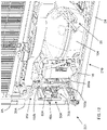
Figure 1 shows a rear perspective view of a refrigeration appliance according to a preferred embodiment of the invention; -
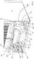
Figure 2 shows an enlarged detail ofFigure 1 ; -
Figure 3 shows the detail ofFigure 2 from another point of view; -
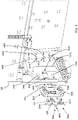
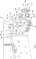
Figure 4 shows a detail ofFigure 2 in a pre-assembled position; -
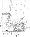
Figure 5 shows the detail ofFigure 4 in a first assembled position; -
Figure 6 shows a plan view ofFigure 5 ; -
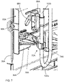
Figure 7 shows an enlarged view of a detail ofFigure 6 in a final assembled position; -
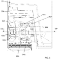
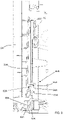
Figure 8 is a cross section view along line VII°-VII° offigure 6 ; -
Figure 8A shows the section offigure 8 in a disengaging position; -
Figure 9 shows a detail ofFigure 3 in a pre-assembled position; -
Figure 10 shows the detail ofFigure 9 in a first assembled position; -
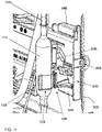
Figure 11 shows an enlarged view of a detail ofFigure 10 in a final assembled position; -
Figure 12 shows the enlarged detail ofFigure 2 of a refrigeration appliance according to a further preferred embodiment of the invention; -
Figure 13 shows the detail ofFigure 12 from another point of view; -
Figure 14 shows a detail ofFigure 12 in a pre-assembled position; -
Figure 15 shows a detail ofFigure 13 in a pre-assembled position. - The refrigeration appliance according to the present invention has proved to be particularly advantageous when refers to a refrigeration appliance for domestic use. It should in any case be underlined that the present invention is not limited to this particular embodiment. On the contrary, the present invention conveniently refers to any refrigeration appliance being provided with a working chamber wherein components for the functioning of the refrigeration appliance are arranged.
- Referring to
Figure 1 a refrigeration appliance, or refrigerator, in the form of a domestic stand-alone refrigerator is shown, indicated generally as 1. Although the detailed description that follows concerns a domestic stand-alone refrigerator 1, the refrigeration appliance can be embodied by refrigeration appliances other than a domestic refrigerator. - Furthermore, the embodiments described in detail below refers to a refrigerator comprising one fresh food compartment. However, the refrigerator according to the invention can have any desired configuration, for example a refrigerator comprising only one freezer compartment or a bottom mount refrigerator, i.e. of the type including a freezer compartment disposed vertically below a fresh food compartment, or a top mount refrigerator wherein a freezer compartment is disposed vertically above a fresh food compartment.
- Furthermore, while the present application is described with reference to a stand-alone refrigerator it has to be noted that also a built-in solution may be contemplated.
- The
refrigerator 1 preferably comprises a fresh food compartment, not shown in the figures. Therefrigerator 1 preferably comprises anouter cabinet 2 and an inner liner (not shown), internally received in theouter cabinet 2, that preferably defines said fresh food compartment. - A
door 15 is preferably pivotally mounted to theouter cabinet 2 and is movable between an open position and a closed position to cover the fresh food compartment. - A
refrigeration system 100 is preferably provided to cool the fresh food compartment, more preferably therefrigeration system 100 is apt to cool down air which is circulated inside the fresh food compartment. - The
refrigeration system 100 preferably comprises components configured to generate said cooling air flow. Therefrigeration system 100 preferably comprises aclosed refrigerating circuit 102 filled with a suitable refrigerant, for example R12 or R134a. Therefrigeration system 100 preferably comprises an electric motor-drivencompressor 104, acondenser heat exchanger 106, a pressure device such as a capillary tube or a thermostatic valve and an evaporator. A fan is also preferably used to circulate the cooled air inside the fresh food compartment. The refrigeratingcircuit 102 is preferably embodied as a plurality tubular-shaped circulatingtube portions - A
filter 114 is also preferably arranged along theclosed refrigerating circuit 102 to filter impurities that may be present in the refrigerant. Thefilter 114 is preferably arranged between acondenser heat exchanger 106 and the pressure device. - The
filter 114 is preferably embodied as a tubular-shaped component. - An
electrical cable 116 is provided to supply electrical power to theelectric motor 104a of thecompressor 104. According to the preferred embodiment shown inFigures 1 to 11 , theelectric motor 104a is afixed speed motor 104a. Theouter cabinet 2 is preferably parallelepiped-shaped and preferably comprisesside walls lateral side walls rear side wall 2C and atop side wall 2D. - In its standing working position,
lateral side walls rear side wall 2C are preferably aligned to a vertical direction. - Some of the above-described components of the
refrigeration system 100 are preferably arranged in a workingchamber 20 of therefrigerator 1. - The working
chamber 20 is preferably arranged at the back side of therefrigerator 1 and preferably at a bottom part of therear side wall 2C. - The working
chamber 20 is preferably open towards the outside so that dissipation of heat produced by components inside the workingchamber 20 is enhanced, in particular heat produced by thecompressor 104 and/or theelectric motor 104a. Furthermore, workingchamber 20 can be conveniently accessible in case of maintenance. - The working
chamber 20 is preferably defined by one ormore chamber walls - Two
lateral chamber walls chamber 20 and arear chamber wall 22 preferably delimits the workingchamber 20 in the back-to-front direction. - The
rear chamber wall 22 is preferably embodied as a shapedpanel 22 used to also thermally insulating the workingchamber 20 with respect to the fresh food compartment. - The
lateral chamber walls chamber 20 are preferably constituted by respective separated lower parts of thelateral side walls outer cabinet 2. - In a preferred embodiment, the
lateral chamber walls lateral side walls - The base supports 30A, 30B advantageously support the
refrigerator 1 when the latest is positioned in its standing working position. - In different preferred embodiments, the lateral chamber walls of the working chamber may correspond to the lower part of the lateral side walls of the outer cabinet or, in other words, the lateral chamber walls of the working chamber are not separated parts from the lateral side walls of the outer cabinet.
- Furthermore, the base supports 30A, 30B are opportunely configured to receive a supporting
element 24 which is preferably arranged in the lower part of the workingchamber 20, preferably to support components inside the workingchamber 20. More preferably the supportingelement 24 supports thecompressor 104 which is preferably fixed withscrews 26 to the supportingelement 24. According to an aspect of the invention, a holdingdevice base support component circuit 102 and/or anelectrical cable 116, as better described later. - In the preferred embodiment illustrated herein, there are provided two
holding devices right holding device 50A removably connected to the right supports 30A and aleft holding device 50B removably connected to theleft support 30B. - The two
holding devices - Hereinafter, the description will be firstly focused on the
right holding device 50A. - The
right holding device 50A preferably comprises an approximately parallelepiped-shaped body, preferably made of plastic. - As said above, the
right holding device 50A is removably connected to theright support 30A and more preferably theright holding device 50A is removably connected in a sliding way to theright support 30A. - The
right holding device 50A is thus preferably displaceable in at least an extracted position, as illustrated for example inFigure 4 , and an inserted or working position, as illustrated for example inFigures 2 ,5 and6 . - The extracted position preferably represents either a possible pre-assembled position of the holding
device 50A during assembling of therefrigerator 1 or a position useful in case of maintenance operations. - The
right support 30A preferably comprises two slitsurfaces device 50A comprises two respective protrudingribs right support 30A. - The
right holding device 50A is therefore easily moved for insertion into, or removal from, the workingchamber 20 andribs - One or
more retaining devices device 50A in the working position. - A
first retaining device 40A preferably comprises one ormore recesses right support 30A which engage with retainingsurfaces right holding device 50A when the holdingdevice 50A in placed in the working position. Therecesses ribs right support 30A. The reinforcingribs right support 30A at an innermost position inside the workingchamber 20. The retaining surfaces 55A, 56A of theright holding device 50A are preferably realized on a head portion of the holdingdevice 50A. A second retaining/fixing device 46A preferably comprises a screw (not shown) insertable in ahole 48A of theright holding device 50A and engageable in ahole 49A of theright support 30A. - The
hole 48A of theright holding device 50A is preferably realized on theright support 30A at an outermost position of the workingchamber 20. The screw can be therefore easily screwed and unscrewed, during assembling steps and/or maintenance operations. - A snap-in
device 60A if further preferably provided to maintain theholding device 50A in a stable position with respect to theright support 30A and to allow a quick disconnection of the holdingdevice 50A from theright support 30A, as better described below. - The snap-in
device 60A, better shown inFigure 8 , preferably comprises atooth element 62A associated to theright support 30A and arespective retaining surface 64A associated to theholding device 50A. Thetooth element 62A engages the retainingsurface 64A when the holding device 50 is in the working position. - The retaining
surface 64A is preferably defined in abridge portion 66A of the holdingdevice 50A. Thebridge portion 66A preferably has aslot 68A which preferably opens towards the open side of the workingchamber 20. Advantageously, disengagement of thetooth element 62A from the retainingsurface 64A may be carried out by inserting a disengaging tool T thorough theslot 68A, as illustrated inFigure 8A , which partially deforms thebridge portion 66A so that the retainingsurface 64A is sufficiently separated from thetooth element 62A allowing its disengagement. - Advantageously, the
tooth element 62A is easily reachable from the open side of the workingchamber 20. Assembling or disassembling of the holding device 50 thus advantageously requires only an external handling by an operator. - In a different preferred embodiment, the snap-in device may comprise a tooth element associated to the holding device and a respective retaining surface associated to right support.
- According to the preferred embodiment described above, the two
retaining devices device 60A enhance theholding device 50A to be safely maintained in the working position and/or to be easily removed from the workingchamber 20. - In different preferred embodiments, nevertheless, only one of the two retaining devices and/or only the snap-in device may be contemplated.
- According to another aspect of the invention, the holding device 50 preferably comprises at least one protruding
element component circuit 102 and/or anelectrical cable 116. - In a preferred embodiment, the protruding
element 70A comprises amovable bracket 70A apt to be positioned between a rest position, as shown for example inFigures 4 ,5 and6 , and an operating position, as shown for example inFigures 2 and7 . - In the operating position the
movable bracket 70A preferably holds at least one component of the refrigeratingcircuit 102 and/or an electrical cable. - In the preferred embodiment illustrated in the Figures, the
movable bracket 70A preferably holds atube portion 102a of the refrigeratingcircuit 102. - In the rest position, the
movable bracket 70A does not hold any components or electrical cables. - Preferably, the
movable bracket 70A is embodied as a rotatable bracket. Therotatable bracket 70A is preferably hinged to the holding device 50 at an end thereof. Therotatable bracket 70A is therefore advantageously rotatable to be at least positioned in said rest and operating positions. - Preferably, in the rest position the
rotatable bracket 70A is arranged parallel to theright support 30A, i.e. substantially in vertical position. In the operating position therotatable bracket 70A is inclined with respect to theright support 30A, preferably is perpendicular with respect to theright support 30A, i.e. substantially arranged in horizontal position. - In general, inclination of the
movable bracket 70A in the operating position depends on the final inclination of component held by themovable bracket 70A. Themovable bracket 70A preferably comprises agripping portion 72A apt to surround thetube portion 102a. - The gripping
portion 72A is preferably configured to match the outer shape of the component to be held. More preferably, the grippingportion 72A is configured to match the tubular shape of the component. - The gripping
portion 72A preferably comprises a clip, more preferably a snap-in open clip. - The clip preferably has a substantially circular shape with an
aperture 74A (Figure 7 ) through which thetube portion 102a is received when themovable bracket 70A is moved from the resting position to the operating position. - The
clip 72A is also preferably at least partially flexible so that thetube portion 102a is firmly held therein. - In a further preferred aspect, the at least one protruding
element 90A comprises a plurality of tongues, more preferably elastic tongues, apt to define at least oneseat 92A to hold, or temporarily hold, at least one component of the refrigeratingcircuit 102 and/or anelectrical cable 116. - Preferably, according to the embodiment illustrated in the Figures, the
seats 92A receive the electricalpower supply cable 116 of theelectric motor 104a of thecompressor 104, more preferably theseats 92A temporarily receive said electricalpower supply cable 116, as better described later. - More preferably, the
seats 92A are opportunely arranged so that the final portion of the electricalpower supply cable 116 may be wound as a spiral on the holdingdevice 50A, as illustrated inFigures 4 to 6 . - Preferably, there are further provided two
fixing points 94A for the electricalpower supply cable 116. The twofixing points 94A preferably comprise a retaining tab with an aperture through which the electricalpower supply cable 116 may be inserted to be the firmly held therein. - Hereinafter, a preferred use of the
right holding device 50A is described. - The holding
device 50A is firstly advantageously used during assembling steps in manufacturing of therefrigerator 1. -
Figure 4 shows a pre-assembled position of the holdingdevice 50A during manufacturing of therefrigerator 1 wherein components of therefrigeration system 100 are not yet completely assembled/connected therebetween. - In particular, the
tube portions circuit 102 are not connected one to the other and also thepower supply cable 116 is not electrically connected to themotor 104a of thecompressor 104. According to the preferred step of the assembling, thepower supply cable 116 is firstly preferably wound as a spiral on the holdingdevice 50A, as shown inFigure 4 . More preferably, thepower supply cable 116 is inserted inrespective seats 92A and fixingpoints 94A of the holdingdevice 50A. - At the same time, the
rotatable bracket 70A is displaced in the rest position, i.e. preferably in vertical position. - The holding
device 50A is then inserted, through sliding, into the workingchamber 20 up to its final working position, as shown inFigures 5 and6 . - The snap-in
device 60A acts to maintain theholding device 50A in stable working position with thetooth element 62A of theright support 30A that abuts the retainingsurface 64A of the holdingdevice 50A. - In this working position, also recesses 41A, 42A of the
right support 30A preferably engage with retainingsurfaces right holding device 50A. - Finally, a screw is inserted/screwed in the
hole 49A of theright support 30A to fix theright holding device 50A to theright support 30A. - The following steps of the assembling further preferably comprises:
- unwinding the final portion of the
power supply cable 116 fromseats 92A of theright holding device 50A and connection of thepower supply cable 116 to theelectric motor 104a of thecompressor 104, as visible inFigure 2 ; - rotating the
rotatable bracket 70A from its rest vertical position to the operating position, preferably the horizontal position, so that the gripping portion/clip 72A of therotatable bracket 70A surrounds and grips thetube portion 102a of the refrigeratingcircuit 102, as shown inFigure 7 . - From this position, the
tube portions circuit 102 can be connected therebetween, preferably through welding. - The
rotatable bracket 70A, advantageously, in its operating position precisely holds thetube portion 102c inside the workingchamber 20. - Furthermore, advantageously, the
tube portion 102c is kept in position inside the workingchamber 20 thus avoiding the contact with other components. - From the description above, it is clear that the final portion of the
power supply cable 116 has been temporarily held by theseats 92A of theright holding device 50A during assembling. Thepower supply cable 116 is also held in position at the twofixing points 94A. - Advantageously, the
right holding device 50A of the invention optimizes assembling operations and simplifies the manufacturing process of therefrigerator 1. - Furthermore, preferably, in case of maintenance simple disassembling operations are carried out, for example rotation of the
rotatable bracket 70A from its operating position to the rest vertical position, unscrewing of the screw from therespective hole 49A, disengagement of theright holding device 50A by acting on the snap-indevice 60A with the disengaging tool T and extraction of theright holding device 50A from the workingchamber 20 through sliding. - Still advantageously, during assembly of the holding
device 50A into the workingchamber 20 or disassembly of the holdingdevice 50A from the workingchamber 20 therotatable bracket 70A may be positioned in rest vertical position so that it is not cumbersome. - Hereinafter, the
left holding device 50B will be described, being in mind that it has substantially the same shape and functionality of theright holding device 50A. - The
left holding device 50B preferably comprises an approximately parallelepiped-shaped body, preferably made of plastic. - The
left holding device 50B is removably connected to theleft support 30B and more preferably theleft holding device 50B is removably connected in a sliding way to theleft support 30B. - The
left holding device 50B is thus preferably displaceable in at least an extracted position, as illustrated for example inFigure 9 , and an inserted or working position, as illustrated for example inFigures 3 and10 . - The extracted position preferably represents either a possible pre-assembled position of the holding
device 50B during assembling of therefrigerator 1 or a position useful in case of maintenance operations. - The
left support 30B preferably comprises two slitsurfaces device 50B comprises two respective protrudingribs left support 30B. - The
left holding device 50B is therefore easily moved for insertion into, or removal from, the workingchamber 20 andribs - One or
more retaining devices device 50B in the working position. - A
first retaining device 40B preferably comprises one ormore recesses 42B provided at theleft support 30B which engage with retainingsurfaces left holding device 50B when the holdingdevice 50B in placed in the working position. Therecesses 42B are preferably defined at reinforcingribs left support 30B. The reinforcingribs left support 30B at an innermost position inside the workingchamber 20. The retaining surfaces 55B, 56B of theleft holding device 50B are preferably realized on a head portion of the holdingdevice 50B. - A second retaining/
fixing device 46B preferably comprises a screw (not shown) insertable in ahole 48B of theleft holding device 50B and engageable in ahole 49B of theleft support 30B. - The
hole 48B of theleft holding device 50B is preferably realized on theleft support 30B at an outermost position of the workingchamber 20. The screw can be therefore easily screwed and unscrewed, during assembling steps and/or maintenance operations. - A snap-in
device 60B if further preferably provided to maintain theholding device 50B in a stable position with respect to theleft support 30B and to allow a quick disconnection of the holdingdevice 50B from theleft support 30B. - The snap-in
device 60B substantially corresponds to the snap-indevice 60A illustrated and described with respect to theright holding device 50A and therefore not described in detail. - According to the preferred embodiment described above, the two retaining
devices device 60B enhance theleft holding device 50B to be safely maintained in the working position and/or to be easily removed from the workingchamber 20. - In different preferred embodiments, nevertheless, only one of the two retaining devices and/or only the snap-in device may be contemplated.
- According to another aspect of the invention, the holding device 50 preferably comprises at least one protruding
element 70B, 90B apt to hold, or temporarily hold, at least onecomponent 114 of the refrigeratingcircuit 102. - In a preferred embodiment, the protruding
element 70B comprises amovable bracket 70B apt to be positioned between a rest position, as shown for example inFigures 9 and10 , and an operating position, as shown for example inFigures 3 and11 . - In the operating position the
movable bracket 70B preferably holds at least onecomponent 114 of the refrigeratingcircuit 102 and/or an electrical cable. - In the preferred embodiment illustrated in the Figures, the
movable bracket 70B preferably holds thefilter 114 of the refrigeratingcircuit 102. - In the rest position, the
movable bracket 70B does not hold any components or electrical cables. - Preferably, the
movable bracket 70B is embodied as a rotatable bracket. Therotatable bracket 70B is preferably hinged to theholding device 50B at an end thereof. Therotatable bracket 70B is therefore advantageously rotatable to be at least positioned in said rest and operating positions. - Preferably, in the rest position the
rotatable bracket 70B is arranged parallel to theleft support 30B, i.e. substantially in vertical position. In the operating position therotatable bracket 70B is inclined with respect to theleft support 30B, preferably is perpendicular with respect to theleft support 30B, i.e. substantially arranged in horizontal position. - In general, inclination of the
movable bracket 70B in the operating position depends on the final inclination of component held by themovable bracket 70B. Themovable bracket 70B preferably comprises agripping portion 72B apt to surround thefilter 114. - The gripping
portion 72B is preferably configured to match the outer shape of the component to be held. More preferably, the grippingportion 72B is configured to match the tubular shape of the component. - The gripping
portion 72B preferably comprises a clip, more preferably a snap-in open clip. - The
clip 72B preferably has a substantially circular shape with anaperture 74B (Figure 11 ) through which thefilter 114 is received when themovable bracket 70B is moved from the resting position to the operating position. - The
clip 72B is also preferably at least partially flexible so that thefilter 114 is firmly held therein. - In a further preferred aspect, the at least one protruding element comprises a plurality of tongues, more preferably elastic tongues, apt to define at least one
seat 92B to hold, or temporarily hold, at least one component of the refrigeratingcircuit 102 and/or an electrical cable. - According to the embodiment illustrated in the
Figures 9 to 11 , theseats 92B are not eventually used. In different embodiments, as illustrated for example in the preferred embodiment shown inFigures 12 to 15 , theseats 92B are preferably configured to receive anelectrical cable 216. - More preferably, the
seats 92B are opportunely arranged to temporarily hold thecable 216 during assembling, as better described later. - Preferably, there are further provided two
fixing points 94B for an electrical cable. The twofixing points 94B preferably comprise a retaining tab with an aperture through which the cable may be eventually inserted to be the firmly held therein. - Hereinafter, a preferred use of the
left holding device 50B is described. - The holding
device 50B is firstly advantageously used during assembling steps in manufacturing of therefrigerator 1. -
Figure 9 shows a pre-assembled position of the holdingdevice 50B during manufacturing of therefrigerator 1 wherein components of therefrigeration system 100 are not yet completely assembled/connected therebetween. - In particular, a
tube portion 102c and atemporary cap 114a is initially arranged inside the workingchamber 20 while thefilter 114 is not yet assembled. According to the preferred step of the assembling, theleft holding device 50B does not held any component and at the same time therotatable bracket 70B is displaced in the rest position, i.e. preferably in vertical position. - The holding
device 50B is then inserted, through sliding, into the workingchamber 20 up to its final working position, as shown inFigure 10 . - The snap-in
device 60B acts to maintain theholding device 50B in stable working position. - In this working position, also recesses 42B of the
left support 30B preferably engage with retainingsurfaces left holding device 50B. - Finally, a screw is inserted/screwed in the
hole 49B of theleft support 30B to fix theleft holding device 50B to theleft support 30B. - The following step of the assembling preferably comprises the removal of the
temporary cap 114a from thetube portion 102c and the connection of thefilter 114. The following step further preferably comprises rotating therotatable bracket 70B from its rest vertical position to the operating position, preferably the horizontal position, so that the grippingportion 72B of therotatable bracket 70B surrounds and grips thefilter 114, as shown inFigures 3 and11 . - The
rotatable bracket 70B, advantageously, in its operating position precisely holds thefilter 114 inside the workingchamber 20. - Furthermore, advantageously, the
filter 114 is kept in position inside the workingchamber 20 thus avoiding the contact with other components. - Advantageously, the
left holding device 50B of the invention optimizes assembling operations and simplifies the manufacturing process of the refrigerator. - Furthermore, preferably, in case of maintenance simple disassembling operations are carried out, for example rotation of the
rotatable bracket 70B from its operating position to the rest vertical position, unscrewing of the screw from therespective hole 49B, disengagement of theleft holding device 50B by acting on the snap-indevice 60B with a disengaging tool and extraction of theleft holding device 50B through sliding. - Still advantageously, during assembly of the holding
device 50B into the workingchamber 20 or disassembly of the holdingdevice 50B from the workingchamber 20 therotatable bracket 70B may be positioned in rest vertical position so that it is not cumbersome. -
Figures 12 to 15 refer to arefrigeration appliance 201 according to a further preferred embodiment of the invention. - In the drawings, corresponding characteristics and/or components compared to previous preferred embodiment are identified by the same reference numbers. The
refrigeration appliance 201 of this preferred embodiment differs from therefrigeration appliance 1 previously described mainly in the different arrangement and/or type of components of refrigeratingcircuit 202 and/or electrical cables of therefrigeration system 210. - A first difference is that the
compressor 104 is driven through a variable speedelectric motor 204a (Figure 12 ) rather than a fixed speed electric motor, more preferably through an inverter device. Theelectrical cable 116, therefore, supplies electrical power to the variable speedelectric motor 204a. - A second difference is that the
refrigeration system 210 further comprises a divertingvalve 214 arranged in the refrigeratingcircuit 202 and received in the workingchamber 20. A diverting valve is preferably used when the refrigerant in a refrigerating circuit system needs to be diverted in two or more different directions. - An
electrical cable 216 preferably supplies electrical power to the divertingvalve 214. - All other components of the
refrigeration appliance 201 preferably correspond to the components previously described, in particular the right and left holdingdevices - Hereinafter, a preferred use of the
right holding device 50A is described. - The holding
device 50A is firstly advantageously used during assembling steps in manufacturing of therefrigerator 201. -
Figure 14 shows a pre-assembled position of the holdingdevice 50A during manufacturing of therefrigerator 201 wherein components of therefrigeration system 210 are not yet completely assembled/connected therebetween. - In particular, the
tube portions circuit 202 are not connected one to the other and also thepower supply cable 116 is not electrically connected to themotor 204a of thecompressor 104. According to the preferred step of the assembling, thepower supply cable 116 is firstly preferably wound as a spiral on the holdingdevice 50A, as shown inFigure 14 . More preferably, thepower supply cable 116 is inserted inrespective seats 92A and fixingpoints 94A of the holdingdevice 50A. - At the same time, the
rotatable bracket 70A is displaced in the rest position, i.e. preferably in vertical position. - The holding
device 50A is then inserted, through sliding, into the workingchamber 20 up to its final working position, as shown inFigure 12 . - The snap-in
device 60A acts to maintain theholding device 50A in stable working position inside the workingchamber 20. - In this working position, also recesses 41A, 42A of the
right support 30A preferably engage with retainingsurfaces right holding device 50A. - Finally, a screw is inserted/screwed in the
hole 49A of theright support 30A to fix theright holding device 50A to theright support 30A. - The following steps of the assembling further preferably comprises:
- unwinding the final portion of the
power supply cable 116 fromseats 92A of theright holding device 50A and connection of thepower supply cable 116 to theelectric motor 204a of thecompressor 104, as visible inFigure 12 ; - rotating the
rotatable bracket 70A from its rest vertical position to the operating position, preferably the horizontal position, so that the gripping portion/clip 72A of therotatable bracket 70A surrounds and grips thetube portion 102a of the refrigeratingcircuit 202, as shown inFigure 12 . - From this position, the
tube portions circuit 202 can be connected therebetween, preferably through welding. - Hereinafter, a preferred use of the
left holding device 50B is described. - The holding
device 50B is firstly advantageously used during assembling steps in manufacturing of therefrigerator 1. -
Figure 15 shows a pre-assembled position of the holdingdevice 50B during manufacturing of therefrigerator 201 wherein components of therefrigeration system 210 are not yet completely assembled/connected therebetween. - In particular, a
tube portion 102c and atemporary cap 114a is initially arranged inside the workingchamber 20 while thefilter 114 is not yet assembled. Furthermore, thepower supply cable 216 is not electrically connected to the to the divertingvalve 214. - According to the preferred step of the assembling, the
left holding device 50B does not held any component and at the same time therotatable bracket 70B is displaced in the rest position, i.e. preferably in vertical position. - According to the preferred step of the assembling, the
power supply cable 216 is firstly preferably wound as a spiral on theright holding device 50B, as shown inFigure 15 . More preferably, thepower supply cable 216 is inserted inrespective seats 92B and fixingpoints 94B of the holdingdevice 50B. - At the same time, the
rotatable bracket 70B is displaced in the rest position, i.e. preferably in vertical position. - The holding
device 50B is then inserted, through sliding, into the workingchamber 20 up to its final working position, as shown inFigure 13 . - The snap-in
device 60B acts to maintain theholding device 50B in stable working position inside the workingchamber 20. - In this working position, also recesses of the
left support 30B preferably engage with retainingsurfaces left holding device 50B. - Finally, a screw is inserted/screwed in the
hole 49B of theleft support 30B to fix theleft holding device 50B to theleft support 30B. - The following steps of the assembling further preferably comprises:
- unwinding the final portion of the
power supply cable 216 fromseats 92B of theleft holding device 50B and connection of thepower supply cable 216 to the to the divertingvalve 214, as visible inFigure 13 ; - removing the
temporary cap 114a from thetube portion 102c and the connection of thefilter 114; - rotating the
rotatable bracket 70B from its rest vertical position to the operating position, preferably the horizontal position, so that the grippingportion 72B of therotatable bracket 70B surrounds and grips thefilter 114, as shown inFigure 13 . - The holding
devices - From the above descriptions, furthermore, it is clear that same holding devices can be used for different refrigeration appliance models, for example refrigeration appliances with different refrigeration systems, thus reducing manufacturing costs and number of components required.
- While the present invention has been described with reference to the particular components of the refrigerating circuit such as tubes and filter, it should be noted that the present invention is not limited to said specific components and other components may be advantageously held, or temporarily held, by the holding device according to the invention, for example valves, capillary tubes, fluxmeters, etc. Components are preferably tubularly-shaped.
- Analogously, while the present invention has been described with reference to electrical cables supplying electrical power to the compressor motor or to a to the diverting valve, it should be noted that the present invention is not limited to power supply cable and other electrical cable may be advantageously held, or temporarily held, by the holding device according to the invention, such as data communication electrical cables, for example cables for data detected from sensors.
- It has thus been shown that the present invention allows all the set objects to be achieved. In particular, the refrigeration appliance of the invention makes it possible to optimize assembling operations compared to known techniques. While the present invention has been described with reference to the particular embodiments shown in the figures, it should be noted that the present invention is not limited to the specific embodiments illustrated and described herein; on the contrary, further variants of the embodiments described herein fall within the scope of the present invention, which is defined in the claims.
Claims (16)
- A refrigeration appliance (1; 201) comprising:- at least one compartment for the storage of products to be cooled and an outer cabinet (2) enclosing said at least one compartment;- a refrigeration system (100; 210) configured to cool said at least one compartment and comprising a closed refrigerating circuit (102; 202) filled with a refrigerant;- a working chamber (20) apt to receive at least one component (102a, 114) of said refrigerating circuit (102; 202) and/or at least one electrical cable (116; 216) for the functioning of said appliance (1; 201);- at least one chamber wall (30A, 30B) at least partially delimiting said working chamber (20);wherein said appliance (1; 201) comprises a holding device (50A, 50B) apt to be removably connected to said at least one chamber wall (30A, 30B) and apt to at least temporarily hold said at least one component (102a, 114) of said refrigerating circuit (102; 202) and/or said at least one electrical cable (116; 216).
- An appliance (1; 201) according to claim 1, wherein said holding device (50A, 50B) is slidingly associated to said at least one chamber wall (30A, 30B).
- An appliance (1; 201) according to claim 2, wherein said at least one chamber wall (30A, 30B) comprises at least one slit surface (32A, 34A, 32B, 34B) and said holding device (50A, 50B) comprises at least one respective protruding rib (52A, 54A, 52B, 54B) apt to slidingly engage with said one slit surface (32A, 34A, 32B, 34B) or said holding device comprises at least one slit surface and said wall chamber comprises at least one respective protruding rib apt to slidingly engage with said one slit surface.
- An appliance (1; 201) according to any of the preceding claims, wherein said appliance (1; 201) comprises a snap-in device (60A, 60B) apt to maintain said holding device (50A, 50B) in a stable position with respect to said at least one chamber wall (30A, 30B).
- An appliance (1; 201) according to claim 4, wherein said snap-in device (60A, 60B) comprises at least one tooth element (62A) associated to said at least one chamber wall (30A, 30B) and at least one respective retaining surface (64A) associated to said holding device (50A, 50B) or at least one tooth element associated to said holding device and at least one respective retaining surface associated to said at least one chamber wall.
- An appliance (1; 201) according to claim 5, wherein said one tooth element (62A) and/or said retaining surface (64A) are arranged inside said working chamber (20) in a position so as to be reachable with a disengaging tool (T) for disengaging said one tooth element (62A) from said retaining surface (64A).
- An appliance (1; 201) according to any of the preceding claims, wherein said at least one component (102a, 114) of said refrigerating circuit (102; 202) comprises a tubular-shaped component, preferably a circulating tube (102a) for said refrigerant or a valve or a capillary tube or a fluxmeter or a filter (114).
- An appliance (1; 201) according to any of the preceding claims, wherein said holding device (50A, 50B) comprises at least one protruding element (70A, 90A, 70B, 90B) apt to at least temporarily hold said at least one component (102a, 114) of said refrigerating circuit (102; 202) and/or said at least one electrical cable (116; 216).
- An appliance (1; 201) according to claim 8, wherein said at least one protruding element (70A, 70B) comprises a movable bracket (70A, 70B) apt to be positioned in a rest position and in an operating position, wherein in said operating position said movable bracket holds said at least one component (102a, 114) or said at least one electrical cable (116; 216).
- An appliance (1; 201) according to claim 9, wherein said movable bracket (70A, 70B) is a rotatable bracket apt to be rotated between said operating position and said rest position.
- An appliance (1; 201) according to claim 10, wherein in said rest position said rotatable bracket (70A, 70B) is arranged parallel to said at least one chamber wall (30A, 30B) and in said operating position said rotatable bracket (70A, 70B) is inclined with respect to said at least one chamber wall (30A, 30B), preferably is perpendicular with respect to said at least one chamber wall (30A, 30B).
- An appliance (1; 201) according to any of the claims 9 to 11, wherein said movable bracket (70A, 70B) comprises a gripping portion (72A, 72B) apt to surround said at least one component (102a, 114) or said at least one electrical cable (116; 216), preferably said gripping portion (72A, 72B) comprises a clip, more preferably a snap-in open clip.
- An appliance (1; 201) according to any of the claims 8 to 12, wherein said at least one protruding element (90A, 90B) comprises a plurality of tongues, more preferably elastic tongues, apt to define at least one seat (92A, 92B) to hold, or temporarily hold, said at least one component (102a, 114) or said at least one electrical cable (116; 216).
- An appliance (1; 201) according to any of the preceding claims, wherein it further comprises a retaining device (40A, 46A, 40B, 46B) apt to keep said holding device (50A, 50B) in position inside said working chamber (20).
- An appliance (1; 201) according to claim 14, wherein said retaining device (40A, 40B) comprises one or more recesses (41A, 42A, 42B) provided at said at least one chamber wall (30A, 30B) and one or more corresponding retaining surfaces (55A, 56A, 55B, 56B) provided at said holding device (50A, 50B), preferably said one or more recesses (41A, 42A, 42B) being defined at reinforcing ribs (43A, 44A, 43B, 44B) of said at least one chamber wall (30A, 30B).
- An appliance (1; 201) according to claim 14 or 15, wherein said retaining device (46A, 46B) comprises a screw insertable in a hole (48A, 48B) of said holding device (50A, 50B) and engageable in a hole (49A, 49B) of said at least one chamber wall (30A, 30B).
Priority Applications (1)
| Application Number | Priority Date | Filing Date | Title |
|---|---|---|---|
| EP21184698.5A EP4116647A1 (en) | 2021-07-09 | 2021-07-09 | Refrigeration appliance |
Applications Claiming Priority (1)
| Application Number | Priority Date | Filing Date | Title |
|---|---|---|---|
| EP21184698.5A EP4116647A1 (en) | 2021-07-09 | 2021-07-09 | Refrigeration appliance |
Publications (1)
| Publication Number | Publication Date |
|---|---|
| EP4116647A1 true EP4116647A1 (en) | 2023-01-11 |
Family
ID=76859457
Family Applications (1)
| Application Number | Title | Priority Date | Filing Date |
|---|---|---|---|
| EP21184698.5A Pending EP4116647A1 (en) | 2021-07-09 | 2021-07-09 | Refrigeration appliance |
Country Status (1)
| Country | Link |
|---|---|
| EP (1) | EP4116647A1 (en) |
Citations (6)
| Publication number | Priority date | Publication date | Assignee | Title |
|---|---|---|---|---|
| ES2316178T3 (en) * | 1998-05-14 | 2009-04-01 | Bsh Bosch Und Siemens Hausgerate Gmbh | FRIDGE. |
| KR101059812B1 (en) * | 2004-04-09 | 2011-08-26 | 삼성전자주식회사 | Refrigerator |
| WO2012113630A2 (en) * | 2011-02-23 | 2012-08-30 | BSH Bosch und Siemens Hausgeräte GmbH | Electric domestic appliance |
| DE102012222845A1 (en) * | 2012-12-12 | 2014-06-12 | BSH Bosch und Siemens Hausgeräte GmbH | Cooling apparatus i.e. household cooling apparatus, has holder including multiple recesses, where each recess is inserted with one outgoing cable, and comprises individual closure that retains cable in recess |
| DE102017221904A1 (en) * | 2017-12-05 | 2019-06-06 | BSH Hausgeräte GmbH | Appliances device |
| KR101994688B1 (en) * | 2017-04-03 | 2019-07-01 | 엘지전자 주식회사 | Refrigerator |
-
2021
- 2021-07-09 EP EP21184698.5A patent/EP4116647A1/en active Pending
Patent Citations (6)
| Publication number | Priority date | Publication date | Assignee | Title |
|---|---|---|---|---|
| ES2316178T3 (en) * | 1998-05-14 | 2009-04-01 | Bsh Bosch Und Siemens Hausgerate Gmbh | FRIDGE. |
| KR101059812B1 (en) * | 2004-04-09 | 2011-08-26 | 삼성전자주식회사 | Refrigerator |
| WO2012113630A2 (en) * | 2011-02-23 | 2012-08-30 | BSH Bosch und Siemens Hausgeräte GmbH | Electric domestic appliance |
| DE102012222845A1 (en) * | 2012-12-12 | 2014-06-12 | BSH Bosch und Siemens Hausgeräte GmbH | Cooling apparatus i.e. household cooling apparatus, has holder including multiple recesses, where each recess is inserted with one outgoing cable, and comprises individual closure that retains cable in recess |
| KR101994688B1 (en) * | 2017-04-03 | 2019-07-01 | 엘지전자 주식회사 | Refrigerator |
| DE102017221904A1 (en) * | 2017-12-05 | 2019-06-06 | BSH Hausgeräte GmbH | Appliances device |
Similar Documents
| Publication | Publication Date | Title |
|---|---|---|
| EP2198225B1 (en) | Refrigeration module and refrigeration system | |
| KR0168995B1 (en) | Freezer structure of the refrigerator | |
| KR100751119B1 (en) | Refrigerator | |
| EP1616138A1 (en) | Modular refrigeration unit | |
| KR200463568Y1 (en) | Refrigerator | |
| KR100423606B1 (en) | Fixed structure for guide rail on the vegetable room of kimchi refrigerator | |
| JP2005037120A (en) | Refrigerator | |
| WO2013000968A2 (en) | A refrigerator comprising a machine room | |
| JP2000310475A (en) | Cooler | |
| JP3653426B2 (en) | refrigerator | |
| JP4460971B2 (en) | Cooling storage | |
| JP2005037121A (en) | Refrigerator | |
| KR200332883Y1 (en) | cooling system withdrawal receiver for a refrigerator | |
| EP4116651A1 (en) | Refrigeration appliance | |
| EP4249834B1 (en) | Refrigerator | |
| KR100549076B1 (en) | Refrigerator | |
| KR200156603Y1 (en) | Showcase combinating an ice machine | |
| WO2020075242A1 (en) | Refrigerator | |
| EP4116646A1 (en) | Refrigeration appliance | |
| KR200379303Y1 (en) | Cooling structure | |
| KR0127768Y1 (en) | Electric box fixing structure of a refrigerator | |
| JP6609436B2 (en) | refrigerator | |
| KR20000005552U (en) | Fixing device for rear panel of refrigerator | |
| KR200248066Y1 (en) | A mini refrigerator having a separating type of control pannel assembly | |
| KR200217548Y1 (en) | Brackets for Fan Motors |
Legal Events
| Date | Code | Title | Description |
|---|---|---|---|
| PUAI | Public reference made under article 153(3) epc to a published international application that has entered the european phase |
Free format text: ORIGINAL CODE: 0009012 |
|
| STAA | Information on the status of an ep patent application or granted ep patent |
Free format text: STATUS: THE APPLICATION HAS BEEN PUBLISHED |
|
| AK | Designated contracting states |
Kind code of ref document: A1 Designated state(s): AL AT BE BG CH CY CZ DE DK EE ES FI FR GB GR HR HU IE IS IT LI LT LU LV MC MK MT NL NO PL PT RO RS SE SI SK SM TR |
|
| STAA | Information on the status of an ep patent application or granted ep patent |
Free format text: STATUS: REQUEST FOR EXAMINATION WAS MADE |
|
| 17P | Request for examination filed |
Effective date: 20230711 |
|
| RBV | Designated contracting states (corrected) |
Designated state(s): AL AT BE BG CH CY CZ DE DK EE ES FI FR GB GR HR HU IE IS IT LI LT LU LV MC MK MT NL NO PL PT RO RS SE SI SK SM TR |
|
| STAA | Information on the status of an ep patent application or granted ep patent |
Free format text: STATUS: EXAMINATION IS IN PROGRESS |
|
| 17Q | First examination report despatched |
Effective date: 20250312 |