EP4116643A1 - Refrigerant cycle apparatus and method for installing refrigerant cycle apparatus - Google Patents
Refrigerant cycle apparatus and method for installing refrigerant cycle apparatus Download PDFInfo
- Publication number
- EP4116643A1 EP4116643A1 EP20923458.2A EP20923458A EP4116643A1 EP 4116643 A1 EP4116643 A1 EP 4116643A1 EP 20923458 A EP20923458 A EP 20923458A EP 4116643 A1 EP4116643 A1 EP 4116643A1
- Authority
- EP
- European Patent Office
- Prior art keywords
- refrigerant
- heat source
- source unit
- cycle apparatus
- installation method
- Prior art date
- Legal status (The legal status is an assumption and is not a legal conclusion. Google has not performed a legal analysis and makes no representation as to the accuracy of the status listed.)
- Granted
Links
Images













Classifications
-
- F—MECHANICAL ENGINEERING; LIGHTING; HEATING; WEAPONS; BLASTING
- F25—REFRIGERATION OR COOLING; COMBINED HEATING AND REFRIGERATION SYSTEMS; HEAT PUMP SYSTEMS; MANUFACTURE OR STORAGE OF ICE; LIQUEFACTION SOLIDIFICATION OF GASES
- F25B—REFRIGERATION MACHINES, PLANTS OR SYSTEMS; COMBINED HEATING AND REFRIGERATION SYSTEMS; HEAT PUMP SYSTEMS
- F25B13/00—Compression machines, plants or systems, with reversible cycle
-
- F—MECHANICAL ENGINEERING; LIGHTING; HEATING; WEAPONS; BLASTING
- F25—REFRIGERATION OR COOLING; COMBINED HEATING AND REFRIGERATION SYSTEMS; HEAT PUMP SYSTEMS; MANUFACTURE OR STORAGE OF ICE; LIQUEFACTION SOLIDIFICATION OF GASES
- F25B—REFRIGERATION MACHINES, PLANTS OR SYSTEMS; COMBINED HEATING AND REFRIGERATION SYSTEMS; HEAT PUMP SYSTEMS
- F25B41/00—Fluid-circulation arrangements
- F25B41/40—Fluid line arrangements
-
- F—MECHANICAL ENGINEERING; LIGHTING; HEATING; WEAPONS; BLASTING
- F25—REFRIGERATION OR COOLING; COMBINED HEATING AND REFRIGERATION SYSTEMS; HEAT PUMP SYSTEMS; MANUFACTURE OR STORAGE OF ICE; LIQUEFACTION SOLIDIFICATION OF GASES
- F25B—REFRIGERATION MACHINES, PLANTS OR SYSTEMS; COMBINED HEATING AND REFRIGERATION SYSTEMS; HEAT PUMP SYSTEMS
- F25B45/00—Arrangements for charging or discharging refrigerant
-
- F—MECHANICAL ENGINEERING; LIGHTING; HEATING; WEAPONS; BLASTING
- F25—REFRIGERATION OR COOLING; COMBINED HEATING AND REFRIGERATION SYSTEMS; HEAT PUMP SYSTEMS; MANUFACTURE OR STORAGE OF ICE; LIQUEFACTION SOLIDIFICATION OF GASES
- F25B—REFRIGERATION MACHINES, PLANTS OR SYSTEMS; COMBINED HEATING AND REFRIGERATION SYSTEMS; HEAT PUMP SYSTEMS
- F25B49/00—Arrangement or mounting of control or safety devices
- F25B49/02—Arrangement or mounting of control or safety devices for compression type machines, plants or systems
-
- F—MECHANICAL ENGINEERING; LIGHTING; HEATING; WEAPONS; BLASTING
- F25—REFRIGERATION OR COOLING; COMBINED HEATING AND REFRIGERATION SYSTEMS; HEAT PUMP SYSTEMS; MANUFACTURE OR STORAGE OF ICE; LIQUEFACTION SOLIDIFICATION OF GASES
- F25B—REFRIGERATION MACHINES, PLANTS OR SYSTEMS; COMBINED HEATING AND REFRIGERATION SYSTEMS; HEAT PUMP SYSTEMS
- F25B2313/00—Compression machines, plants or systems with reversible cycle not otherwise provided for
- F25B2313/023—Compression machines, plants or systems with reversible cycle not otherwise provided for using multiple indoor units
- F25B2313/0233—Compression machines, plants or systems with reversible cycle not otherwise provided for using multiple indoor units in parallel arrangements
-
- F—MECHANICAL ENGINEERING; LIGHTING; HEATING; WEAPONS; BLASTING
- F25—REFRIGERATION OR COOLING; COMBINED HEATING AND REFRIGERATION SYSTEMS; HEAT PUMP SYSTEMS; MANUFACTURE OR STORAGE OF ICE; LIQUEFACTION SOLIDIFICATION OF GASES
- F25B—REFRIGERATION MACHINES, PLANTS OR SYSTEMS; COMBINED HEATING AND REFRIGERATION SYSTEMS; HEAT PUMP SYSTEMS
- F25B2345/00—Details for charging or discharging refrigerants; Service stations therefor
- F25B2345/002—Collecting refrigerant from a cycle
-
- F—MECHANICAL ENGINEERING; LIGHTING; HEATING; WEAPONS; BLASTING
- F25—REFRIGERATION OR COOLING; COMBINED HEATING AND REFRIGERATION SYSTEMS; HEAT PUMP SYSTEMS; MANUFACTURE OR STORAGE OF ICE; LIQUEFACTION SOLIDIFICATION OF GASES
- F25B—REFRIGERATION MACHINES, PLANTS OR SYSTEMS; COMBINED HEATING AND REFRIGERATION SYSTEMS; HEAT PUMP SYSTEMS
- F25B2400/00—Component parts or details not otherwise provided for in this subclass
- F25B2400/12—Inflammable refrigerants
Definitions
- the present disclosure relates to a refrigerant cycle apparatus and an installation method for the refrigerant cycle apparatus.
- Patent Literature 1 discloses an installation method for a refrigerant cycle apparatus. In this installation method, first, a refrigerant having non-flammability and a high global warming potential (GWP) is removed from a refrigerant cycle apparatus having been already installed. Next, a refrigerant having flammability and a low GWP is put into the refrigerant cycle apparatus.
- GWP global warming potential
- Non-flammable refrigerants currently on the market are being replaced by refrigerants having a small GWP but having flammability or toxicity (hereinafter, referred to as a "flammable refrigerant or the like") for the purpose of suppressing global warming. It is therefore expected that a refrigerant cycle apparatus using a flammable refrigerant or the like will become dominant among refrigerant cycle apparatuses manufactured in factories in the future. On the other hand, in some buildings, the use of a flammable refrigerant or the like may be deemed undesirable from the viewpoint of safety. In this way, there is still a need for both a non-flammable refrigerant and a flammable refrigerant or the like in the market.
- a refrigerant circuit of a refrigerant cycle apparatus to be shipped from a factory is evacuated or filled with air.
- the refrigerant cycle apparatus is transported to an installation site.
- the installed refrigerant cycle apparatus is filled with a desired refrigerant.
- the refrigerant cycle apparatus not accommodating a refrigerant could be damaged by transportation.
- a method includes installing a refrigerant cycle apparatus.
- the refrigerant cycle apparatus includes a first heat source unit, a utilization unit, and a connection pipe.
- the method includes a first refrigerant recovery step and a second refrigerant accommodation step.
- a first refrigerant is recovered from the first heat source unit.
- the first refrigerant has a first GWP and at least one of flammability or toxicity.
- a second refrigerant is accommodated in the first heat source unit.
- the second refrigerant is recovered and regenerated from an existing facility, has a second GWP, and has at least one of non-flammability or non-toxicity.
- the second refrigerant can be used in the refrigerant cycle apparatus configured using a new first heat source unit. Therefore, the refrigerant cycle apparatus of a new model can be installed in an environment that does not permit use of the first refrigerant having flammability or toxicity.
- a method according to a second aspect is the method according to the first aspect, in which the existing facility is an existing refrigerant cycle apparatus.
- the existing refrigerant cycle apparatus includes a second heat source unit, the utilization unit, and the connection pipe.
- the method further includes a second refrigerant recovery and regeneration step, a disconnection step, and a connection step.
- the second refrigerant recovery and regeneration step the second refrigerant is recovered from the existing facility, and the second refrigerant is regenerated.
- the disconnection step the second heat source unit is disconnected from the existing refrigerant cycle apparatus.
- the connection step the first heat source unit is connected to the connection pipe to configure the refrigerant cycle apparatus.
- the refrigerant cycle apparatus of a new model can be configured using a part of the existing refrigerant cycle apparatus. Therefore, costs of the refrigerant cycle apparatus can be reduced.
- a method according to a third aspect is the method according to the first aspect, in which the existing facility is a separate-system refrigerant cycle apparatus.
- the separate-system refrigerant cycle apparatus includes a constituent part different from the utilization unit and the connection pipe.
- the method further includes a second refrigerant recovery and regeneration step. In the second refrigerant recovery and regeneration step, the second refrigerant is recovered from the existing facility, and the second refrigerant is regenerated.
- the refrigerant cycle apparatus that is new as a whole can be installed using the first heat source unit of a new mode.
- a method according to a fourth aspect is the method according to the second or third aspect, in which in the second refrigerant recovery and regeneration step, the second refrigerant is accommodated in at least the refrigerant storage container.
- the second refrigerant is accommodated in the refrigerant storage container. It is therefore easy to know an amount of the recovered second refrigerant by the number of refrigerant storage containers used.
- a method according to a fifth aspect is the method according to any one of the second to fourth aspects, in which in the second refrigerant recovery and regeneration step, the second refrigerant is accommodated in at least the first heat source unit.
- the first heat source unit is used as a storage container for the second refrigerant. Therefore, since the number of refrigerant storage containers required for installing the refrigerant cycle apparatus can be reduced, an installation cost can be reduced.
- a method according to a sixth aspect is the method according to any one of the second to fifth aspects, in which in the second refrigerant recovery and regeneration step, at least one of second lubricating oil or water included in the second refrigerant is removed from the second refrigerant.
- the second lubricating oil or water is removed from the second refrigerant. Therefore, the recovered second refrigerant can be reused in an apparatus that does not permit mixing of the second lubricating oil or water.
- a method according to a seventh aspect is the method according to any one of the first to sixth aspects, in which in the first refrigerant recovery step, first lubricating oil accommodated in the first heat source unit is left in the first heat source unit.
- the first lubricating oil is left in the first heat source unit. Therefore, when the second refrigerant permits the use of the first lubricating oil, the installation cost can be reduced.
- a method according to an eighth aspect is the method according to any one of the first to seventh aspects, in which the first heat source unit includes a gas refrigerant port and a liquid refrigerant port.
- the first refrigerant recovery step the first refrigerant is recovered from the first heat source unit through the gas refrigerant port.
- the first refrigerant is recovered in a gas state from the first heat source unit. It is therefore possible to suppress a situation in which the lubricating oil accommodated in the first heat source unit is taken out from the first heat source unit together with the first refrigerant.
- a method according to a ninth aspect is the method according to any one of the first to eighth aspects, and further includes a first refrigerant regeneration step.
- the first refrigerant recovered in the first refrigerant recovery step is regenerated.
- the first refrigerant recovered from the first heat source unit is regenerated. Therefore, the first refrigerant can be reused.
- a method according to a tenth aspect is the method according to any one of the first to ninth aspects, and further includes a second refrigerant display step, in which a display indicating that the second refrigerant is used is attached to at least the first heat source unit.
- This method enables a maintenance worker of the refrigerant cycle apparatus to easily understand that the second refrigerant is used in the refrigerant cycle apparatus. It is therefore possible to suppress a situation in which the refrigerant cycle apparatus is used in an incorrect manner.
- a method according to an eleventh aspect is the method according to any one of the first to tenth aspects, in which the second refrigerant is a mixed refrigerant including a component identical to a component of the first refrigerant.
- the second refrigerant includes the component identical to the component of the first refrigerant.
- the first refrigerant recovered in the first refrigerant recovery step can be reused in the refrigerant cycle apparatus.
- a method according to a twelfth aspect is the method according to any one of the first to eleventh aspects, in which the second GWP is larger than the first GWP.
- a refrigerant cycle apparatus includes the first heat source unit, the utilization unit, and the connection pipe.
- the first heat source unit accommodates the second refrigerant after the first refrigerant accommodated in the first heat source unit is taken out.
- the first refrigerant has the first GWP and at least one of flammability or toxicity.
- the second refrigerant has the second GWP and at least one of non-flammability or non-toxicity.
- the second refrigerant is recovered and regenerated from the existing facility.
- the connection pipe connects the first heat source unit and the utilization unit.
- the refrigerant cycle apparatus uses the second refrigerant. Therefore, the refrigerant cycle apparatus using the first heat source unit of a new model can be used in an environment that does not permit use of the first refrigerant.
- a refrigerant cycle apparatus is the refrigerant cycle apparatus according to the thirteenth aspect, and further includes a remote controller.
- the remote controller includes a display unit.
- the display unit is configured to display information on the refrigerant accommodated in the first heat source unit.
- This configuration enables a maintenance worker of the refrigerant cycle apparatus to easily obtain information on the refrigerant used in the refrigerant cycle apparatus. It is therefore possible to suppress a situation in which the refrigerant cycle apparatus is used in an incorrect manner.
- a first refrigerant R1 and a second refrigerant R2 are used.
- the first refrigerant R1 has a first GWP and at least one of flammability or toxicity.
- flammability includes Class A2L ("low flammability"), Class A2 ("flammability"), and Class A3 ("high flammability") in the safety classification designated in ISO 817.
- toxicity includes Class B2L, Class B2, and Class B3 in the safety classification designated in ISO 817.
- the second refrigerant R2 has a second GWP and at least one of non-flammability or non-toxicity.
- the second GWP is larger than the first GWP.
- the second refrigerant R2 may be, for example, a mixed refrigerant including a component identical to a component of the first refrigerant R1.
- the first refrigerant R1 is, for example, R32.
- the second refrigerant R2 is, for example, R410A.
- FIG. 1 illustrates a configuration of a refrigerant cycle apparatus 100 installed by an installation method of the present disclosure.
- the refrigerant cycle apparatus 100 provides cold or heat to a user by circulating the second refrigerant R2.
- the refrigerant cycle apparatus 100 may be configured as any product including, for example, an air conditioner, a refrigerator, a freezer, a water heater, or a floor heater. In the present disclosure, the refrigerant cycle apparatus 100 will be described as an air conditioner.
- the refrigerant cycle apparatus 100 includes a utilization unit 10, a connection piping 20, a first heat source unit 30, and a remote controller 40.
- the refrigerant cycle apparatus 100 includes one or a plurality of utilization units 10.
- the utilization unit 10 is installed in a room used by the user.
- One utilization unit 10 includes a utilization expansion valve 11, a utilization heat exchanger 12, and a utilization fan 13.
- the utilization expansion valve 11 controls a flow rate of the second refrigerant R2.
- the utilization expansion valve 11 functions as a decompressor for the second refrigerant R2, and thus, for example, can change the second refrigerant R2 in a liquid state into the second refrigerant R2 in a gas-liquid two-phase state.
- the utilization heat exchanger 12 exchanges heat between the second refrigerant R2 and air.
- the utilization heat exchanger 12 functions as an evaporator or a heat absorber for the second refrigerant R2.
- the utilization heat exchanger 12 functions as a condenser or a heat radiator for the second refrigerant R2.
- the utilization fan 13 generates an air flow passing through the utilization heat exchanger 12 to promote heat exchange at the utilization heat exchanger 12.
- connection piping 20 connects the utilization unit 10 and the first heat source unit 30.
- the connection piping 20 includes a liquid refrigerant pipe 21 and a gas refrigerant pipe 22.
- the liquid refrigerant pipe 21 principally guides, for example, the second refrigerant R2 in a liquid state or in a gas-liquid two-phase state.
- the gas refrigerant pipe 22 principally guides, for example, the second refrigerant R2 in a gas state.
- the first heat source unit 30 is installed outside the room used by the user, typically outdoors.
- the first heat source unit 30 includes a compressor 31, a four-way switching valve 32, a heat source heat exchanger 33, a heat source fan 34, a heat source expansion valve 35, a liquid refrigerant port 36, a gas refrigerant port 37, and first lubricating oil L1.
- the compressor 31 sucks the second refrigerant R2 in a low-pressure gas state and discharges the second refrigerant R2 in a high-pressure gas state.
- the four-way switching valve 32 changes connection of pipes. During cooling operation, the four-way switching valve 32 achieves connection depicted by solid lines in FIG. 1 . During heating operation, the four-way switching valve 32 achieves connection depicted by broken lines in FIG. 1 .
- the heat source heat exchanger 33 exchanges heat between the second refrigerant R2 and air.
- the heat source heat exchanger 33 functions as a condenser or a heat radiator for the second refrigerant R2.
- the heat source heat exchanger 33 functions as an evaporator or a heat absorber for the second refrigerant R2.
- the heat source fan 34 generates an air flow passing through the heat source heat exchanger 33 to promote heat exchange at the heat source heat exchanger 33.
- the heat source expansion valve 35 controls a flow rate of the second refrigerant R2.
- the heat source expansion valve 35 functions as a decompressor for the second refrigerant R2, and thus, for example, can change the second refrigerant R2 in a liquid state into the second refrigerant R2 in a gas-liquid two-phase state.
- the refrigerant cycle apparatus 100 may include only one of the utilization expansion valve 11 or the heat source expansion valve 35.
- the liquid refrigerant port 36 is an openable and closable valve.
- the liquid refrigerant port 36 is connected to the liquid refrigerant pipe 21.
- the liquid refrigerant port 36 is opened when the refrigerant cycle apparatus 100 is used.
- the liquid refrigerant port 36 is closed when the first heat source unit 30 is installed, for example.
- the gas refrigerant port 37 is an openable and closable valve.
- the gas refrigerant port 37 is connected to the gas refrigerant pipe 22.
- the gas refrigerant port 37 is opened when the refrigerant cycle apparatus 100 is used.
- the gas refrigerant port 37 is closed when the first heat source unit 30 is installed, for example.
- the first heat source unit 30 accommodates the first lubricating oil L1 for lubricating a sliding portion of the compressor 31.
- the remote controller 40 is provided so as to correspond to each utilization unit 10.
- the remote controller 40 enables the user to provide an instruction to the refrigerant cycle apparatus 100.
- the remote controller 40 can communicate with the utilization unit 10.
- FIG. 2 illustrates an example of an existing refrigerant cycle apparatus 200 that has been operated before the refrigerant cycle apparatus 100 is installed.
- the existing refrigerant cycle apparatus 200 is an existing facility.
- the existing refrigerant cycle apparatus 200 includes the utilization unit 10, the connection piping 20, and a second heat source unit 90.
- the existing refrigerant cycle apparatus 200 uses the second refrigerant R2.
- the utilization unit 10 of the existing refrigerant cycle apparatus 200 is the same as the utilization unit 10 included in the refrigerant cycle apparatus 100.
- connection piping 20 of the existing refrigerant cycle apparatus 200 is the same as the connection piping 20 included in the refrigerant cycle apparatus 100.
- the second heat source unit 90 of the existing refrigerant cycle apparatus 200 is different from the first heat source unit 30 included in the refrigerant cycle apparatus 100.
- the second heat source unit 90 includes a compressor 91, the four-way switching valve 32, a heat source heat exchanger 93, a heat source fan 94, a heat source expansion valve 95, a liquid refrigerant port 96, and a gas refrigerant port 97. These constituent parts have functions similar to functions of constituent parts of the first heat source unit 30.
- the second heat source unit 90 is assumed to be a product of an older model than the first heat source unit 30.
- the second heat source unit 90 accommodates second lubricating oil L2 for lubricating a sliding portion of the compressor 91.
- the existing refrigerant cycle apparatus 200 is installed by the following method.
- the second heat source unit 90 waiting for shipment in a factory F already accommodates a predetermined amount of the second refrigerant R2. This is because, if a refrigerant circuit of the second heat source unit 90 is evacuated or filled with air, the second heat source unit 90 could be damaged by transportation.
- a refrigerant storage container 51 that accommodates the second refrigerant R2 for additional filling is prepared.
- the number of refrigerant storage containers 51 is one.
- the number of refrigerant storage containers 51 may be two or more.
- One or a plurality of utilization units 10 and the connection piping 20 are installed in a building B.
- connection piping 20 is connected to the liquid refrigerant port 96 and the gas refrigerant port 97 of the second heat source unit 90. Accordingly, the existing refrigerant cycle apparatus 200 is configured.
- the second heat source unit 90 is additionally filled with the second refrigerant R2 accommodated in the refrigerant storage container 51.
- the existing refrigerant cycle apparatus 200 receives the second refrigerant R2 in an amount required by the existing refrigerant cycle apparatus 200 as a whole. Accordingly, the existing refrigerant cycle apparatus 200 can be used.
- the second heat source unit 90 included in the existing refrigerant cycle apparatus 200 is replaced with the first heat source unit 30 to be newly shipped.
- the refrigerant cycle apparatus 100 is installed by the following method.
- the existing refrigerant cycle apparatus 200 using the second refrigerant R2 is installed in the building B.
- the first heat source unit 30 accommodates a predetermined amount of the first refrigerant R1 waiting for shipment in the factory F.
- the first heat source unit 30 is transported to the building B.
- a first refrigerant storage container 51, a second refrigerant storage container 52, and a third refrigerant storage container 53 that are empty are prepared near the building B.
- the number of the first refrigerant storage containers 51, the number of the second refrigerant storage containers 52, and the number of the third refrigerant storage containers 53 are all one. Alternatively, the numbers may be two or more.
- the first refrigerant R1 is recovered from the first heat source unit 30.
- the first refrigerant R1 in a gas state may be recovered from the first heat source unit 30 through the gas refrigerant port 37.
- the first lubricating oil L1 accommodated in the first heat source unit 30 may be left in the first heat source unit 30.
- the first lubricating oil L1 in a liquid state can remain in the first heat source unit 30.
- the recovered first refrigerant R1 is regenerated by a refrigerant regenerator 70.
- the refrigerant regenerator 70 may remove water included in the first refrigerant R1 from the first refrigerant R1.
- the regenerated first refrigerant R1 is transferred from the refrigerant regenerator 70 to the first refrigerant storage container 51.
- the first refrigerant storage container 51 finishes accommodating the first refrigerant R1.
- the first heat source unit 30 almost no first refrigerant R1 is present.
- the second refrigerant R2 is recovered from the second heat source unit 90 of the existing refrigerant cycle apparatus 200.
- the second refrigerant R2 is regenerated by the refrigerant regenerator 70.
- the refrigerant regenerator 70 removes at least one of the second lubricating oil L2 or water included in the second refrigerant R2 from the second refrigerant R2.
- the refrigerant regenerator 70 removes the second lubricating oil L2 from the second refrigerant R2.
- the refrigerant regenerator 70 may remove both the second lubricating oil L2 and water from the second refrigerant R2.
- the regenerated second refrigerant R2 is transferred from the refrigerant regenerator 70 to the second refrigerant storage container 52 and the third refrigerant storage container 53.
- the second refrigerant storage container 52 and the third refrigerant storage container 53 finish accommodating the second refrigerant R2.
- the second heat source unit 90 almost no second refrigerant R2 is present.
- the second heat source unit 90 is disconnected from the connection piping 20 of the existing refrigerant cycle apparatus 200. This disconnection may be performed by closing the liquid refrigerant port 96 and the gas refrigerant port 97 configured by openable and closable valves, which does not necessarily involve removal of the second heat source unit 90.
- the first heat source unit 30 is connected to the connection piping 20. Accordingly, the refrigerant cycle apparatus 100 is configured.
- the regenerated second refrigerant R2 accommodated in the second refrigerant storage container 52 and the third refrigerant storage container 53 is accommodated in the first heat source unit 30.
- the refrigerant cycle apparatus 100 receives the second refrigerant R2 in an amount required by the refrigerant cycle apparatus 100 as a whole. Accordingly, the refrigerant cycle apparatus 100 can be used.
- a display S indicating that the second refrigerant R2 is used is attached to at least a part of the utilization unit 10, the connection piping 20, and the first heat source unit 30.
- the remote controller 40 may include a display unit 41 that electrically displays that the second refrigerant R2 is used.
- the display unit 41 may display not only the name of the second refrigerant R2 but also at least part of the properties (for example, flammability or non-flammability, toxicity or non-toxicity, specific gravity, or the like) of the second refrigerant R2, the fact that the second refrigerant R2 accommodated in the refrigerant cycle unit 100 has been once recovered from any refrigerant circuit, and the fact that the second refrigerant R2 accommodated in the refrigerant cycle unit 100 has been regenerated.
- the display unit 41 may display the above information not only as characters but also in a form such as a bar code or a QR code (registered trademark).
- An optimum operation of the refrigerant cycle apparatus 100 (for example, an opening degree of the expansion valve and a number of rotations of the compressor) varies depending on a type of refrigerant used.
- a control unit of the refrigerant cycle apparatus 100 needs to know the type of refrigerant to be used.
- the refrigerant cycle apparatus 100 may include a refrigerant setting switch for the purpose of notifying the control unit of the type of refrigerant.
- a refrigerant setting switch for the purpose of notifying the control unit of the type of refrigerant.
- an installation operator can manually switch the refrigerant setting switch to notify the control unit of the type of refrigerant.
- the control unit can change the operation of the refrigeration cycle apparatus 100 in accordance with the type of refrigerant designated by the refrigerant setting switch.
- control unit of the refrigerant cycle apparatus 100 may automatically recognize the type of refrigerant.
- control unit can recognize the type of refrigerant used by knowing a balance point of a refrigerant cycle.
- the second refrigerant R2 can be used in the refrigerant cycle apparatus 100 configured using a new first heat source unit 30. Therefore, the refrigerant cycle apparatus 100 of a new model can be installed in an environment that does not permit use of the first refrigerant R1 having flammability or toxicity.
- the refrigerant cycle apparatus 100 of a new model can be configured using a part of the existing refrigerant cycle apparatus 200. Therefore, costs of the refrigerant cycle apparatus 100 can be reduced.
- the second refrigerant R2 is accommodated in the second refrigerant storage container 52 and the third refrigerant storage container 53. It is therefore easy to know the amount of the recovered second refrigerant R2 by the number of refrigerant storage containers used.
- the recovered second refrigerant R2 can be reused in an apparatus that does not permit mixing of the second lubricating oil L2 or water.
- the first lubricating oil L1 may be left in the first heat source unit 30. Therefore, when the second refrigerant R2 permits the use of the first lubricating oil L1, an installation cost can be reduced.
- the first refrigerant R1 may be recovered in a gas state from the first heat source unit 30. It is therefore possible to suppress a situation in which the first lubricating oil L1 accommodated in the first heat source unit 30 is taken out from the first heat source unit 30 together with the first refrigerant R1.
- the first refrigerant R1 recovered from the first heat source unit 30 is regenerated. Therefore, the first refrigerant R1 can be reused.
- the installation method according to the present embodiment enables a maintenance worker of the refrigerant cycle apparatus 100 to easily understand that the second refrigerant R2 is used in the refrigerant cycle apparatus 100 by viewing the display S or the display unit 41. It is therefore possible to suppress a situation in which the refrigerant cycle apparatus 100 is used in an incorrect manner.
- the second refrigerant R2 may include a component identical to the component of the first refrigerant R1.
- the first refrigerant R1 recovered in the step of recovering the first refrigerant R1 can be reused in the refrigerant cycle apparatus 100.
- the first refrigerant R1 is R32 and the second refrigerant R2 is R410A is considered.
- R410 is a mixture of R32 and R125.
- the first refrigerant R1 (or R32) recovered and regenerated from the existing refrigerant cycle apparatus 200 can be used as a raw material of the regenerated second refrigerant R2 (or R410A) used in the refrigerant cycle apparatus 100.
- the regenerated first refrigerant R1 can be used in a different apparatus.
- the refrigerant cycle apparatus 100 uses the second refrigerant R2. Therefore, the refrigerant cycle apparatus 100 using the first heat source unit 30 of a new model can be used in an environment that does not permit use of the first refrigerant R1.
- the maintenance worker of the refrigerant cycle apparatus 100 can easily obtain information on the refrigerant used in the refrigerant cycle apparatus 100 according to the present embodiment by viewing the display S or the display unit 41. It is therefore possible to suppress a situation in which the refrigerant cycle apparatus 100 is used in an incorrect manner.
- This installation method is different from the installation method according to the first embodiment in that the first heat source unit 30 is used as a refrigerant storage container for accommodating the second refrigerant R2.
- the second heat source unit 90 included in the existing refrigerant cycle apparatus 200 is replaced with the first heat source unit 30 to be newly shipped, as in the first embodiment.
- the existing refrigerant cycle apparatus 200 using the second refrigerant R2 is installed in the building B.
- the first heat source unit 30 accommodates a predetermined amount of the first refrigerant R1 waiting for shipment in the factory F.
- the first heat source unit 30 is transported to the building B.
- the first refrigerant storage container 51 and the second refrigerant storage container 52 that are empty are prepared near the building B.
- the number of the first refrigerant storage containers 51 and the number of the second refrigerant storage containers 52 are both one. Alternatively, the numbers may be two or more.
- the first refrigerant R1 is recovered from the first heat source unit 30.
- the first refrigerant R1 in a gas state may be recovered from the first heat source unit 30 through the gas refrigerant port 37.
- the first lubricating oil L1 accommodated in the first heat source unit 30 may be left in the first heat source unit 30.
- the first lubricating oil L1 in a liquid state can remain in the first heat source unit 30.
- the recovered first refrigerant R1 is regenerated by a refrigerant regenerator 70.
- the refrigerant regenerator 70 may remove water included in the first refrigerant R1 from the first refrigerant R1.
- the regenerated first refrigerant R1 is transferred from the refrigerant regenerator 70 to the first refrigerant storage container 51.
- the first refrigerant storage container 51 finishes accommodating the first refrigerant R1.
- the first heat source unit 30 almost no first refrigerant R1 is present.
- the second refrigerant R2 is recovered from the second heat source unit 90 of the existing refrigerant cycle apparatus 200.
- the second refrigerant R2 is regenerated by the refrigerant regenerator 70.
- the refrigerant regenerator 70 removes at least one of the second lubricating oil L2 or water included in the second refrigerant R2 from the second refrigerant R2.
- the refrigerant regenerator 70 removes the second lubricating oil L2 from the second refrigerant R2.
- the refrigerant regenerator 70 may remove both the second lubricating oil L2 and water from the second refrigerant R2.
- the regenerated second refrigerant R2 is transferred from the refrigerant regenerator 70 to the first heat source unit 30 and the second refrigerant storage container 52.
- the first heat source unit 30 and the second refrigerant storage container 52 finish accommodating the second refrigerant R2.
- the second heat source unit 90 almost no second refrigerant R2 is present.
- the second heat source unit 90 is disconnected from the connection piping 20 of the existing refrigerant cycle apparatus 200.
- the first heat source unit 30 is connected to the connection piping 20. Accordingly, the refrigerant cycle apparatus 100 is configured.
- the regenerated second refrigerant R2 included in the second refrigerant storage container 52 is additionally accommodated in the first heat source unit 30.
- the refrigerant cycle apparatus 100 receives the second refrigerant R2 in an amount required by the refrigerant cycle apparatus 100 as a whole. Accordingly, the refrigerant cycle apparatus 100 can be used.
- the display S indicating that the second refrigerant R2 is used is attached to at least a part of the utilization unit 10, the connection piping 20, or the first heat source unit 30.
- the remote controller 40 may include a display unit 41 that electrically displays that the second refrigerant R2 is used.
- the content and form of the information displayed on the display unit 41 are similar to those in the first embodiment.
- the setting of the type of refrigerant in the second embodiment is similar to that in the first embodiment.
- the first heat source unit 30 is used as a storage container for the second refrigerant R2. Therefore, since the number of refrigerant storage containers required for installing the refrigerant cycle apparatus 100 can be reduced, the installation cost can be reduced.
- the second refrigerant R2 recovered from a separate-system refrigerant cycle apparatus 300 that does not share constituent parts with the refrigerant cycle apparatus 100 is used in the refrigerant cycle apparatus 100.
- the separate-system refrigerant cycle apparatus 300 of a different system is an existing facility.
- the refrigerant cycle apparatus 100 is installed by the following method.
- the separate-system refrigerant cycle apparatus 300 using the second refrigerant R2 is installed in a building C.
- the separate-system refrigerant cycle apparatus 300 includes a utilization unit 310, a connection pipe 320, and a third heat source unit 390.
- the first refrigerant storage container 51 and the second refrigerant storage container 52 that are empty are prepared near the building C.
- the number of the first refrigerant storage containers 51 and the number of the second refrigerant storage containers 52 are both one.
- the numbers may be two or more.
- the second refrigerant R2 is recovered from the third heat source unit 390.
- the recovered second refrigerant R2 is regenerated by the refrigerant regenerator 70.
- the regenerated second refrigerant R2 is transferred from the refrigerant regenerator 70 to the first refrigerant storage container 51 and the second refrigerant storage container 52.
- the first refrigerant storage container 51 and the second refrigerant storage container 52 finish accommodating the second refrigerant R2.
- the first refrigerant storage container 51 and the second refrigerant storage container 52 are transported to near the building B.
- the third refrigerant storage container 53 and the fourth refrigerant storage container 54 that are empty are prepared near the building B.
- the number of the third refrigerant storage containers 53 and the number of the fourth refrigerant storage containers 54 are both one. Alternatively, the numbers may be two or more.
- the refrigerant cycle apparatus 100 is installed using a new first heat source unit 30.
- the refrigerant cycle apparatus 100 is filled with the first refrigerant R1.
- the first refrigerant R1 is recovered from the first heat source unit 30 of the refrigerant cycle apparatus 100. During the recovery of the first refrigerant R1, the first lubricating oil L1 accommodated in the first heat source unit 30 may be left in the first heat source unit 30.
- the recovered first refrigerant R1 is regenerated by a refrigerant regenerator 70.
- the refrigerant regenerator 70 may remove water included in the first refrigerant R1 from the first refrigerant R1.
- the regenerated first refrigerant R1 is transferred from the refrigerant regenerator 70 to the third refrigerant storage container 53 and the fourth refrigerant storage container 54.
- the first heat source unit 30 almost no first refrigerant R1 is present.
- the regenerated second refrigerant R2 accommodated in the first refrigerant storage container 51 and the second refrigerant storage container 52 is accommodated in the first heat source unit 30.
- the refrigerant cycle apparatus 100 receives the second refrigerant R2 in an amount required by the refrigerant cycle apparatus 100 as a whole. Accordingly, the refrigerant cycle apparatus 100 can be used.
- the display S indicating that the second refrigerant R2 is used is attached to at least a part of the utilization unit 10, the connection piping 20, or the first heat source unit 30.
- the remote controller 40 may include a display unit 41 that electrically displays that the second refrigerant R2 is used.
- the content and form of the information displayed on the display unit 41 are similar to those in the first embodiment.
- the setting of the type of refrigerant in the third embodiment is similar to that in the first embodiment.
- the refrigerant cycle apparatus 100 that is new as a whole can be installed using the first heat source unit 30 of a new mode.
- Patent Literature 1 EP 3505842 A1
Landscapes
- Engineering & Computer Science (AREA)
- Physics & Mathematics (AREA)
- Mechanical Engineering (AREA)
- Thermal Sciences (AREA)
- General Engineering & Computer Science (AREA)
- Heat-Pump Type And Storage Water Heaters (AREA)
- Air Conditioning Control Device (AREA)
- Other Air-Conditioning Systems (AREA)
Abstract
Description
- The present disclosure relates to a refrigerant cycle apparatus and an installation method for the refrigerant cycle apparatus.
- Patent Literature 1 (
EP 3505842 A1 ) discloses an installation method for a refrigerant cycle apparatus. In this installation method, first, a refrigerant having non-flammability and a high global warming potential (GWP) is removed from a refrigerant cycle apparatus having been already installed. Next, a refrigerant having flammability and a low GWP is put into the refrigerant cycle apparatus. - Non-flammable refrigerants currently on the market are being replaced by refrigerants having a small GWP but having flammability or toxicity (hereinafter, referred to as a "flammable refrigerant or the like") for the purpose of suppressing global warming. It is therefore expected that a refrigerant cycle apparatus using a flammable refrigerant or the like will become dominant among refrigerant cycle apparatuses manufactured in factories in the future. On the other hand, in some buildings, the use of a flammable refrigerant or the like may be deemed undesirable from the viewpoint of safety. In this way, there is still a need for both a non-flammable refrigerant and a flammable refrigerant or the like in the market.
- In order to respond to all refrigerant needs, it is conceivable to adopt the following installation procedure. First, a refrigerant circuit of a refrigerant cycle apparatus to be shipped from a factory is evacuated or filled with air. Next, the refrigerant cycle apparatus is transported to an installation site. Finally, the installed refrigerant cycle apparatus is filled with a desired refrigerant.
- However, the refrigerant cycle apparatus not accommodating a refrigerant could be damaged by transportation.
- A method according to a first aspect includes installing a refrigerant cycle apparatus. The refrigerant cycle apparatus includes a first heat source unit, a utilization unit, and a connection pipe. The method includes a first refrigerant recovery step and a second refrigerant accommodation step. In the first refrigerant recovery step, a first refrigerant is recovered from the first heat source unit. The first refrigerant has a first GWP and at least one of flammability or toxicity. In the second refrigerant accommodation step, a second refrigerant is accommodated in the first heat source unit. The second refrigerant is recovered and regenerated from an existing facility, has a second GWP, and has at least one of non-flammability or non-toxicity.
- In this method, the second refrigerant can be used in the refrigerant cycle apparatus configured using a new first heat source unit. Therefore, the refrigerant cycle apparatus of a new model can be installed in an environment that does not permit use of the first refrigerant having flammability or toxicity.
- A method according to a second aspect is the method according to the first aspect, in which the existing facility is an existing refrigerant cycle apparatus. The existing refrigerant cycle apparatus includes a second heat source unit, the utilization unit, and the connection pipe. The method further includes a second refrigerant recovery and regeneration step, a disconnection step, and a connection step. In the second refrigerant recovery and regeneration step, the second refrigerant is recovered from the existing facility, and the second refrigerant is regenerated. In the disconnection step, the second heat source unit is disconnected from the existing refrigerant cycle apparatus. In the connection step, the first heat source unit is connected to the connection pipe to configure the refrigerant cycle apparatus.
- In this method, the refrigerant cycle apparatus of a new model can be configured using a part of the existing refrigerant cycle apparatus. Therefore, costs of the refrigerant cycle apparatus can be reduced.
- A method according to a third aspect is the method according to the first aspect, in which the existing facility is a separate-system refrigerant cycle apparatus. The separate-system refrigerant cycle apparatus includes a constituent part different from the utilization unit and the connection pipe. The method further includes a second refrigerant recovery and regeneration step. In the second refrigerant recovery and regeneration step, the second refrigerant is recovered from the existing facility, and the second refrigerant is regenerated.
- In this method, the refrigerant cycle apparatus that is new as a whole can be installed using the first heat source unit of a new mode.
- A method according to a fourth aspect is the method according to the second or third aspect, in which in the second refrigerant recovery and regeneration step, the second refrigerant is accommodated in at least the refrigerant storage container.
- In this method, the second refrigerant is accommodated in the refrigerant storage container. It is therefore easy to know an amount of the recovered second refrigerant by the number of refrigerant storage containers used.
- A method according to a fifth aspect is the method according to any one of the second to fourth aspects, in which in the second refrigerant recovery and regeneration step, the second refrigerant is accommodated in at least the first heat source unit.
- In this method, the first heat source unit is used as a storage container for the second refrigerant. Therefore, since the number of refrigerant storage containers required for installing the refrigerant cycle apparatus can be reduced, an installation cost can be reduced.
- A method according to a sixth aspect is the method according to any one of the second to fifth aspects, in which in the second refrigerant recovery and regeneration step, at least one of second lubricating oil or water included in the second refrigerant is removed from the second refrigerant.
- In this method, the second lubricating oil or water is removed from the second refrigerant. Therefore, the recovered second refrigerant can be reused in an apparatus that does not permit mixing of the second lubricating oil or water.
- A method according to a seventh aspect is the method according to any one of the first to sixth aspects, in which in the first refrigerant recovery step, first lubricating oil accommodated in the first heat source unit is left in the first heat source unit.
- In this method, the first lubricating oil is left in the first heat source unit. Therefore, when the second refrigerant permits the use of the first lubricating oil, the installation cost can be reduced.
- A method according to an eighth aspect is the method according to any one of the first to seventh aspects, in which the first heat source unit includes a gas refrigerant port and a liquid refrigerant port. In the first refrigerant recovery step, the first refrigerant is recovered from the first heat source unit through the gas refrigerant port.
- In this method, the first refrigerant is recovered in a gas state from the first heat source unit. It is therefore possible to suppress a situation in which the lubricating oil accommodated in the first heat source unit is taken out from the first heat source unit together with the first refrigerant.
- A method according to a ninth aspect is the method according to any one of the first to eighth aspects, and further includes a first refrigerant regeneration step. In the first refrigerant regeneration step, the first refrigerant recovered in the first refrigerant recovery step is regenerated.
- In this method, the first refrigerant recovered from the first heat source unit is regenerated. Therefore, the first refrigerant can be reused.
- A method according to a tenth aspect is the method according to any one of the first to ninth aspects, and further includes a second refrigerant display step, in which a display indicating that the second refrigerant is used is attached to at least the first heat source unit.
- This method enables a maintenance worker of the refrigerant cycle apparatus to easily understand that the second refrigerant is used in the refrigerant cycle apparatus. It is therefore possible to suppress a situation in which the refrigerant cycle apparatus is used in an incorrect manner.
- A method according to an eleventh aspect is the method according to any one of the first to tenth aspects, in which the second refrigerant is a mixed refrigerant including a component identical to a component of the first refrigerant.
- In this method, the second refrigerant includes the component identical to the component of the first refrigerant. Thus, the first refrigerant recovered in the first refrigerant recovery step can be reused in the refrigerant cycle apparatus.
- A method according to a twelfth aspect is the method according to any one of the first to eleventh aspects, in which the second GWP is larger than the first GWP.
- In this method, a global usage of the second refrigerant having a large second GWP can be reduced by recovering and regenerating the second refrigerant from existing facilities. Therefore, global warming can be suppressed.
- A refrigerant cycle apparatus according to a thirteenth aspect includes the first heat source unit, the utilization unit, and the connection pipe. The first heat source unit accommodates the second refrigerant after the first refrigerant accommodated in the first heat source unit is taken out. The first refrigerant has the first GWP and at least one of flammability or toxicity. The second refrigerant has the second GWP and at least one of non-flammability or non-toxicity. The second refrigerant is recovered and regenerated from the existing facility. The connection pipe connects the first heat source unit and the utilization unit.
- In this configuration, the refrigerant cycle apparatus uses the second refrigerant. Therefore, the refrigerant cycle apparatus using the first heat source unit of a new model can be used in an environment that does not permit use of the first refrigerant.
- A refrigerant cycle apparatus according to a fourteenth aspect is the refrigerant cycle apparatus according to the thirteenth aspect, and further includes a remote controller. The remote controller includes a display unit. The display unit is configured to display information on the refrigerant accommodated in the first heat source unit.
- This configuration enables a maintenance worker of the refrigerant cycle apparatus to easily obtain information on the refrigerant used in the refrigerant cycle apparatus. It is therefore possible to suppress a situation in which the refrigerant cycle apparatus is used in an incorrect manner.
-
-
FIG. 1 is a circuit diagram of arefrigerant cycle apparatus 100 installed by an installation method of the present disclosure. -
FIG. 2 illustrates an example of an existingrefrigerant cycle apparatus 200. -
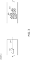
FIG. 3 illustrates a first step (step S001) of an installation method for the existingrefrigerant cycle apparatus 200. -
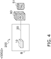
FIG. 4 illustrates a second step (step S002) of the installation method for the existingrefrigerant cycle apparatus 200. -
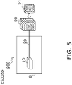
FIG. 5 illustrates a third step (step S003) of the installation method for the existingrefrigerant cycle apparatus 200. -
FIG. 6 illustrates a fourth step (step S004) of the installation method for the existingrefrigerant cycle apparatus 200. -
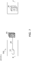
FIG. 7 illustrates a first step (step S101) of an installation method according to a first embodiment. -
FIG. 8 illustrates a second step (step S102) of the installation method according to the first embodiment. -
FIG. 9 illustrates a third step (step S103) of the installation method according to the first embodiment. -
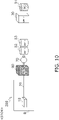
FIG. 10 illustrates a fourth step (step S104) of the installation method according to the first embodiment. -
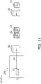
FIG. 11 illustrates a fifth step (step S105) of the installation method according to the first embodiment. -
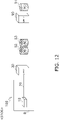
FIG. 12 illustrates a sixth step (step S106) of the installation method according to the first embodiment. -
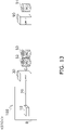
FIG. 13 illustrates a seventh step (step S107) of the installation method according to the first embodiment. -
FIG. 14 illustrates an eighth step (step S108) of the installation method according to the first embodiment. -
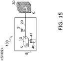
FIG. 15 illustrates a ninth step (step S109) of the installation method according to the first embodiment. -
FIG. 16 illustrates a first step (step S201) of an installation method according to a second embodiment. -
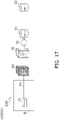
FIG. 17 illustrates a second step (step S202) of the installation method according to the second embodiment. -
FIG. 18 illustrates a third step (step S203) of the installation method according to the second embodiment. -
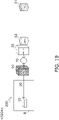
FIG. 19 illustrates a fourth step (step S204) of the installation method according to the second embodiment. -
FIG. 20 illustrates a fifth step (step S205) of the installation method according to the second embodiment. -
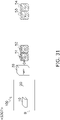
FIG. 21 illustrates a sixth step (step S206) of the installation method according to the second embodiment. -
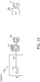
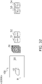
FIG. 22 illustrates a seventh step (step S207) of the installation method according to the second embodiment. -
FIG. 23 illustrates an eighth step (step S208) of the installation method according to the second embodiment. -
FIG. 24 illustrates a ninth step (step S209) of the installation method according to the second embodiment. -
FIG. 25 illustrates a first step (step S301) of an installation method according to a third embodiment. -
FIG. 26 illustrates a second step (step S302) of the installation method according to the third embodiment. -
FIG. 27 illustrates a third step (step S303) of the installation method according to the third embodiment. -
FIG. 28 illustrates a fourth step (step S304) of the installation method according to the third embodiment. -
FIG. 29 illustrates a fifth step (step S305) of the installation method according to the third embodiment. -
FIG. 30 illustrates a sixth step (step S306) of the installation method according to the third embodiment. -
FIG. 31 illustrates a seventh step (step S307) of the installation method according to the third embodiment. -
FIG. 32 illustrates an eighth step (step S308) of the installation method according to the third embodiment. -
FIG. 33 illustrates a ninth step (step S309) of the installation method according to the third embodiment. - In the present disclosure, two types of refrigerants, a first refrigerant R1 and a second refrigerant R2, are used.
- The first refrigerant R1 has a first GWP and at least one of flammability or toxicity. As used herein, the term "flammability" includes Class A2L ("low flammability"), Class A2 ("flammability"), and Class A3 ("high flammability") in the safety classification designated in ISO 817. Furthermore, as used herein, "toxicity" includes Class B2L, Class B2, and Class B3 in the safety classification designated in ISO 817.
- The second refrigerant R2 has a second GWP and at least one of non-flammability or non-toxicity. The second GWP is larger than the first GWP. The second refrigerant R2 may be, for example, a mixed refrigerant including a component identical to a component of the first refrigerant R1.
- The first refrigerant R1 is, for example, R32. The second refrigerant R2 is, for example, R410A.
-
FIG. 1 illustrates a configuration of arefrigerant cycle apparatus 100 installed by an installation method of the present disclosure. Therefrigerant cycle apparatus 100 provides cold or heat to a user by circulating the second refrigerant R2. Therefrigerant cycle apparatus 100 may be configured as any product including, for example, an air conditioner, a refrigerator, a freezer, a water heater, or a floor heater. In the present disclosure, therefrigerant cycle apparatus 100 will be described as an air conditioner. - The
refrigerant cycle apparatus 100 includes autilization unit 10, a connection piping 20, a firstheat source unit 30, and aremote controller 40. - The
refrigerant cycle apparatus 100 includes one or a plurality ofutilization units 10. Theutilization unit 10 is installed in a room used by the user. Oneutilization unit 10 includes a utilization expansion valve 11, autilization heat exchanger 12, and autilization fan 13. - The utilization expansion valve 11 controls a flow rate of the second refrigerant R2. The utilization expansion valve 11 functions as a decompressor for the second refrigerant R2, and thus, for example, can change the second refrigerant R2 in a liquid state into the second refrigerant R2 in a gas-liquid two-phase state.
- The
utilization heat exchanger 12 exchanges heat between the second refrigerant R2 and air. When therefrigerant cycle apparatus 100 performs a cooling operation, theutilization heat exchanger 12 functions as an evaporator or a heat absorber for the second refrigerant R2. When therefrigerant cycle apparatus 100 performs a heating operation, theutilization heat exchanger 12 functions as a condenser or a heat radiator for the second refrigerant R2. - The
utilization fan 13 generates an air flow passing through theutilization heat exchanger 12 to promote heat exchange at theutilization heat exchanger 12. - The
connection piping 20 connects theutilization unit 10 and the firstheat source unit 30. Theconnection piping 20 includes a liquidrefrigerant pipe 21 and agas refrigerant pipe 22. The liquidrefrigerant pipe 21 principally guides, for example, the second refrigerant R2 in a liquid state or in a gas-liquid two-phase state. Thegas refrigerant pipe 22 principally guides, for example, the second refrigerant R2 in a gas state. - The first
heat source unit 30 is installed outside the room used by the user, typically outdoors. The firstheat source unit 30 includes acompressor 31, a four-way switching valve 32, a heatsource heat exchanger 33, aheat source fan 34, a heatsource expansion valve 35, a liquidrefrigerant port 36, agas refrigerant port 37, and first lubricating oil L1. - The
compressor 31 sucks the second refrigerant R2 in a low-pressure gas state and discharges the second refrigerant R2 in a high-pressure gas state. - The four-
way switching valve 32 changes connection of pipes. During cooling operation, the four-way switching valve 32 achieves connection depicted by solid lines inFIG. 1 . During heating operation, the four-way switching valve 32 achieves connection depicted by broken lines inFIG. 1 . - The heat
source heat exchanger 33 exchanges heat between the second refrigerant R2 and air. When therefrigerant cycle apparatus 100 performs a cooling operation, the heatsource heat exchanger 33 functions as a condenser or a heat radiator for the second refrigerant R2. When therefrigerant cycle apparatus 100 performs the heating operation, the heatsource heat exchanger 33 functions as an evaporator or a heat absorber for the second refrigerant R2. - The
heat source fan 34 generates an air flow passing through the heatsource heat exchanger 33 to promote heat exchange at the heatsource heat exchanger 33. - The heat
source expansion valve 35 controls a flow rate of the second refrigerant R2. The heatsource expansion valve 35 functions as a decompressor for the second refrigerant R2, and thus, for example, can change the second refrigerant R2 in a liquid state into the second refrigerant R2 in a gas-liquid two-phase state. - The
refrigerant cycle apparatus 100 may include only one of the utilization expansion valve 11 or the heatsource expansion valve 35. - The liquid
refrigerant port 36 is an openable and closable valve. The liquidrefrigerant port 36 is connected to the liquidrefrigerant pipe 21. The liquidrefrigerant port 36 is opened when therefrigerant cycle apparatus 100 is used. The liquidrefrigerant port 36 is closed when the firstheat source unit 30 is installed, for example. - The
gas refrigerant port 37 is an openable and closable valve. Thegas refrigerant port 37 is connected to thegas refrigerant pipe 22. Thegas refrigerant port 37 is opened when therefrigerant cycle apparatus 100 is used. Thegas refrigerant port 37 is closed when the firstheat source unit 30 is installed, for example. - The first
heat source unit 30 accommodates the first lubricating oil L1 for lubricating a sliding portion of thecompressor 31. - The
remote controller 40 is provided so as to correspond to eachutilization unit 10. Theremote controller 40 enables the user to provide an instruction to therefrigerant cycle apparatus 100. Theremote controller 40 can communicate with theutilization unit 10. -
FIG. 2 illustrates an example of an existingrefrigerant cycle apparatus 200 that has been operated before therefrigerant cycle apparatus 100 is installed. The existingrefrigerant cycle apparatus 200 is an existing facility. - The existing
refrigerant cycle apparatus 200 includes theutilization unit 10, the connection piping 20, and a secondheat source unit 90. The existingrefrigerant cycle apparatus 200 uses the second refrigerant R2. - The
utilization unit 10 of the existingrefrigerant cycle apparatus 200 is the same as theutilization unit 10 included in therefrigerant cycle apparatus 100. - The connection piping 20 of the existing
refrigerant cycle apparatus 200 is the same as the connection piping 20 included in therefrigerant cycle apparatus 100. - The second
heat source unit 90 of the existingrefrigerant cycle apparatus 200 is different from the firstheat source unit 30 included in therefrigerant cycle apparatus 100. The secondheat source unit 90 includes acompressor 91, the four-way switching valve 32, a heatsource heat exchanger 93, aheat source fan 94, a heatsource expansion valve 95, a liquidrefrigerant port 96, and agas refrigerant port 97. These constituent parts have functions similar to functions of constituent parts of the firstheat source unit 30. The secondheat source unit 90 is assumed to be a product of an older model than the firstheat source unit 30. - The second
heat source unit 90 accommodates second lubricating oil L2 for lubricating a sliding portion of thecompressor 91. - The existing
refrigerant cycle apparatus 200 is installed by the following method. - As illustrated in
FIG. 3 , the secondheat source unit 90 waiting for shipment in a factory F already accommodates a predetermined amount of the second refrigerant R2. This is because, if a refrigerant circuit of the secondheat source unit 90 is evacuated or filled with air, the secondheat source unit 90 could be damaged by transportation. - In the factory F, a
refrigerant storage container 51 that accommodates the second refrigerant R2 for additional filling is prepared. In the present description, it is assumed that the number ofrefrigerant storage containers 51 is one. Alternatively, the number ofrefrigerant storage containers 51 may be two or more. - One or a plurality of
utilization units 10 and the connection piping 20 are installed in a building B. - As illustrated in
FIG. 4 , the secondheat source unit 90 and therefrigerant storage container 51 are transported to the building B. Theconnection piping 20 is connected to the liquidrefrigerant port 96 and thegas refrigerant port 97 of the secondheat source unit 90. Accordingly, the existingrefrigerant cycle apparatus 200 is configured. - As illustrated in
FIG. 5 , the secondheat source unit 90 is additionally filled with the second refrigerant R2 accommodated in therefrigerant storage container 51. - As illustrated in
FIG. 6 , the existingrefrigerant cycle apparatus 200 receives the second refrigerant R2 in an amount required by the existingrefrigerant cycle apparatus 200 as a whole. Accordingly, the existingrefrigerant cycle apparatus 200 can be used. - An installation method according to a first embodiment will be described. In this installation method, the second
heat source unit 90 included in the existingrefrigerant cycle apparatus 200 is replaced with the firstheat source unit 30 to be newly shipped. Specifically, therefrigerant cycle apparatus 100 is installed by the following method. - As illustrated in
FIG. 7 , the existingrefrigerant cycle apparatus 200 using the second refrigerant R2 is installed in the building B. The firstheat source unit 30 accommodates a predetermined amount of the first refrigerant R1 waiting for shipment in the factory F. - As illustrated in
FIG. 8 , the firstheat source unit 30 is transported to the building B. A firstrefrigerant storage container 51, a secondrefrigerant storage container 52, and a thirdrefrigerant storage container 53 that are empty are prepared near the building B. In the present description, it is assumed that the number of the firstrefrigerant storage containers 51, the number of the secondrefrigerant storage containers 52, and the number of the thirdrefrigerant storage containers 53 are all one. Alternatively, the numbers may be two or more. - Next, the first refrigerant R1 is recovered from the first
heat source unit 30. At this time, the first refrigerant R1 in a gas state may be recovered from the firstheat source unit 30 through thegas refrigerant port 37. During the recovery of the first refrigerant R1, the first lubricating oil L1 accommodated in the firstheat source unit 30 may be left in the firstheat source unit 30. By recovering the first refrigerant R1 in a gas state, the first lubricating oil L1 in a liquid state can remain in the firstheat source unit 30. - The recovered first refrigerant R1 is regenerated by a
refrigerant regenerator 70. In this regeneration processing, therefrigerant regenerator 70 may remove water included in the first refrigerant R1 from the first refrigerant R1. - The regenerated first refrigerant R1 is transferred from the
refrigerant regenerator 70 to the firstrefrigerant storage container 51. - As illustrated in
FIG. 9 , the firstrefrigerant storage container 51 finishes accommodating the first refrigerant R1. In the firstheat source unit 30, almost no first refrigerant R1 is present. - As illustrated in
FIG. 10 , the second refrigerant R2 is recovered from the secondheat source unit 90 of the existingrefrigerant cycle apparatus 200. At this time, the second refrigerant R2 is regenerated by therefrigerant regenerator 70. In this regeneration processing, therefrigerant regenerator 70 removes at least one of the second lubricating oil L2 or water included in the second refrigerant R2 from the second refrigerant R2. Preferably, therefrigerant regenerator 70 removes the second lubricating oil L2 from the second refrigerant R2. Therefrigerant regenerator 70 may remove both the second lubricating oil L2 and water from the second refrigerant R2. - The regenerated second refrigerant R2 is transferred from the
refrigerant regenerator 70 to the secondrefrigerant storage container 52 and the thirdrefrigerant storage container 53. - As illustrated in
FIG. 11 , the secondrefrigerant storage container 52 and the thirdrefrigerant storage container 53 finish accommodating the second refrigerant R2. In the secondheat source unit 90, almost no second refrigerant R2 is present. - As illustrated in
FIG. 12 , the secondheat source unit 90 is disconnected from the connection piping 20 of the existingrefrigerant cycle apparatus 200. This disconnection may be performed by closing the liquidrefrigerant port 96 and thegas refrigerant port 97 configured by openable and closable valves, which does not necessarily involve removal of the secondheat source unit 90. - Next, the first
heat source unit 30 is connected to theconnection piping 20. Accordingly, therefrigerant cycle apparatus 100 is configured. - As illustrated in
FIG. 13 , the regenerated second refrigerant R2 accommodated in the secondrefrigerant storage container 52 and the thirdrefrigerant storage container 53 is accommodated in the firstheat source unit 30. - As illustrated in
FIG. 14 , therefrigerant cycle apparatus 100 receives the second refrigerant R2 in an amount required by therefrigerant cycle apparatus 100 as a whole. Accordingly, therefrigerant cycle apparatus 100 can be used. - As illustrated in
FIG. 15 , a display S indicating that the second refrigerant R2 is used is attached to at least a part of theutilization unit 10, the connection piping 20, and the firstheat source unit 30. Theremote controller 40 may include adisplay unit 41 that electrically displays that the second refrigerant R2 is used. - The
display unit 41 may display not only the name of the second refrigerant R2 but also at least part of the properties (for example, flammability or non-flammability, toxicity or non-toxicity, specific gravity, or the like) of the second refrigerant R2, the fact that the second refrigerant R2 accommodated in therefrigerant cycle unit 100 has been once recovered from any refrigerant circuit, and the fact that the second refrigerant R2 accommodated in therefrigerant cycle unit 100 has been regenerated. Thedisplay unit 41 may display the above information not only as characters but also in a form such as a bar code or a QR code (registered trademark). - An optimum operation of the refrigerant cycle apparatus 100 (for example, an opening degree of the expansion valve and a number of rotations of the compressor) varies depending on a type of refrigerant used. Thus, a control unit of the
refrigerant cycle apparatus 100 needs to know the type of refrigerant to be used. - The
refrigerant cycle apparatus 100 may include a refrigerant setting switch for the purpose of notifying the control unit of the type of refrigerant. In this case, an installation operator can manually switch the refrigerant setting switch to notify the control unit of the type of refrigerant. The control unit can change the operation of therefrigeration cycle apparatus 100 in accordance with the type of refrigerant designated by the refrigerant setting switch. - Alternatively, the control unit of the
refrigerant cycle apparatus 100 may automatically recognize the type of refrigerant. For example, the control unit can recognize the type of refrigerant used by knowing a balance point of a refrigerant cycle. - (3-1)
In the installation method according to the present embodiment, the second refrigerant R2 can be used in therefrigerant cycle apparatus 100 configured using a new firstheat source unit 30. Therefore, therefrigerant cycle apparatus 100 of a new model can be installed in an environment that does not permit use of the first refrigerant R1 having flammability or toxicity. - (3-2)
In the installation method according to the present embodiment, therefrigerant cycle apparatus 100 of a new model can be configured using a part of the existingrefrigerant cycle apparatus 200. Therefore, costs of therefrigerant cycle apparatus 100 can be reduced. - (3-3)
In the installation method according to the present embodiment, the second refrigerant R2 is accommodated in the secondrefrigerant storage container 52 and the thirdrefrigerant storage container 53. It is therefore easy to know the amount of the recovered second refrigerant R2 by the number of refrigerant storage containers used. - (3-4)
In the installation method according to the present embodiment, at least one of the second lubricating oil L2 or water is removed from the second refrigerant R2. Therefore, the recovered second refrigerant R2 can be reused in an apparatus that does not permit mixing of the second lubricating oil L2 or water. - (3-5)
In the installation method according to the present embodiment, the first lubricating oil L1 may be left in the firstheat source unit 30. Therefore, when the second refrigerant R2 permits the use of the first lubricating oil L1, an installation cost can be reduced. - (3-6)
In the installation method according to the present embodiment, the first refrigerant R1 may be recovered in a gas state from the firstheat source unit 30. It is therefore possible to suppress a situation in which the first lubricating oil L1 accommodated in the firstheat source unit 30 is taken out from the firstheat source unit 30 together with the first refrigerant R1. - (3-7)
In the installation method according to the present embodiment, the first refrigerant R1 recovered from the firstheat source unit 30 is regenerated. Therefore, the first refrigerant R1 can be reused. - (3-8)
The installation method according to the present embodiment enables a maintenance worker of therefrigerant cycle apparatus 100 to easily understand that the second refrigerant R2 is used in therefrigerant cycle apparatus 100 by viewing the display S or thedisplay unit 41. It is therefore possible to suppress a situation in which therefrigerant cycle apparatus 100 is used in an incorrect manner. - (3-9)
In the installation method according to the present embodiment, the second refrigerant R2 may include a component identical to the component of the first refrigerant R1. Thus, the first refrigerant R1 recovered in the step of recovering the first refrigerant R1 can be reused in therefrigerant cycle apparatus 100. - For example, a case where the first refrigerant R1 is R32 and the second refrigerant R2 is R410A is considered. R410 is a mixture of R32 and R125. Thus, the first refrigerant R1 (or R32) recovered and regenerated from the existing
refrigerant cycle apparatus 200 can be used as a raw material of the regenerated second refrigerant R2 (or R410A) used in therefrigerant cycle apparatus 100. - By regenerating the recovered first refrigerant R1 in this manner, the regenerated first refrigerant R1 can be used in a different apparatus.
- (3-10)
In the installation method according to the present embodiment, by regenerating the second refrigerant R2 recovered from the existingrefrigerant cycle apparatus 200, a production amount of the second refrigerant R2 having a large second GWP can be reduced as compared with a case where the installation method according to the present embodiment is not used. Therefore, global warming can be suppressed. - (3-11)
Therefrigerant cycle apparatus 100 according to the present embodiment uses the second refrigerant R2. Therefore, therefrigerant cycle apparatus 100 using the firstheat source unit 30 of a new model can be used in an environment that does not permit use of the first refrigerant R1. - (3-12)
The maintenance worker of therefrigerant cycle apparatus 100 can easily obtain information on the refrigerant used in therefrigerant cycle apparatus 100 according to the present embodiment by viewing the display S or thedisplay unit 41. It is therefore possible to suppress a situation in which therefrigerant cycle apparatus 100 is used in an incorrect manner. - An installation method according to a second embodiment will be described. This installation method is different from the installation method according to the first embodiment in that the first
heat source unit 30 is used as a refrigerant storage container for accommodating the second refrigerant R2. - In the installation method according to the second embodiment, the second
heat source unit 90 included in the existingrefrigerant cycle apparatus 200 is replaced with the firstheat source unit 30 to be newly shipped, as in the first embodiment. - As illustrated in
FIG. 16 , the existingrefrigerant cycle apparatus 200 using the second refrigerant R2 is installed in the building B. The firstheat source unit 30 accommodates a predetermined amount of the first refrigerant R1 waiting for shipment in the factory F. - As illustrated in
FIG. 17 , the firstheat source unit 30 is transported to the building B. The firstrefrigerant storage container 51 and the secondrefrigerant storage container 52 that are empty are prepared near the building B. In the present description, it is assumed that the number of the firstrefrigerant storage containers 51 and the number of the secondrefrigerant storage containers 52 are both one. Alternatively, the numbers may be two or more. - Next, the first refrigerant R1 is recovered from the first
heat source unit 30. At this time, the first refrigerant R1 in a gas state may be recovered from the firstheat source unit 30 through thegas refrigerant port 37. During the recovery of the first refrigerant R1, the first lubricating oil L1 accommodated in the firstheat source unit 30 may be left in the firstheat source unit 30. By recovering the first refrigerant R1 in a gas state, the first lubricating oil L1 in a liquid state can remain in the firstheat source unit 30. - The recovered first refrigerant R1 is regenerated by a
refrigerant regenerator 70. In this regeneration processing, therefrigerant regenerator 70 may remove water included in the first refrigerant R1 from the first refrigerant R1. - The regenerated first refrigerant R1 is transferred from the
refrigerant regenerator 70 to the firstrefrigerant storage container 51. - As illustrated in
FIG. 18 , the firstrefrigerant storage container 51 finishes accommodating the first refrigerant R1. In the firstheat source unit 30, almost no first refrigerant R1 is present. - As illustrated in
FIG. 19 , the second refrigerant R2 is recovered from the secondheat source unit 90 of the existingrefrigerant cycle apparatus 200. At this time, the second refrigerant R2 is regenerated by therefrigerant regenerator 70. In this regeneration processing, therefrigerant regenerator 70 removes at least one of the second lubricating oil L2 or water included in the second refrigerant R2 from the second refrigerant R2. Preferably, therefrigerant regenerator 70 removes the second lubricating oil L2 from the second refrigerant R2. Therefrigerant regenerator 70 may remove both the second lubricating oil L2 and water from the second refrigerant R2. - The regenerated second refrigerant R2 is transferred from the
refrigerant regenerator 70 to the firstheat source unit 30 and the secondrefrigerant storage container 52. - As illustrated in
FIG. 20 , the firstheat source unit 30 and the secondrefrigerant storage container 52 finish accommodating the second refrigerant R2. In the secondheat source unit 90, almost no second refrigerant R2 is present. - As illustrated in
FIG. 21 , the secondheat source unit 90 is disconnected from the connection piping 20 of the existingrefrigerant cycle apparatus 200. Next, the firstheat source unit 30 is connected to theconnection piping 20. Accordingly, therefrigerant cycle apparatus 100 is configured. - As illustrated in
FIG. 22 , the regenerated second refrigerant R2 included in the secondrefrigerant storage container 52 is additionally accommodated in the firstheat source unit 30. - As illustrated in
FIG. 23 , therefrigerant cycle apparatus 100 receives the second refrigerant R2 in an amount required by therefrigerant cycle apparatus 100 as a whole. Accordingly, therefrigerant cycle apparatus 100 can be used. - As illustrated in
FIG. 24 , the display S indicating that the second refrigerant R2 is used is attached to at least a part of theutilization unit 10, the connection piping 20, or the firstheat source unit 30. Theremote controller 40 may include adisplay unit 41 that electrically displays that the second refrigerant R2 is used. The content and form of the information displayed on thedisplay unit 41 are similar to those in the first embodiment. - The setting of the type of refrigerant in the second embodiment is similar to that in the first embodiment.
- In the installation method according to the present embodiment, the first
heat source unit 30 is used as a storage container for the second refrigerant R2. Therefore, since the number of refrigerant storage containers required for installing therefrigerant cycle apparatus 100 can be reduced, the installation cost can be reduced. - An installation method according to a third embodiment will be described. In this installation method, unlike the first embodiment and the second embodiment, the second refrigerant R2 recovered from a separate-system
refrigerant cycle apparatus 300 that does not share constituent parts with therefrigerant cycle apparatus 100 is used in therefrigerant cycle apparatus 100. The separate-systemrefrigerant cycle apparatus 300 of a different system is an existing facility. Therefrigerant cycle apparatus 100 is installed by the following method. - As illustrated in
FIG. 25 , the separate-systemrefrigerant cycle apparatus 300 using the second refrigerant R2 is installed in a building C. The separate-systemrefrigerant cycle apparatus 300 includes autilization unit 310, aconnection pipe 320, and a thirdheat source unit 390. - As illustrated in
FIG. 26 , the firstrefrigerant storage container 51 and the secondrefrigerant storage container 52 that are empty are prepared near the building C. In the present description, it is assumed that the number of the firstrefrigerant storage containers 51 and the number of the secondrefrigerant storage containers 52 are both one. Alternatively, the numbers may be two or more. - Next, the second refrigerant R2 is recovered from the third
heat source unit 390. The recovered second refrigerant R2 is regenerated by therefrigerant regenerator 70. The regenerated second refrigerant R2 is transferred from therefrigerant regenerator 70 to the firstrefrigerant storage container 51 and the secondrefrigerant storage container 52. - As illustrated in
FIG. 27 , the firstrefrigerant storage container 51 and the secondrefrigerant storage container 52 finish accommodating the second refrigerant R2. - As illustrated in
FIG. 28 , the firstrefrigerant storage container 51 and the secondrefrigerant storage container 52 are transported to near the building B. The thirdrefrigerant storage container 53 and the fourthrefrigerant storage container 54 that are empty are prepared near the building B. In the present description, it is assumed that the number of the thirdrefrigerant storage containers 53 and the number of the fourthrefrigerant storage containers 54 are both one. Alternatively, the numbers may be two or more. - In the building B, the
refrigerant cycle apparatus 100 is installed using a new firstheat source unit 30. Therefrigerant cycle apparatus 100 is filled with the first refrigerant R1. - As illustrated in
FIG. 29 , the first refrigerant R1 is recovered from the firstheat source unit 30 of therefrigerant cycle apparatus 100. During the recovery of the first refrigerant R1, the first lubricating oil L1 accommodated in the firstheat source unit 30 may be left in the firstheat source unit 30. - The recovered first refrigerant R1 is regenerated by a
refrigerant regenerator 70. In this regeneration processing, therefrigerant regenerator 70 may remove water included in the first refrigerant R1 from the first refrigerant R1. - As illustrated in
FIG. 30 , the regenerated first refrigerant R1 is transferred from therefrigerant regenerator 70 to the thirdrefrigerant storage container 53 and the fourthrefrigerant storage container 54. In the firstheat source unit 30, almost no first refrigerant R1 is present. - As illustrated in
FIG. 31 , the regenerated second refrigerant R2 accommodated in the firstrefrigerant storage container 51 and the secondrefrigerant storage container 52 is accommodated in the firstheat source unit 30. - As illustrated in
FIG. 32 , therefrigerant cycle apparatus 100 receives the second refrigerant R2 in an amount required by therefrigerant cycle apparatus 100 as a whole. Accordingly, therefrigerant cycle apparatus 100 can be used. - As illustrated in
FIG. 33 , the display S indicating that the second refrigerant R2 is used is attached to at least a part of theutilization unit 10, the connection piping 20, or the firstheat source unit 30. Theremote controller 40 may include adisplay unit 41 that electrically displays that the second refrigerant R2 is used. The content and form of the information displayed on thedisplay unit 41 are similar to those in the first embodiment. - The setting of the type of refrigerant in the third embodiment is similar to that in the first embodiment.
- In the installation method according to the present embodiment, the
refrigerant cycle apparatus 100 that is new as a whole can be installed using the firstheat source unit 30 of a new mode. - Although the embodiments of the present disclosure have been described above, it will be understood that various changes in form and details can be made without departing from the spirit and scope of the present disclosure described in claims.
-
- 10: utilization unit
- 20: connection pipe
- 30: first heat source unit
- 36: liquid refrigerant port
- 37: gas refrigerant port
- 40: remote controller
- 41: display unit
- 51: first refrigerant storage container (refrigerant storage container)
- 52: second refrigerant storage container (refrigerant storage container)
- 53: third refrigerant storage container (refrigerant storage container)
- 54: fourth refrigerant storage container (refrigerant storage container)
- 70: refrigerant regenerator
- 90: second heat source unit
- 100: refrigerant cycle apparatus
- 200: existing refrigerant cycle apparatus (existing facility)
- 300: separate-system refrigerant cycle apparatus (existing facility)
- 310: utilization unit (constituent part)
- 320: connection pipe (constituent part)
- 390: third heat source unit (constituent part)
- L1: first lubricating oil
- L2: second lubricating oil
- R1: first refrigerant
- R2: second refrigerant
- S: display
- S001: step
- S002: step
- S003: step
- S004: step
- S101: step
- S102: step (first refrigerant recovery step) (first refrigerant regeneration step)
- S103: step
- S104: step (second refrigerant recovery and regeneration step)
- S105: step
- S106: step (disconnection step) (connection step)
- S107: step (second refrigerant accommodation step)
- S108: step
- S109: step (second refrigerant display step)
- S201: step
- S202: step (first refrigerant recovery step) (first refrigerant regeneration step)
- S203: step
- S204: step (second refrigerant accommodation step) (second refrigerant recovery and regeneration step)
- S205: step
- S206: step (disconnection step) (connection step)
- S207: step (second refrigerant accommodation step)
- S208: step
- S209: step (second refrigerant display step)
- S301: step
- S302: step (second refrigerant recovery and regeneration step)
- S303: step
- S304: step
- S305: step (first refrigerant recovery step) (first refrigerant regeneration step)
- S306: step
- S307: step (second refrigerant accommodation step)
- S308: step
- S309: step (second refrigerant display step)
- Patent Literature 1:
EP 3505842 A1
Claims (14)
- An installation method for a refrigerant cycle apparatus (100) including a first heat source unit (30), a utilization unit (10), and a connection pipe (20), the installation method comprising:a first refrigerant recovery step (S102, S202, S305) of recovering a first refrigerant (R1) having a first GWP and at least one of flammability or toxicity from the first heat source unit; anda second refrigerant accommodation step (S107, S204, S207, S307) of accommodating, in the first heat source unit, a second refrigerant (R2) recovered and regenerated from an existing facility (200, 300) and having a second GWP and at least one of non-flammability or non-toxicity.
- The installation method according to claim 1, whereinthe existing facility is an existing refrigerant cycle apparatus (200) including a second heat source unit (90), the utilization unit, and the connection pipe, andthe installation method further includesa second refrigerant recovery and regeneration step (S104, S204) of recovering the second refrigerant from the existing facility and regenerating the second refrigerant,a disconnection step (S106, S206) of disconnecting the second heat source unit from the existing refrigerant cycle apparatus, anda connection step (S106, S206) of connecting the first heat source unit to the connection pipe to configure the refrigerant cycle apparatus.
- The installation method according to claim 1, whereinthe existing facility is a separate-system refrigerant cycle apparatus (300) including a constituent part (310, 320, 390) different from the utilization unit and the connection pipe, andthe installation method further includes a second refrigerant recovery and regeneration step (S302) of recovering the second refrigerant from the existing facility and regenerating the second refrigerant.
- The installation method according to claim 2 or 3, wherein
in the second refrigerant recovery and regeneration step, the second refrigerant is accommodated at least in a refrigerant storage container (52, 53, 54). - The installation method according to any one of claims 2 to 4, wherein
in the second refrigerant recovery and regeneration step, the second refrigerant is accommodated in at least the first heat source unit. - The installation method according to any one of claims 2 to 5, wherein
in the second refrigerant recovery and regeneration step, at least one of second lubricating oil (L2) or water included in the second refrigerant is removed from the second refrigerant. - The installation method according to any one of claims 1 to 6, wherein
in the first refrigerant recovery step, first lubricating oil (L1) accommodated in the first heat source unit is left in the first heat source unit. - The installation method according to any one of claims 1 to 7, whereinthe first heat source unit includes a gas refrigerant port (37) and a liquid refrigerant port (36), andin the first refrigerant recovery step, the first refrigerant is recovered from the first heat source unit through the gas refrigerant port.
- The installation method according to any one of claims 1 to 8, further comprising
a first refrigerant regeneration step (S102, S202, S305) of regenerating the first refrigerant recovered in the first refrigerant recovery step. - The installation method according to any one of claims 1 to 9, further comprising
a second refrigerant display step (S109, S209, S309) of attaching, to at least the first heat source unit, a display (S) indicating that the second refrigerant is used. - The installation method according to any one of claims 1 to 10, wherein
the second refrigerant is a mixed refrigerant including a component identical to a component of the first refrigerant. - The installation method according to any one of claims 1 to 11, wherein
the second GWP is larger than the first GWP. - A refrigerant cycle apparatus (100) comprising:a first heat source unit (30), wherein the first heat source unit accommodates a second refrigerant (R2) after a first refrigerant (R1) accommodated in the first heat source unit is taken out, the first refrigerant has a first GWP and has at least one of flammability or toxicity, the second refrigerant has a second GWP and at least one of non-flammability or non-toxicity, and the second refrigerant is recovered and regenerated from an existing facility (200, 300);a utilization unit (10); anda connection pipe (20) that connects the first heat source unit and the utilization unit.
- The refrigerant cycle apparatus according to claim 13, further comprising
a remote controller (40) including a display unit (41) configured to display information on a refrigerant accommodated in the first heat source unit.
Applications Claiming Priority (1)
| Application Number | Priority Date | Filing Date | Title |
|---|---|---|---|
| PCT/JP2020/009279 WO2021176625A1 (en) | 2020-03-04 | 2020-03-04 | Refrigerant cycle apparatus and method for installing refrigerant cycle apparatus |
Publications (3)
| Publication Number | Publication Date |
|---|---|
| EP4116643A1 true EP4116643A1 (en) | 2023-01-11 |
| EP4116643A4 EP4116643A4 (en) | 2023-11-15 |
| EP4116643B1 EP4116643B1 (en) | 2024-10-16 |
Family
ID=77613206
Family Applications (1)
| Application Number | Title | Priority Date | Filing Date |
|---|---|---|---|
| EP20923458.2A Active EP4116643B1 (en) | 2020-03-04 | 2020-03-04 | Method for installing refrigerant cycle apparatus |
Country Status (5)
| Country | Link |
|---|---|
| US (1) | US12345454B2 (en) |
| EP (1) | EP4116643B1 (en) |
| JP (1) | JP7437489B2 (en) |
| CN (1) | CN115244347B (en) |
| WO (1) | WO2021176625A1 (en) |
Family Cites Families (20)
| Publication number | Priority date | Publication date | Assignee | Title |
|---|---|---|---|---|
| US4441330A (en) * | 1980-12-01 | 1984-04-10 | Robinair Manufacturing Corporation | Refrigerant recovery and recharging system |
| US5231841A (en) * | 1991-12-19 | 1993-08-03 | Mcclelland Ralph A | Refrigerant charging system and control system therefor |
| JP3239494B2 (en) | 1992-12-22 | 2001-12-17 | 株式会社日立製作所 | Refrigeration equipment |
| JPH06273007A (en) * | 1993-03-25 | 1994-09-30 | Hitachi Ltd | Retrofit working method of air conditioning apparatus |
| JPH07190535A (en) | 1993-12-27 | 1995-07-28 | Toshiba Corp | Refrigeration cycle control device |
| JPH07253250A (en) | 1994-03-15 | 1995-10-03 | Toshiba Corp | Refrigeration cycle controller |
| JPH1038354A (en) | 1996-07-24 | 1998-02-13 | Toshiba Corp | Air conditioner |
| JP3998346B2 (en) | 1998-10-16 | 2007-10-24 | 三洋電機株式会社 | Air conditioner |
| JP2003194437A (en) * | 2001-12-25 | 2003-07-09 | Daikin Ind Ltd | Residual oil recovery method |
| JP3855901B2 (en) * | 2002-09-26 | 2006-12-13 | 三菱電機株式会社 | Refrigeration and air-conditioning cycle device handling method, refrigeration and air-conditioning cycle device refrigerant recovery mechanism |
| JP2004263948A (en) | 2003-03-03 | 2004-09-24 | Mitsubishi Electric Corp | Air conditioner |
| US7524805B2 (en) * | 2004-04-29 | 2009-04-28 | Honeywell International Inc. | Azeotrope-like compositions of tetrafluoropropene and hydrofluorocarbons |
| US7597818B2 (en) * | 2007-02-27 | 2009-10-06 | Honeywell International Inc. | Azeotrope-like compositions of tetrafluoropropenes and bromofluoropropenes |
| WO2010119705A1 (en) * | 2009-04-17 | 2010-10-21 | ダイキン工業株式会社 | Heat source unit |
| JP2011094871A (en) | 2009-10-29 | 2011-05-12 | Mitsubishi Electric Corp | Refrigerating air conditioning device and installation method of the refrigerating air conditioning device |
| US20120291457A1 (en) * | 2011-05-17 | 2012-11-22 | Service Solutions U.S. Llc | Pressure Decay Leak Check Method and Apparatus |
| JP2015064182A (en) * | 2013-09-26 | 2015-04-09 | ダイキン工業株式会社 | Air conditioner |
| EP3334989B1 (en) | 2015-08-11 | 2023-09-27 | Trane International Inc. | Refrigerant recovery and repurposing |
| JP2017067383A (en) * | 2015-09-30 | 2017-04-06 | ダイキン工業株式会社 | Freezer and operation method of freezer |
| EP4187167A1 (en) | 2017-12-26 | 2023-05-31 | Trane International Inc. | Hvac product for flammable refrigerant |
-
2020
- 2020-03-04 EP EP20923458.2A patent/EP4116643B1/en active Active
- 2020-03-04 WO PCT/JP2020/009279 patent/WO2021176625A1/en not_active Ceased
- 2020-03-04 CN CN202080097904.4A patent/CN115244347B/en active Active
- 2020-03-04 JP JP2022504863A patent/JP7437489B2/en active Active
-
2022
- 2022-08-29 US US17/898,040 patent/US12345454B2/en active Active
Also Published As
| Publication number | Publication date |
|---|---|
| WO2021176625A1 (en) | 2021-09-10 |
| US20220404080A1 (en) | 2022-12-22 |
| JP7437489B2 (en) | 2024-02-22 |
| CN115244347A (en) | 2022-10-25 |
| CN115244347B (en) | 2025-06-10 |
| JPWO2021176625A1 (en) | 2021-09-10 |
| EP4116643A4 (en) | 2023-11-15 |
| US12345454B2 (en) | 2025-07-01 |
| EP4116643B1 (en) | 2024-10-16 |
Similar Documents
| Publication | Publication Date | Title |
|---|---|---|
| EP3859223A1 (en) | Heat load processing system | |
| KR101678324B1 (en) | Refrigeration system | |
| EP3859253A1 (en) | Heat load processing system | |
| EP3040642B1 (en) | Air conditioner | |
| EP2960602B1 (en) | Air conditioner | |
| CN102052810B (en) | Refrigeration/ air-conditioning apparatus and method for setting the refrigeration/ air-conditioning apparatus | |
| EP3435006B1 (en) | Refrigeration cycle apparatus | |
| EP2623887B1 (en) | Air conditioning device | |
| EP2787297B1 (en) | Method for selecting heat medium of use-side heat exchanger during construction of air conditioning system | |
| EP2615391B1 (en) | Air-conditioning device | |
| JP6079061B2 (en) | Refrigeration equipment | |
| EP3859242B1 (en) | Refrigerant filling method | |
| EP2933582A1 (en) | Air conditioner device | |
| KR102504975B1 (en) | Refrigeration system and method | |
| WO2020014220A9 (en) | Refrigeration systems and methods | |
| EP3401609B1 (en) | Air-conditioning device | |
| US11512877B2 (en) | Air conditioning process | |
| EP4116643B1 (en) | Method for installing refrigerant cycle apparatus | |
| EP3642541B1 (en) | Cascaded refrigeration system | |
| EP3067643B1 (en) | Refrigeration cycle apparatus, and production method and installation method therefor | |
| AU2020220103A1 (en) | An Arrangement and Method for Retrofitting an Air Conditioning System | |
| KR102636893B1 (en) | Refrigeration systems and methods |
Legal Events
| Date | Code | Title | Description |
|---|---|---|---|
| STAA | Information on the status of an ep patent application or granted ep patent |
Free format text: STATUS: THE INTERNATIONAL PUBLICATION HAS BEEN MADE |
|
| PUAI | Public reference made under article 153(3) epc to a published international application that has entered the european phase |
Free format text: ORIGINAL CODE: 0009012 |
|
| STAA | Information on the status of an ep patent application or granted ep patent |
Free format text: STATUS: REQUEST FOR EXAMINATION WAS MADE |
|
| 17P | Request for examination filed |
Effective date: 20220823 |
|
| AK | Designated contracting states |
Kind code of ref document: A1 Designated state(s): AL AT BE BG CH CY CZ DE DK EE ES FI FR GB GR HR HU IE IS IT LI LT LU LV MC MK MT NL NO PL PT RO RS SE SI SK SM TR |
|
| RAP3 | Party data changed (applicant data changed or rights of an application transferred) |
Owner name: DAIKIN EUROPE N.V. Owner name: DAIKIN INDUSTRIES, LTD. |
|
| DAV | Request for validation of the european patent (deleted) | ||
| DAX | Request for extension of the european patent (deleted) | ||
| P01 | Opt-out of the competence of the unified patent court (upc) registered |
Effective date: 20230530 |
|
| A4 | Supplementary search report drawn up and despatched |
Effective date: 20231016 |
|
| RIC1 | Information provided on ipc code assigned before grant |
Ipc: F25B 49/02 20060101ALI20231010BHEP Ipc: F25B 13/00 20060101ALI20231010BHEP Ipc: F25B 45/00 20060101AFI20231010BHEP |
|
| GRAP | Despatch of communication of intention to grant a patent |
Free format text: ORIGINAL CODE: EPIDOSNIGR1 |
|
| STAA | Information on the status of an ep patent application or granted ep patent |
Free format text: STATUS: GRANT OF PATENT IS INTENDED |
|
| INTG | Intention to grant announced |
Effective date: 20240527 |
|
| GRAJ | Information related to disapproval of communication of intention to grant by the applicant or resumption of examination proceedings by the epo deleted |
Free format text: ORIGINAL CODE: EPIDOSDIGR1 |
|
| STAA | Information on the status of an ep patent application or granted ep patent |
Free format text: STATUS: REQUEST FOR EXAMINATION WAS MADE |
|
| GRAP | Despatch of communication of intention to grant a patent |
Free format text: ORIGINAL CODE: EPIDOSNIGR1 |
|
| STAA | Information on the status of an ep patent application or granted ep patent |
Free format text: STATUS: GRANT OF PATENT IS INTENDED |
|
| INTC | Intention to grant announced (deleted) | ||
| GRAS | Grant fee paid |
Free format text: ORIGINAL CODE: EPIDOSNIGR3 |
|
| GRAA | (expected) grant |
Free format text: ORIGINAL CODE: 0009210 |
|
| STAA | Information on the status of an ep patent application or granted ep patent |
Free format text: STATUS: THE PATENT HAS BEEN GRANTED |
|
| INTG | Intention to grant announced |
Effective date: 20240814 |
|
| AK | Designated contracting states |
Kind code of ref document: B1 Designated state(s): AL AT BE BG CH CY CZ DE DK EE ES FI FR GB GR HR HU IE IS IT LI LT LU LV MC MK MT NL NO PL PT RO RS SE SI SK SM TR |
|
| REG | Reference to a national code |
Ref country code: GB Ref legal event code: FG4D |
|
| REG | Reference to a national code |
Ref country code: CH Ref legal event code: EP |
|
| REG | Reference to a national code |
Ref country code: IE Ref legal event code: FG4D |
|
| REG | Reference to a national code |
Ref country code: DE Ref legal event code: R096 Ref document number: 602020039738 Country of ref document: DE |
|
| REG | Reference to a national code |
Ref country code: LT Ref legal event code: MG9D |
|
| REG | Reference to a national code |
Ref country code: NL Ref legal event code: MP Effective date: 20241016 |
|
| REG | Reference to a national code |
Ref country code: AT Ref legal event code: MK05 Ref document number: 1733200 Country of ref document: AT Kind code of ref document: T Effective date: 20241016 |
|
| PG25 | Lapsed in a contracting state [announced via postgrant information from national office to epo] |
Ref country code: NL Free format text: LAPSE BECAUSE OF FAILURE TO SUBMIT A TRANSLATION OF THE DESCRIPTION OR TO PAY THE FEE WITHIN THE PRESCRIBED TIME-LIMIT Effective date: 20241016 |
|
| PG25 | Lapsed in a contracting state [announced via postgrant information from national office to epo] |
Ref country code: NL Free format text: LAPSE BECAUSE OF FAILURE TO SUBMIT A TRANSLATION OF THE DESCRIPTION OR TO PAY THE FEE WITHIN THE PRESCRIBED TIME-LIMIT Effective date: 20241016 |
|
| PG25 | Lapsed in a contracting state [announced via postgrant information from national office to epo] |
Ref country code: HR Free format text: LAPSE BECAUSE OF FAILURE TO SUBMIT A TRANSLATION OF THE DESCRIPTION OR TO PAY THE FEE WITHIN THE PRESCRIBED TIME-LIMIT Effective date: 20241016 Ref country code: IS Free format text: LAPSE BECAUSE OF FAILURE TO SUBMIT A TRANSLATION OF THE DESCRIPTION OR TO PAY THE FEE WITHIN THE PRESCRIBED TIME-LIMIT Effective date: 20250216 Ref country code: PT Free format text: LAPSE BECAUSE OF FAILURE TO SUBMIT A TRANSLATION OF THE DESCRIPTION OR TO PAY THE FEE WITHIN THE PRESCRIBED TIME-LIMIT Effective date: 20250217 |
|
| PG25 | Lapsed in a contracting state [announced via postgrant information from national office to epo] |
Ref country code: FI Free format text: LAPSE BECAUSE OF FAILURE TO SUBMIT A TRANSLATION OF THE DESCRIPTION OR TO PAY THE FEE WITHIN THE PRESCRIBED TIME-LIMIT Effective date: 20241016 |
|
| PG25 | Lapsed in a contracting state [announced via postgrant information from national office to epo] |
Ref country code: BG Free format text: LAPSE BECAUSE OF FAILURE TO SUBMIT A TRANSLATION OF THE DESCRIPTION OR TO PAY THE FEE WITHIN THE PRESCRIBED TIME-LIMIT Effective date: 20241016 |
|
| PG25 | Lapsed in a contracting state [announced via postgrant information from national office to epo] |
Ref country code: ES Free format text: LAPSE BECAUSE OF FAILURE TO SUBMIT A TRANSLATION OF THE DESCRIPTION OR TO PAY THE FEE WITHIN THE PRESCRIBED TIME-LIMIT Effective date: 20241016 |
|
| PG25 | Lapsed in a contracting state [announced via postgrant information from national office to epo] |
Ref country code: NO Free format text: LAPSE BECAUSE OF FAILURE TO SUBMIT A TRANSLATION OF THE DESCRIPTION OR TO PAY THE FEE WITHIN THE PRESCRIBED TIME-LIMIT Effective date: 20250116 |
|
| PG25 | Lapsed in a contracting state [announced via postgrant information from national office to epo] |
Ref country code: GR Free format text: LAPSE BECAUSE OF FAILURE TO SUBMIT A TRANSLATION OF THE DESCRIPTION OR TO PAY THE FEE WITHIN THE PRESCRIBED TIME-LIMIT Effective date: 20250117 Ref country code: LV Free format text: LAPSE BECAUSE OF FAILURE TO SUBMIT A TRANSLATION OF THE DESCRIPTION OR TO PAY THE FEE WITHIN THE PRESCRIBED TIME-LIMIT Effective date: 20241016 Ref country code: AT Free format text: LAPSE BECAUSE OF FAILURE TO SUBMIT A TRANSLATION OF THE DESCRIPTION OR TO PAY THE FEE WITHIN THE PRESCRIBED TIME-LIMIT Effective date: 20241016 |
|
| PG25 | Lapsed in a contracting state [announced via postgrant information from national office to epo] |
Ref country code: PL Free format text: LAPSE BECAUSE OF FAILURE TO SUBMIT A TRANSLATION OF THE DESCRIPTION OR TO PAY THE FEE WITHIN THE PRESCRIBED TIME-LIMIT Effective date: 20241016 |
|
| PG25 | Lapsed in a contracting state [announced via postgrant information from national office to epo] |
Ref country code: RS Free format text: LAPSE BECAUSE OF FAILURE TO SUBMIT A TRANSLATION OF THE DESCRIPTION OR TO PAY THE FEE WITHIN THE PRESCRIBED TIME-LIMIT Effective date: 20250116 |
|
| PG25 | Lapsed in a contracting state [announced via postgrant information from national office to epo] |
Ref country code: SM Free format text: LAPSE BECAUSE OF FAILURE TO SUBMIT A TRANSLATION OF THE DESCRIPTION OR TO PAY THE FEE WITHIN THE PRESCRIBED TIME-LIMIT Effective date: 20241016 |
|
| PG25 | Lapsed in a contracting state [announced via postgrant information from national office to epo] |
Ref country code: DK Free format text: LAPSE BECAUSE OF FAILURE TO SUBMIT A TRANSLATION OF THE DESCRIPTION OR TO PAY THE FEE WITHIN THE PRESCRIBED TIME-LIMIT Effective date: 20241016 |
|
| REG | Reference to a national code |
Ref country code: DE Ref legal event code: R097 Ref document number: 602020039738 Country of ref document: DE |
|
| PG25 | Lapsed in a contracting state [announced via postgrant information from national office to epo] |
Ref country code: EE Free format text: LAPSE BECAUSE OF FAILURE TO SUBMIT A TRANSLATION OF THE DESCRIPTION OR TO PAY THE FEE WITHIN THE PRESCRIBED TIME-LIMIT Effective date: 20241016 |
|
| PG25 | Lapsed in a contracting state [announced via postgrant information from national office to epo] |
Ref country code: RO Free format text: LAPSE BECAUSE OF FAILURE TO SUBMIT A TRANSLATION OF THE DESCRIPTION OR TO PAY THE FEE WITHIN THE PRESCRIBED TIME-LIMIT Effective date: 20241016 |
|
| PG25 | Lapsed in a contracting state [announced via postgrant information from national office to epo] |
Ref country code: SK Free format text: LAPSE BECAUSE OF FAILURE TO SUBMIT A TRANSLATION OF THE DESCRIPTION OR TO PAY THE FEE WITHIN THE PRESCRIBED TIME-LIMIT Effective date: 20241016 |
|
| PG25 | Lapsed in a contracting state [announced via postgrant information from national office to epo] |
Ref country code: CZ Free format text: LAPSE BECAUSE OF FAILURE TO SUBMIT A TRANSLATION OF THE DESCRIPTION OR TO PAY THE FEE WITHIN THE PRESCRIBED TIME-LIMIT Effective date: 20241016 |
|
| PG25 | Lapsed in a contracting state [announced via postgrant information from national office to epo] |
Ref country code: IT Free format text: LAPSE BECAUSE OF FAILURE TO SUBMIT A TRANSLATION OF THE DESCRIPTION OR TO PAY THE FEE WITHIN THE PRESCRIBED TIME-LIMIT Effective date: 20241016 |
|
| PLBE | No opposition filed within time limit |
Free format text: ORIGINAL CODE: 0009261 |
|
| STAA | Information on the status of an ep patent application or granted ep patent |
Free format text: STATUS: NO OPPOSITION FILED WITHIN TIME LIMIT |
|
| PG25 | Lapsed in a contracting state [announced via postgrant information from national office to epo] |
Ref country code: SE Free format text: LAPSE BECAUSE OF FAILURE TO SUBMIT A TRANSLATION OF THE DESCRIPTION OR TO PAY THE FEE WITHIN THE PRESCRIBED TIME-LIMIT Effective date: 20241016 |
|
| 26N | No opposition filed |
Effective date: 20250717 |
|
| PG25 | Lapsed in a contracting state [announced via postgrant information from national office to epo] |
Ref country code: MC Free format text: LAPSE BECAUSE OF FAILURE TO SUBMIT A TRANSLATION OF THE DESCRIPTION OR TO PAY THE FEE WITHIN THE PRESCRIBED TIME-LIMIT Effective date: 20241016 |
|
| REG | Reference to a national code |
Ref country code: CH Ref legal event code: H13 Free format text: ST27 STATUS EVENT CODE: U-0-0-H10-H13 (AS PROVIDED BY THE NATIONAL OFFICE) Effective date: 20251024 |
|
| PG25 | Lapsed in a contracting state [announced via postgrant information from national office to epo] |
Ref country code: LU Free format text: LAPSE BECAUSE OF NON-PAYMENT OF DUE FEES Effective date: 20250304 |
|
| REG | Reference to a national code |
Ref country code: BE Ref legal event code: MM Effective date: 20250331 |
|
| PG25 | Lapsed in a contracting state [announced via postgrant information from national office to epo] |
Ref country code: BE Free format text: LAPSE BECAUSE OF NON-PAYMENT OF DUE FEES Effective date: 20250331 |
|
| PG25 | Lapsed in a contracting state [announced via postgrant information from national office to epo] |
Ref country code: CH Free format text: LAPSE BECAUSE OF NON-PAYMENT OF DUE FEES Effective date: 20250331 |
|
| PG25 | Lapsed in a contracting state [announced via postgrant information from national office to epo] |
Ref country code: IE Free format text: LAPSE BECAUSE OF NON-PAYMENT OF DUE FEES Effective date: 20250304 |
|
| PGFP | Annual fee paid to national office [announced via postgrant information from national office to epo] |
Ref country code: GB Payment date: 20260324 Year of fee payment: 7 |
|
| PGFP | Annual fee paid to national office [announced via postgrant information from national office to epo] |
Ref country code: DE Payment date: 20260319 Year of fee payment: 7 |
|
| PGFP | Annual fee paid to national office [announced via postgrant information from national office to epo] |
Ref country code: FR Payment date: 20260323 Year of fee payment: 7 |
|
| PG25 | Lapsed in a contracting state [announced via postgrant information from national office to epo] |
Ref country code: CY Free format text: LAPSE BECAUSE OF FAILURE TO SUBMIT A TRANSLATION OF THE DESCRIPTION OR TO PAY THE FEE WITHIN THE PRESCRIBED TIME-LIMIT Effective date: 20241016 |
|
| PG25 | Lapsed in a contracting state [announced via postgrant information from national office to epo] |
Ref country code: LT Free format text: LAPSE BECAUSE OF FAILURE TO SUBMIT A TRANSLATION OF THE DESCRIPTION OR TO PAY THE FEE WITHIN THE PRESCRIBED TIME-LIMIT Effective date: 20241016 |
|
| PG25 | Lapsed in a contracting state [announced via postgrant information from national office to epo] |
Ref country code: TR Free format text: LAPSE BECAUSE OF FAILURE TO SUBMIT A TRANSLATION OF THE DESCRIPTION OR TO PAY THE FEE WITHIN THE PRESCRIBED TIME-LIMIT Effective date: 20241016 |