EP4116612A1 - Valve assembly - Google Patents
Valve assembly Download PDFInfo
- Publication number
- EP4116612A1 EP4116612A1 EP21461565.0A EP21461565A EP4116612A1 EP 4116612 A1 EP4116612 A1 EP 4116612A1 EP 21461565 A EP21461565 A EP 21461565A EP 4116612 A1 EP4116612 A1 EP 4116612A1
- Authority
- EP
- European Patent Office
- Prior art keywords
- valve member
- valve
- assembly
- shaft
- housing
- Prior art date
- Legal status (The legal status is an assumption and is not a legal conclusion. Google has not performed a legal analysis and makes no representation as to the accuracy of the status listed.)
- Granted
Links
Images





Classifications
-
- F—MECHANICAL ENGINEERING; LIGHTING; HEATING; WEAPONS; BLASTING
- F16—ENGINEERING ELEMENTS AND UNITS; GENERAL MEASURES FOR PRODUCING AND MAINTAINING EFFECTIVE FUNCTIONING OF MACHINES OR INSTALLATIONS; THERMAL INSULATION IN GENERAL
- F16K—VALVES; TAPS; COCKS; ACTUATING-FLOATS; DEVICES FOR VENTING OR AERATING
- F16K11/00—Multiple-way valves, e.g. mixing valves; Pipe fittings incorporating such valves
- F16K11/10—Multiple-way valves, e.g. mixing valves; Pipe fittings incorporating such valves with two or more closure members not moving as a unit
- F16K11/12—Multiple-way valves, e.g. mixing valves; Pipe fittings incorporating such valves with two or more closure members not moving as a unit with one plug turning in another
-
- F—MECHANICAL ENGINEERING; LIGHTING; HEATING; WEAPONS; BLASTING
- F16—ENGINEERING ELEMENTS AND UNITS; GENERAL MEASURES FOR PRODUCING AND MAINTAINING EFFECTIVE FUNCTIONING OF MACHINES OR INSTALLATIONS; THERMAL INSULATION IN GENERAL
- F16K—VALVES; TAPS; COCKS; ACTUATING-FLOATS; DEVICES FOR VENTING OR AERATING
- F16K31/00—Actuating devices; Operating means; Releasing devices
- F16K31/02—Actuating devices; Operating means; Releasing devices electric; magnetic
- F16K31/04—Actuating devices; Operating means; Releasing devices electric; magnetic using a motor
- F16K31/041—Actuating devices; Operating means; Releasing devices electric; magnetic using a motor for rotating valves
-
- F—MECHANICAL ENGINEERING; LIGHTING; HEATING; WEAPONS; BLASTING
- F16—ENGINEERING ELEMENTS AND UNITS; GENERAL MEASURES FOR PRODUCING AND MAINTAINING EFFECTIVE FUNCTIONING OF MACHINES OR INSTALLATIONS; THERMAL INSULATION IN GENERAL
- F16K—VALVES; TAPS; COCKS; ACTUATING-FLOATS; DEVICES FOR VENTING OR AERATING
- F16K11/00—Multiple-way valves, e.g. mixing valves; Pipe fittings incorporating such valves
- F16K11/02—Multiple-way valves, e.g. mixing valves; Pipe fittings incorporating such valves with all movable sealing faces moving as one unit
- F16K11/08—Multiple-way valves, e.g. mixing valves; Pipe fittings incorporating such valves with all movable sealing faces moving as one unit comprising only taps or cocks
- F16K11/087—Multiple-way valves, e.g. mixing valves; Pipe fittings incorporating such valves with all movable sealing faces moving as one unit comprising only taps or cocks with spherical plug
- F16K11/0873—Multiple-way valves, e.g. mixing valves; Pipe fittings incorporating such valves with all movable sealing faces moving as one unit comprising only taps or cocks with spherical plug the plug being only rotatable around one spindle
-
- F—MECHANICAL ENGINEERING; LIGHTING; HEATING; WEAPONS; BLASTING
- F16—ENGINEERING ELEMENTS AND UNITS; GENERAL MEASURES FOR PRODUCING AND MAINTAINING EFFECTIVE FUNCTIONING OF MACHINES OR INSTALLATIONS; THERMAL INSULATION IN GENERAL
- F16K—VALVES; TAPS; COCKS; ACTUATING-FLOATS; DEVICES FOR VENTING OR AERATING
- F16K31/00—Actuating devices; Operating means; Releasing devices
- F16K31/02—Actuating devices; Operating means; Releasing devices electric; magnetic
- F16K31/04—Actuating devices; Operating means; Releasing devices electric; magnetic using a motor
- F16K31/041—Actuating devices; Operating means; Releasing devices electric; magnetic using a motor for rotating valves
- F16K31/042—Actuating devices; Operating means; Releasing devices electric; magnetic using a motor for rotating valves with electric means, e.g. for controlling the motor or a clutch between the valve and the motor
-
- F—MECHANICAL ENGINEERING; LIGHTING; HEATING; WEAPONS; BLASTING
- F16—ENGINEERING ELEMENTS AND UNITS; GENERAL MEASURES FOR PRODUCING AND MAINTAINING EFFECTIVE FUNCTIONING OF MACHINES OR INSTALLATIONS; THERMAL INSULATION IN GENERAL
- F16K—VALVES; TAPS; COCKS; ACTUATING-FLOATS; DEVICES FOR VENTING OR AERATING
- F16K37/00—Special means in or on valves or other cut-off apparatus for indicating or recording operation thereof, or for enabling an alarm to be given
- F16K37/0025—Electrical or magnetic means
- F16K37/0041—Electrical or magnetic means for measuring valve parameters
-
- F—MECHANICAL ENGINEERING; LIGHTING; HEATING; WEAPONS; BLASTING
- F16—ENGINEERING ELEMENTS AND UNITS; GENERAL MEASURES FOR PRODUCING AND MAINTAINING EFFECTIVE FUNCTIONING OF MACHINES OR INSTALLATIONS; THERMAL INSULATION IN GENERAL
- F16K—VALVES; TAPS; COCKS; ACTUATING-FLOATS; DEVICES FOR VENTING OR AERATING
- F16K5/00—Plug valves; Taps or cocks comprising only cut-off apparatus having at least one of the sealing faces shaped as a more or less complete surface of a solid of revolution, the opening and closing movement being predominantly rotary
- F16K5/06—Plug valves; Taps or cocks comprising only cut-off apparatus having at least one of the sealing faces shaped as a more or less complete surface of a solid of revolution, the opening and closing movement being predominantly rotary with plugs having spherical surfaces; Packings therefor
- F16K5/0605—Plug valves; Taps or cocks comprising only cut-off apparatus having at least one of the sealing faces shaped as a more or less complete surface of a solid of revolution, the opening and closing movement being predominantly rotary with plugs having spherical surfaces; Packings therefor with particular plug arrangements, e.g. particular shape or built-in means
Definitions
- the present disclosure is concerned with valve assemblies for regulating fluid flow through a fluid system.
- Valves are used in many applications to control the flow of fluid. Valves can be used to stop fluid flow or to reduce/increase and/or divert fluid flow. Valves can be manually operated and/or automatically operated e.g. motorised.
- a valve may be provided between a source of fluid e.g. water and a reservoir such as a water tank e.g. for use in a water closet, a wash basin, a drinks machine etc. The valve can be opened to fill the reservoir from the source and then closed when the reservoir is sufficiently full.
- a valve is a ball valve or ball shaft wherein a rotatable ball element is mounted within a conduit providing the fluid flow path. The ball element has a passage or channel therethrough.
- the ball is mounted on a shaft that is rotated, in the case of manual operation, by means of a handle attached to the shaft or, in the case of a motor driven valve, by means of a motor. Rotation of the shaft causes rotation of the ball element and thus the channel relative to the flow path through the conduit.
- the valve is rotated, either manually by means of a handle or automatically, by means of a motor, between an open position in which the channel through the ball is aligned with the flow path to allow flow of fluid through the passage, and a closed position in which the passage is not aligned with the flow path and, instead, the body of the ball element closes off the flow path and fluid is unable to flow past the ball element.
- valves are two-way valves i.e. include a single channel with two ends, each of which cooperates with a port and a conduit of the system when in the open position and, when in the closed position, the channel ends do not align with the ports and conduits and so the body of the valve blocks flow of the fluid through the valve.
- valves may be three-way valves having a channel configuration such as a Tor L-shaped channel defining three inlets/outlets for alignment with three ports and fluid conduits by a quarter turn of the valve. Such valves may be used e.g. to divert a portion of the fluid flow from the main flow channel.
- a system designer will need to select and install the correct type of valve for the particular system and application and will select from available two-way and three way valves when designing the system. If a system requires both types of valves, multiple valves will be installed.
- valve flow design Whilst such valve flow design is well-known, it does not offer flexibility in e.g. adding additional fluid supplies or applications after the valves have been selected and installed into the system, Furthermore, the use of multiple valves adds to the overall size, weight and cost of a system. This may be undesirable especially in applications where weight and/or size should be kept to a minimum e.g. in aircraft.
- a multi-way valve assembly comprising: a valve housing having a plurality of fluid ports; a first valve member having one or more first flow channels defined therethrough and a first shaft, rotation of which causes rotation of the first valve member relative to the housing, the first valve member defining a cavity; a second valve member arranged within the cavity of the first valve member and having one or more second flow channels defined therethrough and a second shaft, rotation of which causes rotation of the second valve member relative to the housing; and a locking mechanism configured to, in a locked position, cause the second valve member to rotate with the first valve member relative to the housing and, in an unlocked position, to permit the second valve member to rotate relative to the first valve member and the housing
- the valve assembly of the present disclosure includes two relatively rotatable valve elements configured such that a number of different flow paths can be created through the valve, allowing the assembly to selectively operate as a two-way or a three-way valve.
- the assembly allows more fluid conduits to be connected to the valve as desired.
- the single valve assembly can be configured to be connected to multiple water tanks or reservoirs.
- the valve assembly is provided in a housing comprising a top cover 1, a manifold 3 for attachment to the fluid flow conduits of the fluid system, and a bottom cover 4.
- the valve components are provided inside the housing as will be described further below whereby the valve elements are arranged inside the manifold 3 such that conduits of other parts of the system can be connected in fluid flow connection with the flow channels of the valve elements via fittings 2 through openings 30 in the manifold 3.
- the fittings 2 may be fitted to the manifold by cooperating threads in the openings 30 and on the fittings 2.
- the manifold is provided with four openings and four fittings for connection to four different fluid flow conduits of the system. Examples may be envisaged with different numbers of openings and fittings according to system design and requirements.
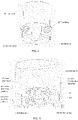
- valve assembly The main features of the valve assembly, best seen in Figs. 1A and 1B , will be briefly described first, and the individual parts are then shown and described in more detail with reference to the other drawings.
- the valve assembly comprises two valve elements, namely a main ball element 14 rotatably mounted within the manifold 3 and a core valve element 21 rotatably mounted within the main ball element 14.
- the main ball element 14 is provided with flow channels through its walls, each channel defined from an outer opening 40 to an inner opening.
- the main ball shaft has four outer openings 40 spaced around its outer circumference. The outer openings 40 are arranged such that they are in fluid flow communication with the openings 30 of the manifold 3, and hence the fittings 4 and the system fluid flow conduits, at a given rotational position of the main ball element with respect to the manifold.
- a first shaft 11 is provided to rotate with the main ball element 14. The first shaft extends from the main ball element into the top cover 1.
- the main ball element 14 defines an interior space 140 and, in the example shown, the interior space is closed by a cover 141 from which the first shaft 11 extends.
- a second valve element 21 Located within the interior space, and arranged to rotate relative to the main ball element 14 is a second valve element 21.
- a second shaft 7 extends from, and rotates with the second valve element and, in the example shown, the second shaft 7 extends through the first shaft (the first shaft 11 being hollow) into the top cover 1.
- the second valve element 21 is also provided with openings 210 that lead into channels through the second valve element and can align with ones or combinations of the openings 40 in the main ball element 14 depending on the relative rotational positions of the second valve element 21 and the main ball element 14.
- Various seals are provided as will be described further below.
- valve arrangement is also provided with two sets of microswitches to detect the rotational positions of the main ball element 14 and the second valve element 21, as will be described further below.
- An example of the microswitch features can be seen in Fig. 3 .
- a first set of microswitches (at least three microswitches in the set) is arranged to detect rotational position of one of the first and second shafts 11, 7 and, thus, of the valve element (and its ports or openings) associated with that shaft, and a second set of microswitches is arranged to detect rotational position of the other of the first and second shafts and its associated valve element and ports/openings.
- the first shaft 11, that rotates with the main ball element 14 forms a hollow outer shaft and the second shaft 7, arranged to rotate with the second valve element 21, is a solid (or hollow) shaft that extends through, and beyond, the first shaft 11 extending further into the top cover 1 than the first shaft.
- a lower set of microswitches 61 is arranged (here on a lower platform 9 within the top cover 1, secured by locking pins 51) proximate the part of the first shaft 11 extending into the top cover 1 to detect rotational position of that shaft, and an upper set of microswitches 6 is arranged (here on an upper platform 8 within the top cover 1, secured by locking pins 5) proximate the part of the second shaft 7 that protrudes from the first shaft 11 to detect rotational position of the second shaft 7.
- the two mounting platforms 8, 9 may be held at an axial distance from each other in the top cover by means of a reinforcing ring 10.
- first and second shafts are interchanged and/or that the sets of microswitches are mounted in different ways to be proximate the respective shafts.
- the microswitches detect rotational position of the shafts in a known manner by opening/closing a circuit dependent on the relative position of a cam formed on the respective shaft and contact between the cam and the switches.
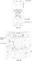
- the switch assemblies are shown in more detail in Figs. 7A and 7B . The actual operation of the cam switches, though, is a known technique and will not be described further here.
- the respective positions of the two valve elements can be determined and also controlled as required to direct the fluid flow in different directions and flow paths through the valve assembly.
- valve assembly As briefly described above, the integral assembly of two independent valve elements 14, 21, that are able to rotate relative to each other or with each other, and relative to the manifold ports, allows a variety of different flow paths to be provided through the valve assembly. It is envisaged that the relative positions of the valve elements could be set before installation of the valve assembly into the system, according to system requirements or, alternatively, that the valve assembly can be installed such that the relative positions of the valve elements can be controlled after installation, during use.
- FIG 4 shows, in greater detail, an example of a main ball element 14 as the first valve element.
- the ball element 14 has a circular cylindrical body through which channels are formed from openings 40 in the body.
- the body is annular and defines an interior space that is not seen in Fig. 4 . This is closed by a cover 141.
- a first shaft 11 is an integral part of the cover 141 and extends from the ball element 14.
- the first shaft is hollow, defining a passage 142 through which the second shaft can extend as described further below.
- the main ball element 14 is fitted inside the manifold 3 and O-ring seals 12, 15 are located in grooves 13 in the ball element body to seal the element inside the manifold 3.
- the ball element 14 is assembled such as to be able to rotate relative to the manifold.
- Fig. 4 also shows the fittings 2 that connect the openings or ports 30 of the manifold 3 to conduits in the systems from which fluid flows to the valve or to which fluid flows from the valve.
- the fittings include a connector piece 20, and may include various seals (16, 17) and washers (19) and bushings (18) and end with a seal for providing fluid tight engagement with the openings 40 of the ball element 14, via the manifold openings 30, when the ball element 14 is assembled inside the manifold 3 and rotated to a position where the ball element openings 14 align with the manifold openings/ports 30. In this aligned position, fluid in the system can flow through the valve assembly via the main ball element.
- FIG. 5 shows more details of the second valve element 21 that, in use, is assembled in the interior space of the main ball element 14 (the ball element is not shown in Fig. 5 to aid in explaining the structure of the second valve element).
- the second valve element comprises a core having three ports 210 leading to flow channels through the core.
- the core is arranged to rotate within and relative to the ball element 14 such that the alignment of the ports or openings 210 and the openings/ports of the ball element depends on the relative rotational positions of the valve elements.
- Seals 22 are provided and may be fitted into grooves 28 formed around the openings 210.
- the relative axial position of the second valve element 21 with respect to the body of the ball element 14 is controlled in this example by means of a compression spring 24 and a pressing disk 23 compressed between the second valve element core and the bottom cover 4 of the assembly.
- Means are provided to allow rotation of the second valve element 21 relative to the first valve element. In one example, this is by means of a solenoid 26, 27 comprising an electric winding 26 and a core 27. A ring 25 may be provided to maintain coaxiality of the solenoid parts 26, 27. Other brake or locking mechanisms may also be used.
- Figs. 8A and 8A show how the two valve elements 14, 21 are either locked against relative rotation or permitted to rotate relative to each other. In the example shown, this function is provided by the solenoid as described below.
- the solenoid which comprises an electric coil 26 around a ferromagnetic core 27, is activated when current is applied to the coil. As current flows through the coil, a magnetic field is created around the coil, the strength of which depends on the current, the number of windings and the core material. As a result of the magnetic field, the core 27 is pulled towards the centre of the coil 26 and remains in that position so long as current is flowing through the coil. This creates a gap 29 while the solenoid is activated between the pressing disk 23 and the core 21 and also between the pressing disk and the ball element 14 ( Fig. 8A ). This means that both valve elements 14, 21 are free to rotate about their axes relative to each other. If current stops, the solenoid is deactivated.
- Figures 9A to 9F show possible configurations and flow paths through the valve assembly when the valve is operating as a two-way valve, with the arrows showing the direction of fluid flow for different positions of the second valve element 21 relative to the main ball element 14.
- the ball element 14 is aligned with the manifold ports such that fluid enters the ball element at port A and port C of the ball element is connected to the other line or the system.
- the second valve element 21 is rotated relative to the ball element such that its opposing ports are aligned with port A and C respectively and fluid flows from port A directly through the valve to port C.
- Fig. 9A the ball element 14 is aligned with the manifold ports such that fluid enters the ball element at port A and port C of the ball element is connected to the other line or the system.
- the second valve element 21 is rotated relative to the ball element such that its opposing ports are aligned with port A and C respectively and fluid flows from port A directly through the valve to port C.
- the ball element is connected to fluid lines of the system at ports A and B and the second valve element is rotated by 90 degrees relative to Fig. 9A such that a fluid flow path is formed between port A and port B.
- the two elements are configured to provide flow from port B to port C.
- the two elements are configured to provide flow from port B to port D.
- the two elements are configured to provide flow from port D to port A.
- the two elements are configured to provide flow from port C to port D.
- the assembly is acting as a two-way valve in that fluid flows into one port and out of one other port.
- a two-way valve The purpose of a two-way valve is to shut of water flow or to allow (and regulate) flow through a pipe.
- one opening of the ball element is blind so that one of the three ports of the second valve element will be blocked by the body of the ball element so that the flow pattern is that of a two-way valve but various flow paths are possible depending on the rotational positions of the two elements relative to each other and relative to the manifold.
- Figures 10A to 10F show example configurations of the assembly working as a three-way valve.
- all three openings of the second valve element can be in alignment and fluid flow connection with ports of the ball element due to relative rotation of the two valve elements.
- valve elements are arranged such that fluid flows into port A and out at ports B and C.
- fluid flows in through port D and out through ports A and B.
- fluid flows in through port B and out from ports C and D.
- fluid flows into port C and out from ports A and D.
- the assembly has one inlet and two outlets, but the assembly could, instead, have two inlets and one outlet, operating as a mixing assembly.
- Control of the flow configuration of the valve assembly can be performed in two steps.
- a first step the two valve elements 14, 21 may be locked together by deactivating the solenoid (or by some other locking means) and the assembly is rotated e.g. by a dc motor (not shown) to align the ball element ports 40 with the appropriate manifold ports depending on the system lines to be connected to the valve.
- a dc motor not shown
- only this step is performed - i.e. the relative positions of the two valve elements are set before installation and then the entire assembly is rotated together to align with the appropriate manifold ports.
- the solenoid can be controlled to allow relative rotation of the second valve element to vary the configuration of the flow paths.
- Rotation of the valve elements either together or individually may be controlled by a motor control unit (not shown) based on control from the positions of the microswitches.
- the first, outer ball, valve element 14 has three ports A, B, C for connection to fluid lines of the system with a fourth port being closed.
- the second, inner core, valve element 21 has three ports A', B', C'.
- Four possible valve positions are possible and are defined in the matrix of Fig. 11A and shown schematically in Fig. 11B .
- port A' is aligned with port A
- port B' is aligned with port B
- port C is aligned with port C'.
- the second valve element 21 is rotated anti-clockwise relative to the first valve element 14 by a quarter turn such that port B' is aligned with port A, and port C' is aligned with port B.
- Port A' is closed off.
- a further quarter turn in the anti-clockwise direction brings the valve assembly to position 3 in which port C' is aligned with port A and port A' is aligned with port C. Port B is closed off.
- a further quarter turn rotation of the second valve element brings the assembly into position 4 in which port A' is aligned with port B and port B' is aligned with port C. Port C' is closed off.
- the valve assembly can be controlled to take up the desired configuration/position in different ways.
- a valve control algorithm is described with reference to Fig. 12 .
- the two valve elements 14,21 are set relative to each other as a first step and then the two elements are locked with respect to each other as described above and the combined valve assembly is rotated to the correct position.
- the method involves reading a configuration command e.g. port A' aligned with port A, port B' aligned with port B and port C' aligned with port C. It is then, 102, determined whether the relative positions of the two valve elements is correct for the commanded configuration.
- the second (inner) valve element 21 is rotated relative to the first (outer) valve element at step 104 until it is determined that the relative configuration of the valve elements is correct. Then, the position command for the entire valve assembly is read, 106, and it is determined, 108, whether the valve assembly is in the correct position (with respect to the manifold ports). If not, the entire valve assembly (i.e. the first and second valve elements together) is rotated relative to the manifold or housing to align with the correct system ports/lines.
- the valve assembly is installed and then controlled in situ.
- the algorithm can be implemented using simple logic whereby signals from position sensors indicating the positions of the two valve elements are compared with the connection matric.
- Such an algorithm is shown in Fig. 12 .
- the command is read from the port connection matrix ( Fig. 11A ).
- a rotation counter for the inner element 21 is set to 0, 210, and a determination is made as to whether the port connection is correct, 212, based on the position sensors. If not, the second (inner) valve member 21 is rotated by a quarter turn to its next position, 214 and the inner element rotation counter is increased to 1 and it is again checked, 212, whether the port correction is correct.
- the inner valve element is further rotated and the counter is set to 2.
- the first (outer) valve element is rotated to its next position, 218.
- the counter for the inner valve element 21 is reset to 0, 220, and up to four rotational positions for the inner valve element can be tried for the outer element in its new position. This continues until the correct connection configuration is obtained.
- Figure 14 shows an alternative algorithm, similar to that of Figure 13 , but which is implement using a valve motor control unit.
- a method can result in a quicker configuration of the valve assembly to the desired position.
- the command is read from the port connection matrix ( Fig. 11A ) and a determination is made at 310 as to whether the configuration of the assembly is correct. If not, the correct configuration is defined by the motor control unit, 312, and the correct position of the valve assembly relative to the system is defined at 314.
- the control unit calculates the shortest rotation of the first and second valve elements 14, 21 relative to each other and relative to the manifold to achieve the correct position, at 316.
- the valve elements and the assembly are then rotated accordingly, at 318.
- this assembly provides a two-way or a three-way valve, as required, from a single valve unit, with multiple flow path configurations.
- the design also means that if one port/pipe etc. fails, the valve can be reconfigured to use other operational ports/pipes etc.
- valve could be used to connect multiple small water tanks rather than only a single larger tank. This may be useful where space is limited or where mass distribution is desirable, such as in aircraft water systems.
- the compact and integral assembly design also minimises the water gaps in the assembly and thus limits the risk of water gathering in those gaps and freezing, or of debris accumulating.
- valve assembly design lends itself to additive manufacture which is simpler, quicker and less expensive and allows lighter components to be manufactured than in the case of conventional machining.
Landscapes
- Engineering & Computer Science (AREA)
- General Engineering & Computer Science (AREA)
- Mechanical Engineering (AREA)
- Multiple-Way Valves (AREA)
Abstract
Description
- The present disclosure is concerned with valve assemblies for regulating fluid flow through a fluid system.
- Valves are used in many applications to control the flow of fluid. Valves can be used to stop fluid flow or to reduce/increase and/or divert fluid flow. Valves can be manually operated and/or automatically operated e.g. motorised. For example, a valve may be provided between a source of fluid e.g. water and a reservoir such as a water tank e.g. for use in a water closet, a wash basin, a drinks machine etc. The valve can be opened to fill the reservoir from the source and then closed when the reservoir is sufficiently full. One type of valve is a ball valve or ball shaft wherein a rotatable ball element is mounted within a conduit providing the fluid flow path. The ball element has a passage or channel therethrough. The ball is mounted on a shaft that is rotated, in the case of manual operation, by means of a handle attached to the shaft or, in the case of a motor driven valve, by means of a motor. Rotation of the shaft causes rotation of the ball element and thus the channel relative to the flow path through the conduit. Thus, the valve is rotated, either manually by means of a handle or automatically, by means of a motor, between an open position in which the channel through the ball is aligned with the flow path to allow flow of fluid through the passage, and a closed position in which the passage is not aligned with the flow path and, instead, the body of the ball element closes off the flow path and fluid is unable to flow past the ball element.
- Some valves are two-way valves i.e. include a single channel with two ends, each of which cooperates with a port and a conduit of the system when in the open position and, when in the closed position, the channel ends do not align with the ports and conduits and so the body of the valve blocks flow of the fluid through the valve.
- Other valves may be three-way valves having a channel configuration such as a Tor L-shaped channel defining three inlets/outlets for alignment with three ports and fluid conduits by a quarter turn of the valve. Such valves may be used e.g. to divert a portion of the fluid flow from the main flow channel.
- A system designer will need to select and install the correct type of valve for the particular system and application and will select from available two-way and three way valves when designing the system. If a system requires both types of valves, multiple valves will be installed.
- Whilst such valve flow design is well-known, it does not offer flexibility in e.g. adding additional fluid supplies or applications after the valves have been selected and installed into the system, Furthermore, the use of multiple valves adds to the overall size, weight and cost of a system. This may be undesirable especially in applications where weight and/or size should be kept to a minimum e.g. in aircraft.
- There is, therefore a need for a simple, low cost, small and low weight valve assembly that can provide design flexibility.
- According to the disclosure, there is provided a multi-way valve assembly comprising: a valve housing having a plurality of fluid ports; a first valve member having one or more first flow channels defined therethrough and a first shaft, rotation of which causes rotation of the first valve member relative to the housing, the first valve member defining a cavity; a second valve member arranged within the cavity of the first valve member and having one or more second flow channels defined therethrough and a second shaft, rotation of which causes rotation of the second valve member relative to the housing; and a locking mechanism configured to, in a locked position, cause the second valve member to rotate with the first valve member relative to the housing and, in an unlocked position, to permit the second valve member to rotate relative to the first valve member and the housing
- Examples of the valve assembly according to the disclosure will now be described by way of example only with reference to the drawings.
-
Figure 1A is an exploded top view of a valve assembly according to the disclosure. -
Figure 1B is an exploded bottom view of a valve assembly according to the disclosure. -
Figure 2 is a perspective view of the exterior of an assembly according to the disclosure. -
Figure 3 is a sectional view of the assembly ofFig. 2 . -
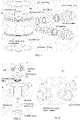
Figure 4 is an exploded view of a part of a valve assembly according to the disclosure. -
Figure 5 is an exploded view of another part of a valve assembly according to the disclosure. -
Figure 6 is an exploded view of another part of a valve assembly according to the disclosure. -
Figure 7A is an exploded view of a microswitch arrangement of a valve assembly according to the disclosure. -
Figure 7B is a more detailed view of the microswitches shown inFig. 7A . -
Figure 8A is a sectional view through a valve assembly according to the disclosure in a first state once the solenoid is activated. -
Figure 8B is a sectional view through a valve assembly according to the disclosure in a second state once the solenoid is deactivated. -
Figures 9A to 9F show possible positions of the assembly operating as a two-way valve. -
Figures 10A to 10F show possible positions of the assembly operating as a three-way valve. -
Figure 11A shows possible valve configurations in matrix form. -
Figure 11B shows possible configurations in schematic view, corresponding to the matrix configurations ofFig. 11A . -
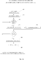
Figure 12 is a flow chart of one control method for the valve assembly. -
Figure 13 is a flow chart of an alternative control method for the valve assembly. -
Figure 14 is a flow chart of another alternative control method. - The valve assembly of the present disclosure includes two relatively rotatable valve elements configured such that a number of different flow paths can be created through the valve, allowing the assembly to selectively operate as a two-way or a three-way valve. The assembly allows more fluid conduits to be connected to the valve as desired. For example, in a water system, the single valve assembly can be configured to be connected to multiple water tanks or reservoirs.
- The assembly, will be described in more detail below with reference to specific examples, as shown in the drawings.
- Referring first to
Fig. 2 , the valve assembly is provided in a housing comprising atop cover 1, amanifold 3 for attachment to the fluid flow conduits of the fluid system, and abottom cover 4. The valve components are provided inside the housing as will be described further below whereby the valve elements are arranged inside themanifold 3 such that conduits of other parts of the system can be connected in fluid flow connection with the flow channels of the valve elements viafittings 2 throughopenings 30 in themanifold 3. Thefittings 2 may be fitted to the manifold by cooperating threads in theopenings 30 and on thefittings 2. In this example, the manifold is provided with four openings and four fittings for connection to four different fluid flow conduits of the system. Examples may be envisaged with different numbers of openings and fittings according to system design and requirements. - The main features of the valve assembly, best seen in
Figs. 1A and1B , will be briefly described first, and the individual parts are then shown and described in more detail with reference to the other drawings. - The valve assembly comprises two valve elements, namely a
main ball element 14 rotatably mounted within themanifold 3 and acore valve element 21 rotatably mounted within themain ball element 14. Themain ball element 14 is provided with flow channels through its walls, each channel defined from anouter opening 40 to an inner opening. In the example, the main ball shaft has fourouter openings 40 spaced around its outer circumference. Theouter openings 40 are arranged such that they are in fluid flow communication with theopenings 30 of themanifold 3, and hence thefittings 4 and the system fluid flow conduits, at a given rotational position of the main ball element with respect to the manifold. Afirst shaft 11 is provided to rotate with themain ball element 14. The first shaft extends from the main ball element into thetop cover 1. - The
main ball element 14 defines aninterior space 140 and, in the example shown, the interior space is closed by acover 141 from which thefirst shaft 11 extends. - Located within the interior space, and arranged to rotate relative to the
main ball element 14 is asecond valve element 21. Asecond shaft 7 extends from, and rotates with the second valve element and, in the example shown, thesecond shaft 7 extends through the first shaft (thefirst shaft 11 being hollow) into thetop cover 1. Thesecond valve element 21 is also provided withopenings 210 that lead into channels through the second valve element and can align with ones or combinations of theopenings 40 in themain ball element 14 depending on the relative rotational positions of thesecond valve element 21 and themain ball element 14. Various seals are provided as will be described further below. - In the example, the valve arrangement is also provided with two sets of microswitches to detect the rotational positions of the
main ball element 14 and thesecond valve element 21, as will be described further below. An example of the microswitch features can be seen inFig. 3 . A first set of microswitches (at least three microswitches in the set) is arranged to detect rotational position of one of the first andsecond shafts first shaft 11, that rotates with themain ball element 14 forms a hollow outer shaft and thesecond shaft 7, arranged to rotate with thesecond valve element 21, is a solid (or hollow) shaft that extends through, and beyond, thefirst shaft 11 extending further into thetop cover 1 than the first shaft. This allows rotational position of the two shafts (and hence the twovalve elements 14, 21) to be detected by two different microswitch assemblies positioned at different axial locations within thetop cover 1. A lower set ofmicroswitches 61 is arranged (here on alower platform 9 within thetop cover 1, secured by locking pins 51) proximate the part of thefirst shaft 11 extending into thetop cover 1 to detect rotational position of that shaft, and an upper set ofmicroswitches 6 is arranged (here on anupper platform 8 within thetop cover 1, secured by locking pins 5) proximate the part of thesecond shaft 7 that protrudes from thefirst shaft 11 to detect rotational position of thesecond shaft 7. The twomounting platforms ring 10. Other examples can be envisaged in which the first and second shafts are interchanged and/or that the sets of microswitches are mounted in different ways to be proximate the respective shafts. The microswitches detect rotational position of the shafts in a known manner by opening/closing a circuit dependent on the relative position of a cam formed on the respective shaft and contact between the cam and the switches. The switch assemblies are shown in more detail inFigs. 7A and 7B . The actual operation of the cam switches, though, is a known technique and will not be described further here. Using the two sets of microswitches, the respective positions of the two valve elements can be determined and also controlled as required to direct the fluid flow in different directions and flow paths through the valve assembly. - As briefly described above, the integral assembly of two
independent valve elements -
Figure 4 shows, in greater detail, an example of amain ball element 14 as the first valve element. Theball element 14 has a circular cylindrical body through which channels are formed fromopenings 40 in the body. The body is annular and defines an interior space that is not seen inFig. 4 . This is closed by acover 141. Afirst shaft 11 is an integral part of thecover 141 and extends from theball element 14. Here, the first shaft is hollow, defining apassage 142 through which the second shaft can extend as described further below. - The
main ball element 14 is fitted inside themanifold 3 and O-ring seals manifold 3. Theball element 14 is assembled such as to be able to rotate relative to the manifold.Fig. 4 also shows thefittings 2 that connect the openings orports 30 of themanifold 3 to conduits in the systems from which fluid flows to the valve or to which fluid flows from the valve. The fittings include aconnector piece 20, and may include various seals (16, 17) and washers (19) and bushings (18) and end with a seal for providing fluid tight engagement with theopenings 40 of theball element 14, via themanifold openings 30, when theball element 14 is assembled inside themanifold 3 and rotated to a position where theball element openings 14 align with the manifold openings/ports 30. In this aligned position, fluid in the system can flow through the valve assembly via the main ball element. -
Figure 5 shows more details of thesecond valve element 21 that, in use, is assembled in the interior space of the main ball element 14 (the ball element is not shown inFig. 5 to aid in explaining the structure of the second valve element). The second valve element comprises a core having threeports 210 leading to flow channels through the core. The core is arranged to rotate within and relative to theball element 14 such that the alignment of the ports oropenings 210 and the openings/ports of the ball element depends on the relative rotational positions of the valve elements.Seals 22 are provided and may be fitted into grooves 28 formed around theopenings 210. - The relative axial position of the
second valve element 21 with respect to the body of theball element 14 is controlled in this example by means of acompression spring 24 and apressing disk 23 compressed between the second valve element core and thebottom cover 4 of the assembly. - Means are provided to allow rotation of the
second valve element 21 relative to the first valve element. In one example, this is by means of asolenoid core 27. Aring 25 may be provided to maintain coaxiality of thesolenoid parts - Operation of the valve will now be described in more detail with reference to
Figs 8 to 10 .Figs. 8A and 8A show how the twovalve elements - The solenoid, which comprises an
electric coil 26 around aferromagnetic core 27, is activated when current is applied to the coil. As current flows through the coil, a magnetic field is created around the coil, the strength of which depends on the current, the number of windings and the core material. As a result of the magnetic field, thecore 27 is pulled towards the centre of thecoil 26 and remains in that position so long as current is flowing through the coil. This creates agap 29 while the solenoid is activated between thepressing disk 23 and thecore 21 and also between the pressing disk and the ball element 14 (Fig. 8A ). This means that bothvalve elements compression spring 24 forces thesolenoid core 27 and, consequently thepressure disk 23 into engagement with thevalve elements -
Figures 9A to 9F show possible configurations and flow paths through the valve assembly when the valve is operating as a two-way valve, with the arrows showing the direction of fluid flow for different positions of thesecond valve element 21 relative to themain ball element 14. In the position shown inFig. 9A theball element 14 is aligned with the manifold ports such that fluid enters the ball element at port A and port C of the ball element is connected to the other line or the system. Thesecond valve element 21 is rotated relative to the ball element such that its opposing ports are aligned with port A and C respectively and fluid flows from port A directly through the valve to port C. InFig. 9B , the ball element is connected to fluid lines of the system at ports A and B and the second valve element is rotated by 90 degrees relative toFig. 9A such that a fluid flow path is formed between port A and port B. In the arrangement ofFig. 9C , the two elements are configured to provide flow from port B to port C. In the arrangement ofFig. 9D , the two elements are configured to provide flow from port B to port D. In the arrangement ofFig. 9E , the two elements are configured to provide flow from port D to port A. In the arrangement ofFig. 9F , the two elements are configured to provide flow from port C to port D. In each configuration, the assembly is acting as a two-way valve in that fluid flows into one port and out of one other port. The purpose of a two-way valve is to shut of water flow or to allow (and regulate) flow through a pipe. In these configurations, one opening of the ball element is blind so that one of the three ports of the second valve element will be blocked by the body of the ball element so that the flow pattern is that of a two-way valve but various flow paths are possible depending on the rotational positions of the two elements relative to each other and relative to the manifold. -
Figures 10A to 10F show example configurations of the assembly working as a three-way valve. Here, all three openings of the second valve element can be in alignment and fluid flow connection with ports of the ball element due to relative rotation of the two valve elements. - In
Fig. 10A , the valve elements are arranged such that fluid flows into port A and out at ports B and C. InFig. 10B , fluid flows in through port D and out through ports A and B. In the configuration ofFig. 10C , fluid flows in through port B and out from ports C and D. In the configuration ofFig. 10D , fluid flows into port C and out from ports A and D. In all of the examples shown, the assembly has one inlet and two outlets, but the assembly could, instead, have two inlets and one outlet, operating as a mixing assembly. - Control of the flow configuration of the valve assembly can be performed in two steps. In a first step, the two
valve elements ball element ports 40 with the appropriate manifold ports depending on the system lines to be connected to the valve. In some embodiments of the disclosure, only this step is performed - i.e. the relative positions of the two valve elements are set before installation and then the entire assembly is rotated together to align with the appropriate manifold ports. - As mentioned above, however, in some embodiments, after the assembly has been installed, the solenoid can be controlled to allow relative rotation of the second valve element to vary the configuration of the flow paths. Rotation of the valve elements, either together or individually may be controlled by a motor control unit (not shown) based on control from the positions of the microswitches.
- Possible control algorithms for positioning the valve elements are described below with reference to
Figs. 11 to 14 . - In the example shown, the first, outer ball,
valve element 14 has three ports A, B, C for connection to fluid lines of the system with a fourth port being closed. The second, inner core,valve element 21 has three ports A', B', C'. Four possible valve positions are possible and are defined in the matrix ofFig. 11A and shown schematically inFig. 11B . Inposition 1, port A' is aligned with port A, port B' is aligned with port B and port C is aligned with port C'. For desiredposition 2, thesecond valve element 21 is rotated anti-clockwise relative to thefirst valve element 14 by a quarter turn such that port B' is aligned with port A, and port C' is aligned with port B. Port A' is closed off. A further quarter turn in the anti-clockwise direction brings the valve assembly toposition 3 in which port C' is aligned with port A and port A' is aligned with port C. Port B is closed off. A further quarter turn rotation of the second valve element brings the assembly intoposition 4 in which port A' is aligned with port B and port B' is aligned with port C. Port C' is closed off. - The valve assembly can be controlled to take up the desired configuration/position in different ways. One example of a valve control algorithm is described with reference to
Fig. 12 . In this example, the twovalve elements valve element 21 is rotated relative to the first (outer) valve element atstep 104 until it is determined that the relative configuration of the valve elements is correct. Then, the position command for the entire valve assembly is read, 106, and it is determined, 108, whether the valve assembly is in the correct position (with respect to the manifold ports). If not, the entire valve assembly (i.e. the first and second valve elements together) is rotated relative to the manifold or housing to align with the correct system ports/lines. - In an alternative method, the valve assembly is installed and then controlled in situ. In one example, the algorithm can be implemented using simple logic whereby signals from position sensors indicating the positions of the two valve elements are compared with the connection matric. Such an algorithm is shown in
Fig. 12 . Instep 200 the command is read from the port connection matrix (Fig. 11A ). A rotation counter for theinner element 21 is set to 0, 210, and a determination is made as to whether the port connection is correct, 212, based on the position sensors. If not, the second (inner)valve member 21 is rotated by a quarter turn to its next position, 214 and the inner element rotation counter is increased to 1 and it is again checked, 212, whether the port correction is correct. If not, the inner valve element is further rotated and the counter is set to 2. Once the counter has reached 4 - i.e. the inner valve element has been rotated to all four possible positions relative to the first, outer, valve element and the correct port connection has still not been achieved, then the first (outer) valve element is rotated to its next position, 218. The counter for theinner valve element 21 is reset to 0, 220, and up to four rotational positions for the inner valve element can be tried for the outer element in its new position. This continues until the correct connection configuration is obtained. -
Figure 14 shows an alternative algorithm, similar to that ofFigure 13 , but which is implement using a valve motor control unit. Such a method can result in a quicker configuration of the valve assembly to the desired position. Here, as with the method ofFig. 13 , first, 300, the command is read from the port connection matrix (Fig. 11A ) and a determination is made at 310 as to whether the configuration of the assembly is correct. If not, the correct configuration is defined by the motor control unit, 312, and the correct position of the valve assembly relative to the system is defined at 314. The control unit calculates the shortest rotation of the first andsecond valve elements
It can be seen, therefore, that this assembly provides a two-way or a three-way valve, as required, from a single valve unit, with multiple flow path configurations. The design also means that if one port/pipe etc. fails, the valve can be reconfigured to use other operational ports/pipes etc. - Because of the multiple configurations, the valve could be used to connect multiple small water tanks rather than only a single larger tank. This may be useful where space is limited or where mass distribution is desirable, such as in aircraft water systems.
- With the assembly of the disclosure, it is possible to achieve full shut-off even with a directional valve, which is not possible with conventional directional valves.
- The compact and integral assembly design also minimises the water gaps in the assembly and thus limits the risk of water gathering in those gaps and freezing, or of debris accumulating.
- The valve assembly design lends itself to additive manufacture which is simpler, quicker and less expensive and allows lighter components to be manufactured than in the case of conventional machining.
Claims (13)
- A multi-way valve assembly comprising:a valve housing (3) having a plurality of fluid ports (30);a first valve member (14) having one or more first flow channels defined therethrough and a first shaft (11), rotation of which causes rotation of the first valve member relative to the housing, the first valve member defining a cavity;a second valve member (21) arranged within the cavity of the first valve member and having one or more second flow channels defined therethrough and a second shaft (7), rotation of which causes rotation of the second valve member relative to the housing;and a locking mechanism (23, 24, 26, 27) configured to, in a locked position, cause the second valve member to rotate with the first valve member relative to the housing and, in an unlocked position, to permit the second valve member to rotate relative to the first valve member and the housing.
- The assembly of claim 1, wherein the first valve member comprises a ball element (14) and the second valve member comprises a core element (21) located within the ball element.
- The assembly of claim 1 or 2, wherein the cavity is provided with a cover (141) from which the first shaft extends.
- The assembly of any preceding claim, wherein the first shaft is a hollow shaft and the second shaft extends through the first shaft.
- The assembly of any preceding claim, further comprising a first set of microswitches (61) arranged to detect the rotational position of the first shaft and a second set of microswitches (6) arranged to detect the rotational position of the second shaft.
- The assembly of claim 5, wherein the first set of microswitches is arranged on a first platform (9) within the housing at a first axial position and the second set of microswitches is arranged on a second platform (8) within the housing at a second axial position.
- The assembly of any preceding claim, wherein the first valve member comprises two flow channels each defined between a respective inlet port and outlet port formed in the valve member.
- The assembly of any preceding claim, wherein the second valve member includes a T-shaped fluid channel defined between three ports in the valve member.
- The assembly of any preceding claim, wherein the locking mechanism comprises a compression spring (24) and a pressing disk (23) compressed between the second valve member and the housing, and a drive to move the pressing disk with respect to the compression spring.
- The assembly of claim 9, wherein the drive comprises a solenoid (26, 27), and wherein activation of the solenoid the pressing disk is not in contact with the second valve member and the second valve member is able to rotate relative to the first valve member, and when the solenoid is deactivated, the pressing disk presses the second valve member into engagement with the first valve member such that rotation of the first valve member causes rotation of the second valve member.
- A fluid flow system comprising one or fluid flow lines and a valve assembly as claimed in any preceding claim located within one or more fluid flow lines.
- A water system comprising a water tank and a water supply and a fluid flow system as claim in claim 11 providing flow lines between the tank and the supply.
- The water system of claim 12, being an aircraft water system.
Priority Applications (2)
| Application Number | Priority Date | Filing Date | Title |
|---|---|---|---|
| EP21461565.0A EP4116612B1 (en) | 2021-07-07 | 2021-07-07 | Valve assembly |
| US17/852,638 US11796079B2 (en) | 2021-07-07 | 2022-06-29 | Valve assembly |
Applications Claiming Priority (1)
| Application Number | Priority Date | Filing Date | Title |
|---|---|---|---|
| EP21461565.0A EP4116612B1 (en) | 2021-07-07 | 2021-07-07 | Valve assembly |
Publications (2)
| Publication Number | Publication Date |
|---|---|
| EP4116612A1 true EP4116612A1 (en) | 2023-01-11 |
| EP4116612B1 EP4116612B1 (en) | 2024-04-17 |
Family
ID=76845180
Family Applications (1)
| Application Number | Title | Priority Date | Filing Date |
|---|---|---|---|
| EP21461565.0A Active EP4116612B1 (en) | 2021-07-07 | 2021-07-07 | Valve assembly |
Country Status (2)
| Country | Link |
|---|---|
| US (1) | US11796079B2 (en) |
| EP (1) | EP4116612B1 (en) |
Families Citing this family (1)
| Publication number | Priority date | Publication date | Assignee | Title |
|---|---|---|---|---|
| EP3940271B1 (en) * | 2020-07-17 | 2025-02-26 | Goodrich Corporation | Valve assembly with a position sensor assembly |
Citations (2)
| Publication number | Priority date | Publication date | Assignee | Title |
|---|---|---|---|---|
| JPS58174766A (en) * | 1982-04-05 | 1983-10-13 | Taimei Kinzoku Kogyo Kk | Flow adjusting ball valve |
| WO2017217112A1 (en) * | 2016-06-15 | 2017-12-21 | 株式会社デンソー | Switchable flow control valve |
Family Cites Families (4)
| Publication number | Priority date | Publication date | Assignee | Title |
|---|---|---|---|---|
| US2769456A (en) * | 1955-07-12 | 1956-11-06 | Roy L Atkinson | Combination plug valve and orifice housing |
| US8839817B2 (en) * | 2011-03-30 | 2014-09-23 | Schneider Electric Buildings, Llc | Valve with dual rotation valve member |
| WO2015072915A1 (en) | 2013-11-12 | 2015-05-21 | Ab Somas Ventiler | Ball member for a valve assembly, ball valve assembly having a ball member and method for controlling the temperature of a ball member |
| US11560827B2 (en) | 2019-08-15 | 2023-01-24 | Schaeffler Technologies AG & Co. KG | Rotary valve assembly for coolant control valve and coolant control valve with rotary valve assembly |
-
2021
- 2021-07-07 EP EP21461565.0A patent/EP4116612B1/en active Active
-
2022
- 2022-06-29 US US17/852,638 patent/US11796079B2/en active Active
Patent Citations (2)
| Publication number | Priority date | Publication date | Assignee | Title |
|---|---|---|---|---|
| JPS58174766A (en) * | 1982-04-05 | 1983-10-13 | Taimei Kinzoku Kogyo Kk | Flow adjusting ball valve |
| WO2017217112A1 (en) * | 2016-06-15 | 2017-12-21 | 株式会社デンソー | Switchable flow control valve |
Also Published As
| Publication number | Publication date |
|---|---|
| EP4116612B1 (en) | 2024-04-17 |
| US20230011853A1 (en) | 2023-01-12 |
| US11796079B2 (en) | 2023-10-24 |
Similar Documents
| Publication | Publication Date | Title |
|---|---|---|
| US5199458A (en) | Multi-way valve | |
| US6240941B1 (en) | Modular, interconnectable valve | |
| US20170108141A1 (en) | Rotary valve | |
| US5769124A (en) | Fresh water supply system for an aircraft | |
| US10745894B2 (en) | Universal embedded system for sanitary faucet components | |
| US11796079B2 (en) | Valve assembly | |
| CN102472397B (en) | Valve device and a steam turbine system incorporating said valve device | |
| US20210372099A1 (en) | Auxiliary valve for hydrant | |
| US20200248821A1 (en) | Multiple seat trim choke valve | |
| KR101165366B1 (en) | Dual ball valve for flow control | |
| US11473957B2 (en) | Meter bypass assembly having a housing including valve bodies rotationally fixed to opposing ends of a shaft | |
| US4951702A (en) | Bidet valve | |
| US20110057140A1 (en) | Modular spool valve | |
| CN219510182U (en) | Six-way valve and temperature control system | |
| EP3311048A1 (en) | A ball valve assembly | |
| US20170299072A1 (en) | Top Entry Ball Valve | |
| CN211145501U (en) | Modular valve system | |
| EP0240059A1 (en) | Balanced rotary valve | |
| US3257094A (en) | Valve | |
| CA3244559A1 (en) | Hydraulic rotary manifold | |
| JP5220364B2 (en) | Compound valve | |
| JP7746301B2 (en) | Double Shut-Off Valve | |
| KR20230026054A (en) | Double three way valve | |
| US20220154833A1 (en) | Multi-port rotary slide valve | |
| CN222102825U (en) | A quick-opening valve core and faucet |
Legal Events
| Date | Code | Title | Description |
|---|---|---|---|
| PUAI | Public reference made under article 153(3) epc to a published international application that has entered the european phase |
Free format text: ORIGINAL CODE: 0009012 |
|
| STAA | Information on the status of an ep patent application or granted ep patent |
Free format text: STATUS: THE APPLICATION HAS BEEN PUBLISHED |
|
| AK | Designated contracting states |
Kind code of ref document: A1 Designated state(s): AL AT BE BG CH CY CZ DE DK EE ES FI FR GB GR HR HU IE IS IT LI LT LU LV MC MK MT NL NO PL PT RO RS SE SI SK SM TR |
|
| STAA | Information on the status of an ep patent application or granted ep patent |
Free format text: STATUS: REQUEST FOR EXAMINATION WAS MADE |
|
| 17P | Request for examination filed |
Effective date: 20230711 |
|
| RBV | Designated contracting states (corrected) |
Designated state(s): AL AT BE BG CH CY CZ DE DK EE ES FI FR GB GR HR HU IE IS IT LI LT LU LV MC MK MT NL NO PL PT RO RS SE SI SK SM TR |
|
| P01 | Opt-out of the competence of the unified patent court (upc) registered |
Effective date: 20230922 |
|
| GRAP | Despatch of communication of intention to grant a patent |
Free format text: ORIGINAL CODE: EPIDOSNIGR1 |
|
| STAA | Information on the status of an ep patent application or granted ep patent |
Free format text: STATUS: GRANT OF PATENT IS INTENDED |
|
| INTG | Intention to grant announced |
Effective date: 20231201 |
|
| GRAS | Grant fee paid |
Free format text: ORIGINAL CODE: EPIDOSNIGR3 |
|
| GRAA | (expected) grant |
Free format text: ORIGINAL CODE: 0009210 |
|
| STAA | Information on the status of an ep patent application or granted ep patent |
Free format text: STATUS: THE PATENT HAS BEEN GRANTED |
|
| AK | Designated contracting states |
Kind code of ref document: B1 Designated state(s): AL AT BE BG CH CY CZ DE DK EE ES FI FR GB GR HR HU IE IS IT LI LT LU LV MC MK MT NL NO PL PT RO RS SE SI SK SM TR |
|
| REG | Reference to a national code |
Ref country code: GB Ref legal event code: FG4D |
|
| REG | Reference to a national code |
Ref country code: CH Ref legal event code: EP |
|
| REG | Reference to a national code |
Ref country code: IE Ref legal event code: FG4D Ref country code: DE Ref legal event code: R096 Ref document number: 602021011918 Country of ref document: DE |
|
| REG | Reference to a national code |
Ref country code: LT Ref legal event code: MG9D |
|
| REG | Reference to a national code |
Ref country code: NL Ref legal event code: MP Effective date: 20240417 |
|
| REG | Reference to a national code |
Ref country code: AT Ref legal event code: MK05 Ref document number: 1677544 Country of ref document: AT Kind code of ref document: T Effective date: 20240417 |
|
| PG25 | Lapsed in a contracting state [announced via postgrant information from national office to epo] |
Ref country code: NL Free format text: LAPSE BECAUSE OF FAILURE TO SUBMIT A TRANSLATION OF THE DESCRIPTION OR TO PAY THE FEE WITHIN THE PRESCRIBED TIME-LIMIT Effective date: 20240417 |
|
| PG25 | Lapsed in a contracting state [announced via postgrant information from national office to epo] |
Ref country code: NL Free format text: LAPSE BECAUSE OF FAILURE TO SUBMIT A TRANSLATION OF THE DESCRIPTION OR TO PAY THE FEE WITHIN THE PRESCRIBED TIME-LIMIT Effective date: 20240417 |
|
| PG25 | Lapsed in a contracting state [announced via postgrant information from national office to epo] |
Ref country code: IS Free format text: LAPSE BECAUSE OF FAILURE TO SUBMIT A TRANSLATION OF THE DESCRIPTION OR TO PAY THE FEE WITHIN THE PRESCRIBED TIME-LIMIT Effective date: 20240817 |
|
| PG25 | Lapsed in a contracting state [announced via postgrant information from national office to epo] |
Ref country code: BG Free format text: LAPSE BECAUSE OF FAILURE TO SUBMIT A TRANSLATION OF THE DESCRIPTION OR TO PAY THE FEE WITHIN THE PRESCRIBED TIME-LIMIT Effective date: 20240417 |
|
| PG25 | Lapsed in a contracting state [announced via postgrant information from national office to epo] |
Ref country code: FI Free format text: LAPSE BECAUSE OF FAILURE TO SUBMIT A TRANSLATION OF THE DESCRIPTION OR TO PAY THE FEE WITHIN THE PRESCRIBED TIME-LIMIT Effective date: 20240417 Ref country code: HR Free format text: LAPSE BECAUSE OF FAILURE TO SUBMIT A TRANSLATION OF THE DESCRIPTION OR TO PAY THE FEE WITHIN THE PRESCRIBED TIME-LIMIT Effective date: 20240417 |
|
| PG25 | Lapsed in a contracting state [announced via postgrant information from national office to epo] |
Ref country code: GR Free format text: LAPSE BECAUSE OF FAILURE TO SUBMIT A TRANSLATION OF THE DESCRIPTION OR TO PAY THE FEE WITHIN THE PRESCRIBED TIME-LIMIT Effective date: 20240718 |
|
| PG25 | Lapsed in a contracting state [announced via postgrant information from national office to epo] |
Ref country code: PT Free format text: LAPSE BECAUSE OF FAILURE TO SUBMIT A TRANSLATION OF THE DESCRIPTION OR TO PAY THE FEE WITHIN THE PRESCRIBED TIME-LIMIT Effective date: 20240819 |
|
| PG25 | Lapsed in a contracting state [announced via postgrant information from national office to epo] |
Ref country code: ES Free format text: LAPSE BECAUSE OF FAILURE TO SUBMIT A TRANSLATION OF THE DESCRIPTION OR TO PAY THE FEE WITHIN THE PRESCRIBED TIME-LIMIT Effective date: 20240417 |
|
| PG25 | Lapsed in a contracting state [announced via postgrant information from national office to epo] |
Ref country code: AT Free format text: LAPSE BECAUSE OF FAILURE TO SUBMIT A TRANSLATION OF THE DESCRIPTION OR TO PAY THE FEE WITHIN THE PRESCRIBED TIME-LIMIT Effective date: 20240417 |
|
| PG25 | Lapsed in a contracting state [announced via postgrant information from national office to epo] |
Ref country code: PL Free format text: LAPSE BECAUSE OF FAILURE TO SUBMIT A TRANSLATION OF THE DESCRIPTION OR TO PAY THE FEE WITHIN THE PRESCRIBED TIME-LIMIT Effective date: 20240417 |
|
| PG25 | Lapsed in a contracting state [announced via postgrant information from national office to epo] |
Ref country code: LV Free format text: LAPSE BECAUSE OF FAILURE TO SUBMIT A TRANSLATION OF THE DESCRIPTION OR TO PAY THE FEE WITHIN THE PRESCRIBED TIME-LIMIT Effective date: 20240417 |
|
| PG25 | Lapsed in a contracting state [announced via postgrant information from national office to epo] |
Ref country code: PT Free format text: LAPSE BECAUSE OF FAILURE TO SUBMIT A TRANSLATION OF THE DESCRIPTION OR TO PAY THE FEE WITHIN THE PRESCRIBED TIME-LIMIT Effective date: 20240819 Ref country code: PL Free format text: LAPSE BECAUSE OF FAILURE TO SUBMIT A TRANSLATION OF THE DESCRIPTION OR TO PAY THE FEE WITHIN THE PRESCRIBED TIME-LIMIT Effective date: 20240417 Ref country code: NO Free format text: LAPSE BECAUSE OF FAILURE TO SUBMIT A TRANSLATION OF THE DESCRIPTION OR TO PAY THE FEE WITHIN THE PRESCRIBED TIME-LIMIT Effective date: 20240717 Ref country code: LV Free format text: LAPSE BECAUSE OF FAILURE TO SUBMIT A TRANSLATION OF THE DESCRIPTION OR TO PAY THE FEE WITHIN THE PRESCRIBED TIME-LIMIT Effective date: 20240417 Ref country code: IS Free format text: LAPSE BECAUSE OF FAILURE TO SUBMIT A TRANSLATION OF THE DESCRIPTION OR TO PAY THE FEE WITHIN THE PRESCRIBED TIME-LIMIT Effective date: 20240817 Ref country code: HR Free format text: LAPSE BECAUSE OF FAILURE TO SUBMIT A TRANSLATION OF THE DESCRIPTION OR TO PAY THE FEE WITHIN THE PRESCRIBED TIME-LIMIT Effective date: 20240417 Ref country code: GR Free format text: LAPSE BECAUSE OF FAILURE TO SUBMIT A TRANSLATION OF THE DESCRIPTION OR TO PAY THE FEE WITHIN THE PRESCRIBED TIME-LIMIT Effective date: 20240718 Ref country code: FI Free format text: LAPSE BECAUSE OF FAILURE TO SUBMIT A TRANSLATION OF THE DESCRIPTION OR TO PAY THE FEE WITHIN THE PRESCRIBED TIME-LIMIT Effective date: 20240417 Ref country code: ES Free format text: LAPSE BECAUSE OF FAILURE TO SUBMIT A TRANSLATION OF THE DESCRIPTION OR TO PAY THE FEE WITHIN THE PRESCRIBED TIME-LIMIT Effective date: 20240417 Ref country code: BG Free format text: LAPSE BECAUSE OF FAILURE TO SUBMIT A TRANSLATION OF THE DESCRIPTION OR TO PAY THE FEE WITHIN THE PRESCRIBED TIME-LIMIT Effective date: 20240417 Ref country code: AT Free format text: LAPSE BECAUSE OF FAILURE TO SUBMIT A TRANSLATION OF THE DESCRIPTION OR TO PAY THE FEE WITHIN THE PRESCRIBED TIME-LIMIT Effective date: 20240417 Ref country code: RS Free format text: LAPSE BECAUSE OF FAILURE TO SUBMIT A TRANSLATION OF THE DESCRIPTION OR TO PAY THE FEE WITHIN THE PRESCRIBED TIME-LIMIT Effective date: 20240717 |
|
| PG25 | Lapsed in a contracting state [announced via postgrant information from national office to epo] |
Ref country code: DK Free format text: LAPSE BECAUSE OF FAILURE TO SUBMIT A TRANSLATION OF THE DESCRIPTION OR TO PAY THE FEE WITHIN THE PRESCRIBED TIME-LIMIT Effective date: 20240417 |
|
| REG | Reference to a national code |
Ref country code: DE Ref legal event code: R097 Ref document number: 602021011918 Country of ref document: DE |
|
| PG25 | Lapsed in a contracting state [announced via postgrant information from national office to epo] |
Ref country code: EE Free format text: LAPSE BECAUSE OF FAILURE TO SUBMIT A TRANSLATION OF THE DESCRIPTION OR TO PAY THE FEE WITHIN THE PRESCRIBED TIME-LIMIT Effective date: 20240417 |
|
| PG25 | Lapsed in a contracting state [announced via postgrant information from national office to epo] |
Ref country code: CZ Free format text: LAPSE BECAUSE OF FAILURE TO SUBMIT A TRANSLATION OF THE DESCRIPTION OR TO PAY THE FEE WITHIN THE PRESCRIBED TIME-LIMIT Effective date: 20240417 |
|
| PG25 | Lapsed in a contracting state [announced via postgrant information from national office to epo] |
Ref country code: RO Free format text: LAPSE BECAUSE OF FAILURE TO SUBMIT A TRANSLATION OF THE DESCRIPTION OR TO PAY THE FEE WITHIN THE PRESCRIBED TIME-LIMIT Effective date: 20240417 Ref country code: SK Free format text: LAPSE BECAUSE OF FAILURE TO SUBMIT A TRANSLATION OF THE DESCRIPTION OR TO PAY THE FEE WITHIN THE PRESCRIBED TIME-LIMIT Effective date: 20240417 |
|
| PG25 | Lapsed in a contracting state [announced via postgrant information from national office to epo] |
Ref country code: SM Free format text: LAPSE BECAUSE OF FAILURE TO SUBMIT A TRANSLATION OF THE DESCRIPTION OR TO PAY THE FEE WITHIN THE PRESCRIBED TIME-LIMIT Effective date: 20240417 |
|
| PG25 | Lapsed in a contracting state [announced via postgrant information from national office to epo] |
Ref country code: SM Free format text: LAPSE BECAUSE OF FAILURE TO SUBMIT A TRANSLATION OF THE DESCRIPTION OR TO PAY THE FEE WITHIN THE PRESCRIBED TIME-LIMIT Effective date: 20240417 Ref country code: SK Free format text: LAPSE BECAUSE OF FAILURE TO SUBMIT A TRANSLATION OF THE DESCRIPTION OR TO PAY THE FEE WITHIN THE PRESCRIBED TIME-LIMIT Effective date: 20240417 Ref country code: RO Free format text: LAPSE BECAUSE OF FAILURE TO SUBMIT A TRANSLATION OF THE DESCRIPTION OR TO PAY THE FEE WITHIN THE PRESCRIBED TIME-LIMIT Effective date: 20240417 Ref country code: EE Free format text: LAPSE BECAUSE OF FAILURE TO SUBMIT A TRANSLATION OF THE DESCRIPTION OR TO PAY THE FEE WITHIN THE PRESCRIBED TIME-LIMIT Effective date: 20240417 Ref country code: DK Free format text: LAPSE BECAUSE OF FAILURE TO SUBMIT A TRANSLATION OF THE DESCRIPTION OR TO PAY THE FEE WITHIN THE PRESCRIBED TIME-LIMIT Effective date: 20240417 Ref country code: CZ Free format text: LAPSE BECAUSE OF FAILURE TO SUBMIT A TRANSLATION OF THE DESCRIPTION OR TO PAY THE FEE WITHIN THE PRESCRIBED TIME-LIMIT Effective date: 20240417 |
|
| PG25 | Lapsed in a contracting state [announced via postgrant information from national office to epo] |
Ref country code: MC Free format text: LAPSE BECAUSE OF FAILURE TO SUBMIT A TRANSLATION OF THE DESCRIPTION OR TO PAY THE FEE WITHIN THE PRESCRIBED TIME-LIMIT Effective date: 20240417 Ref country code: IT Free format text: LAPSE BECAUSE OF FAILURE TO SUBMIT A TRANSLATION OF THE DESCRIPTION OR TO PAY THE FEE WITHIN THE PRESCRIBED TIME-LIMIT Effective date: 20240417 |
|
| PLBE | No opposition filed within time limit |
Free format text: ORIGINAL CODE: 0009261 |
|
| STAA | Information on the status of an ep patent application or granted ep patent |
Free format text: STATUS: NO OPPOSITION FILED WITHIN TIME LIMIT |
|
| REG | Reference to a national code |
Ref country code: CH Ref legal event code: PL |
|
| PG25 | Lapsed in a contracting state [announced via postgrant information from national office to epo] |
Ref country code: LU Free format text: LAPSE BECAUSE OF NON-PAYMENT OF DUE FEES Effective date: 20240707 |
|
| 26N | No opposition filed |
Effective date: 20250120 |
|
| PG25 | Lapsed in a contracting state [announced via postgrant information from national office to epo] |
Ref country code: LU Free format text: LAPSE BECAUSE OF NON-PAYMENT OF DUE FEES Effective date: 20240707 |
|
| PG25 | Lapsed in a contracting state [announced via postgrant information from national office to epo] |
Ref country code: SI Free format text: LAPSE BECAUSE OF FAILURE TO SUBMIT A TRANSLATION OF THE DESCRIPTION OR TO PAY THE FEE WITHIN THE PRESCRIBED TIME-LIMIT Effective date: 20240417 Ref country code: CH Free format text: LAPSE BECAUSE OF NON-PAYMENT OF DUE FEES Effective date: 20240731 Ref country code: BE Free format text: LAPSE BECAUSE OF NON-PAYMENT OF DUE FEES Effective date: 20240731 |
|
| REG | Reference to a national code |
Ref country code: BE Ref legal event code: MM Effective date: 20240731 |
|
| PGFP | Annual fee paid to national office [announced via postgrant information from national office to epo] |
Ref country code: GB Payment date: 20250619 Year of fee payment: 5 |
|
| PGFP | Annual fee paid to national office [announced via postgrant information from national office to epo] |
Ref country code: FR Payment date: 20250620 Year of fee payment: 5 |
|
| PG25 | Lapsed in a contracting state [announced via postgrant information from national office to epo] |
Ref country code: IE Free format text: LAPSE BECAUSE OF NON-PAYMENT OF DUE FEES Effective date: 20240707 |
|
| PG25 | Lapsed in a contracting state [announced via postgrant information from national office to epo] |
Ref country code: SE Free format text: LAPSE BECAUSE OF FAILURE TO SUBMIT A TRANSLATION OF THE DESCRIPTION OR TO PAY THE FEE WITHIN THE PRESCRIBED TIME-LIMIT Effective date: 20240417 |
|
| PGFP | Annual fee paid to national office [announced via postgrant information from national office to epo] |
Ref country code: DE Payment date: 20250620 Year of fee payment: 5 |
|
| PG25 | Lapsed in a contracting state [announced via postgrant information from national office to epo] |
Ref country code: CY Free format text: LAPSE BECAUSE OF FAILURE TO SUBMIT A TRANSLATION OF THE DESCRIPTION OR TO PAY THE FEE WITHIN THE PRESCRIBED TIME-LIMIT; INVALID AB INITIO Effective date: 20210707 |
|
| PG25 | Lapsed in a contracting state [announced via postgrant information from national office to epo] |
Ref country code: HU Free format text: LAPSE BECAUSE OF FAILURE TO SUBMIT A TRANSLATION OF THE DESCRIPTION OR TO PAY THE FEE WITHIN THE PRESCRIBED TIME-LIMIT; INVALID AB INITIO Effective date: 20210707 |