EP4116595A1 - Cage and roller - Google Patents
Cage and roller Download PDFInfo
- Publication number
- EP4116595A1 EP4116595A1 EP21764324.6A EP21764324A EP4116595A1 EP 4116595 A1 EP4116595 A1 EP 4116595A1 EP 21764324 A EP21764324 A EP 21764324A EP 4116595 A1 EP4116595 A1 EP 4116595A1
- Authority
- EP
- European Patent Office
- Prior art keywords
- rollers
- roller
- cage
- portions
- pair
- Prior art date
- Legal status (The legal status is an assumption and is not a legal conclusion. Google has not performed a legal analysis and makes no representation as to the accuracy of the status listed.)
- Withdrawn
Links
- 238000003780 insertion Methods 0.000 claims description 13
- 230000037431 insertion Effects 0.000 claims description 13
- 230000000149 penetrating effect Effects 0.000 claims description 3
- 229920005989 resin Polymers 0.000 claims description 2
- 239000011347 resin Substances 0.000 claims description 2
- 230000000694 effects Effects 0.000 description 6
- 230000002265 prevention Effects 0.000 description 4
- 230000004323 axial length Effects 0.000 description 3
- 230000005540 biological transmission Effects 0.000 description 3
- 229920003002 synthetic resin Polymers 0.000 description 3
- 239000000057 synthetic resin Substances 0.000 description 3
- 238000012986 modification Methods 0.000 description 2
- 230000004048 modification Effects 0.000 description 2
- 238000005096 rolling process Methods 0.000 description 2
- 239000000470 constituent Substances 0.000 description 1
- 230000005489 elastic deformation Effects 0.000 description 1
- 239000000446 fuel Substances 0.000 description 1
- 230000002452 interceptive effect Effects 0.000 description 1
- 239000002184 metal Substances 0.000 description 1
- 230000002093 peripheral effect Effects 0.000 description 1
Images



Classifications
-
- F—MECHANICAL ENGINEERING; LIGHTING; HEATING; WEAPONS; BLASTING
- F16—ENGINEERING ELEMENTS AND UNITS; GENERAL MEASURES FOR PRODUCING AND MAINTAINING EFFECTIVE FUNCTIONING OF MACHINES OR INSTALLATIONS; THERMAL INSULATION IN GENERAL
- F16C—SHAFTS; FLEXIBLE SHAFTS; ELEMENTS OR CRANKSHAFT MECHANISMS; ROTARY BODIES OTHER THAN GEARING ELEMENTS; BEARINGS
- F16C19/00—Bearings with rolling contact, for exclusively rotary movement
- F16C19/22—Bearings with rolling contact, for exclusively rotary movement with bearing rollers essentially of the same size in one or more circular rows, e.g. needle bearings
- F16C19/24—Bearings with rolling contact, for exclusively rotary movement with bearing rollers essentially of the same size in one or more circular rows, e.g. needle bearings for radial load mainly
- F16C19/26—Bearings with rolling contact, for exclusively rotary movement with bearing rollers essentially of the same size in one or more circular rows, e.g. needle bearings for radial load mainly with a single row of rollers
-
- F—MECHANICAL ENGINEERING; LIGHTING; HEATING; WEAPONS; BLASTING
- F16—ENGINEERING ELEMENTS AND UNITS; GENERAL MEASURES FOR PRODUCING AND MAINTAINING EFFECTIVE FUNCTIONING OF MACHINES OR INSTALLATIONS; THERMAL INSULATION IN GENERAL
- F16C—SHAFTS; FLEXIBLE SHAFTS; ELEMENTS OR CRANKSHAFT MECHANISMS; ROTARY BODIES OTHER THAN GEARING ELEMENTS; BEARINGS
- F16C19/00—Bearings with rolling contact, for exclusively rotary movement
- F16C19/22—Bearings with rolling contact, for exclusively rotary movement with bearing rollers essentially of the same size in one or more circular rows, e.g. needle bearings
- F16C19/24—Bearings with rolling contact, for exclusively rotary movement with bearing rollers essentially of the same size in one or more circular rows, e.g. needle bearings for radial load mainly
-
- F—MECHANICAL ENGINEERING; LIGHTING; HEATING; WEAPONS; BLASTING
- F16—ENGINEERING ELEMENTS AND UNITS; GENERAL MEASURES FOR PRODUCING AND MAINTAINING EFFECTIVE FUNCTIONING OF MACHINES OR INSTALLATIONS; THERMAL INSULATION IN GENERAL
- F16C—SHAFTS; FLEXIBLE SHAFTS; ELEMENTS OR CRANKSHAFT MECHANISMS; ROTARY BODIES OTHER THAN GEARING ELEMENTS; BEARINGS
- F16C19/00—Bearings with rolling contact, for exclusively rotary movement
- F16C19/22—Bearings with rolling contact, for exclusively rotary movement with bearing rollers essentially of the same size in one or more circular rows, e.g. needle bearings
- F16C19/44—Needle bearings
- F16C19/46—Needle bearings with one row or needles
- F16C19/463—Needle bearings with one row or needles consisting of needle rollers held in a cage, i.e. subunit without race rings
-
- F—MECHANICAL ENGINEERING; LIGHTING; HEATING; WEAPONS; BLASTING
- F16—ENGINEERING ELEMENTS AND UNITS; GENERAL MEASURES FOR PRODUCING AND MAINTAINING EFFECTIVE FUNCTIONING OF MACHINES OR INSTALLATIONS; THERMAL INSULATION IN GENERAL
- F16C—SHAFTS; FLEXIBLE SHAFTS; ELEMENTS OR CRANKSHAFT MECHANISMS; ROTARY BODIES OTHER THAN GEARING ELEMENTS; BEARINGS
- F16C19/00—Bearings with rolling contact, for exclusively rotary movement
- F16C19/22—Bearings with rolling contact, for exclusively rotary movement with bearing rollers essentially of the same size in one or more circular rows, e.g. needle bearings
- F16C19/44—Needle bearings
- F16C19/46—Needle bearings with one row or needles
- F16C19/466—Needle bearings with one row or needles comprising needle rollers and an outer ring, i.e. subunit without inner ring
-
- F—MECHANICAL ENGINEERING; LIGHTING; HEATING; WEAPONS; BLASTING
- F16—ENGINEERING ELEMENTS AND UNITS; GENERAL MEASURES FOR PRODUCING AND MAINTAINING EFFECTIVE FUNCTIONING OF MACHINES OR INSTALLATIONS; THERMAL INSULATION IN GENERAL
- F16C—SHAFTS; FLEXIBLE SHAFTS; ELEMENTS OR CRANKSHAFT MECHANISMS; ROTARY BODIES OTHER THAN GEARING ELEMENTS; BEARINGS
- F16C29/00—Bearings for parts moving only linearly
- F16C29/04—Ball or roller bearings
- F16C29/048—Ball or roller bearings with thin walled races, e.g. tracks of sheet metal
-
- F—MECHANICAL ENGINEERING; LIGHTING; HEATING; WEAPONS; BLASTING
- F16—ENGINEERING ELEMENTS AND UNITS; GENERAL MEASURES FOR PRODUCING AND MAINTAINING EFFECTIVE FUNCTIONING OF MACHINES OR INSTALLATIONS; THERMAL INSULATION IN GENERAL
- F16C—SHAFTS; FLEXIBLE SHAFTS; ELEMENTS OR CRANKSHAFT MECHANISMS; ROTARY BODIES OTHER THAN GEARING ELEMENTS; BEARINGS
- F16C33/00—Parts of bearings; Special methods for making bearings or parts thereof
- F16C33/30—Parts of ball or roller bearings
- F16C33/34—Rollers; Needles
-
- F—MECHANICAL ENGINEERING; LIGHTING; HEATING; WEAPONS; BLASTING
- F16—ENGINEERING ELEMENTS AND UNITS; GENERAL MEASURES FOR PRODUCING AND MAINTAINING EFFECTIVE FUNCTIONING OF MACHINES OR INSTALLATIONS; THERMAL INSULATION IN GENERAL
- F16C—SHAFTS; FLEXIBLE SHAFTS; ELEMENTS OR CRANKSHAFT MECHANISMS; ROTARY BODIES OTHER THAN GEARING ELEMENTS; BEARINGS
- F16C33/00—Parts of bearings; Special methods for making bearings or parts thereof
- F16C33/30—Parts of ball or roller bearings
- F16C33/46—Cages for rollers or needles
- F16C33/4617—Massive or moulded cages having cage pockets surrounding the rollers, e.g. machined window cages
- F16C33/4623—Massive or moulded cages having cage pockets surrounding the rollers, e.g. machined window cages formed as one-piece cages, i.e. monoblock cages
- F16C33/4635—Massive or moulded cages having cage pockets surrounding the rollers, e.g. machined window cages formed as one-piece cages, i.e. monoblock cages made from plastic, e.g. injection moulded window cages
-
- F—MECHANICAL ENGINEERING; LIGHTING; HEATING; WEAPONS; BLASTING
- F16—ENGINEERING ELEMENTS AND UNITS; GENERAL MEASURES FOR PRODUCING AND MAINTAINING EFFECTIVE FUNCTIONING OF MACHINES OR INSTALLATIONS; THERMAL INSULATION IN GENERAL
- F16C—SHAFTS; FLEXIBLE SHAFTS; ELEMENTS OR CRANKSHAFT MECHANISMS; ROTARY BODIES OTHER THAN GEARING ELEMENTS; BEARINGS
- F16C33/00—Parts of bearings; Special methods for making bearings or parts thereof
- F16C33/30—Parts of ball or roller bearings
- F16C33/46—Cages for rollers or needles
- F16C33/467—Details of individual pockets, e.g. shape or roller retaining means
- F16C33/4682—Details of individual pockets, e.g. shape or roller retaining means of the end walls, e.g. interaction with the end faces of the rollers
-
- F—MECHANICAL ENGINEERING; LIGHTING; HEATING; WEAPONS; BLASTING
- F16—ENGINEERING ELEMENTS AND UNITS; GENERAL MEASURES FOR PRODUCING AND MAINTAINING EFFECTIVE FUNCTIONING OF MACHINES OR INSTALLATIONS; THERMAL INSULATION IN GENERAL
- F16C—SHAFTS; FLEXIBLE SHAFTS; ELEMENTS OR CRANKSHAFT MECHANISMS; ROTARY BODIES OTHER THAN GEARING ELEMENTS; BEARINGS
- F16C33/00—Parts of bearings; Special methods for making bearings or parts thereof
- F16C33/30—Parts of ball or roller bearings
- F16C33/58—Raceways; Race rings
- F16C33/588—Races of sheet metal
-
- F—MECHANICAL ENGINEERING; LIGHTING; HEATING; WEAPONS; BLASTING
- F16—ENGINEERING ELEMENTS AND UNITS; GENERAL MEASURES FOR PRODUCING AND MAINTAINING EFFECTIVE FUNCTIONING OF MACHINES OR INSTALLATIONS; THERMAL INSULATION IN GENERAL
- F16C—SHAFTS; FLEXIBLE SHAFTS; ELEMENTS OR CRANKSHAFT MECHANISMS; ROTARY BODIES OTHER THAN GEARING ELEMENTS; BEARINGS
- F16C2226/00—Joining parts; Fastening; Assembling or mounting parts
- F16C2226/50—Positive connections
-
- F—MECHANICAL ENGINEERING; LIGHTING; HEATING; WEAPONS; BLASTING
- F16—ENGINEERING ELEMENTS AND UNITS; GENERAL MEASURES FOR PRODUCING AND MAINTAINING EFFECTIVE FUNCTIONING OF MACHINES OR INSTALLATIONS; THERMAL INSULATION IN GENERAL
- F16C—SHAFTS; FLEXIBLE SHAFTS; ELEMENTS OR CRANKSHAFT MECHANISMS; ROTARY BODIES OTHER THAN GEARING ELEMENTS; BEARINGS
- F16C2226/00—Joining parts; Fastening; Assembling or mounting parts
- F16C2226/50—Positive connections
- F16C2226/62—Positive connections with pins, bolts or dowels
-
- F—MECHANICAL ENGINEERING; LIGHTING; HEATING; WEAPONS; BLASTING
- F16—ENGINEERING ELEMENTS AND UNITS; GENERAL MEASURES FOR PRODUCING AND MAINTAINING EFFECTIVE FUNCTIONING OF MACHINES OR INSTALLATIONS; THERMAL INSULATION IN GENERAL
- F16C—SHAFTS; FLEXIBLE SHAFTS; ELEMENTS OR CRANKSHAFT MECHANISMS; ROTARY BODIES OTHER THAN GEARING ELEMENTS; BEARINGS
- F16C2226/00—Joining parts; Fastening; Assembling or mounting parts
- F16C2226/50—Positive connections
- F16C2226/70—Positive connections with complementary interlocking parts
-
- F—MECHANICAL ENGINEERING; LIGHTING; HEATING; WEAPONS; BLASTING
- F16—ENGINEERING ELEMENTS AND UNITS; GENERAL MEASURES FOR PRODUCING AND MAINTAINING EFFECTIVE FUNCTIONING OF MACHINES OR INSTALLATIONS; THERMAL INSULATION IN GENERAL
- F16C—SHAFTS; FLEXIBLE SHAFTS; ELEMENTS OR CRANKSHAFT MECHANISMS; ROTARY BODIES OTHER THAN GEARING ELEMENTS; BEARINGS
- F16C2360/00—Engines or pumps
-
- F—MECHANICAL ENGINEERING; LIGHTING; HEATING; WEAPONS; BLASTING
- F16—ENGINEERING ELEMENTS AND UNITS; GENERAL MEASURES FOR PRODUCING AND MAINTAINING EFFECTIVE FUNCTIONING OF MACHINES OR INSTALLATIONS; THERMAL INSULATION IN GENERAL
- F16C—SHAFTS; FLEXIBLE SHAFTS; ELEMENTS OR CRANKSHAFT MECHANISMS; ROTARY BODIES OTHER THAN GEARING ELEMENTS; BEARINGS
- F16C2360/00—Engines or pumps
- F16C2360/18—Camshafts
-
- F—MECHANICAL ENGINEERING; LIGHTING; HEATING; WEAPONS; BLASTING
- F16—ENGINEERING ELEMENTS AND UNITS; GENERAL MEASURES FOR PRODUCING AND MAINTAINING EFFECTIVE FUNCTIONING OF MACHINES OR INSTALLATIONS; THERMAL INSULATION IN GENERAL
- F16C—SHAFTS; FLEXIBLE SHAFTS; ELEMENTS OR CRANKSHAFT MECHANISMS; ROTARY BODIES OTHER THAN GEARING ELEMENTS; BEARINGS
- F16C2360/00—Engines or pumps
- F16C2360/22—Internal combustion engines
-
- F—MECHANICAL ENGINEERING; LIGHTING; HEATING; WEAPONS; BLASTING
- F16—ENGINEERING ELEMENTS AND UNITS; GENERAL MEASURES FOR PRODUCING AND MAINTAINING EFFECTIVE FUNCTIONING OF MACHINES OR INSTALLATIONS; THERMAL INSULATION IN GENERAL
- F16C—SHAFTS; FLEXIBLE SHAFTS; ELEMENTS OR CRANKSHAFT MECHANISMS; ROTARY BODIES OTHER THAN GEARING ELEMENTS; BEARINGS
- F16C2360/00—Engines or pumps
- F16C2360/44—Centrifugal pumps
-
- F—MECHANICAL ENGINEERING; LIGHTING; HEATING; WEAPONS; BLASTING
- F16—ENGINEERING ELEMENTS AND UNITS; GENERAL MEASURES FOR PRODUCING AND MAINTAINING EFFECTIVE FUNCTIONING OF MACHINES OR INSTALLATIONS; THERMAL INSULATION IN GENERAL
- F16C—SHAFTS; FLEXIBLE SHAFTS; ELEMENTS OR CRANKSHAFT MECHANISMS; ROTARY BODIES OTHER THAN GEARING ELEMENTS; BEARINGS
- F16C2361/00—Apparatus or articles in engineering in general
- F16C2361/65—Gear shifting, change speed gear, gear box
Definitions
- the present invention relates to a cage and roller to be mounted on, for example, a transmission gear support portion and a shaft support portion of a vehicle, a roller follower for an engine, a roller follower for a fuel pump, or the like.
- radial needle bearings have been widely used in rotating parts of various industrial machines, gearboxes (transmissions) of automobiles, and the like.
- a radial needle bearing to be used in a transmission a bearing which can be used under severe conditions is required along with an increase in output and speed up of an automobile.
- Patent Literatures 1 to 3 disclose a retainer including column portions in a gap on an outer diameter side or an inner diameter side of a roller pitch circle diameter, and the column portions are between a plurality of rollers arranged in a cylindrical shape.
- the number of rollers close to a total number of rollers in a roller bearing having no retainer can be inserted while preventing the rollers from coming into contact with each other, and a load capacity can be increased.
- Patent Literature 4 proposes a cage and roller in which column portions are formed on an outer ring raceway surface side of a retainer, and a plurality of rollers are disposed in a pocket portion between adjacent column portions.
- the rollers can be prevented from falling out of the retainer and a high load capacity can be realized.
- roller bearing described in Patent Literatures 1 to 3 is applied to a small component such as a tappet roller, since a diameter of the roller is small, a gap between the roller and the outer ring raceway surface or inner ring raceway surface is extremely small, and it is difficult to form a column in the gap. In addition, when the column is formed to be thin in order to dispose the column in the gap, it is difficult to secure the strength of the retainer. Further, in the roller bearing described in Patent Literatures 1 to 3, the rollers do not contact each other, but the rollers rotate in a state where rolling surfaces of the rollers and the columns are in contact with each other, so that friction occurs between the rollers and the columns, and the bearing torque may increase.
- the rollers can be prevented from falling off to the outer diameter side, but a roller falling prevention tool is also required to prevent the rollers from falling off to the inner diameter side during shipment or the like, so that the cost is increased due to an increase in the number of components. Further, in the cage and roller, since the rollers are in contact with each other in one pocket during rolling, there are concerns about an increase in bearing torque, seizure of the rollers, and a decrease in allowable rotational speed.
- the present invention has been made in view of the above problems, and an object of the present invention is to provide a cage and roller capable of increasing a load capacity while restricting an increase in bearing torque.
- the object of the present invention is achieved by the following configuration.
- a cage and roller includes:
- the protrusion portions formed on both end surfaces of the rollers are engaged with the hole portions formed in the pair of annular plates, and the plurality of rollers are rotatably held in a non-contact state with each other by the pair of annular plates, a load capacity can be increased while restricting an increase in bearing torque.
- an axial direction, a radial direction, a circumferential direction, an outer diameter side, and an inner diameter side indicate an axial direction, a radial direction, a circumferential direction, an outer diameter side, and an inner diameter side of the cylindrical cage and roller.
- the cage and roller 10 of the present embodiment includes a plurality of rollers 11 arranged in a cylindrical shape, a pair of annular plates 12 disposed on both axial sides of the plurality of rollers 11 and rotatably holding the plurality of rollers 11, and a plurality of (four in the present embodiment) column portions 13 connecting the pair of annular plates 12 in the axial direction.
- protrusion portions 11a having a convex spherical shape protruding axially outward are respectively formed on both axial end surfaces of the roller 11.
- the protrusion portions 11a are formed by cutting both end portions of the columnar roller 11 or performing plastic working on the roller 11.
- the pair of annular plates 12 are disposed so as to sandwich both axial end portions of the plurality of rollers 11, and the pair of annular plates 12 are coupled in the axial direction by the four column portions 13. That is, in the present embodiment, the annular plates 12 and the column portions 13 are integrally formed of synthetic resin to constitute a retainer 14.
- a radial thickness of the column portion 13 is the same as a radial thickness of the annular plate 12.
- An outer diameter surface of the column portion 13 is connected to be flush with an outer circumferential surface of the annular plate 12, and an inner diameter surface of the column portion 13 is connected to be flush with an inner circumferential surface of the annular plate 12.
- nine rollers 11 are arranged between the column portions 13 adjacent to each other in the circumferential direction.
- the column portions 13 are configured such that the column portion 13 is not in contact with the roller 11.
- the number of column portions 13 is not limited to four, and may be two or more as long as the strength of the retainer 14 can be secured, and is 1/2 or less (preferably less than 1/3) of the number of rollers 11.
- a plurality of hole portions 12a with which the protrusion portions 11a of each of the rollers 11 are engaged are formed at substantially equal intervals in the circumferential direction in regions of axial inner end surfaces of the pair of annular plates 12 excluding the column portions 13.
- the hole portion 12a is formed in a concave spherical shape.
- a circumferential interval between the hole portions 12a adjacent to each other in the circumferential direction is set to be slightly larger than a diameter D of the roller 11.
- a slight gap exists in the circumferential direction between the protrusion portion 11a and the hole portion 12a, and the gap allows the roller 11 to be slightly displaced in the circumferential direction with respect to the hole portion 12a.
- the circumferential intervals of the hole portions 12a are set such that the rollers 11 displaced in the circumferential direction do not come into contact with each other. Therefore, the plurality of rollers 11 can be rotatably held in a non-contact state with each other by the plurality of hole portions 12a of the pair of annular plates 12.
- a radius of curvature R1 of the convex spherical surface of the protrusion portion 11a is set to be smaller than a radius of curvature R2 of the concave spherical surface of the hole portion 12a (R1 ⁇ R2).
- a center of the convex spherical surface of the protrusion portion 11a is located on a rotation center axis (rotation axis) of the roller 11, and a center of the concave spherical surface of the hole portion 12a is located on a pitch circle diameter (PCD) of the plurality of rollers 11.
- PCD pitch circle diameter
- an insertion groove 12b for facilitating insertion of the roller 11 into the hole portion 12a is formed along the radial direction in an outer diameter-side end portion of each hole portion 12a.
- the insertion groove 12b is formed in a semi-cylindrical shape which is an arc shape when viewed from an outer diameter side, and is formed to have a depth shallower than that of the hole portion 12a.
- An axial distance L2 between the insertion grooves 12b is set to be smaller than an axial length L1 of the roller 11 (L2 ⁇ L1).
- the axial length L1 of the roller 11 is set to be smaller than an axial length L3 of the retainer 14 (L1 ⁇ L3), and each hole portion 12a does not penetrate the annular plate 12 in the axial direction, so that the roller 11 is held inside the retainer 14. Therefore, the protrusion portion 11a which is the axial end portion of the roller 11 does not protrude from an axial outer end surface of the annular plate 12 (axial end portion of the retainer 14).
- the cage and roller 10 of the present embodiment since the protrusion portions 11a formed on both end surfaces of the rollers 11 and the hole portions 12a formed in the pair of annular plates 12 are engaged with each other, and the plurality of rollers 11 are rotatably held in a non-contact state with each other by the pair of annular plates 12, an increase in bearing torque of the cage and roller 10 can be restricted, and seizure of the rollers 11 and a decrease in allowable rotation speed can be prevented.
- the number of rollers 11 can be set to be close to the total number of rollers in a roller bearing, and a load capacity of the cage and roller 10 can be increased.
- the rollers 11 since the plurality of rollers 11 are held by the retainer 14 by engaging the protrusion portions 11a of the rollers 11 with the hole portions 12a of the pair of annular plates 12, the rollers 11 can be prevented from falling off from the retainer 14 without providing a roller falling prevention column or a roller falling prevention tool.
- the radius of curvature of the convex spherical surface of the protrusion portion 11a of the roller 11 is set to be smaller than the radius of curvature of the concave spherical surface of the hole portion 12a of the annular plate 12, the protrusion portion 11a and the hole portion 12a are in point contact with each other at one point. Therefore, frictional resistance between the rollers 11 and the annular plates 12 can be minimized, and the increase in bearing torque of the cage and roller 10 can be further prevented.
- the retainer 14 is formed of synthetic resin, the retainer 14 is elastically deformed when the rollers 11 are assembled into the retainer 14. Therefore, the rollers 11 can be easily assembled into the retainer 14, and the rollers 11 can be prevented from falling off after the assembling.
- each hole portion 12a does not penetrate the annular plate 12 in the axial direction, a decrease in strength of the annular plate 12 can be prevented.
- the protrusion portion 11a does not protrude from the axial outer end surface of the annular plate 12 and the axial outer end surface of the annular plate 12 is formed in a planar shape, the rollers 11 and a part of the annular plate 12 are prevented from interfering with a member adjacent to the retainer 14 in the axial direction when the cage and roller 10 is used.
- the insertion groove 12b is formed in the outer diameter-side end portion of each hole portion 12a of the annular plate 12, an amount of elastic deformation of the annular plate 12 when the roller 11 is inserted is small, and the roller 11 is easily inserted into the hole portion 12a.
- a cage and roller 10B according to a second embodiment of the present invention will be described with reference to FIG. 4 .
- the configuration of the retainer 14 and the relationship between the retainer 14 and the plurality of rollers 11 are the same as those in the first embodiment, so that the same components as those in the first embodiment are designated by the same reference numerals or equivalent reference numerals, and the description thereof will be omitted.
- protrusion portions 11c having an elliptical spherical shape and protruding axially outward are formed on both axial end surfaces of the roller 11, and hole portions 12c having an elliptical spherical shape and engaging with the protrusion portions 11c of the roller 11 are formed on axial inner end surfaces of the pair of annular plates 12.
- the insertion grooves 12b may also be formed in the annular plate 12 as in the first embodiment.
- substantially truncated conical protrusion portions 11d protruding axially outward are formed on both axial end surfaces of the roller 11, and substantially truncated conical hole portions 12d with which the protrusion portions 11d of the roller 11 are engaged are formed on axial inner end surfaces of the pair of annular plates 12.
- the insertion grooves 12b may also be formed in the annular plate 12 as in the first embodiment.
- tapered protrusion portions 11e protruding axially outward are formed on both axial end surfaces of the roller 11, and tapered hole portions 12e with which the protrusion portions 11e of the roller 11 are engaged are formed on axial inner end surfaces of the pair of annular plates 12.
- the insertion grooves 12b may also be formed in the annular plate 12 as in the first embodiment.
- ribs 12f protruding radially outward are formed on outer circumferential surfaces of the pair of annular plates 12 over the entire circumference. Further, the retainer 14 is used for outer ring guide with outer peripheral surfaces of the ribs 12f facing an outer ring raceway surface with a slight gap therebetween.
- the ribs 12f protruding radially outward are formed on the outer circumferential surfaces of the pair of annular plates 12, rattling of the retainer 14 in the radial direction can be prevented. Accordingly, the rollers 11 can be further prevented from falling off from the retainer 14.
- the cage and roller 10F of the present embodiment includes two rows of the rollers 11 of the cage and roller 10 of the first embodiment.
- the number of rows of the rollers 11 is not limited to two, and may be three or more.
- the cage and roller 20 of the present embodiment includes a plurality of rollers 21 arranged in a cylindrical shape, and a pair of annular plates 22 disposed on both axial sides of the plurality of rollers 21 and rotatably holding the plurality of rollers 21.
- columnar protrusion portions 21a protruding axially outward are formed on both axial end surfaces of the roller 21.
- the protrusion portions 21a are formed at axial center positions of the roller 21.
- the protrusion portions 21a are formed integrally with the roller 21 by cutting both end portions of the columnar roller 21 or performing plastic working on the roller 21.
- the pair of annular plates 22 are formed separately from each other, and are disposed so as to sandwich both axial end portions of the plurality of rollers 21. That is, column portions which connect the pair of annular plates 22 to each other in the axial direction are not provided for the pair of annular plates 22.
- the annular plate 22 may be made of metal or synthetic resin.
- a plurality of hole portions 22a engaged with the protrusion portions 21a of each roller 21 are formed at substantially equal intervals in the circumferential direction.
- the hole portion 22a is a through hole penetrating the annular plate 22 in the axial direction.
- a circumferential interval between the hole portions 22a adjacent to each other in the circumferential direction is set to be slightly larger than a diameter of the roller 21. Therefore, the plurality of rollers 21 can be rotatably held in a non-contact state with each other by the plurality of hole portions 22a of the pair of annular plates 22.
- the cage and roller 20 of the present embodiment does not include the column portions which connect the pair of annular plates 22, the cage and roller 20 is assembled into a drawn cup 25 after the plurality of rollers 21 and the pair of annular plates 22 are combined.
- a shaft 26 is inserted into the cage and roller 20. Since an axial dimension of the protrusion portion 21a is set to be smaller than an axial dimension of the hole portion 22a (the same as the axial dimension of the annular plate 22), the protrusion portion 21a is prevented from protruding from an axial outer end surface of the annular plate 22 and from coming into contact with the drawn cup 25.
- the protrusion portions 21a formed on both end surfaces of the roller 21 and the hole portions 22a formed in the pair of annular plates 22 are engaged with each other, and the plurality of rollers 21 are rotatably held in a non-contact state with each other by the pair of annular plates 22, so that an increase in bearing torque of the cage and roller 20 can be restricted, and seizure of the rollers 21 and a decrease in allowable rotation speed can be prevented.
- the number of rollers 21 can be set to be close to a total number of rollers in a roller bearing, and a load capacity of the cage and roller 20 can be increased.
- the protrusion portions formed on the both end surfaces of the roller are engaged with the hole portions formed in the pair of annular plates, and the plurality of rollers are rotatably held in a non-contact state with each other by the pair of annular plates, so that a load capacity can be increased while restricting an increase in bearing torque.
Landscapes
- Engineering & Computer Science (AREA)
- General Engineering & Computer Science (AREA)
- Mechanical Engineering (AREA)
- Rolling Contact Bearings (AREA)
Abstract
Description
- The present invention relates to a cage and roller to be mounted on, for example, a transmission gear support portion and a shaft support portion of a vehicle, a roller follower for an engine, a roller follower for a fuel pump, or the like.
- In recent years, radial needle bearings have been widely used in rotating parts of various industrial machines, gearboxes (transmissions) of automobiles, and the like. For example, as a radial needle bearing to be used in a transmission, a bearing which can be used under severe conditions is required along with an increase in output and speed up of an automobile.
- For example, Patent Literatures 1 to 3 disclose a retainer including column portions in a gap on an outer diameter side or an inner diameter side of a roller pitch circle diameter, and the column portions are between a plurality of rollers arranged in a cylindrical shape. In the roller bearings using these retainers, the number of rollers close to a total number of rollers in a roller bearing having no retainer can be inserted while preventing the rollers from coming into contact with each other, and a load capacity can be increased.
- Further, Patent Literature 4 proposes a cage and roller in which column portions are formed on an outer ring raceway surface side of a retainer, and a plurality of rollers are disposed in a pocket portion between adjacent column portions. In the above cage and roller, since roller falling prevention columns are formed in a gap between two adjacent rollers in one pocket and the outer ring raceway surface, the rollers can be prevented from falling out of the retainer and a high load capacity can be realized.
-
- Patent Literature 1:
Japanese Patent No. 4618915 - Patent Literature 2:
JP-A-2007-187287 - Patent Literature 3:
JP-A-2013-185640 - Patent Literature 4:
JP-A-2016-156472 - However, when the roller bearing described in Patent Literatures 1 to 3 is applied to a small component such as a tappet roller, since a diameter of the roller is small, a gap between the roller and the outer ring raceway surface or inner ring raceway surface is extremely small, and it is difficult to form a column in the gap. In addition, when the column is formed to be thin in order to dispose the column in the gap, it is difficult to secure the strength of the retainer. Further, in the roller bearing described in Patent Literatures 1 to 3, the rollers do not contact each other, but the rollers rotate in a state where rolling surfaces of the rollers and the columns are in contact with each other, so that friction occurs between the rollers and the columns, and the bearing torque may increase.
- Further, in the cage and roller described in Patent Literature 4, the rollers can be prevented from falling off to the outer diameter side, but a roller falling prevention tool is also required to prevent the rollers from falling off to the inner diameter side during shipment or the like, so that the cost is increased due to an increase in the number of components. Further, in the cage and roller, since the rollers are in contact with each other in one pocket during rolling, there are concerns about an increase in bearing torque, seizure of the rollers, and a decrease in allowable rotational speed.
- The present invention has been made in view of the above problems, and an object of the present invention is to provide a cage and roller capable of increasing a load capacity while restricting an increase in bearing torque.
- The object of the present invention is achieved by the following configuration.
- A cage and roller includes:
- a plurality of rollers arranged in a cylindrical shape; and
- a pair of annular plates disposed on both axial sides of the plurality of rollers to hold the plurality of rollers, in which:
- the plurality of rollers have protrusion portions on both axial end surfaces thereof; and
- the pair of annular plates have a plurality of hole portions with which the protrusion portions of the plurality of rollers are engaged, and rotatably hold the plurality of rollers in a non-contact state with each other.
- According to the present invention, since the protrusion portions formed on both end surfaces of the rollers are engaged with the hole portions formed in the pair of annular plates, and the plurality of rollers are rotatably held in a non-contact state with each other by the pair of annular plates, a load capacity can be increased while restricting an increase in bearing torque.
-
-
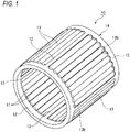
FIG. 1 is a perspective view illustrating a cage and roller according to a first embodiment of the present invention. -
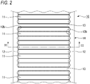
FIG. 2 is a developed view of the cage and roller ofFIG. 1 as viewed from an outer circumferential surface side. -
FIG. 3 is a cross-sectional view taken along line III-III ofFIG. 2 . -
FIG. 4 is an enlarged cross-sectional view illustrating a part of a cage and roller according to a second embodiment of the present invention. -
FIG. 5 is an enlarged cross-sectional view illustrating a part of a cage and roller according to a third embodiment of the present invention. -
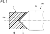
FIG. 6 is an enlarged cross-sectional view illustrating a part of a cage and roller according to a fourth embodiment of the present invention. -
FIG. 7 is an enlarged cross-sectional view illustrating a part of a cage and roller according to a fifth embodiment of the present invention. -
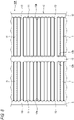
FIG. 8 is a developed view of a cage and roller according to a sixth embodiment of the present invention as viewed from an outer circumferential surface side. -
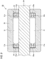
FIG. 9 is a cross-sectional view illustrating a cage and roller according to a seventh embodiment of the present invention. - Hereinafter, a cage and roller according to the present invention will be described in detail with reference to the drawings. The present invention is not limited to the embodiments to be described below, and can be appropriately modified without departing from the gist of the present invention.
- First, a cage and
roller 10 according to a first embodiment of the present invention will be described with reference toFIGS. 1 to 3 . In the following description, unless otherwise specified, an axial direction, a radial direction, a circumferential direction, an outer diameter side, and an inner diameter side indicate an axial direction, a radial direction, a circumferential direction, an outer diameter side, and an inner diameter side of the cylindrical cage and roller. - As illustrated in
FIGS. 1 and2 , the cage androller 10 of the present embodiment includes a plurality ofrollers 11 arranged in a cylindrical shape, a pair ofannular plates 12 disposed on both axial sides of the plurality ofrollers 11 and rotatably holding the plurality ofrollers 11, and a plurality of (four in the present embodiment)column portions 13 connecting the pair ofannular plates 12 in the axial direction. - As illustrated in
FIG. 3 ,protrusion portions 11a having a convex spherical shape protruding axially outward are respectively formed on both axial end surfaces of theroller 11. Theprotrusion portions 11a are formed by cutting both end portions of thecolumnar roller 11 or performing plastic working on theroller 11. - The pair of
annular plates 12 are disposed so as to sandwich both axial end portions of the plurality ofrollers 11, and the pair ofannular plates 12 are coupled in the axial direction by the fourcolumn portions 13. That is, in the present embodiment, theannular plates 12 and thecolumn portions 13 are integrally formed of synthetic resin to constitute aretainer 14. A radial thickness of thecolumn portion 13 is the same as a radial thickness of theannular plate 12. An outer diameter surface of thecolumn portion 13 is connected to be flush with an outer circumferential surface of theannular plate 12, and an inner diameter surface of thecolumn portion 13 is connected to be flush with an inner circumferential surface of theannular plate 12. In the present embodiment, ninerollers 11 are arranged between thecolumn portions 13 adjacent to each other in the circumferential direction. Further, thecolumn portions 13 are configured such that thecolumn portion 13 is not in contact with theroller 11. The number ofcolumn portions 13 is not limited to four, and may be two or more as long as the strength of theretainer 14 can be secured, and is 1/2 or less (preferably less than 1/3) of the number ofrollers 11. In addition, it is preferable that thecolumn portions 13 are arranged at substantially equal intervals in the circumferential direction, but thecolumn portions 13 may not be arranged at substantially equal intervals. - A plurality of
hole portions 12a with which theprotrusion portions 11a of each of therollers 11 are engaged are formed at substantially equal intervals in the circumferential direction in regions of axial inner end surfaces of the pair ofannular plates 12 excluding thecolumn portions 13. Thehole portion 12a is formed in a concave spherical shape. Further, a circumferential interval between thehole portions 12a adjacent to each other in the circumferential direction is set to be slightly larger than a diameter D of theroller 11. Specifically, a slight gap exists in the circumferential direction between theprotrusion portion 11a and thehole portion 12a, and the gap allows theroller 11 to be slightly displaced in the circumferential direction with respect to thehole portion 12a. The circumferential intervals of thehole portions 12a are set such that therollers 11 displaced in the circumferential direction do not come into contact with each other. Therefore, the plurality ofrollers 11 can be rotatably held in a non-contact state with each other by the plurality ofhole portions 12a of the pair ofannular plates 12. A radius of curvature R1 of the convex spherical surface of theprotrusion portion 11a is set to be smaller than a radius of curvature R2 of the concave spherical surface of thehole portion 12a (R1<R2). A center of the convex spherical surface of theprotrusion portion 11a is located on a rotation center axis (rotation axis) of theroller 11, and a center of the concave spherical surface of thehole portion 12a is located on a pitch circle diameter (PCD) of the plurality ofrollers 11. - In addition, an
insertion groove 12b for facilitating insertion of theroller 11 into thehole portion 12a is formed along the radial direction in an outer diameter-side end portion of eachhole portion 12a. Theinsertion groove 12b is formed in a semi-cylindrical shape which is an arc shape when viewed from an outer diameter side, and is formed to have a depth shallower than that of thehole portion 12a. An axial distance L2 between theinsertion grooves 12b is set to be smaller than an axial length L1 of the roller 11 (L2<L1). Further, the axial length L1 of theroller 11 is set to be smaller than an axial length L3 of the retainer 14 (L1<L3), and eachhole portion 12a does not penetrate theannular plate 12 in the axial direction, so that theroller 11 is held inside theretainer 14. Therefore, theprotrusion portion 11a which is the axial end portion of theroller 11 does not protrude from an axial outer end surface of the annular plate 12 (axial end portion of the retainer 14). - As described above, according to the cage and
roller 10 of the present embodiment, since theprotrusion portions 11a formed on both end surfaces of therollers 11 and thehole portions 12a formed in the pair ofannular plates 12 are engaged with each other, and the plurality ofrollers 11 are rotatably held in a non-contact state with each other by the pair ofannular plates 12, an increase in bearing torque of the cage androller 10 can be restricted, and seizure of therollers 11 and a decrease in allowable rotation speed can be prevented. In addition, since it is not necessary to provide the column portion between alladjacent rollers 11, the number ofrollers 11 can be set to be close to the total number of rollers in a roller bearing, and a load capacity of the cage androller 10 can be increased. - In addition, according to the cage and
roller 10 of the present embodiment, since the plurality ofrollers 11 are held by theretainer 14 by engaging theprotrusion portions 11a of therollers 11 with thehole portions 12a of the pair ofannular plates 12, therollers 11 can be prevented from falling off from theretainer 14 without providing a roller falling prevention column or a roller falling prevention tool. - Further, according to the cage and
roller 10 of the present embodiment, since the radius of curvature of the convex spherical surface of theprotrusion portion 11a of theroller 11 is set to be smaller than the radius of curvature of the concave spherical surface of thehole portion 12a of theannular plate 12, theprotrusion portion 11a and thehole portion 12a are in point contact with each other at one point. Therefore, frictional resistance between therollers 11 and theannular plates 12 can be minimized, and the increase in bearing torque of the cage androller 10 can be further prevented. - Further, according to the cage and
roller 10 of the present embodiment, since theretainer 14 is formed of synthetic resin, theretainer 14 is elastically deformed when therollers 11 are assembled into theretainer 14. Therefore, therollers 11 can be easily assembled into theretainer 14, and therollers 11 can be prevented from falling off after the assembling. In addition, since eachhole portion 12a does not penetrate theannular plate 12 in the axial direction, a decrease in strength of theannular plate 12 can be prevented. Further, since theprotrusion portion 11a does not protrude from the axial outer end surface of theannular plate 12 and the axial outer end surface of theannular plate 12 is formed in a planar shape, therollers 11 and a part of theannular plate 12 are prevented from interfering with a member adjacent to theretainer 14 in the axial direction when the cage androller 10 is used. - Further, according to the cage and
roller 10 of the present embodiment, since theinsertion groove 12b is formed in the outer diameter-side end portion of eachhole portion 12a of theannular plate 12, an amount of elastic deformation of theannular plate 12 when theroller 11 is inserted is small, and theroller 11 is easily inserted into thehole portion 12a. - Next, a cage and
roller 10B according to a second embodiment of the present invention will be described with reference toFIG. 4 . In the second and subsequent third to sixth embodiments, the configuration of theretainer 14 and the relationship between theretainer 14 and the plurality ofrollers 11 are the same as those in the first embodiment, so that the same components as those in the first embodiment are designated by the same reference numerals or equivalent reference numerals, and the description thereof will be omitted. - In the cage and
roller 10B of the present embodiment, as illustrated inFIG. 4 ,protrusion portions 11c having an elliptical spherical shape and protruding axially outward are formed on both axial end surfaces of theroller 11, andhole portions 12c having an elliptical spherical shape and engaging with theprotrusion portions 11c of theroller 11 are formed on axial inner end surfaces of the pair ofannular plates 12. Major axes of both elliptical shapes of thehole portion 12c and theprotrusion portion 11c are in the same direction as the axial direction of theroller 11, and the elliptical shape (minor axis) of thehole portion 12c is set to be smaller than the elliptical shape (minor axis) of theprotrusion portion 11c. In the present embodiment, theinsertion grooves 12b may also be formed in theannular plate 12 as in the first embodiment. - According to the cage and
roller 10B of the present embodiment, since an engagement width in the axial direction between theprotrusion portion 11c of theroller 11 and thehole portion 12c of theannular plate 12 is larger than that in the first embodiment, therollers 11 can be further prevented from falling off from theretainer 14. - Other configurations, operations, and effects are the same as those of the first embodiment.
- Next, a cage and
roller 10C according to the third embodiment of the present invention will be described with reference toFIG. 5 . - In the cage and
roller 10C of the present embodiment, as illustrated inFIG. 5 , substantially truncatedconical protrusion portions 11d protruding axially outward are formed on both axial end surfaces of theroller 11, and substantially truncatedconical hole portions 12d with which theprotrusion portions 11d of theroller 11 are engaged are formed on axial inner end surfaces of the pair ofannular plates 12. Further, in order to facilitate assembling of theroller 11 into theretainer 14, it is preferable to provide a predetermined gap (play) between a tip end of theprotrusion portion 11d and a bottom surface of thehole portion 12d. In the present embodiment, theinsertion grooves 12b may also be formed in theannular plate 12 as in the first embodiment. - According to the cage and
roller 10C of the present embodiment, since an engagement width in the axial direction between theprotrusion portion 11d of theroller 11 and thehole portion 12d of theannular plate 12 is larger than that in the first embodiment, therollers 11 can be further prevented from falling off from theretainer 14. - Other configurations, operations, and effects are the same as those of the first embodiment.
- Next, a cage and
roller 10D according to the fourth embodiment of the present invention will be described with reference toFIG. 6 . - In the cage and
roller 10D of the present embodiment, as illustrated inFIG. 6 , taperedprotrusion portions 11e protruding axially outward are formed on both axial end surfaces of theroller 11, and taperedhole portions 12e with which theprotrusion portions 11e of theroller 11 are engaged are formed on axial inner end surfaces of the pair ofannular plates 12. In the present embodiment, theinsertion grooves 12b may also be formed in theannular plate 12 as in the first embodiment. - According to the cage and
roller 10D of the present embodiment, since an engagement width in the axial direction between theprotrusion portion 11e of theroller 11 and thehole portion 12e of theannular plate 12 is larger than that in the first embodiment, therollers 11 can be further prevented from falling off from theretainer 14. - Other configurations, operations, and effects are the same as those of the first embodiment.
- Next, a cage and
roller 10E according to the fifth embodiment of the present invention will be described with reference toFIG. 7 . - In the cage and
roller 10E of the present embodiment, as illustrated inFIG. 7 ,ribs 12f protruding radially outward are formed on outer circumferential surfaces of the pair ofannular plates 12 over the entire circumference. Further, theretainer 14 is used for outer ring guide with outer peripheral surfaces of theribs 12f facing an outer ring raceway surface with a slight gap therebetween. - According to the cage and
roller 10E of the present embodiment, since theribs 12f protruding radially outward are formed on the outer circumferential surfaces of the pair ofannular plates 12, rattling of theretainer 14 in the radial direction can be prevented. Accordingly, therollers 11 can be further prevented from falling off from theretainer 14. - Other configurations, operations, and effects are the same as those of the first embodiment.
- Next, a cage and
roller 10F according to the sixth embodiment of the present invention will be described with reference toFIG. 8 . - As illustrated in
FIG. 8 , the cage androller 10F of the present embodiment includes two rows of therollers 11 of the cage androller 10 of the first embodiment. The number of rows of therollers 11 is not limited to two, and may be three or more. - Other configurations, operations, and effects are the same as those of the first embodiment.
- Next, a cage and
roller 20 according to a seventh embodiment of the present invention will be described with reference toFIG. 9 . - As illustrated in
FIG. 9 , the cage androller 20 of the present embodiment includes a plurality ofrollers 21 arranged in a cylindrical shape, and a pair ofannular plates 22 disposed on both axial sides of the plurality ofrollers 21 and rotatably holding the plurality ofrollers 21. - As illustrated in
FIG. 9 ,columnar protrusion portions 21a protruding axially outward are formed on both axial end surfaces of theroller 21. Theprotrusion portions 21a are formed at axial center positions of theroller 21. Theprotrusion portions 21a are formed integrally with theroller 21 by cutting both end portions of thecolumnar roller 21 or performing plastic working on theroller 21. - The pair of
annular plates 22 are formed separately from each other, and are disposed so as to sandwich both axial end portions of the plurality ofrollers 21. That is, column portions which connect the pair ofannular plates 22 to each other in the axial direction are not provided for the pair ofannular plates 22. Theannular plate 22 may be made of metal or synthetic resin. - In the pair of
annular plates 22, a plurality ofhole portions 22a engaged with theprotrusion portions 21a of eachroller 21 are formed at substantially equal intervals in the circumferential direction. Thehole portion 22a is a through hole penetrating theannular plate 22 in the axial direction. Further, a circumferential interval between thehole portions 22a adjacent to each other in the circumferential direction is set to be slightly larger than a diameter of theroller 21. Therefore, the plurality ofrollers 21 can be rotatably held in a non-contact state with each other by the plurality ofhole portions 22a of the pair ofannular plates 22. - In addition, since the cage and
roller 20 of the present embodiment does not include the column portions which connect the pair ofannular plates 22, the cage androller 20 is assembled into a drawncup 25 after the plurality ofrollers 21 and the pair ofannular plates 22 are combined. At the time of use, ashaft 26 is inserted into the cage androller 20. Since an axial dimension of theprotrusion portion 21a is set to be smaller than an axial dimension of thehole portion 22a (the same as the axial dimension of the annular plate 22), theprotrusion portion 21a is prevented from protruding from an axial outer end surface of theannular plate 22 and from coming into contact with the drawncup 25. - As described above, according to the cage and
roller 20 of the present embodiment, theprotrusion portions 21a formed on both end surfaces of theroller 21 and thehole portions 22a formed in the pair ofannular plates 22 are engaged with each other, and the plurality ofrollers 21 are rotatably held in a non-contact state with each other by the pair ofannular plates 22, so that an increase in bearing torque of the cage androller 20 can be restricted, and seizure of therollers 21 and a decrease in allowable rotation speed can be prevented. In addition, since it is not necessary to provide column portions which connect the pair ofannular plates 22, the number ofrollers 21 can be set to be close to a total number of rollers in a roller bearing, and a load capacity of the cage androller 20 can be increased. - As described above, the present description discloses the following matters.
- (1) A cage and roller includes:
- a plurality of rollers arranged in a cylindrical shape; and
- a pair of annular plates disposed on both axial sides of the plurality of rollers to hold the plurality of rollers, in which:
- the plurality of rollers have protrusion portions on both axial end surfaces thereof; and
- the pair of annular plates have a plurality of hole portions with which the protrusion portions of the plurality of rollers are engaged, and rotatably hold the plurality of rollers in a non-contact state with each other.
- (2) The cage and roller according to (1) further includes two or more column portions connecting the pair of annular plates, and at least two of the rollers are arranged between the column portions adjacent to each other in a circumferential direction.
- (3) In the cage and roller according to (2), the annular plates and the column portions are made of resin, and
an insertion groove for facilitating insertion of the rollers into the hole portions is formed along a radial direction in an outer diameter-side end portion of the hole portions. - (4) In the cage and roller according to (1), the pair of annular plates are separated from each other.
- (5) In the cage and roller according to (4), the protrusion portions have columnar shape and are formed at an axial center position of the rollers, and
the hole portions are through hole penetrating the annular plate in an axial direction. - (6) The cage and roller according to (4) or (5) is assembled in a drawn cup.
- According to the configuration, the protrusion portions formed on the both end surfaces of the roller are engaged with the hole portions formed in the pair of annular plates, and the plurality of rollers are rotatably held in a non-contact state with each other by the pair of annular plates, so that a load capacity can be increased while restricting an increase in bearing torque.
- Although various embodiments have been described above with reference to the drawings, it is needless to say that the present invention is not limited to such examples. It is apparent to those skilled in the art that various changes and modifications can be conceived within the scope of the claims, and it is also understood that such variations and modifications belong to the technical scope of the present invention. In addition, constituent elements in the embodiments described above may be combined freely within a range not departing from the spirit of the present invention.
- The present application is based on Japanese patent application (
Japanese Patent Application NO. 2020-38707) filed on Mar. 6, 2020 -
- 10, 10B, 10C, 10D, 10E, 10F, 20: cage and roller
- 11, 21: roller
- 11a, 11c, 11d, 11e, 21a: protrusion portion
- 12, 22: annular plate
- 12a, 12c, 12d, 12e, 22a: hole portion
- 12b: insertion groove
- 12f: rib
- 13: column portion
- 14: retainer
- 25: drawn cup
- 26: shaft
Claims (6)
- A cage and roller comprising:a plurality of rollers arranged in a cylindrical shape; anda pair of annular plates disposed on both axial sides of the plurality of rollers to hold the plurality of rollers, wherein:the plurality of rollers have protrusion portions on both axial end surfaces thereof; andthe pair of annular plates have a plurality of hole portions with which the protrusion portions of the plurality of rollers are engaged, and rotatably hold the plurality of rollers in a non-contact state with each other.
- The cage and roller according to claim 1 further comprising:two or more column portions connecting the pair of annular plates, whereinat least two of the rollers are arranged between the column portions adjacent to each other in a circumferential direction.
- The cage and roller according to claim 2, wherein:the annular plates and the column portions are made of resin; andan insertion groove for facilitating insertion of the rollers into the hole portions is formed along a radial direction in an outer diameter-side end portion of the hole portions.
- The cage and roller according to claim 1, wherein
the pair of annular plates are separated from each other. - The cage and roller according to claim 4, wherein:the protrusion portions have columnar shape and are formed at an axial center position of the rollers; andthe hole portions are through hole penetrating the annular plate in an axial direction.
- The cage and roller according to claim 4 or 5, wherein
the cage and roller is assembled in a drawn cup.
Applications Claiming Priority (2)
| Application Number | Priority Date | Filing Date | Title |
|---|---|---|---|
| JP2020038707A JP2021139455A (en) | 2020-03-06 | 2020-03-06 | Cage-and-roller |
| PCT/JP2021/008244 WO2021177366A1 (en) | 2020-03-06 | 2021-03-03 | Cage and roller |
Publications (2)
| Publication Number | Publication Date |
|---|---|
| EP4116595A1 true EP4116595A1 (en) | 2023-01-11 |
| EP4116595A4 EP4116595A4 (en) | 2023-07-26 |
Family
ID=77613413
Family Applications (1)
| Application Number | Title | Priority Date | Filing Date |
|---|---|---|---|
| EP21764324.6A Withdrawn EP4116595A4 (en) | 2020-03-06 | 2021-03-03 | Cage and roller |
Country Status (4)
| Country | Link |
|---|---|
| EP (1) | EP4116595A4 (en) |
| JP (1) | JP2021139455A (en) |
| CN (1) | CN115244306A (en) |
| WO (1) | WO2021177366A1 (en) |
Families Citing this family (2)
| Publication number | Priority date | Publication date | Assignee | Title |
|---|---|---|---|---|
| JP7776814B2 (en) * | 2020-08-27 | 2025-11-27 | 株式会社ゼロボード | Information processing device |
| CN118490153B (en) * | 2024-06-24 | 2025-12-05 | 哈尔滨思哲睿智能医疗设备股份有限公司 | Laparoscopic rotating device |
Family Cites Families (13)
| Publication number | Priority date | Publication date | Assignee | Title |
|---|---|---|---|---|
| FR1135019A (en) * | 1955-10-28 | 1957-04-23 | Roulements A Aiguilles Sa | Rolling |
| JPH0828575A (en) * | 1994-07-15 | 1996-02-02 | Hitachi Constr Mach Co Ltd | Planetary gear reducer |
| JP4618915B2 (en) | 2001-03-14 | 2011-01-26 | Ntn株式会社 | Full roller bearing and planetary gear reduction device using the same |
| JP2007187287A (en) | 2006-01-16 | 2007-07-26 | Ntn Corp | Roller bearing for rack/pinion mechanism |
| JP2013053713A (en) * | 2011-09-06 | 2013-03-21 | Jtekt Corp | Roller bearing and wind power generator speed increasing gear |
| ITUD20110177A1 (en) * | 2011-11-08 | 2013-05-09 | Danieli Off Mecc | SUPPORT BEARING FOR A ROLLER |
| JP2013185640A (en) | 2012-03-07 | 2013-09-19 | Ntn Corp | Cylindrical roller bearing |
| DE102013215848A1 (en) * | 2013-08-12 | 2015-02-12 | Schaeffler Technologies Gmbh & Co. Kg | roller bearing |
| KR20170021340A (en) * | 2014-07-30 | 2017-02-27 | 코요 베어링즈 노쓰 아메리카 엘엘씨 | Roller bearing assembly with retainer ring |
| JP6613576B2 (en) | 2015-02-25 | 2019-12-04 | 日本精工株式会社 | Bearing cage and cage and roller |
| JP2019039557A (en) * | 2017-08-25 | 2019-03-14 | 加茂精工株式会社 | bearing |
| CN110030274A (en) * | 2019-01-23 | 2019-07-19 | 舍弗勒技术股份两合公司 | Cage for a rolling bearing, rolling element and rolling bearing |
| JP2020038707A (en) | 2019-11-14 | 2020-03-12 | パイオニア株式会社 | Charge amount calculation device |
-
2020
- 2020-03-06 JP JP2020038707A patent/JP2021139455A/en active Pending
-
2021
- 2021-03-03 EP EP21764324.6A patent/EP4116595A4/en not_active Withdrawn
- 2021-03-03 CN CN202180019130.8A patent/CN115244306A/en not_active Withdrawn
- 2021-03-03 WO PCT/JP2021/008244 patent/WO2021177366A1/en not_active Ceased
Also Published As
| Publication number | Publication date |
|---|---|
| CN115244306A (en) | 2022-10-25 |
| JP2021139455A (en) | 2021-09-16 |
| EP4116595A4 (en) | 2023-07-26 |
| WO2021177366A1 (en) | 2021-09-10 |
Similar Documents
| Publication | Publication Date | Title |
|---|---|---|
| CN102803767B (en) | Synthetic resin cage for deep groove ball bearing, deep groove ball bearing and gear support device | |
| CN104763750B (en) | Single joint cage | |
| EP2913547A1 (en) | Cylindrical roller bearing | |
| US20040141672A1 (en) | Resin-made ball retainer for a rolling bearing | |
| JPH05157116A (en) | Spherical roller bearing with cage | |
| EP1947356A2 (en) | Cage for rolling bearing and rolling bearing having the same | |
| JP6234137B2 (en) | Deep groove ball bearing | |
| JP7485948B2 (en) | Cage for spherical roller bearing | |
| WO2012033043A1 (en) | Reduction device | |
| JP5655473B2 (en) | Thrust ball bearing | |
| US11248656B2 (en) | Cage and roller assembly | |
| KR20030007115A (en) | One-way clutch unit | |
| US7891881B2 (en) | Drawn cup roller bearing | |
| US10655678B2 (en) | Cage and roller assembly | |
| WO2021177366A1 (en) | Cage and roller | |
| CN113631820B (en) | Angular contact ball bearings with separable inner ring | |
| JP2000320558A (en) | Synthetic resin cage for roller bearings | |
| US10634191B2 (en) | Cage and roller assembly | |
| EP4112956B1 (en) | Cylindrical roller bearing with outer ring | |
| JP2009275799A (en) | Deep groove ball bearing | |
| JP2011021661A (en) | Synthetic resin holder for deep groove ball bearing, and deep groove ball bearing | |
| EP3926192A1 (en) | Multi-row thrust ball bearing | |
| JP2016151345A (en) | Deep groove ball bearing | |
| JP7544315B2 (en) | Cage for spherical roller bearing | |
| JP2019094995A (en) | Holder for radial roller bearing |
Legal Events
| Date | Code | Title | Description |
|---|---|---|---|
| STAA | Information on the status of an ep patent application or granted ep patent |
Free format text: STATUS: THE INTERNATIONAL PUBLICATION HAS BEEN MADE |
|
| PUAI | Public reference made under article 153(3) epc to a published international application that has entered the european phase |
Free format text: ORIGINAL CODE: 0009012 |
|
| STAA | Information on the status of an ep patent application or granted ep patent |
Free format text: STATUS: REQUEST FOR EXAMINATION WAS MADE |
|
| 17P | Request for examination filed |
Effective date: 20220906 |
|
| AK | Designated contracting states |
Kind code of ref document: A1 Designated state(s): AL AT BE BG CH CY CZ DE DK EE ES FI FR GB GR HR HU IE IS IT LI LT LU LV MC MK MT NL NO PL PT RO RS SE SI SK SM TR |
|
| DAV | Request for validation of the european patent (deleted) | ||
| DAX | Request for extension of the european patent (deleted) | ||
| A4 | Supplementary search report drawn up and despatched |
Effective date: 20230626 |
|
| RIC1 | Information provided on ipc code assigned before grant |
Ipc: F16C 33/58 20060101ALI20230620BHEP Ipc: F16C 33/56 20060101ALI20230620BHEP Ipc: F16C 33/48 20060101ALI20230620BHEP Ipc: F16C 33/46 20060101ALI20230620BHEP Ipc: F16C 33/34 20060101ALI20230620BHEP Ipc: F16C 19/48 20060101ALI20230620BHEP Ipc: F16C 19/46 20060101AFI20230620BHEP Ipc: F16C 19/24 20060101ALI20230620BHEP |
|
| STAA | Information on the status of an ep patent application or granted ep patent |
Free format text: STATUS: THE APPLICATION IS DEEMED TO BE WITHDRAWN |
|
| 18D | Application deemed to be withdrawn |
Effective date: 20240124 |