EP4116538A1 - A rope ladder with two braided ropes - Google Patents
A rope ladder with two braided ropes Download PDFInfo
- Publication number
- EP4116538A1 EP4116538A1 EP21400015.0A EP21400015A EP4116538A1 EP 4116538 A1 EP4116538 A1 EP 4116538A1 EP 21400015 A EP21400015 A EP 21400015A EP 4116538 A1 EP4116538 A1 EP 4116538A1
- Authority
- EP
- European Patent Office
- Prior art keywords
- ladder
- rope
- braided
- plate
- strands
- Prior art date
- Legal status (The legal status is an assumption and is not a legal conclusion. Google has not performed a legal analysis and makes no representation as to the accuracy of the status listed.)
- Granted
Links
Images



Classifications
-
- E—FIXED CONSTRUCTIONS
- E06—DOORS, WINDOWS, SHUTTERS, OR ROLLER BLINDS IN GENERAL; LADDERS
- E06C—LADDERS
- E06C1/00—Ladders in general
- E06C1/52—Ladders in general with non-rigid longitudinal members
- E06C1/56—Rope or chain ladders
Definitions
- the present invention is related to a rope ladder with a first braided rope, a second braided rope, and a plurality of ladder steps.
- Rope ladders are widely used in civil, parapublic and military missions.
- rope ladders may be used with a rotary wing aircraft, in particular a helicopter, for on- and off-boarding, searching and rescuing, evacuating and extracting persons from various environments, including maritime environments such as offshore as well as oil and gas platforms, terrestrial environments such as land in vegetated areas, mountains and urban territory, or from aerial work to an inside of the helicopter with own muscular force without a need for a winch or a landing operation of the helicopter.
- rope ladders are known from the state-of-the-art. These rope ladders vary with respect to the manner in which respective ladder steps are secured to associated ropes, but also with respect to respectively used ropes. For instance, illustrative rope ladders with simple ropes are described in the documents GB 1 285 334 A and GB 2 367 585 A . Illustrative rope ladders with twisted ropes are described in the documents GB 2 552 204 A , US 3,128,843 , US 3,415,341 , and US 6,902,037 B2 .
- each braided rope is formed of a plurality of braided strands.
- the braided strands of each braided rope are respectively separated into two groups and an aperture is formed into which is mounted a reinforcing member or bushing.
- the reinforcing members or bushings in both braided ropes are then respectively used as bearings for the ladder step that is secured by means of a self-locking nut at two plug halves which are mounted to each braided rope around each reinforcing member or bushing to keep the latter in place.
- an object of the present invention to provide a new rope ladder with braided ropes which allows for a quick and reliable visual inspection as well as an easy and uncomplicated exchange of its constituting components.
- a rope ladder with braided ropes that comprises the features of claim 1. More specifically, according to the present invention a rope ladder with a first braided rope, a second braided rope, and a plurality of ladder steps is provided.
- the rope ladder comprises at least one first ladder step connecting element that is mounted to the first braided rope, at least one second ladder step connecting element that is mounted to the second braided rope, and at least one associated ladder step of the plurality of ladder steps that couples the at least one first ladder step connecting element with the at least one second ladder step connecting element.
- the at least one first ladder step connecting element is braided into the first braided rope and the at least one second ladder step connecting element is braided into the second braided rope.
- the at least one associated ladder step of the plurality of ladder steps fixes the at least one first ladder step connecting element in the first braided rope and the at least one second ladder step connecting element in the second braided rope.
- the inventive rope ladder may easily be inspected, in particular visually inspected, and repaired in case of deterioration. Furthermore, an underlying length of the rope ladder is adjustable and ladder steps may be added as required. Accordingly, the inventive rope ladder is modular and assembled from two braided ropes, a plurality of ladder step connecting elements, as well as a plurality of ladder steps. At least the ladder steps of the plurality of ladder steps and the ladder step connecting elements of the plurality of ladder step connecting elements are preferably exchangeable.
- the two braided ropes may preferably be opened, respectively pulled open, at arbitrarily selected positions along the braided ropes, without a need to fully open the braided ropes over their whole lengths.
- respective ladder step connecting elements may be interweaved at these arbitrarily selected positions and, subsequently, a ladder step may be inserted in each ladder step connecting element such that the ladder step connecting element is locked in the braided rope and may not be removed from the braided rope without removing the ladder step therefrom.
- each ladder step connecting element is embodied as a braiding member and, more particularly, as a braiding plate.
- the braiding plate may be made of a metallic material and may have a substantially annular design with smooth rounded edges.
- each braided rope comprises eight strands and, more particularly, four pairs of strands which are braided to form the braided rope.
- Use of eight strands, i. e. four pairs of strands, enables a redundant rope design and provision of damage tolerant braided ropes.
- each braiding plate may have six recesses, e. g. one upper, one lower, two left hand and two right hand recesses, into which the eight strands of an associated braided rope are inserted.
- a circular opening is foreseen which has a diameter that corresponds at least to the diameter of a respective ladder step.
- each braiding plate preferably comprises through-holes on at least two diametrically opposed lateral legs.
- a thread may be provided in the through-hole of one of the at least two diametrically opposed lateral legs and the through-hole in the other one of the at least two diametrically opposed lateral legs may have two different diameters in order to form a bearing surface on which a head of a locking screw can rest.
- the two braided ropes may be manufactured, i. e. braided, automatically.
- the braiding plates and respective ladder steps may be manufactured independent of each other and of the two braided ropes and attached to the two braided ropes afterwards to assemble the inventive rope ladder.
- each braided rope may be arranged in parallel, each braided rope being braided over its entire length and consisting of eight strands, i. e. four pairs of strands.
- the braiding of each braided rope is preferably designed such that the strands are movable relative to one another in a not-tensioned and released condition of each braided rope, which may thus be widened respectively nondestructively opened at selected positions.
- a respective widening of a given braided rope enables insertion of a braiding plate laterally into the given braided rope at a selected position.
- preferably four strands of the braided rope are inserted through the braiding plate from its front side and the other four strands through the braiding plate from its back side. All strands are guided from the front or rear side through associated recesses such that ultimately the braiding plate is completely interweaved into all eight strands and the braiding plate is, thus, braided into the braided rope.
- this is done such that an unoccupied opening is maintained in the center of the braiding plate that has at least the diameter of a ladder step, which may thus be passed through this unoccupied opening.
- corresponding ends of the ladder step are inserted through respective openings in two braiding plates of both parallel braided ropes that are to be interconnected by the ladder step. This is performed such that the through-holes in the braiding plates and respective bores in the ladder step are aligned with one another so that the ladder step may be secured, e. g. with screws, to the braiding plates.
- a removal of a selected ladder step and associated braiding plates may be carried out in reverse order.
- an underlying distance between an outer surface of a ladder step that is mounted to a braiding plate and an outer contour of the at least two diametrically opposed lateral legs of the braiding plate is designed to have a width that corresponds at least to the thickness of a human finger, preferentially at least three centimeters, in order to provide a floor spacing portion between the ladder step and e. g. a helicopter floor to which the inventive rope ladder is attached.
- This feature guarantees enough clearance in order to allow a comfortable and safe grabbing of ladder steps when an upper area of the inventive rope ladder lies on the helicopter floor.
- the at least one first ladder step connecting element is embodied as a first braiding member
- the at least one second ladder step connecting element is embodied as a second braiding member
- each one of the first braiding member and the second braiding member comprises a ring-shaped body with an inner opening.
- the inner opening exhibits at least a six-petalled Rosette shape.
- the inner opening is composed of a central opening with a predetermined number of radial extensions.
- the radial extensions of the predetermined number of radial extensions are separated from each other by associated retaining fingers which extend from the ring-shaped body radially inward toward the central opening.
- the associated retaining fingers comprise free ends which form bearing support surfaces that define a diameter of the central opening.
- the diameter of the central opening corresponds to a diameter of the at least one associated ladder step of the plurality of ladder steps.
- the first braided rope and the second braided rope are braided into the radial extensions of the predetermined number of radial extensions.
- the at least one associated ladder step of the plurality of ladder steps is mounted to the central opening such that the at least one associated ladder step blocks the first braided rope and the second braided rope in the radial extensions of the predetermined number of radial extensions.
- the ring-shaped body has a thickness of at least three centimeters.
- the first braided rope comprises a first predetermined number of strands which are braided together to form the first braided rope, wherein the at least one first ladder step connecting element is braided into the first predetermined number of strands.
- the second braided rope comprises a second predetermined number of strands which are braided together to form the second braided rope, wherein the at least one second ladder step connecting element is braided into the second predetermined number of strands.
- each one of the first braiding member and the second braiding member comprises a first plate-shaped surface and a second plate-shaped surface.
- a first number of strands of the first predetermined number of strands is guided on the first braiding member from the first plate-shaped surface toward the second plate-shaped surface and back to the first plate-shaped surface, and a second number of strands of the first predetermined number of strands is guided on the first braiding member from the second plate-shaped surface toward the first plate-shaped surface and back to the second plate-shaped surface.
- a first number of strands of the second predetermined number of strands is guided on the second braiding member from the first plate-shaped surface toward the second plate-shaped surface and back to the first plate-shaped surface, and a second number of strands of the second predetermined number of strands is guided on the second braiding member from the second plate-shaped surface toward the first plate-shaped surface and back to the second plate-shaped surface.
- each one of the first braided rope and the second braided rope comprises a first, a second, a third, and a fourth pair of strands that are braided together.
- the at least one first ladder step connecting element is braided into the first, second, third, and fourth pair of strands of the first braided rope.
- the at least one second ladder step connecting element is braided into the first, second, third, and fourth pair of strands of the second braided rope.
- each one of the first braiding member and the second braiding member comprises a first plate-shaped surface and a second plate-shaped surface.
- the first and second pairs of strands of the first predetermined number of strands are guided on the first braiding member from the first plate-shaped surface toward the second plate-shaped surface and back to the first plate-shaped surface, and the third and fourth pairs of strands of the first predetermined number of strands are guided on the first braiding member from the second plate-shaped surface toward the first plate-shaped surface and back to the second plate-shaped surface.
- the third and fourth pairs of strands of the second predetermined number of strands are guided on the second braiding member from the first plate-shaped surface toward the second plate-shaped surface and back to the first plate-shaped surface, and the third and fourth pairs of strands of the second predetermined number of strands are guided on the second braiding member from the second plate-shaped surface toward the first plate-shaped surface and back to the second plate-shaped surface.
- the first and second braided ropes are at least partly provided with associated spacing and protecting elements.
- the associated spacing and protecting elements preferably surround the first and second braided ropes.
- the associated spacing and protecting elements are designed as exchangeable parts to allow full exchange and inspection of all parts of the inventive rope ladder. Furthermore, the associated spacing and protecting elements ensure an improved grabbing, e. g. if the inventive rope ladder is attached to and at least partly lying on a helicopter floor. Moreover, the associated spacing and protecting elements protect the inventive rope ladder and surrounding elements, such as e. g. the helicopter floor, and even provide for floatation capabilities of the inventive rope ladder.
- the associated spacing and protecting elements are preferably made of foam that is surrounded by a textile, both of which are wrapped around the braided ropes and secured thereon, e. g. by means of Velcro fasteners.
- the main function of the associated spacing and protecting elements is to protect the braided rope from abrasion, as well as to provide a distancing between the ladder steps and e. g. the helicopter floor in order to enable a more comfortable and safer grabbing of the ladder steps.
- Respective properties of the associated spacing and protecting elements such as foam density, hardness, geometry, and surface texture, may be adapted in an application-specific manner, e. g. to enable use of the inventive rope ladder either as buoyancy or weight in fluids, abrasive protection, e. g. especially on a support edge on the helicopter floor, or adapting it to human needs, such as e. g. finger pinching protection or anti slipping means, so that the inventive rope ladder lies safely on the helicopter floor and a sideward slipping is avoided.
- the inventive ladder is equipped with rope interfaces that enable attachment of the rope ladder to one or more external attachment points.
- the rope interfaces may be embodied by eyelets, in particular metal eyelets, which are embedded in spliced respectively inter braided axial ends of the two braided ropes. This allows the usage of common fixation elements like hooks or ropes.
- the rope interfaces may e. g. be attached to an associated attachment unit, e. g. an attachment plate, which is attachable to external components. More specifically, such an attachment plate preferably comprises an upper center hole and two upper side holes, and may be used for a one- or multiple-point attachment, e. g. on a helicopter side. Furthermore, the attachment plate may be attached on one end or on both ends of the inventive rope ladder by means of the rope interfaces. Attachment to both ends of the inventive rope ladder may advantageously enable attachment of additional equipment on one end of the rope ladder.
- an attachment plate preferably comprises an upper center hole and two upper side holes, and may be used for a one- or multiple-point attachment, e. g. on a helicopter side.
- the attachment plate may be attached on one end or on both ends of the inventive rope ladder by means of the rope interfaces. Attachment to both ends of the inventive rope ladder may advantageously enable attachment of additional equipment on one end of the rope ladder.
- a one-point attachment may e.g. be used when the upper center hole of the attachment plate is e. g. attached to a winch of a helicopter, which is usually located over a side door of the helicopter by means of an associated snap hook respectively carabiner.
- the multi-point attachment may e. g. be used when at least the two upper side holes are attached to a floor/structure inside the helicopter by means of associated snap hooks respectively carabiners.
- the inventive rope ladder has an advantageous modular design that allows full inspection and full exchange of all constituent components, as well as a simple, economic, reliable and quick method of operation, including assembling and disassembling of the inventive rope ladder.
- the inventive rope ladder fulfills the safety requirements for human external cargo according to the US-American Federal Aviation Regulations (FAR) and/or the European Certification Specifications (CS) and is, thus, readily certifiable.
- FAR Federal Aviation Regulations
- CS European Certification Specifications
- Figure 1 shows a rotary wing aircraft 1 that illustratively comprises a fuselage 2 with a bottom shell 2e.
- the rotary wing aircraft 1 is seen in direction of a starboard side wall 2d of the fuselage 2, which is by way of example provided with a starboard side sliding door 2g.
- the fuselage 2 illustratively forms a cabin 2b for passengers and/or cargo and comprises a tail boom 2a.
- the tail boom 2a is mounted to a rear side 2c of the fuselage 2, which is also referred to as the "rear fuselage 2c" hereinafter.
- the rear fuselage 2c may be provided with a rear ramp 2f that is e. g. pivotally mounted to the fuselage 2 at the bottom shell 2e.
- the rotary wing aircraft 1 comprises a landing gear 6, which is exemplarily embodied as a wheel-type landing gear that comprises associated landing gear nose wheels 6a, a portside rear wheel 6b and a starboard side rear wheel 6c.
- the rotary wing aircraft 1 illustratively further comprises at least one main rotor 1a configured to provide lift and forward or backward thrust during operation, and at least one counter-torque device 3 configured to provide counter-torque during operation, i. e. to counter the torque created by rotation of the at least one main rotor 1a for purposes of balancing the rotary wing aircraft 1 in terms of yaw.
- the at least one counter-torque device 3 is illustratively provided at an aft section of the tail boom 2a, which preferably further comprises a tail wing 4 and a fin 5.
- the tail wing 4 is preferably adjustable in its inclination and can, thus, overtake the functioning of a horizontal stabilizer.
- the rotary wing aircraft 1 may be provided with a suitable horizontal stabilizer.
- the at least one counter-torque device 3, the tail wing 4 as well as the fin 5 provided at the aft section of the tail boom 2a are merely described for illustrating one illustrative realization of the rotary wing aircraft 1.
- the rotary wing aircraft 1 is provided with a rope ladder 8.
- the rope ladder 8 is attached to the rear ramp 2f.
- the rope ladder 8 and/or its constituent components are further described below with reference to Figure 2 to Figure 11 .
- the rotary wing aircraft 1 is shown during hovering above ground 9.
- the rope ladder 8 may e. g. be used for rescuing, evacuating and/or extracting persons located on the ground 9.
- the rotary wing aircraft 1 is embodied as a helicopter.
- use of the rope ladder 8 is not limited to use with a helicopter.
- the rope ladder 8 may be used with other rotary wing aircrafts, such as e. g. tiltrotor aircrafts, compound helicopters, multicopters and so on, as well as marine vessels etc.
- the rope ladder 8 may be used completely independent of the rotary wing aircraft 1.
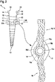
- FIG 2 shows the rope ladder 8 of Figure 1 and an enlarged detail thereof.
- the rope ladder 8 comprises a first braided rope 10, a second braided rope 11, and a plurality of ladder steps 12.
- the plurality of ladder steps 12 is individually labelled with the reference sign 12a.
- At least one of the braided ropes 10, 11 is provided on at least one of its axial ends with a rope interface 13.
- both braided ropes 10, 11 are provided on their - in Figure 2 upper - axial ends with a respective rope interface 13.
- Each rope interface 13 is preferably embodied by an eyelet 14, in particular a metal eyelet, which is embedded in a spliced respectively inter braided area 15 formed at the axial end of the braided rope 10, 11.
- each braided rope 10, 11 comprises a predetermined number of strands 16 which are braided together to form the braided ropes 10, 11.
- the predetermined number may be eight.
- each one of the braided ropes 10, 11 comprises a first, a second, a third, and a fourth pair of strands 16a, 16b, 16c, 16d that are braided together.
- each braided rope 10, 11 is provided with at least one and, preferentially, with a plurality of ladder step connecting elements. All ladder step connecting elements are preferably identical within predetermined manufacturing tolerances.
- Pairs of ladder step connecting elements that are each associated with a respective ladder step are braided into the braided rope 10 and the braided rope 11 and preferably oppose each other in the rope ladder 8 and are coupled to each other by the respective ladder step.
- one ladder step connecting element in the braided rope 10 is labelled with the reference sign 17 and an opposed ladder step connecting element in the braided rope 11 is likewise labelled with the reference sign 17.
- These two ladder step connecting elements 17 are illustratively coupled to each other via the ladder step 12a.
- the ladder step 12a preferably fixes the ladder step connecting elements 17 in the braided ropes 10, 11.
- the ladder step connecting element 17 of the braided rope 10 is braided into the predetermined number of strands 16 of the braided rope 10, i. e. by way of example into the first, second, third, and fourth pair of strands 16a, 16b, 16c, 16d of the braided rope 10.
- the ladder step connecting element 17 of the braided rope 11 is braided into the predetermined number of strands 16 of the braided rope 11, i. e. by way of example into the first, second, third, and fourth pair of strands 16a, 16b, 16c, 16d of the braided rope 11.
- each one of the ladder step connecting elements 17 is embodied as a braiding member 18.
- the braiding member 18 is formed as a braiding plate.
- ladder step connecting elements are collectively referred to with the reference sign 17, as all ladder step connecting elements are preferably identical within predetermined manufacturing tolerances. Therefore, only one of the ladder step connecting elements 17 is representatively described in more detail hereinafter with reference to Figure 3 to Figure 5 . Similarly, only braiding of this ladder step connecting element 17 into either one of the braided ropes 10, 11 is representatively described below with reference to Figure 6 and Figure 7 .
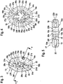
- FIG 3 shows the ladder step connecting element 17 of Figure 2 .
- the ladder step connecting element 17 is embodied as the braiding member 18 of Figure 2 , which illustratively comprises a plate-shaped front surface 18a, a plate-shaped rear surface 18b, and an inner braiding area 18c.
- the plate-shaped rear surface 18b is shown.
- the braiding member 18 comprises a ring-shaped body 19 with an inner opening 19a that forms the inner braiding area 18c.
- the inner opening 19a exhibits a six-petalled Rosette shape, i. e. is formed with a six-petalled Rosette shaped circumference 19b.
- the inner opening 19a is preferably composed of a central opening 20 with a predetermined number of radial extensions.
- a predetermined number of radial extensions By way of example, six radial extensions 20a, 20b, 20c, 20d, 20e, 20f are illustrated.
- the ring-shaped body 19 further comprises a predetermined number of external recesses.
- a predetermined number of external recesses By way of example, six external recesses 21a, 21b, 21c, 21d, 21e, 21f are provided.
- the external recesses 21a, 21b, 21c, 21d, 21e, 21f may be provided to enable a comfortable handling and grabbing of the ring-shaped body 19.
- the ring-shaped body 19 is further provided with two diametrically opposed through-holes 22.
- the through-holes 22 are preferentially adapted to receive a ladder step fixing element (28 in Figure 8 to Figure 10 ), such as a self-locking screw.
- a ladder step fixing element such as a self-locking screw.
- one of the through-holes 22 comprises a bearing surface 22a that is e. g. adapted for bearing of an associated screw head.
- Figure 4 shows the ladder step connecting element 17, i. e. the braiding member 18 of Figure 3 , to further illustrate its plate-shaped rear surface 18b.
- the braiding member 18 comprises the ring-shaped body 19 with the inner opening 19a that forms the inner braiding area 18c and that is composed of the central opening 20 and the six radial extensions 20a, 20b, 20c, 20d, 20e, 20f.
- the inner braiding area 18c is formed by means of a predetermined number of retaining fingers.
- retaining fingers 19c, 19d, 19e, 19f, 19g, 19h are provided.
- the retaining fingers 19c, 19d, 19e, 19f, 19g, 19h illustratively extend from the ring-shaped body 19 radially inward toward the central opening 20 and preferably separate the radial extensions 20a, 20b, 20c, 20d, 20e, 20f from each other.
- the retaining fingers 19c, 19d, 19e, 19f, 19g, 19h comprise free ends 23a, 23b, 23c, 23d, 23e, 23f which form bearing support surfaces for bearing of an associated ladder step, e. g. the ladder step 12a of Figure 2 .
- the bearing support surfaces 23a, 23b, 23c, 23d, 23e, 23f preferentially define a diameter (26 in Figure 7 ) of the central opening 20 that corresponds at least approximately to a diameter (12b in Figure 8 ) of the ladder step.
- Figure 5 shows the ladder step connecting element 17, i. e. the braiding member 18 of Figure 3 , to further illustrate the through-holes 22 and the bearing surface 22a. Furthermore, the central opening 20 is further illustrated by means of its maximum diameter.
- FIG 6 and Figure 7 show an illustrative method of braiding the ladder step connecting elements 17, i. e. the braiding members 18 of Figure 2 to Figure 5 into the braided ropes 10, 11 of Figure 2 in order to enable fixation of the ladder step 12a of Figure 2 at the braiding members 18.
- each one of the braided ropes 10, 11 comprises the first, second, third, and fourth pair of strands 16a, 16b, 16c, 16d according to Figure 2
- each one of the braiding members 18 comprises the ring-shaped body 19 with the plate-shaped front surface 18a, the plate-shaped rear surface 18b, and the inner braiding area 18c according to Figure 3 to Figure 5 .
- the ring-shaped body 19 has a thickness 27 that corresponds at least to the average thickness of a human finger. Preferably, the thickness amounts at least to three centimeters.
- a comfortable grabbing of the ladder step 12a is enabled after assembling of the rope ladder 8 of Figure 1 and Figure 2 .
- the braided rope 10 is opened, i. e. pulled open, in an area 24 into which the braiding member 18 is to be inserted. According to one aspect, this is performed in a nondestructive manner by simply unbraiding, i. e. disentangling, the braided rope 10 in the area 24.
- the braiding member 18 is then positioned in the area 24 such that the first and second pairs of strands 16a, 16b are located at the plate-shaped front surface 18a of the braiding member 18, while the third and fourth pairs of strands 16c, 16d are located at the plate-shaped rear surface 18b.
- a first number of strands by way of example the pairs of strands 16a, 16b
- a second number of strands is guided on the braiding member 18 from the plate-shaped rear surface 18b toward the plate-shaped front surface 18a and back to the plate-shaped rear surface 18b, as illustrated with arrows 25g, 25h.
- the pair of strands 16a is guided on the braiding member 18 from the plate-shaped front surface 18a through the radial extension 20a toward the plate-shaped rear surface 18b and through the radial extension 20c back to the plate-shaped front surface 18a.
- the pair of strands 16a is retained on the plate-shaped rear surface 18b by the retaining fingers 19c, 19d.
- the pair of strands 16b is guided on the braiding member 18 from the plate-shaped front surface 18a through the radial extension 20b toward the plate-shaped rear surface 18b and through the radial extension 20d back to the plate-shaped front surface 18a.
- the pair of strands 16b is retained on the plate-shaped rear surface 18b by the retaining fingers 19d, 19e.
- the pair of strands 16c is guided on the braiding member 18 from the plate-shaped rear surface 18b through the radial extension 20d toward the plate-shaped front surface 18a and through the radial extension 20f back to the plate-shaped rear surface 18b.
- the pair of strands 16b is retained on the plate-shaped front surface 18a by the retaining fingers 19f, 19g.
- the pair of strands 16d is guided on the braiding member 18 from the plate-shaped rear surface 18b through the radial extension 20e toward the plate-shaped front surface 18a and through the radial extension 20a back to the plate-shaped rear surface 18b.
- the pair of strands 16d is retained on the plate-shaped front surface 18a by the retaining fingers 19g, 19h.
- Guidance of the pair of strands 16a through the radial extensions 20a, 20c is further illustrated in Figure 7 , as well as guidance of the pair of strands 16b through the radial extensions 20b, 20d, the pair of strands 16c through the radial extensions 20d, 20f, and the pair of strands 16d through the radial extensions 20e, 20a.
- the braided rope 10 is braided into the radial extensions 20a, 20b, 20c, 20d, 20e, 20f of the braiding member 18.
- the braided rope 10 is braided into the radial extensions 20a, 20b, 20c, 20d, 20e, 20f of the braiding member 18 as illustrated in Figure 7 such that the pairs of strands 16a, 16b, 16c, 16d do not occupy the central opening 20 of Figure 4 , which illustratively comprises a diameter 26.
- the diameter 26 of the central opening 20 is adapted to permit insertion of the ladder step 12a of Figure 2 therethrough.
- the ladder step 12a is preferably mountable to the central opening 20 such that the ladder step 12a blocks the braided ropes 10, 11 in the radial extensions 20a, 20b, 20c, 20d, 20e, 20f.
- Figure 8 shows the braided ropes 10, 11 with the ladder step connecting elements 17, i. e. the braiding members 18, braided thereinto according to Figure 6 and Figure 7 .
- the ladder step connecting element 17 in the braided rope 10 is now coupled via the ladder step 12a to the ladder step connecting element 17 in the braided rope 11.
- the ladder step 12a has an outer diameter 12b.
- This outer diameter 12b is preferably at least approximately equal to, or smaller than, the diameter 26 of the central opening 20 of Figure 7 .
- the ladder step 12a is fixedly mounted, respectively secured, to the ladder step connecting elements 17, i. e. the braiding members 18, via associated fixing elements 28.
- the fixing elements 28 are e. g. self-locking screws which are mounted to the through-holes 22 of the braiding members 18 and which preferably traverse the ladder step 12a.
- FIG 9 shows the ladder step 12a which is according to Figure 8 fixedly mounted, respectively secured, to the ladder step connecting elements 17, i. e. the braiding members 18, via the fixing elements 28.
- the fixing elements 28 are, by way of example, embodied as self-locking screws which are mounted to the through-holes 22 of the braiding members 18 and which illustratively comprise respective screw heads 28a.
- Figure 10 shows the ladder step 12a which is according to Figure 8 and Figure 9 fixedly mounted, respectively secured, to the ladder step connecting elements 17, i. e. the braiding members 18, via the fixing elements 28.
- the fixing elements 28 are mounted to the through-holes 22 of the braiding members 18 and illustratively traverse the ladder step 12a through respective ladder step through-holes 12c.
- Figure 10 further illustrates the outer diameter 12b of the ladder step 12a according to Figure 8 , which is preferably at least approximately equal to, or smaller than, the diameter 26 of the central opening 20 of the braiding members 18 according to Figure 7 .
- the ladder step 12a may easily be mounted to the central openings 20 and by making the through-holes 22 of the braiding members 18 congruent with the ladder step through-holes 12c, insertion of the fixing elements 28 is enabled.
- Figure 11 shows the rope ladder 8 of Figure 2 with the braided ropes 10, 11, and the plurality of ladder steps 12 that includes the ladder step 12a, as well as the rope interfaces 13 with the eyelets 14.
- the ladder step 12a and, more particularly, the plurality of ladder steps 12 is mounted to the braided ropes 10, 11 and, thus, the rope ladder 8 is assembled as described above with reference to Figure 2 to Figure 10 .
- the braided ropes 10, 11 are at least partly provided with spacing and protecting elements 34.
- the spacing and protecting elements 34 preferably surround the braided ropes 10, 11, at least between adjacent ladder steps of the plurality of ladder steps 12.
- the spacing and protecting elements 34 are made of foam that is surrounded by a textile, both of which are wrapped around the braided ropes 10, 11 and secured thereon.
- the spacing and protecting elements 34 are secured on the braided ropes 10, 11 by means of any suitable fixations 35, such as e. g. Velcro fasteners.
- the main function of the spacing and protecting elements 34 is to protect the braided ropes 10, 11 from abrasion, as well as to provide a distancing between the plurality of ladder steps 12 and e. g. an external support to which the rope ladder 8 is attached, for instance the rear ramp 2f of the rotary wing aircraft 1 of Figure 1 , in order to enable a more comfortable and safer grabbing of the ladder steps.
- Respective properties of the spacing and protecting elements 34 such as foam density, hardness, geometry, and surface texture, may be adapted in an application-specific manner, e. g. to enable use of the rope ladder 8 either as buoyancy or weight in fluids, abrasive protection, e. g.
- Attachment of the rope ladder 8 to an external support is preferably achieved by means of an attachment interface 29 to which the rope interfaces 13 are attached.
- the attachment interface 29 comprises a predetermined number of interconnected arms which illustratively form an attachment plate 29a.
- the attachment plate 29a comprises an upper inner attachment point 31, which is illustratively formed as an upper center hole, and two upper outer attachment points 32, which are illustratively formed as upper side holes.
- the attachment plate 29a preferably further comprises two lower outer attachment points 33, which are illustratively formed as lower side holes.
- the lower side holes 33 may be attached to the rope interfaces 13 by any suitable attachment means, such as e. g. snap hooks respectively carabiners 30.
- the upper center hole 31 and the upper side holes 32 may be used for a one-point attachment or a multiple-point attachment.
- a one-point attachment may for instance be used when the upper center hole 31 of the attachment plate 29a is e. g. attached by means of an associated snap hook respectively carabiner to a winch of the rotary wing aircraft 1 of Figure 1 , which may be located over the sliding door 2g of Figure 1 .
- a multi-point attachment may for instance be used when at least the two upper side holes 32 are e. g. attached by means of associated snap hooks respectively carabiners to the rear ramp 2f of the rotary wing aircraft 1, as illustrated in Figure 1 .
Landscapes
- Ladders (AREA)
Abstract
Description
- The present invention is related to a rope ladder with a first braided rope, a second braided rope, and a plurality of ladder steps.
- Rope ladders are widely used in civil, parapublic and military missions. For instance, rope ladders may be used with a rotary wing aircraft, in particular a helicopter, for on- and off-boarding, searching and rescuing, evacuating and extracting persons from various environments, including maritime environments such as offshore as well as oil and gas platforms, terrestrial environments such as land in vegetated areas, mountains and urban territory, or from aerial work to an inside of the helicopter with own muscular force without a need for a winch or a landing operation of the helicopter.
- Various rope ladders are known from the state-of-the-art. These rope ladders vary with respect to the manner in which respective ladder steps are secured to associated ropes, but also with respect to respectively used ropes. For instance, illustrative rope ladders with simple ropes are described in the documents
GB 1 285 334 A GB 2 367 585 A GB 2 552 204 A US 3,128,843 ,US 3,415,341 , andUS 6,902,037 B2 . - The document
US 3,077,241 A in turn describes a rope ladder with braided ropes, wherein each braided rope is formed of a plurality of braided strands. At each location, where a ladder step is attached to the braided ropes, the braided strands of each braided rope are respectively separated into two groups and an aperture is formed into which is mounted a reinforcing member or bushing. The reinforcing members or bushings in both braided ropes are then respectively used as bearings for the ladder step that is secured by means of a self-locking nut at two plug halves which are mounted to each braided rope around each reinforcing member or bushing to keep the latter in place. - However, any visual inspection of the condition of the braided ropes at the locations of the reinforcing members or bushings in the braided ropes requires a disassembling of the respective plug halves and, thus, removal of the associated ladder steps. Thus, inspection and maintenance of the rope ladder is complex and time-consuming.
- It is, therefore, an object of the present invention to provide a new rope ladder with braided ropes which allows for a quick and reliable visual inspection as well as an easy and uncomplicated exchange of its constituting components.
- This object is solved by a rope ladder with braided ropes that comprises the features of claim 1. More specifically, according to the present invention a rope ladder with a first braided rope, a second braided rope, and a plurality of ladder steps is provided. The rope ladder comprises at least one first ladder step connecting element that is mounted to the first braided rope, at least one second ladder step connecting element that is mounted to the second braided rope, and at least one associated ladder step of the plurality of ladder steps that couples the at least one first ladder step connecting element with the at least one second ladder step connecting element. The at least one first ladder step connecting element is braided into the first braided rope and the at least one second ladder step connecting element is braided into the second braided rope. The at least one associated ladder step of the plurality of ladder steps fixes the at least one first ladder step connecting element in the first braided rope and the at least one second ladder step connecting element in the second braided rope.
- Advantageously, the inventive rope ladder may easily be inspected, in particular visually inspected, and repaired in case of deterioration. Furthermore, an underlying length of the rope ladder is adjustable and ladder steps may be added as required. Accordingly, the inventive rope ladder is modular and assembled from two braided ropes, a plurality of ladder step connecting elements, as well as a plurality of ladder steps. At least the ladder steps of the plurality of ladder steps and the ladder step connecting elements of the plurality of ladder step connecting elements are preferably exchangeable.
- More specifically, the two braided ropes may preferably be opened, respectively pulled open, at arbitrarily selected positions along the braided ropes, without a need to fully open the braided ropes over their whole lengths. Thus, respective ladder step connecting elements may be interweaved at these arbitrarily selected positions and, subsequently, a ladder step may be inserted in each ladder step connecting element such that the ladder step connecting element is locked in the braided rope and may not be removed from the braided rope without removing the ladder step therefrom.
- Preferably, each ladder step connecting element is embodied as a braiding member and, more particularly, as a braiding plate. The braiding plate may be made of a metallic material and may have a substantially annular design with smooth rounded edges.
- In an illustrative realization, each braided rope comprises eight strands and, more particularly, four pairs of strands which are braided to form the braided rope. Use of eight strands, i. e. four pairs of strands, enables a redundant rope design and provision of damage tolerant braided ropes.
- In this illustrative realization, an inside of each braiding plate may have six recesses, e. g. one upper, one lower, two left hand and two right hand recesses, into which the eight strands of an associated braided rope are inserted. Preferably, in the center of each braiding plate a circular opening is foreseen which has a diameter that corresponds at least to the diameter of a respective ladder step. Furthermore, each braiding plate preferably comprises through-holes on at least two diametrically opposed lateral legs. A thread may be provided in the through-hole of one of the at least two diametrically opposed lateral legs and the through-hole in the other one of the at least two diametrically opposed lateral legs may have two different diameters in order to form a bearing surface on which a head of a locking screw can rest.
- Advantageously, the two braided ropes may be manufactured, i. e. braided, automatically. Furthermore, the braiding plates and respective ladder steps may be manufactured independent of each other and of the two braided ropes and attached to the two braided ropes afterwards to assemble the inventive rope ladder.
- By way of example, two braided ropes may be arranged in parallel, each braided rope being braided over its entire length and consisting of eight strands, i. e. four pairs of strands. The braiding of each braided rope is preferably designed such that the strands are movable relative to one another in a not-tensioned and released condition of each braided rope, which may thus be widened respectively nondestructively opened at selected positions. A respective widening of a given braided rope enables insertion of a braiding plate laterally into the given braided rope at a selected position. After lateral insertion of the braiding plate at the selected position into the widened braided rope, preferably four strands of the braided rope are inserted through the braiding plate from its front side and the other four strands through the braiding plate from its back side. All strands are guided from the front or rear side through associated recesses such that ultimately the braiding plate is completely interweaved into all eight strands and the braiding plate is, thus, braided into the braided rope.
- Preferably, this is done such that an unoccupied opening is maintained in the center of the braiding plate that has at least the diameter of a ladder step, which may thus be passed through this unoccupied opening. Accordingly, corresponding ends of the ladder step are inserted through respective openings in two braiding plates of both parallel braided ropes that are to be interconnected by the ladder step. This is performed such that the through-holes in the braiding plates and respective bores in the ladder step are aligned with one another so that the ladder step may be secured, e. g. with screws, to the braiding plates. A removal of a selected ladder step and associated braiding plates may be carried out in reverse order.
- Preferably, an underlying distance between an outer surface of a ladder step that is mounted to a braiding plate and an outer contour of the at least two diametrically opposed lateral legs of the braiding plate is designed to have a width that corresponds at least to the thickness of a human finger, preferentially at least three centimeters, in order to provide a floor spacing portion between the ladder step and e. g. a helicopter floor to which the inventive rope ladder is attached. This feature guarantees enough clearance in order to allow a comfortable and safe grabbing of ladder steps when an upper area of the inventive rope ladder lies on the helicopter floor.
- According to one aspect, the at least one first ladder step connecting element is embodied as a first braiding member, and the at least one second ladder step connecting element is embodied as a second braiding member.
- According to one aspect, each one of the first braiding member and the second braiding member comprises a ring-shaped body with an inner opening.
- According to one aspect, the inner opening exhibits at least a six-petalled Rosette shape.
- According to one aspect, the inner opening is composed of a central opening with a predetermined number of radial extensions.
- According to one aspect, the radial extensions of the predetermined number of radial extensions are separated from each other by associated retaining fingers which extend from the ring-shaped body radially inward toward the central opening.
- According to one aspect, the associated retaining fingers comprise free ends which form bearing support surfaces that define a diameter of the central opening.
- According to one aspect, the diameter of the central opening corresponds to a diameter of the at least one associated ladder step of the plurality of ladder steps.
- According to one aspect, the first braided rope and the second braided rope are braided into the radial extensions of the predetermined number of radial extensions. The at least one associated ladder step of the plurality of ladder steps is mounted to the central opening such that the at least one associated ladder step blocks the first braided rope and the second braided rope in the radial extensions of the predetermined number of radial extensions.
- According to one aspect, the ring-shaped body has a thickness of at least three centimeters.
- According to one aspect, the first braided rope comprises a first predetermined number of strands which are braided together to form the first braided rope, wherein the at least one first ladder step connecting element is braided into the first predetermined number of strands. The second braided rope comprises a second predetermined number of strands which are braided together to form the second braided rope, wherein the at least one second ladder step connecting element is braided into the second predetermined number of strands.
- According to one aspect, each one of the first braiding member and the second braiding member comprises a first plate-shaped surface and a second plate-shaped surface. A first number of strands of the first predetermined number of strands is guided on the first braiding member from the first plate-shaped surface toward the second plate-shaped surface and back to the first plate-shaped surface, and a second number of strands of the first predetermined number of strands is guided on the first braiding member from the second plate-shaped surface toward the first plate-shaped surface and back to the second plate-shaped surface. A first number of strands of the second predetermined number of strands is guided on the second braiding member from the first plate-shaped surface toward the second plate-shaped surface and back to the first plate-shaped surface, and a second number of strands of the second predetermined number of strands is guided on the second braiding member from the second plate-shaped surface toward the first plate-shaped surface and back to the second plate-shaped surface.
- According to one aspect, each one of the first braided rope and the second braided rope comprises a first, a second, a third, and a fourth pair of strands that are braided together. The at least one first ladder step connecting element is braided into the first, second, third, and fourth pair of strands of the first braided rope. The at least one second ladder step connecting element is braided into the first, second, third, and fourth pair of strands of the second braided rope.
- According to one aspect, each one of the first braiding member and the second braiding member comprises a first plate-shaped surface and a second plate-shaped surface. The first and second pairs of strands of the first predetermined number of strands are guided on the first braiding member from the first plate-shaped surface toward the second plate-shaped surface and back to the first plate-shaped surface, and the third and fourth pairs of strands of the first predetermined number of strands are guided on the first braiding member from the second plate-shaped surface toward the first plate-shaped surface and back to the second plate-shaped surface. The third and fourth pairs of strands of the second predetermined number of strands are guided on the second braiding member from the first plate-shaped surface toward the second plate-shaped surface and back to the first plate-shaped surface, and the third and fourth pairs of strands of the second predetermined number of strands are guided on the second braiding member from the second plate-shaped surface toward the first plate-shaped surface and back to the second plate-shaped surface.
- According to one aspect, the first and second braided ropes are at least partly provided with associated spacing and protecting elements. The associated spacing and protecting elements preferably surround the first and second braided ropes.
- Advantageously, the associated spacing and protecting elements are designed as exchangeable parts to allow full exchange and inspection of all parts of the inventive rope ladder. Furthermore, the associated spacing and protecting elements ensure an improved grabbing, e. g. if the inventive rope ladder is attached to and at least partly lying on a helicopter floor. Moreover, the associated spacing and protecting elements protect the inventive rope ladder and surrounding elements, such as e. g. the helicopter floor, and even provide for floatation capabilities of the inventive rope ladder.
- More specifically, the associated spacing and protecting elements are preferably made of foam that is surrounded by a textile, both of which are wrapped around the braided ropes and secured thereon, e. g. by means of Velcro fasteners. The main function of the associated spacing and protecting elements is to protect the braided rope from abrasion, as well as to provide a distancing between the ladder steps and e. g. the helicopter floor in order to enable a more comfortable and safer grabbing of the ladder steps. Respective properties of the associated spacing and protecting elements, such as foam density, hardness, geometry, and surface texture, may be adapted in an application-specific manner, e. g. to enable use of the inventive rope ladder either as buoyancy or weight in fluids, abrasive protection, e. g. especially on a support edge on the helicopter floor, or adapting it to human needs, such as e. g. finger pinching protection or anti slipping means, so that the inventive rope ladder lies safely on the helicopter floor and a sideward slipping is avoided.
- Preferably, the inventive ladder is equipped with rope interfaces that enable attachment of the rope ladder to one or more external attachment points. The rope interfaces may be embodied by eyelets, in particular metal eyelets, which are embedded in spliced respectively inter braided axial ends of the two braided ropes. This allows the usage of common fixation elements like hooks or ropes.
- The rope interfaces may e. g. be attached to an associated attachment unit, e. g. an attachment plate, which is attachable to external components. More specifically, such an attachment plate preferably comprises an upper center hole and two upper side holes, and may be used for a one- or multiple-point attachment, e. g. on a helicopter side. Furthermore, the attachment plate may be attached on one end or on both ends of the inventive rope ladder by means of the rope interfaces. Attachment to both ends of the inventive rope ladder may advantageously enable attachment of additional equipment on one end of the rope ladder.
- A one-point attachment may e.g. be used when the upper center hole of the attachment plate is e. g. attached to a winch of a helicopter, which is usually located over a side door of the helicopter by means of an associated snap hook respectively carabiner. The multi-point attachment may e. g. be used when at least the two upper side holes are attached to a floor/structure inside the helicopter by means of associated snap hooks respectively carabiners.
- In summary, the inventive rope ladder has an advantageous modular design that allows full inspection and full exchange of all constituent components, as well as a simple, economic, reliable and quick method of operation, including assembling and disassembling of the inventive rope ladder. Advantageously, the inventive rope ladder fulfills the safety requirements for human external cargo according to the US-American Federal Aviation Regulations (FAR) and/or the European Certification Specifications (CS) and is, thus, readily certifiable.
- Preferred embodiments of the invention are outlined by way of example in the following description with reference to the attached drawings. In these attached drawings, identical or identically functioning components and elements are labeled with identical reference numbers and characters and are, consequently, only described once in the following description.
-
Figure 1 shows a perspective view of a rotary wing aircraft with a rope ladder according to one aspect, -
Figure 2 shows a perspective view of the rope ladder ofFigure 1 with an enlarged detail of a ladder step connecting area, -
Figure 3 shows a perspective view of a ladder step connecting element ofFigure 2 , -
Figure 4 shows a front view of the ladder step connecting element ofFigure 3 , -
Figure 5 shows a sectional view of the ladder step connecting element ofFigure 3 and Figure 4 , seen along section lines V-V ofFigure 3 , -
Figure 6 shows a perspective view of a braided rope of the rope ladder ofFigure 2 prior to braiding the ladder step connecting element ofFigure 3 to Figure 5 into the braided rope, -
Figure 7 shows a front view of the braided rope and the ladder step connecting element ofFigure 5 after the braiding, -
Figure 8 shows a front view of an enlarged detail VIII ofFigure 2 , -
Figure 9 shows two ladder step connecting elements and an associated ladder step according toFigure 8 , -
Figure 10 shows a sectional view of the two ladder step connecting elements and the associated ladder step ofFigure 9 , seen along section lines X-X ofFigure 9 , and -
Figure 11 shows a perspective view of the rope ladder ofFigure 1 andFigure 2 . -
Figure 1 shows a rotary wing aircraft 1 that illustratively comprises a fuselage 2 with abottom shell 2e. The rotary wing aircraft 1 is seen in direction of astarboard side wall 2d of the fuselage 2, which is by way of example provided with a starboard side sliding door 2g. - The fuselage 2 illustratively forms a
cabin 2b for passengers and/or cargo and comprises atail boom 2a. Thetail boom 2a is mounted to arear side 2c of the fuselage 2, which is also referred to as the "rear fuselage 2c" hereinafter. Therear fuselage 2c may be provided with arear ramp 2f that is e. g. pivotally mounted to the fuselage 2 at thebottom shell 2e. - Illustratively, the rotary wing aircraft 1 comprises a landing gear 6, which is exemplarily embodied as a wheel-type landing gear that comprises associated landing
gear nose wheels 6a, a portsiderear wheel 6b and a starboard siderear wheel 6c. The rotary wing aircraft 1 illustratively further comprises at least onemain rotor 1a configured to provide lift and forward or backward thrust during operation, and at least one counter-torque device 3 configured to provide counter-torque during operation, i. e. to counter the torque created by rotation of the at least onemain rotor 1a for purposes of balancing the rotary wing aircraft 1 in terms of yaw. - The at least one counter-torque device 3 is illustratively provided at an aft section of the
tail boom 2a, which preferably further comprises atail wing 4 and afin 5. Thetail wing 4 is preferably adjustable in its inclination and can, thus, overtake the functioning of a horizontal stabilizer. Alternatively, or in addition, the rotary wing aircraft 1 may be provided with a suitable horizontal stabilizer. However, it should be noted that the at least one counter-torque device 3, thetail wing 4 as well as thefin 5 provided at the aft section of thetail boom 2a are merely described for illustrating one illustrative realization of the rotary wing aircraft 1. - According to one aspect, the rotary wing aircraft 1 is provided with a
rope ladder 8. By way of example, therope ladder 8 is attached to therear ramp 2f. Therope ladder 8 and/or its constituent components are further described below with reference toFigure 2 to Figure 11 . - Illustratively, the rotary wing aircraft 1 is shown during hovering above ground 9. Thus, the
rope ladder 8 may e. g. be used for rescuing, evacuating and/or extracting persons located on the ground 9. - By way of example, the rotary wing aircraft 1 is embodied as a helicopter. However, use of the
rope ladder 8 is not limited to use with a helicopter. Instead, therope ladder 8 may be used with other rotary wing aircrafts, such as e. g. tiltrotor aircrafts, compound helicopters, multicopters and so on, as well as marine vessels etc. Furthermore, therope ladder 8 may be used completely independent of the rotary wing aircraft 1. -
Figure 2 shows therope ladder 8 ofFigure 1 and an enlarged detail thereof. According to one aspect, therope ladder 8 comprises afirst braided rope 10, asecond braided rope 11, and a plurality of ladder steps 12. By way of example, and for simplicity and clarity of the drawing, only one of the plurality of ladder steps 12 is individually labelled with thereference sign 12a. - In an illustrative realization, at least one of the braided
ropes rope interface 13. Illustratively, both braidedropes Figure 2 upper - axial ends with arespective rope interface 13. Eachrope interface 13 is preferably embodied by aneyelet 14, in particular a metal eyelet, which is embedded in a spliced respectively inter braidedarea 15 formed at the axial end of thebraided rope - According to one aspect, each braided
rope strands 16 which are braided together to form the braidedropes ropes strands - Preferably, each braided
rope - Pairs of ladder step connecting elements that are each associated with a respective ladder step are braided into the
braided rope 10 and thebraided rope 11 and preferably oppose each other in therope ladder 8 and are coupled to each other by the respective ladder step. Illustratively, one ladder step connecting element in thebraided rope 10 is labelled with thereference sign 17 and an opposed ladder step connecting element in thebraided rope 11 is likewise labelled with thereference sign 17. These two ladderstep connecting elements 17 are illustratively coupled to each other via theladder step 12a. Theladder step 12a preferably fixes the ladderstep connecting elements 17 in the braidedropes - Illustratively, the ladder
step connecting element 17 of thebraided rope 10 is braided into the predetermined number ofstrands 16 of thebraided rope 10, i. e. by way of example into the first, second, third, and fourth pair ofstrands braided rope 10. Similarly, the ladderstep connecting element 17 of thebraided rope 11 is braided into the predetermined number ofstrands 16 of thebraided rope 11, i. e. by way of example into the first, second, third, and fourth pair ofstrands braided rope 11. - According to one aspect, at least one and, preferably, each one of the ladder
step connecting elements 17 is embodied as abraiding member 18. Illustratively, thebraiding member 18 is formed as a braiding plate. - It should be noted that the ladder step connecting elements are collectively referred to with the
reference sign 17, as all ladder step connecting elements are preferably identical within predetermined manufacturing tolerances. Therefore, only one of the ladderstep connecting elements 17 is representatively described in more detail hereinafter with reference toFigure 3 to Figure 5 . Similarly, only braiding of this ladderstep connecting element 17 into either one of the braidedropes Figure 6 andFigure 7 . -
Figure 3 shows the ladderstep connecting element 17 ofFigure 2 . By way of example, the ladderstep connecting element 17 is embodied as thebraiding member 18 ofFigure 2 , which illustratively comprises a plate-shapedfront surface 18a, a plate-shapedrear surface 18b, and aninner braiding area 18c. InFigure 3 , the plate-shapedrear surface 18b is shown. - According to one aspect, the
braiding member 18 comprises a ring-shapedbody 19 with aninner opening 19a that forms theinner braiding area 18c. Illustratively, theinner opening 19a exhibits a six-petalled Rosette shape, i. e. is formed with a six-petalled Rosette shapedcircumference 19b. - More specifically, the
inner opening 19a is preferably composed of acentral opening 20 with a predetermined number of radial extensions. By way of example, sixradial extensions - In an exemplary realization, the ring-shaped
body 19 further comprises a predetermined number of external recesses. By way of example, sixexternal recesses external recesses body 19. - Preferably, the ring-shaped
body 19 is further provided with two diametrically opposed through-holes 22. The through-holes 22 are preferentially adapted to receive a ladder step fixing element (28 inFigure 8 to Figure 10 ), such as a self-locking screw. Illustratively, one of the through-holes 22 comprises abearing surface 22a that is e. g. adapted for bearing of an associated screw head. -
Figure 4 shows the ladderstep connecting element 17, i. e. thebraiding member 18 ofFigure 3 , to further illustrate its plate-shapedrear surface 18b. According toFigure 3 , thebraiding member 18 comprises the ring-shapedbody 19 with theinner opening 19a that forms theinner braiding area 18c and that is composed of thecentral opening 20 and the sixradial extensions - According to one aspect, the
inner braiding area 18c is formed by means of a predetermined number of retaining fingers. By way of example, six retainingfingers fingers body 19 radially inward toward thecentral opening 20 and preferably separate theradial extensions - Preferably, the retaining
fingers free ends ladder step 12a ofFigure 2 . Therefore, the bearingsupport surfaces Figure 7 ) of thecentral opening 20 that corresponds at least approximately to a diameter (12b inFigure 8 ) of the ladder step. -
Figure 5 shows the ladderstep connecting element 17, i. e. thebraiding member 18 ofFigure 3 , to further illustrate the through-holes 22 and thebearing surface 22a. Furthermore, thecentral opening 20 is further illustrated by means of its maximum diameter. -
Figure 6 andFigure 7 show an illustrative method of braiding the ladderstep connecting elements 17, i. e. thebraiding members 18 ofFigure 2 to Figure 5 into the braidedropes Figure 2 in order to enable fixation of theladder step 12a ofFigure 2 at thebraiding members 18. Illustratively, each one of the braidedropes strands Figure 2 , and each one of thebraiding members 18 comprises the ring-shapedbody 19 with the plate-shapedfront surface 18a, the plate-shapedrear surface 18b, and theinner braiding area 18c according toFigure 3 to Figure 5 . - According to one aspect, the ring-shaped
body 19 has athickness 27 that corresponds at least to the average thickness of a human finger. Preferably, the thickness amounts at least to three centimeters. Thus, a comfortable grabbing of theladder step 12a is enabled after assembling of therope ladder 8 ofFigure 1 andFigure 2 . - By way of example, the illustrative method is described in detail hereinafter with reference to insertion of the
braiding member 18 into thebraided rope 10. Insertion of thebraiding member 18 into thebraided rope 11 is carried out similarly. - Initially, as shown in
Figure 6 , thebraided rope 10 is opened, i. e. pulled open, in anarea 24 into which thebraiding member 18 is to be inserted. According to one aspect, this is performed in a nondestructive manner by simply unbraiding, i. e. disentangling, thebraided rope 10 in thearea 24. Thebraiding member 18 is then positioned in thearea 24 such that the first and second pairs ofstrands front surface 18a of thebraiding member 18, while the third and fourth pairs ofstrands rear surface 18b. - Then, as illustrated with
arrows strands braiding member 18 from the plate-shapedfront surface 18a toward the plate-shapedrear surface 18b and back to the plate-shapedfront surface 18a, as illustrated witharrows arrows strands braiding member 18 from the plate-shapedrear surface 18b toward the plate-shapedfront surface 18a and back to the plate-shapedrear surface 18b, as illustrated witharrows 25g, 25h. - As a result, the pair of
strands 16a is guided on thebraiding member 18 from the plate-shapedfront surface 18a through theradial extension 20a toward the plate-shapedrear surface 18b and through theradial extension 20c back to the plate-shapedfront surface 18a. Thus, the pair ofstrands 16a is retained on the plate-shapedrear surface 18b by the retainingfingers strands 16b is guided on thebraiding member 18 from the plate-shapedfront surface 18a through theradial extension 20b toward the plate-shapedrear surface 18b and through theradial extension 20d back to the plate-shapedfront surface 18a. Thus, the pair ofstrands 16b is retained on the plate-shapedrear surface 18b by the retainingfingers strands 16c is guided on thebraiding member 18 from the plate-shapedrear surface 18b through theradial extension 20d toward the plate-shapedfront surface 18a and through theradial extension 20f back to the plate-shapedrear surface 18b. Thus, the pair ofstrands 16b is retained on the plate-shapedfront surface 18a by the retainingfingers strands 16d is guided on thebraiding member 18 from the plate-shapedrear surface 18b through theradial extension 20e toward the plate-shapedfront surface 18a and through theradial extension 20a back to the plate-shapedrear surface 18b. Thus, the pair ofstrands 16d is retained on the plate-shapedfront surface 18a by the retainingfingers - Guidance of the pair of
strands 16a through theradial extensions Figure 7 , as well as guidance of the pair ofstrands 16b through theradial extensions strands 16c through theradial extensions strands 16d through theradial extensions braided rope 10 is braided into theradial extensions braiding member 18. - More specifically, the
braided rope 10 is braided into theradial extensions braiding member 18 as illustrated inFigure 7 such that the pairs ofstrands central opening 20 ofFigure 4 , which illustratively comprises adiameter 26. According to one aspect, thediameter 26 of thecentral opening 20 is adapted to permit insertion of theladder step 12a ofFigure 2 therethrough. More specifically, theladder step 12a is preferably mountable to thecentral opening 20 such that theladder step 12a blocks the braidedropes radial extensions -
Figure 8 shows the braidedropes step connecting elements 17, i. e. thebraiding members 18, braided thereinto according toFigure 6 andFigure 7 . According to one aspect, and as described above atFigure 2 , the ladderstep connecting element 17 in thebraided rope 10 is now coupled via theladder step 12a to the ladderstep connecting element 17 in thebraided rope 11. - Illustratively, the
ladder step 12a has anouter diameter 12b. Thisouter diameter 12b is preferably at least approximately equal to, or smaller than, thediameter 26 of thecentral opening 20 ofFigure 7 . - Furthermore, according to one aspect the
ladder step 12a is fixedly mounted, respectively secured, to the ladderstep connecting elements 17, i. e. thebraiding members 18, via associated fixingelements 28. The fixingelements 28 are e. g. self-locking screws which are mounted to the through-holes 22 of thebraiding members 18 and which preferably traverse theladder step 12a. -
Figure 9 shows theladder step 12a which is according toFigure 8 fixedly mounted, respectively secured, to the ladderstep connecting elements 17, i. e. thebraiding members 18, via the fixingelements 28. The fixingelements 28 are, by way of example, embodied as self-locking screws which are mounted to the through-holes 22 of thebraiding members 18 and which illustratively compriserespective screw heads 28a. -
Figure 10 shows theladder step 12a which is according toFigure 8 and Figure 9 fixedly mounted, respectively secured, to the ladderstep connecting elements 17, i. e. thebraiding members 18, via the fixingelements 28. The fixingelements 28 are mounted to the through-holes 22 of thebraiding members 18 and illustratively traverse theladder step 12a through respective ladder step through-holes 12c. -
Figure 10 further illustrates theouter diameter 12b of theladder step 12a according toFigure 8 , which is preferably at least approximately equal to, or smaller than, thediameter 26 of thecentral opening 20 of thebraiding members 18 according toFigure 7 . Thus, theladder step 12a may easily be mounted to thecentral openings 20 and by making the through-holes 22 of thebraiding members 18 congruent with the ladder step through-holes 12c, insertion of the fixingelements 28 is enabled. -
Figure 11 shows therope ladder 8 ofFigure 2 with the braidedropes ladder step 12a, as well as the rope interfaces 13 with theeyelets 14. Theladder step 12a and, more particularly, the plurality of ladder steps 12 is mounted to the braidedropes rope ladder 8 is assembled as described above with reference toFigure 2 to Figure 10 . - According to one aspect, the braided
ropes elements 34. The spacing and protectingelements 34 preferably surround the braidedropes - In an exemplary realization, the spacing and protecting
elements 34 are made of foam that is surrounded by a textile, both of which are wrapped around the braidedropes elements 34 are secured on the braidedropes suitable fixations 35, such as e. g. Velcro fasteners. - The main function of the spacing and protecting
elements 34 is to protect the braidedropes rope ladder 8 is attached, for instance therear ramp 2f of the rotary wing aircraft 1 ofFigure 1 , in order to enable a more comfortable and safer grabbing of the ladder steps. Respective properties of the spacing and protectingelements 34, such as foam density, hardness, geometry, and surface texture, may be adapted in an application-specific manner, e. g. to enable use of therope ladder 8 either as buoyancy or weight in fluids, abrasive protection, e. g. especially on edges of an external support to which therope ladder 8 is attached, such as for instance therear ramp 2f of the rotary wing aircraft 1 ofFigure 1 , or adapting it to human needs, such as e. g. finger pinching protection or anti slipping means. - Attachment of the
rope ladder 8 to an external support is preferably achieved by means of anattachment interface 29 to which the rope interfaces 13 are attached. By way of example, theattachment interface 29 comprises a predetermined number of interconnected arms which illustratively form anattachment plate 29a. - According to one aspect, the
attachment plate 29a comprises an upperinner attachment point 31, which is illustratively formed as an upper center hole, and two upper outer attachment points 32, which are illustratively formed as upper side holes. Theattachment plate 29a preferably further comprises two lower outer attachment points 33, which are illustratively formed as lower side holes. The lower side holes 33 may be attached to the rope interfaces 13 by any suitable attachment means, such as e. g. snap hooks respectively carabiners 30. - The
upper center hole 31 and the upper side holes 32 may be used for a one-point attachment or a multiple-point attachment. A one-point attachment may for instance be used when theupper center hole 31 of theattachment plate 29a is e. g. attached by means of an associated snap hook respectively carabiner to a winch of the rotary wing aircraft 1 ofFigure 1 , which may be located over the sliding door 2g ofFigure 1 . A multi-point attachment may for instance be used when at least the two upper side holes 32 are e. g. attached by means of associated snap hooks respectively carabiners to therear ramp 2f of the rotary wing aircraft 1, as illustrated inFigure 1 . -
- 1 rotary wing aircraft
- 1a main rotor
- 2 fuselage
- 2a tail boom
- 2b cabin
- 2c rear fuselage
- 2d starboard side wall
- 2e bottom shell
- 2f rear ramp
- 2g starboard side sliding door
- 3 counter-torque device
- 4 tail wing
- 5 fin
- 6 wheel-type landing gear
- 6a wheel-type landing gear nose wheels
- 6b wheel-type landing gear portside rear wheel
- 6c wheel-type landing gear starboard side rear wheel
- 8 modular ladder
- 9 ground
- 10 first braided rope
- 11 second braided rope
- 12 plurality of ladder steps
- 12a ladder step
- 12b ladder step diameter
- 12c ladder step through-holes
- 13 rope interfaces
- 14 eyelets
- 15 splicing/inter-braiding
- 16 strands
- 16a, 16b, 16c, 16d pairs of strands
- 17 ladder step connecting element
- 18 braiding member
- 18a plate-shaped front surface
- 18b plate-shaped rear surface
- 18c inner braiding area
- 19 ring-shaped body
- 19a inner opening
- 19b six-petalled Rosette shaped circumference
- 19c, 19d, 19e, 19f, 19g, 19h retaining fingers
- 20 central opening
- 20a, 20b, 20c, 20d, 20e, 20f radial extensions
- 21a, 21b, 21c, 21d, 21e, 21f external recesses
- 22 through-holes
- 22a bearing surface
- 23a, 23b, 23c, 23d, 23e, 23f bearing support surfaces
- 24 ladder step insertion area
- 25a, 25b, 25c, 25d, 25e, 25f, 25g, 25h braiding directions
- 26 central opening diameter
- 27 ring-shaped body thickness
- 28 ladder step fixing element
- 28a screw heads
- 29 ladder attachment interface
- 29a attachment plate
- 30 snap hooks
- 31 upper inner attachment point
- 32 upper outer attachment points
- 33 lower outer attachment points
- 34 spacing and protecting elements
- 35 spacing and protecting element fixations
Claims (15)
- A rope ladder (8) with a first braided rope (10), a second braided rope (11), and a plurality of ladder steps (12), comprising:at least one first ladder step connecting element (17) that is mounted to the first braided rope (10),at least one second ladder step connecting element (17) that is mounted to the second braided rope (11), andat least one associated ladder step (12a) of the plurality of ladder steps (12) that couples the at least one first ladder step connecting element (17) with the at least one second ladder step connecting element (17);wherein the at least one first ladder step connecting element (17) is braided into the first braided rope (10) and the at least one second ladder step connecting element (17) is braided into the second braided rope (11), andwherein the at least one associated ladder step (12a) of the plurality of ladder steps (12) fixes the at least one first ladder step connecting element (17) in the first braided rope (10) and the at least one second ladder step connecting element (17) in the second braided rope (11).
- The rope ladder (8) of claim 1, wherein the at least one first ladder step connecting element (17) is embodied as a first braiding member (18); and wherein the at least one second ladder step connecting element (17) is embodied as a second braiding member (18).
- The rope ladder (8) of claim 2, wherein each one of the first braiding member (18) and the second braiding member (18) comprises a ring-shaped body (19) with an inner opening (19a).
- The rope ladder (8) of claim 3, wherein the inner opening (19a) exhibits at least a six-petalled Rosette shape.
- The rope ladder (8) of claim 3 or 4, wherein the inner opening (19a) is composed of a central opening (20) with a predetermined number of radial extensions (20a, 20b, 20c, 20d, 20e, 20f).
- The rope ladder (8) of claim 5, wherein the radial extensions (20a, 20b, 20c, 20d, 20e, 20f) of the predetermined number of radial extensions are separated from each other by associated retaining fingers (19c, 19d, 19e, 19f, 19g, 19h) which extend from the ring-shaped body (19) radially inward toward the central opening (20).
- The rope ladder (8) of claim 6, wherein the associated retaining fingers (19c, 19d, 19e, 19f, 19g, 19h) comprise free ends (23a, 23b, 23c, 23d, 23e, 23f) which form bearing support surfaces that define a diameter (26) of the central opening (20).
- The rope ladder (8) of claim 7, wherein the diameter (26) of the central opening (20) corresponds to a diameter (12b) of the at least one associated ladder step (12a) of the plurality of ladder steps (12).
- The rope ladder (8) of any one of claims 5 to 8, wherein the first braided rope (10) and the second braided rope (11) are braided into the radial extensions (20a, 20b, 20c, 20d, 20e, 20f) of the predetermined number of radial extensions; and wherein the at least one associated ladder step (12a) of the plurality of ladder steps (12) is mounted to the central opening (20) such that the at least one associated ladder step (12a) blocks the first braided rope (10) and the second braided rope (11) in the radial extensions (20a, 20b, 20c, 20d, 20e, 20f) of the predetermined number of radial extensions.
- The rope ladder (8) of any one of claims 3 to 9, wherein the ring-shaped body (19) has a thickness (27) of at least three centimeters.
- The rope ladder (8) of any one of the preceding claims, wherein the first braided rope (10) comprises a first predetermined number of strands (16) which are braided together to form the first braided rope (10), the at least one first ladder step connecting element (17) being braided into the first predetermined number of strands (16); and wherein the second braided rope (11) comprises a second predetermined number of strands (16) which are braided together to form the second braided rope (11), the at least one second ladder step connecting element (17) being braided into the second predetermined number of strands (16).
- The rope ladder (8) of claim 11, wherein each one of the first braiding member (18) and the second braiding member (18) comprises a first plate-shaped surface (18a) and a second plate-shaped surface (18b); wherein a first number of strands (16a, 16b) of the first predetermined number of strands (16) is guided on the first braiding member (18) from the first plate-shaped surface (18a) toward the second plate-shaped surface (18b) and back to the first plate-shaped surface (18a), and a second number of strands (16c, 16d) of the first predetermined number of strands (16) is guided on the first braiding member (18) from the second plate-shaped surface (18b) toward the first plate-shaped surface (18a) and back to the second plate-shaped surface (18b); and wherein a first number of strands (16a, 16b) of the second predetermined number of strands (16) is guided on the second braiding member (18) from the first plate-shaped surface (18a) toward the second plate-shaped surface (18b) and back to the first plate-shaped surface (18a), and a second number of strands (16c, 16d) of the second predetermined number of strands (16) is guided on the second braiding member (18) from the second plate-shaped surface (18b) toward the first plate-shaped surface (18a) and back to the second plate-shaped surface (18b).
- The rope ladder (8) of any one of claims 1 to 10, wherein each one of the first braided rope (10) and the second braided rope (11) comprises a first, a second, a third, and a fourth pair of strands (16a, 16b, 16c, 16d) that are braided together; wherein the at least one first ladder step connecting element (17) is braided into the first, second, third, and fourth pair of strands (16a, 16b, 16c, 16d) of the first braided rope (10); and wherein the at least one second ladder step connecting element (17) is braided into the first, second, third, and fourth pair of strands (16a, 16b, 16c, 16d) of the second braided rope (11).
- The rope ladder (8) of claim 13, wherein each one of the first braiding member (18) and the second braiding member (18) comprises a first plate-shaped surface (18a) and a second plate-shaped surface (18b); wherein the first and second pairs of strands (16a, 16b) of the first predetermined number of strands (16) are guided on the first braiding member (18) from the first plate-shaped surface (18a) toward the second plate-shaped surface (18b) and back to the first plate-shaped surface (18a), and the third and fourth pairs of strands (16c, 16d) of the first predetermined number of strands (16) are guided on the first braiding member (18) from the second plate-shaped surface (18b) toward the first plate-shaped surface (18a) and back to the second plate-shaped surface (18b); and wherein the third and fourth pairs of strands (16a, 16b) of the second predetermined number of strands (16) are guided on the second braiding member (18) from the first plate-shaped surface (18a) toward the second plate-shaped surface (18b) and back to the first plate-shaped surface (18a), and the third and fourth pairs of strands (16c, 16d) of the second predetermined number of strands (16) are guided on the second braiding member (18) from the second plate-shaped surface (18b) toward the first plate-shaped surface (18a) and back to the second plate-shaped surface (18b).
- The rope ladder (8) of any one of the preceding claims, wherein the first and second braided ropes (10, 11) are at least partly provided with associated spacing and protecting elements (34), wherein the associated spacing and protecting elements (34) preferably surround the first and second braided ropes (10, 11).
Priority Applications (2)
| Application Number | Priority Date | Filing Date | Title |
|---|---|---|---|
| EP21400015.0A EP4116538B1 (en) | 2021-07-07 | 2021-07-07 | A rope ladder with two braided ropes |
| US17/574,176 US12497834B2 (en) | 2021-07-07 | 2022-01-12 | Rope ladder with two braided ropes |
Applications Claiming Priority (1)
| Application Number | Priority Date | Filing Date | Title |
|---|---|---|---|
| EP21400015.0A EP4116538B1 (en) | 2021-07-07 | 2021-07-07 | A rope ladder with two braided ropes |
Publications (2)
| Publication Number | Publication Date |
|---|---|
| EP4116538A1 true EP4116538A1 (en) | 2023-01-11 |
| EP4116538B1 EP4116538B1 (en) | 2023-08-30 |
Family
ID=77338627
Family Applications (1)
| Application Number | Title | Priority Date | Filing Date |
|---|---|---|---|
| EP21400015.0A Active EP4116538B1 (en) | 2021-07-07 | 2021-07-07 | A rope ladder with two braided ropes |
Country Status (2)
| Country | Link |
|---|---|
| US (1) | US12497834B2 (en) |
| EP (1) | EP4116538B1 (en) |
Families Citing this family (1)
| Publication number | Priority date | Publication date | Assignee | Title |
|---|---|---|---|---|
| US20220195799A1 (en) * | 2020-12-22 | 2022-06-23 | Ashot Aroian | Reflective Rope Ladder |
Citations (9)
| Publication number | Priority date | Publication date | Assignee | Title |
|---|---|---|---|---|
| GB217766A (en) * | 1923-06-19 | 1924-06-26 | Thomas Robert Robertson | Improvements in and relating to flexible rope ladders for ships or the like |
| US3077241A (en) | 1960-09-15 | 1963-02-12 | Columbus Auto Parts | Rope ladder |
| US3128843A (en) | 1964-04-14 | Rope ladder | ||
| US3415341A (en) | 1967-06-15 | 1968-12-10 | Ernest R. Hostetler | Emergency fire escape |
| GB1285334A (en) | 1968-07-03 | 1972-08-16 | Charles Ratcliffe Tyrer | Improvements in or relating to flexible ladders |
| GB2367585A (en) | 2000-09-01 | 2002-04-10 | John Anthony Frew | Rope ladder having twin rings held in place by figure of eight |
| US6902037B2 (en) | 2003-09-02 | 2005-06-07 | Coast Marine & Industrial Supply, Inc. | Device for securing rope ladder steps |
| KR200442694Y1 (en) * | 2007-01-17 | 2008-12-05 | 남 웅 김 | Articulated wedge and rope ladder using the same |
| GB2552204A (en) | 2016-07-14 | 2018-01-17 | Nat College Of Art And Design | A device |
Family Cites Families (3)
| Publication number | Priority date | Publication date | Assignee | Title |
|---|---|---|---|---|
| US271796A (en) * | 1883-02-06 | Fire-escape ladder | ||
| US3078954A (en) * | 1962-02-19 | 1963-02-26 | Kenyon C Macleod | Foldable escape ladders and method of making the same |
| US7051497B2 (en) * | 2003-04-11 | 2006-05-30 | Peterson Robert A | Portable ladder for mounting a horse |
-
2021
- 2021-07-07 EP EP21400015.0A patent/EP4116538B1/en active Active
-
2022
- 2022-01-12 US US17/574,176 patent/US12497834B2/en active Active
Patent Citations (9)
| Publication number | Priority date | Publication date | Assignee | Title |
|---|---|---|---|---|
| US3128843A (en) | 1964-04-14 | Rope ladder | ||
| GB217766A (en) * | 1923-06-19 | 1924-06-26 | Thomas Robert Robertson | Improvements in and relating to flexible rope ladders for ships or the like |
| US3077241A (en) | 1960-09-15 | 1963-02-12 | Columbus Auto Parts | Rope ladder |
| US3415341A (en) | 1967-06-15 | 1968-12-10 | Ernest R. Hostetler | Emergency fire escape |
| GB1285334A (en) | 1968-07-03 | 1972-08-16 | Charles Ratcliffe Tyrer | Improvements in or relating to flexible ladders |
| GB2367585A (en) | 2000-09-01 | 2002-04-10 | John Anthony Frew | Rope ladder having twin rings held in place by figure of eight |
| US6902037B2 (en) | 2003-09-02 | 2005-06-07 | Coast Marine & Industrial Supply, Inc. | Device for securing rope ladder steps |
| KR200442694Y1 (en) * | 2007-01-17 | 2008-12-05 | 남 웅 김 | Articulated wedge and rope ladder using the same |
| GB2552204A (en) | 2016-07-14 | 2018-01-17 | Nat College Of Art And Design | A device |
Also Published As
| Publication number | Publication date |
|---|---|
| EP4116538B1 (en) | 2023-08-30 |
| US20230011780A1 (en) | 2023-01-12 |
| US12497834B2 (en) | 2025-12-16 |
Similar Documents
| Publication | Publication Date | Title |
|---|---|---|
| US10023313B2 (en) | Rope suspension device with at least one rope suspension module | |
| US20200346743A1 (en) | Energy Absorbing Landing Systems for Aircraft | |
| US5568903A (en) | Plane saddle for a safety airplane | |
| EP3241756B1 (en) | Rotorcraft fuel system having enhanced crash resistance | |
| US9334048B2 (en) | Elastomeric bearing having tapered layers | |
| EP4116538B1 (en) | A rope ladder with two braided ropes | |
| EP2848524A1 (en) | Rotor blade and structural system for coupling the rotor blade in a rotor hub | |
| US12209634B2 (en) | Modular attachment device for insertion into a plurality of strands of a braided rope | |
| US10882602B2 (en) | Fairing edge handhold | |
| US11787531B2 (en) | Modular load carrying apparatus with a carrier star | |
| EP4101760B1 (en) | A modular load carrying apparatus with interchangeable platforms | |
| EP3556655B1 (en) | An apparatus for carrying cargo with an aircraft | |
| EP4197909B1 (en) | A human and/or non-human cargo attachment device for use with a rotorcraft | |
| US20050242239A1 (en) | Method for VTOL aircraft landing with external load | |
| US11174912B2 (en) | Anti-symmetric spring | |
| RU72939U1 (en) | EXTERNAL SUSPENSION SYSTEM FOR HELICOPTER (OPTIONS) | |
| EP4495003A1 (en) | An external cargo adapter for use with a rotorcraft | |
| US20250083819A1 (en) | An apparatus for connection to an anchor track or an anchor point in an aircraft | |
| WO2019115229A1 (en) | Air freight container having triggerable collapsing | |
| RU2648530C1 (en) | Deflector device for aircraft | |
| Lancashire et al. | Investigation of the mechanics of cargo handling by aerial crane-type aircraft | |
| US4600170A (en) | Tandem seat for ultra light aircraft | |
| CZ2012258A3 (en) | Ballistic salvage system for rotary-wing airplanes | |
| WLADYSLAW | Loadings of PZL-Sokol Helicopter's Design Assemblies in Air Show Flights(Obciazenia Zespolow Konstrukcyjnych Smiglowca PZL-Sokol w Lotach Pokazowych) | |
| US20220135215A1 (en) | Zoned contact bushing |
Legal Events
| Date | Code | Title | Description |
|---|---|---|---|
| PUAI | Public reference made under article 153(3) epc to a published international application that has entered the european phase |
Free format text: ORIGINAL CODE: 0009012 |
|
| STAA | Information on the status of an ep patent application or granted ep patent |
Free format text: STATUS: THE APPLICATION HAS BEEN PUBLISHED |
|
| STAA | Information on the status of an ep patent application or granted ep patent |
Free format text: STATUS: REQUEST FOR EXAMINATION WAS MADE |
|
| AK | Designated contracting states |
Kind code of ref document: A1 Designated state(s): AL AT BE BG CH CY CZ DE DK EE ES FI FR GB GR HR HU IE IS IT LI LT LU LV MC MK MT NL NO PL PT RO RS SE SI SK SM TR |
|
| 17P | Request for examination filed |
Effective date: 20221219 |
|
| RBV | Designated contracting states (corrected) |
Designated state(s): AL AT BE BG CH CY CZ DE DK EE ES FI FR GB GR HR HU IE IS IT LI LT LU LV MC MK MT NL NO PL PT RO RS SE SI SK SM TR |
|
| GRAP | Despatch of communication of intention to grant a patent |
Free format text: ORIGINAL CODE: EPIDOSNIGR1 |
|
| STAA | Information on the status of an ep patent application or granted ep patent |
Free format text: STATUS: GRANT OF PATENT IS INTENDED |
|
| INTG | Intention to grant announced |
Effective date: 20230526 |
|
| P01 | Opt-out of the competence of the unified patent court (upc) registered |
Effective date: 20230530 |
|
| GRAS | Grant fee paid |
Free format text: ORIGINAL CODE: EPIDOSNIGR3 |
|
| GRAA | (expected) grant |
Free format text: ORIGINAL CODE: 0009210 |
|
| STAA | Information on the status of an ep patent application or granted ep patent |
Free format text: STATUS: THE PATENT HAS BEEN GRANTED |
|
| AK | Designated contracting states |
Kind code of ref document: B1 Designated state(s): AL AT BE BG CH CY CZ DE DK EE ES FI FR GB GR HR HU IE IS IT LI LT LU LV MC MK MT NL NO PL PT RO RS SE SI SK SM TR |
|
| REG | Reference to a national code |
Ref country code: GB Ref legal event code: FG4D |
|
| REG | Reference to a national code |
Ref country code: CH Ref legal event code: EP |
|
| REG | Reference to a national code |
Ref country code: DE Ref legal event code: R096 Ref document number: 602021004737 Country of ref document: DE |
|
| REG | Reference to a national code |
Ref country code: IE Ref legal event code: FG4D |
|
| REG | Reference to a national code |
Ref country code: LT Ref legal event code: MG9D |
|
| REG | Reference to a national code |
Ref country code: NL Ref legal event code: MP Effective date: 20230830 |
|
| REG | Reference to a national code |
Ref country code: AT Ref legal event code: MK05 Ref document number: 1605668 Country of ref document: AT Kind code of ref document: T Effective date: 20230830 |
|
| PG25 | Lapsed in a contracting state [announced via postgrant information from national office to epo] |
Ref country code: GR Free format text: LAPSE BECAUSE OF FAILURE TO SUBMIT A TRANSLATION OF THE DESCRIPTION OR TO PAY THE FEE WITHIN THE PRESCRIBED TIME-LIMIT Effective date: 20231201 |
|
| PG25 | Lapsed in a contracting state [announced via postgrant information from national office to epo] |
Ref country code: IS Free format text: LAPSE BECAUSE OF FAILURE TO SUBMIT A TRANSLATION OF THE DESCRIPTION OR TO PAY THE FEE WITHIN THE PRESCRIBED TIME-LIMIT Effective date: 20231230 |
|
| PG25 | Lapsed in a contracting state [announced via postgrant information from national office to epo] |
Ref country code: SE Free format text: LAPSE BECAUSE OF FAILURE TO SUBMIT A TRANSLATION OF THE DESCRIPTION OR TO PAY THE FEE WITHIN THE PRESCRIBED TIME-LIMIT Effective date: 20230830 Ref country code: RS Free format text: LAPSE BECAUSE OF FAILURE TO SUBMIT A TRANSLATION OF THE DESCRIPTION OR TO PAY THE FEE WITHIN THE PRESCRIBED TIME-LIMIT Effective date: 20230830 Ref country code: NO Free format text: LAPSE BECAUSE OF FAILURE TO SUBMIT A TRANSLATION OF THE DESCRIPTION OR TO PAY THE FEE WITHIN THE PRESCRIBED TIME-LIMIT Effective date: 20231130 Ref country code: LV Free format text: LAPSE BECAUSE OF FAILURE TO SUBMIT A TRANSLATION OF THE DESCRIPTION OR TO PAY THE FEE WITHIN THE PRESCRIBED TIME-LIMIT Effective date: 20230830 Ref country code: LT Free format text: LAPSE BECAUSE OF FAILURE TO SUBMIT A TRANSLATION OF THE DESCRIPTION OR TO PAY THE FEE WITHIN THE PRESCRIBED TIME-LIMIT Effective date: 20230830 Ref country code: IS Free format text: LAPSE BECAUSE OF FAILURE TO SUBMIT A TRANSLATION OF THE DESCRIPTION OR TO PAY THE FEE WITHIN THE PRESCRIBED TIME-LIMIT Effective date: 20231230 Ref country code: HR Free format text: LAPSE BECAUSE OF FAILURE TO SUBMIT A TRANSLATION OF THE DESCRIPTION OR TO PAY THE FEE WITHIN THE PRESCRIBED TIME-LIMIT Effective date: 20230830 Ref country code: GR Free format text: LAPSE BECAUSE OF FAILURE TO SUBMIT A TRANSLATION OF THE DESCRIPTION OR TO PAY THE FEE WITHIN THE PRESCRIBED TIME-LIMIT Effective date: 20231201 Ref country code: FI Free format text: LAPSE BECAUSE OF FAILURE TO SUBMIT A TRANSLATION OF THE DESCRIPTION OR TO PAY THE FEE WITHIN THE PRESCRIBED TIME-LIMIT Effective date: 20230830 Ref country code: AT Free format text: LAPSE BECAUSE OF FAILURE TO SUBMIT A TRANSLATION OF THE DESCRIPTION OR TO PAY THE FEE WITHIN THE PRESCRIBED TIME-LIMIT Effective date: 20230830 |
|
| PG25 | Lapsed in a contracting state [announced via postgrant information from national office to epo] |
Ref country code: PL Free format text: LAPSE BECAUSE OF FAILURE TO SUBMIT A TRANSLATION OF THE DESCRIPTION OR TO PAY THE FEE WITHIN THE PRESCRIBED TIME-LIMIT Effective date: 20230830 Ref country code: NL Free format text: LAPSE BECAUSE OF FAILURE TO SUBMIT A TRANSLATION OF THE DESCRIPTION OR TO PAY THE FEE WITHIN THE PRESCRIBED TIME-LIMIT Effective date: 20230830 |
|
| PG25 | Lapsed in a contracting state [announced via postgrant information from national office to epo] |
Ref country code: ES Free format text: LAPSE BECAUSE OF FAILURE TO SUBMIT A TRANSLATION OF THE DESCRIPTION OR TO PAY THE FEE WITHIN THE PRESCRIBED TIME-LIMIT Effective date: 20230830 |
|
| PG25 | Lapsed in a contracting state [announced via postgrant information from national office to epo] |
Ref country code: SM Free format text: LAPSE BECAUSE OF FAILURE TO SUBMIT A TRANSLATION OF THE DESCRIPTION OR TO PAY THE FEE WITHIN THE PRESCRIBED TIME-LIMIT Effective date: 20230830 Ref country code: RO Free format text: LAPSE BECAUSE OF FAILURE TO SUBMIT A TRANSLATION OF THE DESCRIPTION OR TO PAY THE FEE WITHIN THE PRESCRIBED TIME-LIMIT Effective date: 20230830 Ref country code: ES Free format text: LAPSE BECAUSE OF FAILURE TO SUBMIT A TRANSLATION OF THE DESCRIPTION OR TO PAY THE FEE WITHIN THE PRESCRIBED TIME-LIMIT Effective date: 20230830 Ref country code: EE Free format text: LAPSE BECAUSE OF FAILURE TO SUBMIT A TRANSLATION OF THE DESCRIPTION OR TO PAY THE FEE WITHIN THE PRESCRIBED TIME-LIMIT Effective date: 20230830 Ref country code: DK Free format text: LAPSE BECAUSE OF FAILURE TO SUBMIT A TRANSLATION OF THE DESCRIPTION OR TO PAY THE FEE WITHIN THE PRESCRIBED TIME-LIMIT Effective date: 20230830 Ref country code: CZ Free format text: LAPSE BECAUSE OF FAILURE TO SUBMIT A TRANSLATION OF THE DESCRIPTION OR TO PAY THE FEE WITHIN THE PRESCRIBED TIME-LIMIT Effective date: 20230830 Ref country code: SK Free format text: LAPSE BECAUSE OF FAILURE TO SUBMIT A TRANSLATION OF THE DESCRIPTION OR TO PAY THE FEE WITHIN THE PRESCRIBED TIME-LIMIT Effective date: 20230830 Ref country code: PT Free format text: LAPSE BECAUSE OF FAILURE TO SUBMIT A TRANSLATION OF THE DESCRIPTION OR TO PAY THE FEE WITHIN THE PRESCRIBED TIME-LIMIT Effective date: 20240102 |
|
| REG | Reference to a national code |
Ref country code: DE Ref legal event code: R097 Ref document number: 602021004737 Country of ref document: DE |
|
| PLBE | No opposition filed within time limit |
Free format text: ORIGINAL CODE: 0009261 |
|
| STAA | Information on the status of an ep patent application or granted ep patent |
Free format text: STATUS: NO OPPOSITION FILED WITHIN TIME LIMIT |
|
| PG25 | Lapsed in a contracting state [announced via postgrant information from national office to epo] |
Ref country code: SI Free format text: LAPSE BECAUSE OF FAILURE TO SUBMIT A TRANSLATION OF THE DESCRIPTION OR TO PAY THE FEE WITHIN THE PRESCRIBED TIME-LIMIT Effective date: 20230830 |
|
| 26N | No opposition filed |
Effective date: 20240603 |
|
| PG25 | Lapsed in a contracting state [announced via postgrant information from national office to epo] |
Ref country code: BG Free format text: LAPSE BECAUSE OF FAILURE TO SUBMIT A TRANSLATION OF THE DESCRIPTION OR TO PAY THE FEE WITHIN THE PRESCRIBED TIME-LIMIT Effective date: 20230830 |
|
| PG25 | Lapsed in a contracting state [announced via postgrant information from national office to epo] |
Ref country code: BG Free format text: LAPSE BECAUSE OF FAILURE TO SUBMIT A TRANSLATION OF THE DESCRIPTION OR TO PAY THE FEE WITHIN THE PRESCRIBED TIME-LIMIT Effective date: 20230830 |
|
| PG25 | Lapsed in a contracting state [announced via postgrant information from national office to epo] |
Ref country code: MC Free format text: LAPSE BECAUSE OF FAILURE TO SUBMIT A TRANSLATION OF THE DESCRIPTION OR TO PAY THE FEE WITHIN THE PRESCRIBED TIME-LIMIT Effective date: 20230830 |
|
| REG | Reference to a national code |
Ref country code: CH Ref legal event code: PL |
|
| PG25 | Lapsed in a contracting state [announced via postgrant information from national office to epo] |
Ref country code: LU Free format text: LAPSE BECAUSE OF NON-PAYMENT OF DUE FEES Effective date: 20240707 |
|
| PG25 | Lapsed in a contracting state [announced via postgrant information from national office to epo] |
Ref country code: LU Free format text: LAPSE BECAUSE OF NON-PAYMENT OF DUE FEES Effective date: 20240707 |
|
| PG25 | Lapsed in a contracting state [announced via postgrant information from national office to epo] |
Ref country code: CH Free format text: LAPSE BECAUSE OF NON-PAYMENT OF DUE FEES Effective date: 20240731 Ref country code: BE Free format text: LAPSE BECAUSE OF NON-PAYMENT OF DUE FEES Effective date: 20240731 |
|
| REG | Reference to a national code |
Ref country code: BE Ref legal event code: MM Effective date: 20240731 |
|
| PG25 | Lapsed in a contracting state [announced via postgrant information from national office to epo] |
Ref country code: IE Free format text: LAPSE BECAUSE OF NON-PAYMENT OF DUE FEES Effective date: 20240707 |
|
| PGFP | Annual fee paid to national office [announced via postgrant information from national office to epo] |
Ref country code: DE Payment date: 20250722 Year of fee payment: 5 |
|
| PGFP | Annual fee paid to national office [announced via postgrant information from national office to epo] |
Ref country code: IT Payment date: 20250724 Year of fee payment: 5 |
|
| PGFP | Annual fee paid to national office [announced via postgrant information from national office to epo] |
Ref country code: GB Payment date: 20250724 Year of fee payment: 5 |
|
| PGFP | Annual fee paid to national office [announced via postgrant information from national office to epo] |
Ref country code: FR Payment date: 20250725 Year of fee payment: 5 |
|
| PG25 | Lapsed in a contracting state [announced via postgrant information from national office to epo] |
Ref country code: CY Free format text: LAPSE BECAUSE OF FAILURE TO SUBMIT A TRANSLATION OF THE DESCRIPTION OR TO PAY THE FEE WITHIN THE PRESCRIBED TIME-LIMIT; INVALID AB INITIO Effective date: 20210707 |
|
| PG25 | Lapsed in a contracting state [announced via postgrant information from national office to epo] |
Ref country code: HU Free format text: LAPSE BECAUSE OF FAILURE TO SUBMIT A TRANSLATION OF THE DESCRIPTION OR TO PAY THE FEE WITHIN THE PRESCRIBED TIME-LIMIT; INVALID AB INITIO Effective date: 20210707 |