EP4101760B1 - A modular load carrying apparatus with interchangeable platforms - Google Patents
A modular load carrying apparatus with interchangeable platforms Download PDFInfo
- Publication number
- EP4101760B1 EP4101760B1 EP21400011.9A EP21400011A EP4101760B1 EP 4101760 B1 EP4101760 B1 EP 4101760B1 EP 21400011 A EP21400011 A EP 21400011A EP 4101760 B1 EP4101760 B1 EP 4101760B1
- Authority
- EP
- European Patent Office
- Prior art keywords
- tube
- removable
- load carrying
- carrying apparatus
- axial end
- Prior art date
- Legal status (The legal status is an assumption and is not a legal conclusion. Google has not performed a legal analysis and makes no representation as to the accuracy of the status listed.)
- Active
Links
- 238000000034 method Methods 0.000 claims description 15
- 238000010586 diagram Methods 0.000 description 15
- 230000007246 mechanism Effects 0.000 description 7
- 230000005540 biological transmission Effects 0.000 description 4
- 238000003032 molecular docking Methods 0.000 description 3
- 230000001681 protective effect Effects 0.000 description 3
- 238000012384 transportation and delivery Methods 0.000 description 3
- 239000000463 material Substances 0.000 description 2
- XLYOFNOQVPJJNP-UHFFFAOYSA-N water Substances O XLYOFNOQVPJJNP-UHFFFAOYSA-N 0.000 description 2
- 230000009471 action Effects 0.000 description 1
- 238000005452 bending Methods 0.000 description 1
- 230000008901 benefit Effects 0.000 description 1
- 230000008859 change Effects 0.000 description 1
- 230000008878 coupling Effects 0.000 description 1
- 238000010168 coupling process Methods 0.000 description 1
- 238000005859 coupling reaction Methods 0.000 description 1
- 230000000694 effects Effects 0.000 description 1
- 230000005484 gravity Effects 0.000 description 1
- 230000002452 interceptive effect Effects 0.000 description 1
- 238000012986 modification Methods 0.000 description 1
- 230000004048 modification Effects 0.000 description 1
- 230000002093 peripheral effect Effects 0.000 description 1
- 230000011218 segmentation Effects 0.000 description 1
- 239000000725 suspension Substances 0.000 description 1
Images


Classifications
-
- B—PERFORMING OPERATIONS; TRANSPORTING
- B64—AIRCRAFT; AVIATION; COSMONAUTICS
- B64D—EQUIPMENT FOR FITTING IN OR TO AIRCRAFT; FLIGHT SUITS; PARACHUTES; ARRANGEMENTS OR MOUNTING OF POWER PLANTS OR PROPULSION TRANSMISSIONS IN AIRCRAFT
- B64D1/00—Dropping, ejecting, releasing, or receiving articles, liquids, or the like, in flight
- B64D1/22—Taking-up articles from earth's surface
-
- A—HUMAN NECESSITIES
- A62—LIFE-SAVING; FIRE-FIGHTING
- A62B—DEVICES, APPARATUS OR METHODS FOR LIFE-SAVING
- A62B1/00—Devices for lowering persons from buildings or the like
- A62B1/02—Devices for lowering persons from buildings or the like by making use of rescue cages, bags, or the like
-
- B—PERFORMING OPERATIONS; TRANSPORTING
- B64—AIRCRAFT; AVIATION; COSMONAUTICS
- B64D—EQUIPMENT FOR FITTING IN OR TO AIRCRAFT; FLIGHT SUITS; PARACHUTES; ARRANGEMENTS OR MOUNTING OF POWER PLANTS OR PROPULSION TRANSMISSIONS IN AIRCRAFT
- B64D1/00—Dropping, ejecting, releasing, or receiving articles, liquids, or the like, in flight
- B64D1/02—Dropping, ejecting, or releasing articles
- B64D1/08—Dropping, ejecting, or releasing articles the articles being load-carrying devices
-
- B—PERFORMING OPERATIONS; TRANSPORTING
- B66—HOISTING; LIFTING; HAULING
- B66C—CRANES; LOAD-ENGAGING ELEMENTS OR DEVICES FOR CRANES, CAPSTANS, WINCHES, OR TACKLES
- B66C1/00—Load-engaging elements or devices attached to lifting or lowering gear of cranes or adapted for connection therewith for transmitting lifting forces to articles or groups of articles
- B66C1/10—Load-engaging elements or devices attached to lifting or lowering gear of cranes or adapted for connection therewith for transmitting lifting forces to articles or groups of articles by mechanical means
- B66C1/12—Slings comprising chains, wires, ropes, or bands; Nets
- B66C1/16—Slings with load-engaging platforms or frameworks
-
- B—PERFORMING OPERATIONS; TRANSPORTING
- B64—AIRCRAFT; AVIATION; COSMONAUTICS
- B64C—AEROPLANES; HELICOPTERS
- B64C2211/00—Modular constructions of airplanes or helicopters
Definitions
- the present embodiments relate to a modular load carrying apparatus and, more particularly, to a modular load carrying apparatus as per claims 1-9 for a rotary wing aircraft.
- the present embodiments further relate to a method of operating a modular load carrying apparatus as per claims 10-15.
- Aircrafts and, more particularly, rotary wing aircrafts such as e.g. helicopters are commonly used to perform aerial transportation and delivery tasks, including passenger transport, disaster relief, or carrying all kind of external loads.
- rotary wing aircrafts are used to transport and deliver loads to mountainous regions in general and, more specifically, to mountainous regions where no roads exist or where roads cannot be used for transportation and delivery, e. g. due to extreme weather conditions in winter and so on.
- rotary wing aircrafts are used for transportation and delivery of external loads such as passengers and equipment in the military sector or for rescue missions.
- the rotary wing aircraft is usually equipped with a hoist or lift mechanism.
- such a hoist or lift mechanism has a boom that is secured to the fuselage of the aircraft with an external system.
- the hoist may include a winch mechanism that is fixed to the boom and a rope or cable attached to the winch mechanism so as to be unwound from or wound into the winch mechanism to respectively descend or ascend.
- the hoist mechanism is located above an access opening provided in the fuselage.
- This access opening allows people or objects to enter and exit the fuselage.
- the opening access may be a side door, a rear door, a movable panel, or the like.
- a cargo hook arrangement may be installed underneath the rotary wing aircraft, and the opening access may be a floor trap.
- a load carrying apparatus is secured to the rope or cable and suspended from the rotary wing aircraft by means of the rope or cable.
- a load carrying apparatus is secured to the rope or cable and suspended from the rotary wing aircraft by means of the rope or cable.
- Document WO 2019/091669 A1 describes a pod for transporting people between a barge and an oil platform, comprising a central pole and a plurality of arms, one end of each arm being mounted in an articulated manner on the central pole between a storage position in which each arm extends substantially parallel to the central pole, and a use position in which each arm extends substantially orthogonal to the central pole so as to form a support base onto which people can climb in a standing position, the central pole further comprising, at the head of same, a peripheral gripping member suitable for being gripped by the people during the journey.
- Document US 2005/0250396 A1 describes a compact rescue lift device adapted to be deployed from an elevated location, having a central spine with upper and lower portions, where the upper portion of the spine includes a means for coupling the device to a structure and the lower portion includes a plurality of seating surfaces which include both supporting and retaining portions, with the device also including a plurality of hand grips, where the device is adapted to carry multiple victims at a time.
- Document EP 1 100 720 A1 ( US659883181 ) describes a device suspended to a carrier for rescuing people or equipment comprising a link between the carrier and a pod capable of being folded and unfolded formed by a frame associated with a flexible support.
- the frame comprises, fixed to the link, a central mast connected to mobile means bearing the flexible support, for folding and unfolding the mobile means and the flexible support about the central mast.
- Document US 3,476,339 A describes a device for lifting an individual from an area enshrouded with foliage, comprising: an upper inverted cup-shaped casing, a lower cup-shaped casing, collapsed telescoping tubular members joining said casings, a plurality of elongated sheet material elements pivotally mounted at their upper ends on the upper casing surrounding said tubular members with lower ends, of said elements extending within the upper portion of said lower casing, releasable means including a detent maintaining said tubular members in said collapsed position and the casings in positions retaining said elements within the cross-sectional areas of the casings whereby the device in a compact condition may move by gravity downwardly through foliage, said tubular members being extensible upon release of said detent whereby the casings may be moved away from each other, a seat member shiftable to a position substantially at right angles to said tubular members, and means for moving the sheet material elements to extended positions forming a canopy over said seat member to deflect foliage from an individual supported on said
- Document US 3,467,346 A describes an air-ground rescue device for use with a cable suspended from a hovering aircraft, said device comprising seat defining means carried at the lower end of the cable, a protective shield assembly removably mounted to the cable above said seat defining means, said shield assembly including a cap having a laterally open side slot for receiving the suspended cable, at least two panels hingedly connected to said cap for movement toward and away from stowed positions wherein their corresponding side edges are arranged contiguous to one another.
- Document US 3,444,569 A describes an air-sea rescue device for use with a cable suspended from a hovering aircraft, said device comprising a shank portion having an upper end adapted for connection to a cable as aforesaid, and also having a lower end, at least one seat pivotally connected to said lower end for movement between a stowed position alongside said shank portion and a deployed position wherein said seat extends laterally outwardly at substantially 90 degrees with respect to said shank portion, a floatation collar for said shank portion to float the device when immersed in water, strap means associated with said shank upper end portion for securing a person to be rescued on said deployed seat, means for stowing said strap means to said shank upper end portion, said floatation collar being annular in cross section and extending from the lower end of said shank portion to a point spaced below the upper end thereof to permit ready removal of said stowed strap means without interfering with said collar.
- any platform with foldable arms or seats uses straps or similar means that secure the foldable arms or seats in the deployed position.
- all seat-type platforms lack means for preventing the arms or seats from rotating back from the unfolded position to a folded position.
- an objective is to provide a modular load carrying apparatus for carrying a load with a rotary wing aircraft.
- the modular load carrying apparatus should have interchangeable platforms. These platforms should be lightweight, easy to install and to remove, and be foldable. Furthermore, the platforms should avoid the use of straps with which any equipment could become entangled.
- a modular load carrying apparatus for a rotary wing aircraft comprises a tube that has a first predetermined outer diameter and first and second axial ends; a first cap that is located inside the tube at the first axial end and adapted for being connected with the rotary wing aircraft; a second cap that is located inside the tube at the second axial end and comprises a protrusion that protrudes from the second axial end and has a second predetermined outer diameter that is greater than the first predetermined outer diameter; and at least first and second removable platforms that are interchangeably installable on the tube, wherein each one of the at least first and second platforms has a first predetermined inner diameter that is greater than the first predetermined outer diameter and smaller than the second predetermined outer diameter such that each one of the at least first and second removable platforms is adapted for being slidable over the first axial end of the tube and restrained by the second axial end of the tube.
- the inventive modular load carrying apparatus with interchangeable platforms complies with the latest amendments of the Federal Acquisition Regulation (FAR) requirements and military standards.
- FAR Federal Acquisition Regulation
- the whole weight of the net-type and seat-type platforms is very low because just the net assembly and the seat assembly are exchanged and all the other parts of the modular load carrying apparatus such as, for example, the tube and the docking ring can be used for both configurations.
- the operational benefit of the modular load carrying apparatus with interchangeable platforms is significant.
- several people can be brought inside a rotary wing aircraft such as a helicopter (e.g., with the seat-type platform) at the same time.
- several people and equipment or cargo can be transported outside a helicopter (e.g., with the net-type platform).
- the modular load carrying apparatus with the net-type platform is adapted to the operational size of a special forces team in terms of volume or weight. In contrast thereto, conventional products are usually oversized.
- the required floatability of the modular load carrying apparatus on water may be achieved without additional floats. Placing a load carrying rod inside the tube may decouple the tension from bending loads and reduce the forces on the pipe.
- the modular load carrying apparatus provides for redundant securing means. In fact, transported people and/or equipment may be secured to the tube and to the docking ring, which leads to an increase in safety.
- the modular load carrying apparatus may quickly be changed from a seat-type platform to a net-type platform and vice versa. A single person without tools may perform this change in configuration.
- the carrier beams of the net-type platform provide stable support for sitting and/or standing compared to state-of-the-art products, where small tubes are installed and standing or sitting is only possible on the net.
- the modular load carrying apparatus may be used for airborne external transport of people and cargo on rotary wing aircrafts such as helicopters.
- the desired platform type e.g., a seat-type or net-type platform
- the desired platform type may be mounted to the modular load carrying apparatus in a short time.
- Integrated safety lugs on a docking ring may be used to secure people and/or cargo.
- a carrier arm of the seat-type or net-type platforms can be fixed in an unfolded position with a carrier locking device. Due to the carrier locking devices, the respective platforms may be able to stand safely on the ground without tipping over.
- only one of the at least first and second removable platforms is installable on the tube at a given time.
- the at least first and second removable platforms further comprise a seat-type platform with at least three seats.
- the at least first and second removable platforms further comprise a net-type platform with at least six carrier beams and nets between the at least six carrier beams.
- the modular load carrying apparatus further comprises removable upholstery that is removably installed to cover the outside of the tube.
- the modular load carrying apparatus further comprises platform fasteners that are adapted for securing each one of the at least first and second removable platforms to the tube and to the second cap.
- the modular load carrying apparatus further comprises a removable cover that has a second predetermined inner diameter that is greater than the first predetermined outer diameter and that is adapted for being slidable over the first axial end of the tube.
- the removable cover further comprises a plurality of safety lugs that are adapted for receiving means that secure a load on the at least first and second removable platforms.
- the modular load carrying apparatus further comprises cover fasteners that are adapted for securing the removable cover to the tube and to the first cap.
- a method of operating a modular load carrying apparatus comprising platform fasteners, a tube that has a first predetermined outer diameter and first and second axial ends, a first cap that is located inside the tube at the first axial end, a second cap that is located inside the tube at the second axial end and comprises a protrusion that protrudes from the second axial end and has a second predetermined outer diameter that is greater than the first predetermined outer diameter, and at least first and second removable platforms, wherein each one of the at least first and second platforms has a first predetermined inner diameter that is greater than the first predetermined outer diameter and smaller than the second predetermined outer diameter, comprises selecting a platform among the at least first and second removable platforms; sliding the selected platform over the first axial end of the tube until the selected platform reaches the protrusion that protrudes from the second axial end of the tube; and using the platform fasteners to attach the selected platform to the tube and to the second cap.
- the modular load carrying apparatus further comprises removable upholstery
- the method further comprises sliding the removable upholstery over the first axial end of the tube until the removable upholstery reaches the selected platform such that the removable upholstery covers the outside of the tube.
- the modular load carrying apparatus further comprises cover fasteners and a removable cover that has a second predetermined inner diameter that is greater than the first predetermined outer diameter
- the method further comprises installing the removable cover at the first axial end of the tube; and using the cover fasteners to attach the removable cover to the tube and to the first cap.
- the method further comprises removing the cover fasteners to detach the removable cover from the tube and the first cap; and removing the removable cover from the first axial end of the tube.
- the modular load carrying apparatus further comprises removable upholstery that covers the outside of the tube, and the method further comprises removing the removable upholstery from the outside of the tube by sliding the removable upholstery over the first axial end of the tube.
- the method further comprises removing the platform fasteners to detach the selected platform from the tube and the second cap; and removing the selected platform from the modular load carrying apparatus by sliding the selected platform from the second axial end of the tube over the first axial end of the tube.
- Exemplary embodiments may be included in any rotary wing aircraft that is adapted for vertical take-off and landing.
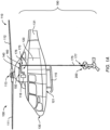
- Figure 1A and Figure 1B show an example of a rotary wing aircraft 100.
- the rotary wing aircraft may be a multicopter, a drone, or any other rotorcraft such as tiltable-wing, fixed-wing, or wingless aircraft.
- Aircraft 100 is exemplarily illustrated as a helicopter.
- helicopter helicopter
- the helicopter 100 is exemplarily embodied with a fuselage 120 and at least one multi-blade main rotor 110 for providing lift and forward or backward thrust during operation.
- the at least one multi-blade main rotor 110 illustratively comprises a plurality of rotor blades 111, 112.
- the rotor blades 111, 112 are mounted at an associated rotor head 113 to a rotor shaft, which rotates in operation of the helicopter 100 around the rotor shaft.
- the fuselage 120 may comprise a fuselage underside 121 that is illustratively connected to a landing gear 115.
- the landing gear 115 is exemplarily embodied as a skid-type landing gear.
- the fuselage 120 may define a nose region 130 that is arranged in front of the fuselage 120.
- the fuselage 120 also defines a tail boom 131, which is cut away and not shown in greater detail, for simplicity and clarity of the drawings.
- the helicopter 100 may provide equipment 160 such as an external load device (e.g., a hoist 170) that is secured to the fuselage 120 with a component 140.
- the component may be attached to a motor 116 via a power transmission system 150.
- the motor 116 may illustratively be arranged under the rotor head 113 and provide a rotational movement to the power transmission system 150.
- Power transmission system 150 may transform the rotational movement of the motor 116 into a circular movement of the component 140.
- An outward circular movement of the component 140 i.e., a circular movement of component 140 that moves equipment 160 away from helicopter 100
- an inward circular movement of the component 140 i.e., a circular movement of component 140 that moves equipment 160 closer to helicopter 100
- Helicopter 100 may include a load carrying assembly 190 for carrying a load.
- the load carrying assembly 190 may include a cargo cable 175 and a load engaging system 200.
- the cargo cable 175 may have a first end 176 that is attachable to the hoist 170 and a second end 177 that is attached to the modular load carrying apparatus 200. If desired, the hoist 170 may deploy and retrieve the cargo cable 175.
- modular load carrying apparatus 200 of Figures 2A to 4C may implement the load engaging system 200 of Figure 1A that is attached to the second end 177 of the cargo cable 175.
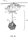
- Figure 1B is a diagram of an illustrative rotary wing aircraft 100 with a load carrying assembly 190 that is attached to a cargo hook arrangement 180 located at the fuselage underside 121.
- cargo hook arrangement 180 may be removably installed in the subfloor region of rotary wing aircraft 100 between a floor structure and a bottom shell.
- cargo hook arrangement 180 is mounted between two longerons, and longerons are connected to floor structure and bottom shell. If desired, cargo hook arrangement 180 may be mounted between two transversal frame components instead.
- a first end 176 of cargo cable 175 may be attachable to the cargo hook arrangement 180.
- cargo hook arrangement 180 may include a winch and the first end 176 of cargo cable 175 may be attachable to the winch.
- the winch may deploy cargo cable 175.
- a second end 177 of cargo cable 175 may be attached to modular load carrying apparatus 200.
- modular load carrying apparatus 200 of Figures 2A to 4C may implement the load engaging system 200 of Figure 1B that is attached to second end 177 of cargo cable 175.
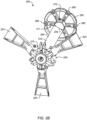
- FIG 2A is a diagram of an illustrative modular load carrying apparatus 200 with a removable seat-type platform 220 seen from above (i.e., as seen from the rotary wing aircraft 100 of Figure 1A or Figure 1B when the modular load carrying apparatus 200 is suspended from the rotary wing aircraft 100).
- the modular load carrying apparatus 200 may be used with the hoist 170 of Figure 1A or with the cargo hook arrangement 180 of Figure 1B .
- the modular load carrying apparatus 200 includes a tube 210.
- the tube 210 has a predetermined outer diameter 215 and first and second axial ends 211, 212.
- removable upholstery 240 may be removably installed to cover the outside of the tube 210.
- the removable upholstery 240 may have the shape of a tube, and the removable upholstery 240 may be slid over the first axial end 211 of the tube 210 to cover the outside of the tube 210.
- the modular load carrying apparatus 200 has first and second caps.
- the first cap is located inside the tube 210 at the first axial end 211 and adapted for being connected with the rotary wing aircraft.
- the first cap may provide an eyelet, and a shackle may attach the eyelet with a cargo cable (e.g., cargo cable 175 of Figure 1A or Figure 1B ).
- the second cap is located inside the tube 210 at the second axial end 212 and is described in more detail with reference to Figures 4A and 4C .
- the modular load carrying apparatus 200 includes, according to claim 1, at least two removable platforms.
- the at least two removable platforms are interchangeably installable on the tube 210.
- Each one of the two platforms has a predetermined inner diameter 225 that is greater than the predetermined outer diameter 215 of the tube 210.
- each one of the two platforms is adapted for being slidable over the first axial end 211 of the tube 210.
- the at least two removable platforms may be installed on the tube 210 at a given time.
- the one of the at least two removable platforms that is installed on the tube 210 is a seat-type platform 220.
- the seat-type platform 220 may include at least three seats 223. Illustratively, each one of the at least three seats 223 is attached to a carrier star.
- the carrier star shown in Figure 2A may receive up to six seats 223. However, a carrier star that is able to receive more than six seats 223 may be used, if desired.
- the seats 223 are evenly distributed around the tube 210.
- three seats 223 may be installed with an angle of 120° between each other.
- four seats 223 may be installed with an angle of 90° between each other on a suitable carrier star.
- six seats 223 may be installed with an angle of 60° between each other.
- the modular load carrying apparatus 200 may include a removable cover 250.
- the removable cover 250 may be adapted for being slidable over the first axial end 211 of the tube 210.
- the removable cover 250 may have a predetermined inner diameter that is greater than the predetermined outer diameter 215 of the tube 210.
- the removable cover 250 may include a plurality of safety lugs 260.
- the plurality of safety lugs 260 may be adapted for receiving means that secure a load on the seat-type platform 220.
- a person sitting on a seat 223 may be attached to one or more of the safety lugs 260 by means of personal protective equipment.
- a person sitting on a seat 223 may be attached with a harness, a safety line, and a snap hook or spring hook to one of the safety lugs 260.
- additional safety lugs may be provided on the upholstery 240 to ensure a redundant securing of each person.
- the removable cover 250 may be secured to the tube 210 and/or to the first cap.
- cover fasteners 270 may be adapted for securing the removable cover 250 to the tube 210 and to the first cap.
- the cover fasteners 270 may include safety bolts, quick release pins, or any other fasteners that may be removed and installed without a tool.
- at least two cover fasteners 270 and not more than four cover fasteners secure the removable cover 250 to the tube 210 and to the first cap.
- Figure 2B is a diagram of the illustrative modular load carrying apparatus of Figure 2A seen from below (i.e., as seen from the ground when the rotary wing aircraft 100 of Figure 1A or Figure 1B with the suspended modular load carrying apparatus 200 is hovering over the point of view).
- the removable cover 250 may have a predetermined inner diameter 255 that is greater than the predetermined outer diameter of the tube 210.
- the removable cover 250 may be adapted for being slidable over the first axial end 211 of the tube 210.
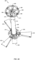
- FIG 3 is a diagram of an illustrative modular load carrying apparatus 200 with a removable net-type platform 230.
- the modular load carrying apparatus 200 may be used with the hoist 170 of Figure 1A or with the cargo hook arrangement 180 of Figure 1B .
- the modular load carrying apparatus 200 includes a tube 210.
- the tube 210 has a predetermined outer diameter 215 and first and second axial ends 211, 212. If desired, removable upholstery 240 may be removably installed to cover the outside of the tube 210.
- the modular load carrying apparatus 200 has first and second caps.
- the first cap is located inside the tube 210 at the first axial end 211 and adapted for being connected with the rotary wing aircraft.
- the first cap may provide an eyelet, and a shackle may attach the eyelet with a cargo cable (e.g., cargo cable 175 of Figure 1A or Figure 1B ).
- the second cap is be located inside the tube 210 at the second axial end 212 and is described in more detail with reference to Figures 4A and 4C .
- the modular load carrying apparatus 200 includes at least two removable platforms that are interchangeably installable on the tube 210. However, only one of the at least two removable platforms may be installed on the tube 210 at a given time. As shown in Figure 3 , the one of the at least two removable platforms that is installed on the tube 210 is a net-type platform 230.
- the net-type platform 230 may include at least six carrier beams 236.
- each one of the at least six carrier beams 236 is attached to a carrier star.
- the carrier star shown in Figure 3 may receive up to six carrier beams 236. However, a carrier star that is able to receive more than six carrier beams 236 may be used, if desired.
- the carrier beams 236 are evenly distributed around the tube 210.
- six carrier beams 236 may be installed with an angle of 60° between each other.
- each one of the at least six carrier beams 236 may be foldable. In the folded position, the carrier beams 236 may be secured by a fastener that prevents the carrier beams 236 from returning from the folded position to an unfolded position.
- a fastener with a quick release buckle such as a side release buckle, a push button release buckle, an end button release buckle, or another speciality release buckle may secure a carrier beam 236 to the tube 210 in the folded position.
- a fastener may be attached to the removable upholstery 240, if desired.
- the carrier beam 236 When moving a carrier beam 236 from the folded position to an unfolded position, the carrier beam 236 may be rotated downward by approximately 90° from its stored position to its unfolded position around a carrier rotation axis, until the carrier beam 236 is approximately orthogonal relative to the tube 210. During the downward rotation of the carrier beam 236, a springloaded carrier locking device may glide on the carrier beam 236 and snap into a recess on the carrier beam 236 when the carrier beam 236 is fully unfolded.
- the net-type platform 230 may be able to stand safely on the ground.
- the net-type platform 230 may stand on ground supports that are mounted on the lower side of each one of the carrier beams 236.
- the net-type platform 230 may include nets 233 between the at least six carrier beams 236.
- the net 233 may be stretched between the carrier beams 236.
- net holder bolts may fix a net 233 to a carrier beam 236.
- the net holder bolts may be passed through downwardly oriented loops that are installed at the middle plane of each carrier beam 236.
- the net holder bolts may be fed through drill holes on the outer flanges of the carrier beam 236 and secured with nuts.
- each carrier beam 236 On top of each carrier beam 236, a carrier cover may be attached. If desired, the carrier cover may be attached with a grip tape on its upper surface in order to guaranty a safe stand for the transport of people.
- the modular load carrying apparatus 200 with the net-type platform 230 may be adapted for transporting a predetermined number of people and their equipment at the same time.
- the modular load carrying apparatus 200 with the net-type platform 230 may be adapted for transporting three people and equipment at the same time.
- the modular load carrying apparatus 200 with the net-type platform 230 may be adapted for transporting six people and equipment at the same time.
- the net-type platform 230 may have a predetermined inner diameter that is greater than the predetermined outer diameter 215 of the tube 210.
- the net-type platform 230 may be adapted for being slidable over the first axial end 211 of the tube 210.
- the modular load carrying apparatus 200 may include a removable cover 250.
- the removable cover 250 may be adapted for being slidable over the first axial end 211 of the tube 210.
- the removable cover 250 may have a predetermined inner diameter that is greater than the predetermined outer diameter 215 of the tube 210.
- the removable cover 250 may include a plurality of safety lugs 260.
- the plurality of safety lugs 260 may be adapted for receiving means that secure a load on the net-type platform 230.
- a person sitting on a net 233 or standing on a carrier beam 236 may be attached to one or more of the safety lugs 260 by means of personal protective equipment.
- a person sitting on a net 233 may be attached with a harness, a safety line, and a snap hook or spring hook to one of the safety lugs 260.
- additional safety lugs may be provided on the upholstery 240 to ensure a redundant securing of each person.
- the removable cover 250 may be secured to the tube 210 and/or to the first cap.
- cover fasteners 270 may be adapted for securing the removable cover 250 to the tube 210 and to the first cap.
- the cover fasteners 270 may include safety bolts, quick release pins, or any other fasteners that may be removed and installed without a tool.
- at least two cover fasteners 270 and not more than four cover fasteners secure the removable cover 250 to the tube 210 and to the first cap.
- Figure 4A is a cross sectional diagram of an illustrative modular load carrying apparatus 200 for a rotary wing aircraft (e.g., rotary wing aircraft 100 of Figure 1A or Figure 1B ).
- Figure 4B is a cross sectional diagram of a first axial end 211 of the illustrative modular load carrying apparatus 200 of Figure 4A
- Figure 4C is a cross sectional diagram of a second axial end 212 of the illustrative modular load carrying apparatus 200 of Figure 4A .
- the modular load carrying apparatus 200 includes a tube 210.
- the tube 210 has a first predetermined outer diameter 215 and first and second axial ends 211, 212. If desired, the tube 210 may be adapted for serving as a floatation device.
- the modular load carrying apparatus 200 includes a first cap 410 that is located inside the tube 210 at the first axial end 211.
- the first cap 410 is adapted for being connected with the rotary wing aircraft.
- the first cap 410 may provide an eyelet 415, and a shackle 470 may attach the eyelet 415 with a cargo cable of the rotary wing aircraft.
- the modular load carrying apparatus 200 may include a removable cover 250.
- the removable cover 250 may have a second predetermined inner diameter 255 that is greater than the first predetermined outer diameter 215.
- the removable cover 250 may be adapted for being slidable over the first axial end 211 of the tube 210.
- cover fasteners 270 may be adapted for securing the removable cover 250 to the tube 210 and to the first cap 410.
- the cover fasteners 270 may include safety bolts, quick release pins, or any other fasteners that may be removed and installed without a tool.
- the cover fasteners 270 may secure the removable cover 250 to the tube 210 and to the first cap 410 on opposite sides of the tube 210.
- the modular load carrying apparatus 200 includes a second cap 420.
- the second cap 420 is located inside the tube 210 at the second axial end 212.
- the second cap 420 has a protrusion 422 that protrudes from the second axial end 212.
- the protrusion 422 has a second predetermined outer diameter 425 that is greater than the first predetermined outer diameter 215 (i.e., the outer diameter of the tube 210).
- the modular load carrying apparatus 200 includes at least first and second removable platforms 220, 230 that are interchangeably installable on the tube 210.
- the modular load carrying apparatus 200 may include at least a removable seat-type platform 220 as shown in Figures 2A and 2B and a removable net-type platform 230 as shown in Figure 3 .
- Each one of the at least first and second platforms 220, 230 has a first predetermined inner diameter 225 that is greater than the first predetermined outer diameter 215 (i.e., the outer diameter of the tube 210) and smaller than the second predetermined outer diameter 425 (i.e., the outer diameter of the protrusion 422).
- first predetermined outer diameter 215 i.e., the outer diameter of the tube 210
- second predetermined outer diameter 425 i.e., the outer diameter of the protrusion 422
- the modular load carrying apparatus 200 may include platform fasteners 430.
- the platform fasteners 430 may be adapted for securing each one of the at least first and second removable platforms 220, 230 to the tube 210 and to the second cap 420.
- the platform fasteners 430 may include safety bolts, quick release pins, or any other fasteners that may be removed and installed without a tool.
- at least two platform fasteners 430 and not more than four platform fasteners 430 secure the removable platforms 220, 230 to the tube 210 and to the second cap 420.
- the modular load carrying apparatus 200 may include a tension rod 440.
- the tension rod 440 may be spanned between the first cap 410 and the second cap 420.
- the tension rod 440 may be arranged inside the tube 210 between the first and second caps 410, 420.
- the tension rod 440 may be threaded at both ends.
- the tension rod 440 may have outer threads at both ends.
- the first cap 410 may include a threaded hole 447 into which one threaded end of the tension rod 440 is screwed.
- the second cap 420 may have a bore hole.
- the tension rod 440 may be put through the bore hole, and a tension rod fastener 445 such as a nut 445 may be screwed onto the other threaded end of the tension rod 440 (e.g., as shown in Figure 4A and 4C ), thereby spanning the tension rod 440 between the first and second caps 410, 420 as shown in Figure 4A .
- the tube 210 is clamped between the first and second caps 410, 420 by means of the tension rod 440.
- the pretension of the tension rod 440 respectively the clamp force of the tube 210 may be adjusted by the tension rod fastener 445, if desired.
- the tension rod 440 may transfer tension loads from the removable platform 220, 230 via the second cap 420 towards the first cap 410.
- the first cap 410 may further transfer the tension loads via the eyelet 415 to the shackle 470 and from there through a cargo cable (e.g., cargo cable 175 of Figures 1A or 1B ) to a hoist (e.g., hoist 170 of Figure 1A ) or cargo hook arrangement (e.g., cargo hook arrangement 180 of Figure 1B ).
- a cargo cable e.g., cargo cable 175 of Figures 1A or 1B
- a hoist e.g., hoist 170 of Figure 1A
- cargo hook arrangement e.g., cargo hook arrangement 180 of Figure 1B
- Figure 5A is a flowchart 500 showing illustrative operations of installing a removable platform such as the seat-type platform 220 of Figures 2A and 2B or the net-type platform 230 of Figure 3 on a modular load carrying apparatus such as the modular load carrying apparatus 200 of Figures 2A to 4C .
- the modular load carrying apparatus 200 may include platform fasteners 430, and includes a tube 210 that has a first predetermined outer diameter 215 and first and second axial ends 211, 212, a first cap 410 that is located inside the tube 210 at the first axial end 211, a second cap 420 that is located inside the tube 210 at the second axial end 212 and comprises a protrusion 422 that protrudes from the second axial end 212 and has a second predetermined outer diameter 425 that is greater than the first predetermined outer diameter 215, and at least first and second removable platforms 220, 230, wherein each one of the at least first and second platforms 220, 230 has a first predetermined inner diameter 225 that is greater than the first predetermined outer diameter 215 and smaller than the second predetermined outer diameter 425.
- an operator may select a platform among the at least first and second removable platforms, slide the selected platform over the first axial end of the tube until the selected platform reaches the protrusion that protrudes from the second axial end of the tube, and use the platform fasteners to attach the selected platform to the tube and to the second cap.
- an operator may select a platform 220, 230 among the at least first and second removable platforms 220, 230 (e.g., the seat-type platform 220 of Figure 2A and the net-type platform 230 of Figure 3 ) of Figure 4A , slide the selected platform 220, 230 over the first axial end 211 of the tube 210 until the selected platform 220, 230 reaches the protrusion 422 that protrudes from the second axial end 212 of the tube 210, and use the platform fasteners 430 to attach the selected platform 220, 230 to the tube 210 and to the second cap 420.
- a platform 220, 230 among the at least first and second removable platforms 220, 230 e.g., the seat-type platform 220 of Figure 2A and the net-type platform 230 of Figure 3
- slide the selected platform 220, 230 over the first axial end 211 of the tube 210 until the selected platform 220, 230 reaches the protrusion 422 that protrudes from the second axial end
- the modular load carrying apparatus 200 of Figure 4A may include removable upholstery (e.g., removable upholstery 240 of Figure 2A ). During an additional operation, the removable upholstery may be slid over the first axial end of the tube until the removable upholstery reaches the selected platform such that the removable upholstery covers the outside of the tube.
- removable upholstery e.g., removable upholstery 240 of Figure 2A
- the removable upholstery 240 of Figure 2A may be slid over the first axial end 211 of the tube 210 until the removable upholstery 240 reaches the selected platform 220, 230 such that the removable upholstery 240 covers the outside of the tube 210.
- the modular load carrying apparatus 200 of Figure 4A may further include cover fasteners 270 and a removable cover 250 that has a second predetermined inner diameter 255 that is greater than the first predetermined outer diameter 215.
- the removable cover may be installed at the first axial end of the tube, and the cover fasteners may be used to attach the removable cover to the tube and to the first cap.
- the removable cover 250 of Figure 4A may be installed at the first axial end 211 of the tube 210, and the cover fasteners 270 may be used to attach the removable cover 250 to the tube 210 and to the first cap 410.
- Figure 5B is a flowchart 590 showing illustrative operations of removing a removable platform such as the seat-type platform 220 of Figures 2A and 2B or the net-type platform 230 of Figure 3 from the modular load carrying apparatus 200 described with reference to Figure 5A .
- an operator may remove the cover fasteners to detach the removable cover from the tube and the first cap. The operator may then remove the removable cover from the first axial end of the tube.
- an operator may remove the cover fasteners 270 of Figure 4A to detach the removable cover 250 from the tube 210 and the first cap 410, and remove the removable cover 250 from the first axial end 211 of the tube 210.
- the operator may remove the removable upholstery from the outside of the tube by sliding the removable upholstery over the first axial end of the tube.
- the operator may remove the removable upholstery 240 of Figure 2A from the outside of the tube 210 by sliding the removable upholstery 240 over the first axial end 211 of the tube 210.
- the operator may remove the platform fasteners to detach the selected platform from the tube and the second cap, and, during operation 580, remove the selected platform from the modular load carrying apparatus by sliding the selected platform from the second axial end of the tube over the first axial end of the tube.
- the operator may remove the platform fasteners 430 of Figure 4A to detach the selected platform 220, 230 from the tube 210 and the second cap 310, and remove the selected platform 220, 230 from the modular load carrying apparatus 200 by sliding the selected platform 220, 230 from the second axial end 212 of the tube 210 over the first axial end 211 of the tube 210.
- hoist 170 of Figure 1A and cargo hook arrangement 180 of Figure 1B are shown to include a winch and the first end 176 of cargo cable 175 may be attachable to the winch.
- the winch may be part of the load carrying assembly 190 instead, and hoist 170 as well as cargo hook arrangement 180 may be adapted to receive the winch.
Description
- The present embodiments relate to a modular load carrying apparatus and, more particularly, to a modular load carrying apparatus as per claims 1-9 for a rotary wing aircraft. The present embodiments further relate to a method of operating a modular load carrying apparatus as per claims 10-15.
- Aircrafts and, more particularly, rotary wing aircrafts such as e.g. helicopters are commonly used to perform aerial transportation and delivery tasks, including passenger transport, disaster relief, or carrying all kind of external loads. By way of example, rotary wing aircrafts are used to transport and deliver loads to mountainous regions in general and, more specifically, to mountainous regions where no roads exist or where roads cannot be used for transportation and delivery, e. g. due to extreme weather conditions in winter and so on.
- Furthermore, rotary wing aircrafts are used for transportation and delivery of external loads such as passengers and equipment in the military sector or for rescue missions. In order to enable a rotary wing aircraft for transportation of an external load, the rotary wing aircraft is usually equipped with a hoist or lift mechanism.
- Conventionally, such a hoist or lift mechanism has a boom that is secured to the fuselage of the aircraft with an external system. The hoist may include a winch mechanism that is fixed to the boom and a rope or cable attached to the winch mechanism so as to be unwound from or wound into the winch mechanism to respectively descend or ascend.
- In many rotary wing aircrafts, the hoist mechanism is located above an access opening provided in the fuselage. This access opening allows people or objects to enter and exit the fuselage. Depending on the requirements of the mission and on the architecture of these rotary wing aircrafts, the opening access may be a side door, a rear door, a movable panel, or the like. Alternatively, a cargo hook arrangement may be installed underneath the rotary wing aircraft, and the opening access may be a floor trap.
- Generally, a load carrying apparatus is secured to the rope or cable and suspended from the rotary wing aircraft by means of the rope or cable. Thus, people and/or objects can be transported by the rotary wing aircraft while being carried by the load carrying apparatus.
- Document
WO 2019/091669 A1 describes a pod for transporting people between a barge and an oil platform, comprising a central pole and a plurality of arms, one end of each arm being mounted in an articulated manner on the central pole between a storage position in which each arm extends substantially parallel to the central pole, and a use position in which each arm extends substantially orthogonal to the central pole so as to form a support base onto which people can climb in a standing position, the central pole further comprising, at the head of same, a peripheral gripping member suitable for being gripped by the people during the journey. - Document
US 2005/0250396 A1 describes a compact rescue lift device adapted to be deployed from an elevated location, having a central spine with upper and lower portions, where the upper portion of the spine includes a means for coupling the device to a structure and the lower portion includes a plurality of seating surfaces which include both supporting and retaining portions, with the device also including a plurality of hand grips, where the device is adapted to carry multiple victims at a time. - Document
EP 1 646 562 A1 (US2006249330 ) describes a pod comprising a central pole having a support section which bears the ends of pivot-mounted arms. When retracted against the pole, opposing free sections of the arms are held in place by a removable locking device comprising an axially-mobile crown element which locks the arms in a radial manner. The aforementioned crown element is held in the locked position by means of a hysteresis effect. In this way, with the release of a compressed spring, the crown element can only be moved backwards out of the hold when the spring is additionally compressed by an external force, such as to release a mobile end stop element which impedes the action of the spring, and the backstop element is maintained in delicate equilibrium by the crown element. - Document
EP 1 100 720 A1 (US659883181 ) describes a device suspended to a carrier for rescuing people or equipment comprising a link between the carrier and a pod capable of being folded and unfolded formed by a frame associated with a flexible support. The frame comprises, fixed to the link, a central mast connected to mobile means bearing the flexible support, for folding and unfolding the mobile means and the flexible support about the central mast. - Document
US 3,476,339 A describes a device for lifting an individual from an area enshrouded with foliage, comprising: an upper inverted cup-shaped casing, a lower cup-shaped casing, collapsed telescoping tubular members joining said casings, a plurality of elongated sheet material elements pivotally mounted at their upper ends on the upper casing surrounding said tubular members with lower ends, of said elements extending within the upper portion of said lower casing, releasable means including a detent maintaining said tubular members in said collapsed position and the casings in positions retaining said elements within the cross-sectional areas of the casings whereby the device in a compact condition may move by gravity downwardly through foliage, said tubular members being extensible upon release of said detent whereby the casings may be moved away from each other, a seat member shiftable to a position substantially at right angles to said tubular members, and means for moving the sheet material elements to extended positions forming a canopy over said seat member to deflect foliage from an individual supported on said sheet member. - Document
US 3,467,346 A describes an air-ground rescue device for use with a cable suspended from a hovering aircraft, said device comprising seat defining means carried at the lower end of the cable, a protective shield assembly removably mounted to the cable above said seat defining means, said shield assembly including a cap having a laterally open side slot for receiving the suspended cable, at least two panels hingedly connected to said cap for movement toward and away from stowed positions wherein their corresponding side edges are arranged contiguous to one another. - Document
US 3,444,569 A describes an air-sea rescue device for use with a cable suspended from a hovering aircraft, said device comprising a shank portion having an upper end adapted for connection to a cable as aforesaid, and also having a lower end, at least one seat pivotally connected to said lower end for movement between a stowed position alongside said shank portion and a deployed position wherein said seat extends laterally outwardly at substantially 90 degrees with respect to said shank portion, a floatation collar for said shank portion to float the device when immersed in water, strap means associated with said shank upper end portion for securing a person to be rescued on said deployed seat, means for stowing said strap means to said shank upper end portion, said floatation collar being annular in cross section and extending from the lower end of said shank portion to a point spaced below the upper end thereof to permit ready removal of said stowed strap means without interfering with said collar. -
- However, all prior art documents lack a platform that is interchangeable between a seat-type and a net-type. Furthermore, any platform with foldable arms or seats uses straps or similar means that secure the foldable arms or seats in the deployed position. Moreover, all seat-type platforms lack means for preventing the arms or seats from rotating back from the unfolded position to a folded position.
- Based on the limitations and drawbacks of the prior art, an objective is to provide a modular load carrying apparatus for carrying a load with a rotary wing aircraft. The modular load carrying apparatus should have interchangeable platforms. These platforms should be lightweight, easy to install and to remove, and be foldable. Furthermore, the platforms should avoid the use of straps with which any equipment could become entangled.
- This objective is solved by a modular load carrying apparatus comprising the features of claim 1. More specifically, a modular load carrying apparatus for a rotary wing aircraft comprises a tube that has a first predetermined outer diameter and first and second axial ends; a first cap that is located inside the tube at the first axial end and adapted for being connected with the rotary wing aircraft; a second cap that is located inside the tube at the second axial end and comprises a protrusion that protrudes from the second axial end and has a second predetermined outer diameter that is greater than the first predetermined outer diameter; and at least first and second removable platforms that are interchangeably installable on the tube, wherein each one of the at least first and second platforms has a first predetermined inner diameter that is greater than the first predetermined outer diameter and smaller than the second predetermined outer diameter such that each one of the at least first and second removable platforms is adapted for being slidable over the first axial end of the tube and restrained by the second axial end of the tube.
- The inventive modular load carrying apparatus with interchangeable platforms complies with the latest amendments of the Federal Acquisition Regulation (FAR) requirements and military standards.
- The whole weight of the net-type and seat-type platforms is very low because just the net assembly and the seat assembly are exchanged and all the other parts of the modular load carrying apparatus such as, for example, the tube and the docking ring can be used for both configurations.
- The operational benefit of the modular load carrying apparatus with interchangeable platforms is significant. As an example, several people can be brought inside a rotary wing aircraft such as a helicopter (e.g., with the seat-type platform) at the same time. As another example, several people and equipment or cargo can be transported outside a helicopter (e.g., with the net-type platform).
- The modular load carrying apparatus with the net-type platform is adapted to the operational size of a special forces team in terms of volume or weight. In contrast thereto, conventional products are usually oversized.
- Due to the large diameter of the tube, the required floatability of the modular load carrying apparatus on water may be achieved without additional floats. Placing a load carrying rod inside the tube may decouple the tension from bending loads and reduce the forces on the pipe.
- Contrary to conventional load carrying apparatuses, no connecting or suspension ropes are attached between the tube and the carrier beams of the platforms. Instead, the forces and moments are transferred from the carrier beams directly into the carrier star. As a result, tripping hazards are eliminated and the segmentation of the areas is avoided, which may enable the faster execution of missions.
- The modular load carrying apparatus provides for redundant securing means. In fact, transported people and/or equipment may be secured to the tube and to the docking ring, which leads to an increase in safety.
- The modular load carrying apparatus may quickly be changed from a seat-type platform to a net-type platform and vice versa. A single person without tools may perform this change in configuration.
- The carrier beams of the net-type platform provide stable support for sitting and/or standing compared to state-of-the-art products, where small tubes are installed and standing or sitting is only possible on the net.
- The modular load carrying apparatus may be used for airborne external transport of people and cargo on rotary wing aircrafts such as helicopters. Depending on the planned mission, the desired platform type (e.g., a seat-type or net-type platform) may be mounted to the modular load carrying apparatus in a short time.
- Integrated safety lugs on a docking ring may be used to secure people and/or cargo. A carrier arm of the seat-type or net-type platforms can be fixed in an unfolded position with a carrier locking device. Due to the carrier locking devices, the respective platforms may be able to stand safely on the ground without tipping over.
- According to one aspect, only one of the at least first and second removable platforms is installable on the tube at a given time.
- According to one aspect, the at least first and second removable platforms further comprise a seat-type platform with at least three seats.
- According to one aspect, the at least first and second removable platforms further comprise a net-type platform with at least six carrier beams and nets between the at least six carrier beams.
- According to one aspect, the modular load carrying apparatus further comprises removable upholstery that is removably installed to cover the outside of the tube.
- According to one aspect, the modular load carrying apparatus further comprises platform fasteners that are adapted for securing each one of the at least first and second removable platforms to the tube and to the second cap.
- According to one aspect, the modular load carrying apparatus further comprises a removable cover that has a second predetermined inner diameter that is greater than the first predetermined outer diameter and that is adapted for being slidable over the first axial end of the tube.
- According to one aspect, the removable cover further comprises a plurality of safety lugs that are adapted for receiving means that secure a load on the at least first and second removable platforms.
- According to one aspect, the modular load carrying apparatus further comprises cover fasteners that are adapted for securing the removable cover to the tube and to the first cap.
- Furthermore, a method of operating a modular load carrying apparatus, the modular load carrying apparatus comprising platform fasteners, a tube that has a first predetermined outer diameter and first and second axial ends, a first cap that is located inside the tube at the first axial end, a second cap that is located inside the tube at the second axial end and comprises a protrusion that protrudes from the second axial end and has a second predetermined outer diameter that is greater than the first predetermined outer diameter, and at least first and second removable platforms, wherein each one of the at least first and second platforms has a first predetermined inner diameter that is greater than the first predetermined outer diameter and smaller than the second predetermined outer diameter, comprises selecting a platform among the at least first and second removable platforms; sliding the selected platform over the first axial end of the tube until the selected platform reaches the protrusion that protrudes from the second axial end of the tube; and using the platform fasteners to attach the selected platform to the tube and to the second cap.
- According to one aspect, the modular load carrying apparatus further comprises removable upholstery, and the method further comprises sliding the removable upholstery over the first axial end of the tube until the removable upholstery reaches the selected platform such that the removable upholstery covers the outside of the tube.
- According to one aspect, the modular load carrying apparatus further comprises cover fasteners and a removable cover that has a second predetermined inner diameter that is greater than the first predetermined outer diameter, and the method further comprises installing the removable cover at the first axial end of the tube; and using the cover fasteners to attach the removable cover to the tube and to the first cap.
- According to one aspect, the method further comprises removing the cover fasteners to detach the removable cover from the tube and the first cap; and removing the removable cover from the first axial end of the tube.
- According to one aspect, the modular load carrying apparatus further comprises removable upholstery that covers the outside of the tube, and the method further comprises removing the removable upholstery from the outside of the tube by sliding the removable upholstery over the first axial end of the tube.
- According to one aspect, the method further comprises removing the platform fasteners to detach the selected platform from the tube and the second cap; and removing the selected platform from the modular load carrying apparatus by sliding the selected platform from the second axial end of the tube over the first axial end of the tube.
- Embodiments are outlined by way of example in the following description with reference to the attached drawings. In these attached drawings, identical or identically functioning components and elements are labeled with identical reference numbers and characters and are, consequently, only described once in the following description.
-
Figure 1A is a diagram of an illustrative rotary wing aircraft with a modular load carrying apparatus that is attached to a hoist mechanism located above an access opening in the fuselage in accordance with some embodiments, -
Figure 1B is a diagram of an illustrative rotary wing aircraft with a modular load carrying apparatus that is attached to a cargo hook arrangement located at the underside of the fuselage in accordance with some embodiments, -
Figure 2A is a diagram of an illustrative modular load carrying apparatus with a seat-type platform seen from above in accordance with some embodiments, -
Figure 2B is a diagram of the illustrative modular load carrying apparatus ofFigure 2A seen from below in accordance with some embodiments, -
Figure 3 is a diagram of an illustrative modular load carrying apparatus with a net-type platform in accordance with some embodiments, -
Figure 4A is a cross sectional diagram of an illustrative modular load carrying apparatus in accordance with some embodiments, -
Figure 4B is a cross sectional diagram of a first axial end of the illustrative modular load carrying apparatus ofFigure 4A in accordance with some embodiments, -
Figure 4C is a cross sectional diagram of a second axial end of the illustrative modular load carrying apparatus ofFigure 4A in accordance with some embodiments, -
Figure 5A is a flowchart showing illustrative operations of installing a removable platform on a modular load carrying apparatus in accordance with some embodiments, and -
Figure 5B is a flowchart showing illustrative operations of removing a removable platform from a modular load carrying apparatus in accordance with some embodiments. - Exemplary embodiments may be included in any rotary wing aircraft that is adapted for vertical take-off and landing.
Figure 1A andFigure 1B show an example of arotary wing aircraft 100. The rotary wing aircraft may be a multicopter, a drone, or any other rotorcraft such as tiltable-wing, fixed-wing, or wingless aircraft.Aircraft 100 is exemplarily illustrated as a helicopter. Thus, for purposes of simplicity and clarity,aircraft 100 is hereinafter referred to as "helicopter" 100. - As shown in
Figure 1A , thehelicopter 100 is exemplarily embodied with afuselage 120 and at least one multi-blademain rotor 110 for providing lift and forward or backward thrust during operation. - The at least one multi-blade
main rotor 110 illustratively comprises a plurality ofrotor blades rotor blades rotor head 113 to a rotor shaft, which rotates in operation of thehelicopter 100 around the rotor shaft. - Illustratively, the
fuselage 120 may comprise afuselage underside 121 that is illustratively connected to alanding gear 115. Thelanding gear 115 is exemplarily embodied as a skid-type landing gear. - The
fuselage 120 may define anose region 130 that is arranged in front of thefuselage 120. Thefuselage 120 also defines atail boom 131, which is cut away and not shown in greater detail, for simplicity and clarity of the drawings. - If desired, the
helicopter 100 may provideequipment 160 such as an external load device (e.g., a hoist 170) that is secured to thefuselage 120 with acomponent 140. The component may be attached to amotor 116 via apower transmission system 150. Themotor 116 may illustratively be arranged under therotor head 113 and provide a rotational movement to thepower transmission system 150. -
Power transmission system 150 may transform the rotational movement of themotor 116 into a circular movement of thecomponent 140. An outward circular movement of the component 140 (i.e., a circular movement ofcomponent 140 that movesequipment 160 away from helicopter 100) may deploy theequipment 160, whereas an inward circular movement of the component 140 (i.e., a circular movement ofcomponent 140 that movesequipment 160 closer to helicopter 100) may retrieve theequipment 160. -
Helicopter 100 may include aload carrying assembly 190 for carrying a load. Theload carrying assembly 190 may include acargo cable 175 and aload engaging system 200. Illustratively, thecargo cable 175 may have afirst end 176 that is attachable to the hoist 170 and asecond end 177 that is attached to the modularload carrying apparatus 200. If desired, the hoist 170 may deploy and retrieve thecargo cable 175. - Illustratively, modular
load carrying apparatus 200 ofFigures 2A to 4C may implement theload engaging system 200 ofFigure 1A that is attached to thesecond end 177 of thecargo cable 175. -
Figure 1B is a diagram of an illustrativerotary wing aircraft 100 with aload carrying assembly 190 that is attached to acargo hook arrangement 180 located at thefuselage underside 121. Illustratively,cargo hook arrangement 180 may be removably installed in the subfloor region ofrotary wing aircraft 100 between a floor structure and a bottom shell. - By way of example,
cargo hook arrangement 180 is mounted between two longerons, and longerons are connected to floor structure and bottom shell. If desired,cargo hook arrangement 180 may be mounted between two transversal frame components instead. - A
first end 176 ofcargo cable 175 may be attachable to thecargo hook arrangement 180. For example,cargo hook arrangement 180 may include a winch and thefirst end 176 ofcargo cable 175 may be attachable to the winch. When the first end of 176 ofcargo cable 175 is attached to the winch, the winch may deploycargo cable 175. - A
second end 177 ofcargo cable 175 may be attached to modularload carrying apparatus 200. Illustratively, modularload carrying apparatus 200 ofFigures 2A to 4C may implement theload engaging system 200 ofFigure 1B that is attached tosecond end 177 ofcargo cable 175. -
Figure 2A is a diagram of an illustrative modularload carrying apparatus 200 with a removable seat-type platform 220 seen from above (i.e., as seen from therotary wing aircraft 100 ofFigure 1A orFigure 1B when the modularload carrying apparatus 200 is suspended from the rotary wing aircraft 100). The modularload carrying apparatus 200 may be used with the hoist 170 ofFigure 1A or with thecargo hook arrangement 180 ofFigure 1B . - According to claim 1, the modular
load carrying apparatus 200 includes atube 210. Thetube 210 has a predeterminedouter diameter 215 and first and second axial ends 211, 212. If desired,removable upholstery 240 may be removably installed to cover the outside of thetube 210. For example, theremovable upholstery 240 may have the shape of a tube, and theremovable upholstery 240 may be slid over the firstaxial end 211 of thetube 210 to cover the outside of thetube 210. - Furthermore, the modular
load carrying apparatus 200 has first and second caps. The first cap is located inside thetube 210 at the firstaxial end 211 and adapted for being connected with the rotary wing aircraft. For example, the first cap may provide an eyelet, and a shackle may attach the eyelet with a cargo cable (e.g.,cargo cable 175 ofFigure 1A orFigure 1B ). - The second cap is located inside the
tube 210 at the secondaxial end 212 and is described in more detail with reference toFigures 4A and4C . - The modular
load carrying apparatus 200 includes, according to claim 1, at least two removable platforms. The at least two removable platforms are interchangeably installable on thetube 210. - Each one of the two platforms has a predetermined
inner diameter 225 that is greater than the predeterminedouter diameter 215 of thetube 210. Thus, each one of the two platforms is adapted for being slidable over the firstaxial end 211 of thetube 210. - However, only one of the at least two removable platforms may be installed on the
tube 210 at a given time. As shown inFigure 2A , the one of the at least two removable platforms that is installed on thetube 210 is a seat-type platform 220. - The seat-
type platform 220 may include at least threeseats 223. Illustratively, each one of the at least threeseats 223 is attached to a carrier star. The carrier star shown inFigure 2A may receive up to sixseats 223. However, a carrier star that is able to receive more than sixseats 223 may be used, if desired. - Preferably, the
seats 223 are evenly distributed around thetube 210. As an example, threeseats 223 may be installed with an angle of 120° between each other. As another example, fourseats 223 may be installed with an angle of 90° between each other on a suitable carrier star. As yet another example, sixseats 223 may be installed with an angle of 60° between each other. - Illustratively, the modular
load carrying apparatus 200 may include aremovable cover 250. Theremovable cover 250 may be adapted for being slidable over the firstaxial end 211 of thetube 210. Thus, theremovable cover 250 may have a predetermined inner diameter that is greater than the predeterminedouter diameter 215 of thetube 210. - By way of example, the
removable cover 250 may include a plurality of safety lugs 260. The plurality of safety lugs 260 may be adapted for receiving means that secure a load on the seat-type platform 220. For example, a person sitting on aseat 223 may be attached to one or more of the safety lugs 260 by means of personal protective equipment. - As an example, a person sitting on a
seat 223 may be attached with a harness, a safety line, and a snap hook or spring hook to one of the safety lugs 260. If desired, additional safety lugs may be provided on theupholstery 240 to ensure a redundant securing of each person. - Illustratively, the
removable cover 250 may be secured to thetube 210 and/or to the first cap. For example, coverfasteners 270 may be adapted for securing theremovable cover 250 to thetube 210 and to the first cap. - If desired, the
cover fasteners 270 may include safety bolts, quick release pins, or any other fasteners that may be removed and installed without a tool. Preferably, at least twocover fasteners 270 and not more than four cover fasteners secure theremovable cover 250 to thetube 210 and to the first cap. -
Figure 2B is a diagram of the illustrative modular load carrying apparatus ofFigure 2A seen from below (i.e., as seen from the ground when therotary wing aircraft 100 ofFigure 1A orFigure 1B with the suspended modularload carrying apparatus 200 is hovering over the point of view). - As shown in
Figure 2B , theremovable cover 250 may have a predeterminedinner diameter 255 that is greater than the predetermined outer diameter of thetube 210. Thus, theremovable cover 250 may be adapted for being slidable over the firstaxial end 211 of thetube 210. -
Figure 3 is a diagram of an illustrative modularload carrying apparatus 200 with a removable net-type platform 230. The modularload carrying apparatus 200 may be used with the hoist 170 ofFigure 1A or with thecargo hook arrangement 180 ofFigure 1B . - According to claim 1, the modular
load carrying apparatus 200 includes atube 210. Thetube 210 has a predeterminedouter diameter 215 and first and second axial ends 211, 212. If desired,removable upholstery 240 may be removably installed to cover the outside of thetube 210. - Furthermore, the modular
load carrying apparatus 200 has first and second caps. The first cap is located inside thetube 210 at the firstaxial end 211 and adapted for being connected with the rotary wing aircraft. For example, the first cap may provide an eyelet, and a shackle may attach the eyelet with a cargo cable (e.g.,cargo cable 175 ofFigure 1A orFigure 1B ). - The second cap is be located inside the
tube 210 at the secondaxial end 212 and is described in more detail with reference toFigures 4A and4C . - The modular
load carrying apparatus 200 includes at least two removable platforms that are interchangeably installable on thetube 210. However, only one of the at least two removable platforms may be installed on thetube 210 at a given time. As shown inFigure 3 , the one of the at least two removable platforms that is installed on thetube 210 is a net-type platform 230. - The net-
type platform 230 may include at least six carrier beams 236. Illustratively, each one of the at least sixcarrier beams 236 is attached to a carrier star. The carrier star shown inFigure 3 may receive up to six carrier beams 236. However, a carrier star that is able to receive more than sixcarrier beams 236 may be used, if desired. - Preferably, the carrier beams 236 are evenly distributed around the
tube 210. For example, sixcarrier beams 236 may be installed with an angle of 60° between each other. - By way of example, each one of the at least six
carrier beams 236 may be foldable. In the folded position, the carrier beams 236 may be secured by a fastener that prevents the carrier beams 236 from returning from the folded position to an unfolded position. - For example, a fastener with a quick release buckle such as a side release buckle, a push button release buckle, an end button release buckle, or another speciality release buckle may secure a
carrier beam 236 to thetube 210 in the folded position. Such a fastener may be attached to theremovable upholstery 240, if desired. - When moving a
carrier beam 236 from the folded position to an unfolded position, thecarrier beam 236 may be rotated downward by approximately 90° from its stored position to its unfolded position around a carrier rotation axis, until thecarrier beam 236 is approximately orthogonal relative to thetube 210. During the downward rotation of thecarrier beam 236, a springloaded carrier locking device may glide on thecarrier beam 236 and snap into a recess on thecarrier beam 236 when thecarrier beam 236 is fully unfolded. - When all
carrier beams 236 are unfolded the net-type platform 230 may be able to stand safely on the ground. For example, the net-type platform 230 may stand on ground supports that are mounted on the lower side of each one of the carrier beams 236. - Illustratively, the net-
type platform 230 may includenets 233 between the at least six carrier beams 236. When two neighboring carrier beams 236 are in the fully unfolded position, the net 233 may be stretched between the carrier beams 236. - Illustratively, several net holder bolts may fix a net 233 to a
carrier beam 236. For this purpose, the net holder bolts may be passed through downwardly oriented loops that are installed at the middle plane of eachcarrier beam 236. The net holder bolts may be fed through drill holes on the outer flanges of thecarrier beam 236 and secured with nuts. - On top of each
carrier beam 236, a carrier cover may be attached. If desired, the carrier cover may be attached with a grip tape on its upper surface in order to guaranty a safe stand for the transport of people. - Thus, the modular
load carrying apparatus 200 with the net-type platform 230 may be adapted for transporting a predetermined number of people and their equipment at the same time. As an example, the modularload carrying apparatus 200 with the net-type platform 230 may be adapted for transporting three people and equipment at the same time. As another example, the modularload carrying apparatus 200 with the net-type platform 230 may be adapted for transporting six people and equipment at the same time. - The net-
type platform 230 may have a predetermined inner diameter that is greater than the predeterminedouter diameter 215 of thetube 210. Thus, the net-type platform 230 may be adapted for being slidable over the firstaxial end 211 of thetube 210. - Illustratively, the modular
load carrying apparatus 200 may include aremovable cover 250. Theremovable cover 250 may be adapted for being slidable over the firstaxial end 211 of thetube 210. Thus, theremovable cover 250 may have a predetermined inner diameter that is greater than the predeterminedouter diameter 215 of thetube 210. - By way of example, the
removable cover 250 may include a plurality of safety lugs 260. The plurality of safety lugs 260 may be adapted for receiving means that secure a load on the net-type platform 230. For example, a person sitting on a net 233 or standing on acarrier beam 236 may be attached to one or more of the safety lugs 260 by means of personal protective equipment. - As an example, a person sitting on a net 233 may be attached with a harness, a safety line, and a snap hook or spring hook to one of the safety lugs 260. If desired, additional safety lugs may be provided on the
upholstery 240 to ensure a redundant securing of each person. - Illustratively, the
removable cover 250 may be secured to thetube 210 and/or to the first cap. For example, coverfasteners 270 may be adapted for securing theremovable cover 250 to thetube 210 and to the first cap. - If desired, the
cover fasteners 270 may include safety bolts, quick release pins, or any other fasteners that may be removed and installed without a tool. Preferably, at least twocover fasteners 270 and not more than four cover fasteners secure theremovable cover 250 to thetube 210 and to the first cap. -
Figure 4A is a cross sectional diagram of an illustrative modularload carrying apparatus 200 for a rotary wing aircraft (e.g.,rotary wing aircraft 100 ofFigure 1A orFigure 1B ).Figure 4B is a cross sectional diagram of a firstaxial end 211 of the illustrative modularload carrying apparatus 200 ofFigure 4A , andFigure 4C is a cross sectional diagram of a secondaxial end 212 of the illustrative modularload carrying apparatus 200 ofFigure 4A . - According to claim 1, the modular
load carrying apparatus 200 includes atube 210. Thetube 210 has a first predeterminedouter diameter 215 and first and second axial ends 211, 212. If desired, thetube 210 may be adapted for serving as a floatation device. - As shown in
Figure 4A andFigure 4B , the modularload carrying apparatus 200 includes afirst cap 410 that is located inside thetube 210 at the firstaxial end 211. Thefirst cap 410 is adapted for being connected with the rotary wing aircraft. For example, thefirst cap 410 may provide aneyelet 415, and ashackle 470 may attach theeyelet 415 with a cargo cable of the rotary wing aircraft. - Illustratively, the modular
load carrying apparatus 200 may include aremovable cover 250. Theremovable cover 250 may have a second predeterminedinner diameter 255 that is greater than the first predeterminedouter diameter 215. Thus, theremovable cover 250 may be adapted for being slidable over the firstaxial end 211 of thetube 210. - If desired, cover
fasteners 270 may be adapted for securing theremovable cover 250 to thetube 210 and to thefirst cap 410. Thecover fasteners 270 may include safety bolts, quick release pins, or any other fasteners that may be removed and installed without a tool. Preferably, thecover fasteners 270 may secure theremovable cover 250 to thetube 210 and to thefirst cap 410 on opposite sides of thetube 210. - As shown in
Figure 4A andFigure 4C , the modularload carrying apparatus 200 includes asecond cap 420. Thesecond cap 420 is located inside thetube 210 at the secondaxial end 212. - The
second cap 420 has aprotrusion 422 that protrudes from the secondaxial end 212. Theprotrusion 422 has a second predeterminedouter diameter 425 that is greater than the first predetermined outer diameter 215 (i.e., the outer diameter of the tube 210). - In accordance with claim 1, the modular
load carrying apparatus 200 includes at least first and secondremovable platforms tube 210. For example, the modularload carrying apparatus 200 may include at least a removable seat-type platform 220 as shown inFigures 2A and2B and a removable net-type platform 230 as shown inFigure 3 . - Each one of the at least first and
second platforms inner diameter 225 that is greater than the first predetermined outer diameter 215 (i.e., the outer diameter of the tube 210) and smaller than the second predetermined outer diameter 425 (i.e., the outer diameter of the protrusion 422). Thus, each one of the at least first and secondremovable platforms axial end 211 of thetube 210 and restrained by the secondaxial end 212 of thetube 210. - Illustratively, the modular
load carrying apparatus 200 may includeplatform fasteners 430. Theplatform fasteners 430 may be adapted for securing each one of the at least first and secondremovable platforms tube 210 and to thesecond cap 420. - The
platform fasteners 430 may include safety bolts, quick release pins, or any other fasteners that may be removed and installed without a tool. Preferably, at least twoplatform fasteners 430 and not more than fourplatform fasteners 430 secure theremovable platforms tube 210 and to thesecond cap 420. - Illustratively, the modular
load carrying apparatus 200 may include atension rod 440. Thetension rod 440 may be spanned between thefirst cap 410 and thesecond cap 420. For example, thetension rod 440 may be arranged inside thetube 210 between the first andsecond caps - Illustratively, the
tension rod 440 may be threaded at both ends. For example, thetension rod 440 may have outer threads at both ends. If desired, thefirst cap 410 may include a threadedhole 447 into which one threaded end of thetension rod 440 is screwed. - The
second cap 420 may have a bore hole. Thetension rod 440 may be put through the bore hole, and atension rod fastener 445 such as anut 445 may be screwed onto the other threaded end of the tension rod 440 (e.g., as shown inFigure 4A and4C ), thereby spanning thetension rod 440 between the first andsecond caps Figure 4A . - Thus, the
tube 210 is clamped between the first andsecond caps tension rod 440. The pretension of thetension rod 440 respectively the clamp force of thetube 210 may be adjusted by thetension rod fastener 445, if desired. - The
tension rod 440 may transfer tension loads from theremovable platform second cap 420 towards thefirst cap 410. Thefirst cap 410 may further transfer the tension loads via theeyelet 415 to theshackle 470 and from there through a cargo cable (e.g.,cargo cable 175 ofFigures 1A or1B ) to a hoist (e.g., hoist 170 ofFigure 1A ) or cargo hook arrangement (e.g.,cargo hook arrangement 180 ofFigure 1B ). -
Figure 5A is aflowchart 500 showing illustrative operations of installing a removable platform such as the seat-type platform 220 ofFigures 2A and2B or the net-type platform 230 ofFigure 3 on a modular load carrying apparatus such as the modularload carrying apparatus 200 ofFigures 2A to 4C . - As exemplarily shown in
Figure 4A , the modularload carrying apparatus 200 may includeplatform fasteners 430, and includes atube 210 that has a first predeterminedouter diameter 215 and first and second axial ends 211, 212, afirst cap 410 that is located inside thetube 210 at the firstaxial end 211, asecond cap 420 that is located inside thetube 210 at the secondaxial end 212 and comprises aprotrusion 422 that protrudes from the secondaxial end 212 and has a second predeterminedouter diameter 425 that is greater than the first predeterminedouter diameter 215, and at least first and secondremovable platforms second platforms inner diameter 225 that is greater than the first predeterminedouter diameter 215 and smaller than the second predeterminedouter diameter 425. - During
operations - For example, an operator may select a
platform removable platforms 220, 230 (e.g., the seat-type platform 220 ofFigure 2A and the net-type platform 230 ofFigure 3 ) ofFigure 4A , slide the selectedplatform axial end 211 of thetube 210 until the selectedplatform protrusion 422 that protrudes from the secondaxial end 212 of thetube 210, and use theplatform fasteners 430 to attach the selectedplatform tube 210 and to thesecond cap 420. - If desired, the modular
load carrying apparatus 200 ofFigure 4A may include removable upholstery (e.g.,removable upholstery 240 ofFigure 2A ). During an additional operation, the removable upholstery may be slid over the first axial end of the tube until the removable upholstery reaches the selected platform such that the removable upholstery covers the outside of the tube. - For example, the
removable upholstery 240 ofFigure 2A may be slid over the firstaxial end 211 of thetube 210 until theremovable upholstery 240 reaches the selectedplatform removable upholstery 240 covers the outside of thetube 210. - Illustratively, the modular
load carrying apparatus 200 ofFigure 4A may further includecover fasteners 270 and aremovable cover 250 that has a second predeterminedinner diameter 255 that is greater than the first predeterminedouter diameter 215. During an additional operation, the removable cover may be installed at the first axial end of the tube, and the cover fasteners may be used to attach the removable cover to the tube and to the first cap. - For example, the
removable cover 250 ofFigure 4A may be installed at the firstaxial end 211 of thetube 210, and thecover fasteners 270 may be used to attach theremovable cover 250 to thetube 210 and to thefirst cap 410. -
Figure 5B is aflowchart 590 showing illustrative operations of removing a removable platform such as the seat-type platform 220 ofFigures 2A and2B or the net-type platform 230 ofFigure 3 from the modularload carrying apparatus 200 described with reference toFigure 5A . - During
operations - For example, an operator may remove the
cover fasteners 270 ofFigure 4A to detach theremovable cover 250 from thetube 210 and thefirst cap 410, and remove theremovable cover 250 from the firstaxial end 211 of thetube 210. - During
operation 560, the operator may remove the removable upholstery from the outside of the tube by sliding the removable upholstery over the first axial end of the tube. - For example, the operator may remove the
removable upholstery 240 ofFigure 2A from the outside of thetube 210 by sliding theremovable upholstery 240 over the firstaxial end 211 of thetube 210. - During
operation 570, the operator may remove the platform fasteners to detach the selected platform from the tube and the second cap, and, duringoperation 580, remove the selected platform from the modular load carrying apparatus by sliding the selected platform from the second axial end of the tube over the first axial end of the tube. - For example, the operator may remove the
platform fasteners 430 ofFigure 4A to detach the selectedplatform tube 210 and the second cap 310, and remove the selectedplatform load carrying apparatus 200 by sliding the selectedplatform axial end 212 of thetube 210 over the firstaxial end 211 of thetube 210. - It should be noted that the above-described embodiments are merely described for illustration purposes, but not in order to restrict the present invention thereto. Instead, multiple modifications and variations of the presented embodiments are possible and should, therefore, also be considered as being part of the invention, if they fall within the scope of the appended claims.
- For example, hoist 170 of
Figure 1A andcargo hook arrangement 180 ofFigure 1B are shown to include a winch and thefirst end 176 ofcargo cable 175 may be attachable to the winch. However, the winch may be part of theload carrying assembly 190 instead, and hoist 170 as well ascargo hook arrangement 180 may be adapted to receive the winch. -
- 100
- rotary wing aircraft
- 110
- multi-blade main rotor
- 111, 112
- rotor blades
- 113
- rotor head
- 115
- landing gear
- 116
- motor
- 120
- fuselage
- 121
- fuselage underside
- 130
- nose region
- 131
- tail boom
- 140
- component
- 150
- power transmission system
- 160
- equipment
- 170
- hoist
- 175
- cargo cable
- 176
- first end of cargo cable
- 177
- second end of cargo cable
- 180
- cargo hook arrangement
- 190
- load carrying assembly
- 200
- modular load carrying apparatus
- 210
- tube
- 211, 212
- axial end
- 215
- outer diameter
- 220
- removable platform
- 223
- seat
- 225
- inner diameter
- 230
- removable platform
- 233
- net
- 236
- carrier beam
- 240
- removable upholstery
- 250
- removable cover
- 255
- inner diameter
- 260
- safety lug
- 270
- cover fastener
- 410
- cap
- 415
- eyelet
- 420
- cap
- 422
- protrusion
- 425
- outer diameter
- 430
- platform fastener
- 440
- tension rod
- 445
- tension rod fastener
- 447
- threaded hole
- 470
- shackle
- 500, 590
- method
- 510, 520, 530, 540, 550, 560, 570, 580
- operation
Claims (15)
- A modular load carrying apparatus (200) for a rotary wing aircraft (100), comprising:a tube (210) that has a first predetermined outer diameter (215) and first and second axial ends (211, 212);a first cap (410) that is located inside the tube (210) at the first axial end (211) and adapted for being connected with the rotary wing aircraft (100);a second cap (420) that is located inside the tube (210) at the second axial end (212) and comprises a protrusion (422) that protrudes from the second axial end (212) and has a second predetermined outer diameter (425) that is greater than the first predetermined outer diameter (215); andat least first and second removable platforms (220, 230) that are interchangeably installable on the tube (210), wherein each one of the at least first and second platforms (220, 230) has a first predetermined inner diameter (225) that is greater than the first predetermined outer diameter (215) and smaller than the second predetermined outer diameter (425) such that each one of the at least first and second removable platforms (220, 230) is adapted for being slidable over the first axial end (211) of the tube (210) and restrained by the second axial end (212) of the tube (210).
- The modular load carrying apparatus (200) of claim 1, wherein only one of the at least first and second removable platforms (220, 230) is installable on the tube (210) at a given time.
- The modular load carrying apparatus (200) of any one of the preceding claims, wherein the at least first and second removable platforms (220, 230) further comprise:
a seat-type platform (220) with at least three seats (223). - The modular load carrying apparatus (200) of any one of the preceding claims, wherein the at least first and second removable platforms (220, 230) further comprise:
a net-type platform (230) with at least six carrier beams (236) and nets (233) between the at least six carrier beams (236). - The modular load carrying apparatus (200) of any one of the preceding claims, further comprising:
removable upholstery (240) that is removably installed to cover the outside of the tube (210). - The modular load carrying apparatus (200) of any one of the preceding claims, further comprising:
platform fasteners (430) that are adapted for securing each one of the at least first and second removable platforms (220, 230) to the tube (210) and to the second cap (420). - The modular load carrying apparatus (200) of any one of the preceding claims, further comprising:
a removable cover (250) that has a second predetermined inner diameter (255) that is greater than the first predetermined outer diameter (215) and that is adapted for being slidable over the first axial end (211) of the tube (210). - The modular load carrying apparatus (200) of claim 7, wherein the removable cover (250) further comprises:
a plurality of safety lugs (260) that are adapted for receiving means that secure a load on the at least first and second removable platforms (220, 230). - The modular load carrying apparatus (200) of claim 7, further comprising:
cover fasteners (270) that are adapted for securing the removable cover (250) to the tube (210) and to the first cap (410). - A method (500) of operating a modular load carrying apparatus (200), the modular load carrying apparatus (200) comprising platform fasteners (430), a tube (210) that has a first predetermined outer diameter (215) and first and second axial ends (211, 212), a first cap (410) that is located inside the tube (210) at the first axial end (211), a second cap (420) that is located inside the tube (210) at the second axial end (212) and comprises a protrusion (422) that protrudes from the second axial end (212) and has a second predetermined outer diameter (425) that is greater than the first predetermined outer diameter (215), and at least first and second removable platforms (220, 230), wherein each one of the at least first and second platforms (220, 230) has a first predetermined inner diameter (225) that is greater than the first predetermined outer diameter (215) and smaller than the second predetermined outer diameter (425), the method comprising:selecting (510) a platform (220, 230) among the at least first and second removable platforms (220, 230);sliding (520) the selected platform (220, 230) over the first axial end (211) of the tube (210) until the selected platform (220, 230) reaches the protrusion (422) that protrudes from the second axial end (212) of the tube (210); andusing (530) the platform fasteners (430) to attach the selected platform (220, 230) to the tube (210) and to the second cap (420).
- The method (500) of claim 10, wherein the modular load carrying apparatus (200) further comprises removable upholstery (240), further comprising:
sliding the removable upholstery (240) over the first axial end (211) of the tube (210) until the removable upholstery (240) reaches the selected platform (220, 230) such that the removable upholstery (240) covers the outside of the tube (210). - The method (500) of claim 10, wherein the modular load carrying apparatus (200) further comprises cover fasteners (270) and a removable cover (250) that has a second predetermined inner diameter (255) that is greater than the first predetermined outer diameter (215), further comprising:installing the removable cover (250) at the first axial end (211) of the tube (210); andusing the cover fasteners (270) to attach the removable cover (250) to the tube (210) and to the first cap (410).
- The method (500) of claim 12, further comprising:removing (540) the cover fasteners (270) to detach the removable cover (250) from the tube (210) and the first cap (410); andremoving (550) the removable cover (250) from the first axial end (211) of the tube (210).
- The method (500) of claim 10, wherein the modular load carrying apparatus (200) further comprises removable upholstery (240) that covers the outside of the tube (210), further comprising:
removing (560) the removable upholstery (240) from the outside of the tube (210) by sliding the removable upholstery (240) over the first axial end (211) of the tube (210). - The method (500) of claim 10, further comprising:removing (570) the platform fasteners (430) to detach the selected platform (220, 230) from the tube (210) and the second cap (310); andremoving (580) the selected platform (220, 230) from the modular load carrying apparatus (200) by sliding the selected platform (220, 230) from the second axial end (212) of the tube (210) over the first axial end (211) of the tube (210).
Priority Applications (3)
| Application Number | Priority Date | Filing Date | Title |
|---|---|---|---|
| EP21400011.9A EP4101760B1 (en) | 2021-06-08 | 2021-06-08 | A modular load carrying apparatus with interchangeable platforms |
| CA3146214A CA3146214A1 (en) | 2021-06-08 | 2022-01-20 | A modular load carrying apparatus with interchangeable platforms |
| US17/666,178 US20220388659A1 (en) | 2021-06-08 | 2022-02-07 | Modular load carrying apparatus with interchangeable platforms |
Applications Claiming Priority (1)
| Application Number | Priority Date | Filing Date | Title |
|---|---|---|---|
| EP21400011.9A EP4101760B1 (en) | 2021-06-08 | 2021-06-08 | A modular load carrying apparatus with interchangeable platforms |
Publications (2)
| Publication Number | Publication Date |
|---|---|
| EP4101760A1 EP4101760A1 (en) | 2022-12-14 |
| EP4101760B1 true EP4101760B1 (en) | 2024-01-03 |
Family
ID=77168197
Family Applications (1)
| Application Number | Title | Priority Date | Filing Date |
|---|---|---|---|
| EP21400011.9A Active EP4101760B1 (en) | 2021-06-08 | 2021-06-08 | A modular load carrying apparatus with interchangeable platforms |
Country Status (3)
| Country | Link |
|---|---|
| US (1) | US20220388659A1 (en) |
| EP (1) | EP4101760B1 (en) |
| CA (1) | CA3146214A1 (en) |
Family Cites Families (9)
| Publication number | Priority date | Publication date | Assignee | Title |
|---|---|---|---|---|
| US3444569A (en) | 1967-06-21 | 1969-05-20 | Kaman Corp | Air-sea rescue device with flotation collar |
| US3467346A (en) | 1967-11-16 | 1969-09-16 | Kaman Corp | Air-ground rescue device including protective shield assembly therefor |
| US3476339A (en) | 1968-02-21 | 1969-11-04 | Billy Gene Pugh | Jungle recovery device |
| US5593113A (en) * | 1995-02-06 | 1997-01-14 | Cox; Donald P. | Methods and apparatus for selectively attaching and releasing multiple payloads suspended from an aircraft |
| US6189834B1 (en) * | 1995-02-06 | 2001-02-20 | Skyhook Technologies, Inc. | Collapsible cargo management system for transporting payloads suspended from aircraft |
| FR2782060B1 (en) * | 1998-08-06 | 2000-10-13 | Jean Francois Tardy | DEVICE SUSPENDED FROM A CARRIER FOR THE RECOVERY OF INDIVIDUALS OR MATERIALS |
| FR2857269B1 (en) * | 2003-07-09 | 2005-09-16 | Jean Francois Tardy | NACELLE WITH LOCKING OF DEPLOYABLE ARMS. |
| US20050250396A1 (en) | 2004-05-06 | 2005-11-10 | Hayles David H | Rescue lift |
| FR3073514B1 (en) | 2017-11-10 | 2021-01-01 | Escape Int | NACELLE FOR TRANSPORTING PEOPLE ON AN OIL PLATFORM |
-
2021
- 2021-06-08 EP EP21400011.9A patent/EP4101760B1/en active Active
-
2022
- 2022-01-20 CA CA3146214A patent/CA3146214A1/en active Pending
- 2022-02-07 US US17/666,178 patent/US20220388659A1/en active Pending
Also Published As
| Publication number | Publication date |
|---|---|
| US20220388659A1 (en) | 2022-12-08 |
| CA3146214A1 (en) | 2022-12-08 |
| EP4101760A1 (en) | 2022-12-14 |
Similar Documents
| Publication | Publication Date | Title |
|---|---|---|
| US10023313B2 (en) | Rope suspension device with at least one rope suspension module | |
| US7946530B1 (en) | Modular adaptive configured helicopter | |
| US6648101B2 (en) | Fall protection lanyard apparatus | |
| US5190250A (en) | Autonomous, heliborne-mobile construction/emergency pod system | |
| US4113207A (en) | Airborne rescue device | |
| US4108402A (en) | Aircraft emergency letdown system | |
| KR100632477B1 (en) | Device suspended to a carrier for rescuing people or equipment | |
| US6883640B2 (en) | Fall protection lanyard apparatus | |
| EP2976256B1 (en) | Helicopter external life raft pod | |
| WO2000076845A1 (en) | System for deployment and retrieval of airborne towed vehicles | |
| US20210393999A1 (en) | Rotorcraft fall restraint protection attach points and mechanism systems | |
| US6604712B2 (en) | Method for transferring a load from an airborne rotorcraft to an elevated structure | |
| EP3708870A1 (en) | A power transmission system | |
| EP4101760B1 (en) | A modular load carrying apparatus with interchangeable platforms | |
| EP4101761B1 (en) | A modular load carrying apparatus with a carrier star | |
| EP3915873B1 (en) | Aircraft capable of hovering and method for transporting a load suspended for such aircraft | |
| US20050087652A1 (en) | Emergency parachute system for helicopters | |
| US20230183044A1 (en) | Human and/or non-human cargo attachment device for use with a rotorcraft | |
| EP3932803B1 (en) | Load carrying assembly for a rotary wing aircraft | |
| AU2003264626B2 (en) | Device suspended to a carrier for rescuing people or equipment | |
| GB1054950A (en) | ||
| CZ307171B6 (en) | A parachute rescue system |
Legal Events
| Date | Code | Title | Description |
|---|---|---|---|
| PUAI | Public reference made under article 153(3) epc to a published international application that has entered the european phase |
Free format text: ORIGINAL CODE: 0009012 |
|
| STAA | Information on the status of an ep patent application or granted ep patent |
Free format text: STATUS: THE APPLICATION HAS BEEN PUBLISHED |
|
| STAA | Information on the status of an ep patent application or granted ep patent |
Free format text: STATUS: REQUEST FOR EXAMINATION WAS MADE |
|
| AK | Designated contracting states |
Kind code of ref document: A1 Designated state(s): AL AT BE BG CH CY CZ DE DK EE ES FI FR GB GR HR HU IE IS IT LI LT LU LV MC MK MT NL NO PL PT RO RS SE SI SK SM TR |
|
| 17P | Request for examination filed |
Effective date: 20221129 |
|
| RBV | Designated contracting states (corrected) |
Designated state(s): AL AT BE BG CH CY CZ DE DK EE ES FI FR GB GR HR HU IE IS IT LI LT LU LV MC MK MT NL NO PL PT RO RS SE SI SK SM TR |
|
| P01 | Opt-out of the competence of the unified patent court (upc) registered |
Effective date: 20230530 |
|
| REG | Reference to a national code |
Ref country code: DE Ref legal event code: R079 Ref document number: 602021008325 Country of ref document: DE Free format text: PREVIOUS MAIN CLASS: B64D0001220000 Ipc: B64U0101600000 Ref country code: DE Ref legal event code: R079 Free format text: PREVIOUS MAIN CLASS: B64D0001220000 Ipc: B64U0101600000 |
|
| GRAP | Despatch of communication of intention to grant a patent |
Free format text: ORIGINAL CODE: EPIDOSNIGR1 |
|
| STAA | Information on the status of an ep patent application or granted ep patent |
Free format text: STATUS: GRANT OF PATENT IS INTENDED |
|
| INTG | Intention to grant announced |
Effective date: 20231018 |
|
| RIC1 | Information provided on ipc code assigned before grant |
Ipc: B64D 1/22 20060101ALI20231006BHEP Ipc: B64D 1/08 20060101ALI20231006BHEP Ipc: B64U 101/60 20230101AFI20231006BHEP |
|
| GRAS | Grant fee paid |
Free format text: ORIGINAL CODE: EPIDOSNIGR3 |
|
| GRAA | (expected) grant |
Free format text: ORIGINAL CODE: 0009210 |
|
| STAA | Information on the status of an ep patent application or granted ep patent |
Free format text: STATUS: THE PATENT HAS BEEN GRANTED |
|
| AK | Designated contracting states |
Kind code of ref document: B1 Designated state(s): AL AT BE BG CH CY CZ DE DK EE ES FI FR GB GR HR HU IE IS IT LI LT LU LV MC MK MT NL NO PL PT RO RS SE SI SK SM TR |
|
| REG | Reference to a national code |
Ref country code: GB Ref legal event code: FG4D |
|
| REG | Reference to a national code |
Ref country code: CH Ref legal event code: EP |
|
| REG | Reference to a national code |
Ref country code: DE Ref legal event code: R096 Ref document number: 602021008325 Country of ref document: DE |
|
| REG | Reference to a national code |
Ref country code: IE Ref legal event code: FG4D |