EP4116246B1 - Winding machine with an improved suction and waste collection system and a control method thereof - Google Patents
Winding machine with an improved suction and waste collection system and a control method thereof Download PDFInfo
- Publication number
- EP4116246B1 EP4116246B1 EP22174085.5A EP22174085A EP4116246B1 EP 4116246 B1 EP4116246 B1 EP 4116246B1 EP 22174085 A EP22174085 A EP 22174085A EP 4116246 B1 EP4116246 B1 EP 4116246B1
- Authority
- EP
- European Patent Office
- Prior art keywords
- waste
- valve
- winding machine
- suction
- evacuation
- Prior art date
- Legal status (The legal status is an assumption and is not a legal conclusion. Google has not performed a legal analysis and makes no representation as to the accuracy of the status listed.)
- Active
Links
Images


Classifications
-
- B—PERFORMING OPERATIONS; TRANSPORTING
- B65—CONVEYING; PACKING; STORING; HANDLING THIN OR FILAMENTARY MATERIAL
- B65H—HANDLING THIN OR FILAMENTARY MATERIAL, e.g. SHEETS, WEBS, CABLES
- B65H54/00—Winding, coiling, or depositing filamentary material
- B65H54/70—Other constructional features of yarn-winding machines
- B65H54/702—Arrangements for confining or removing dust
-
- B—PERFORMING OPERATIONS; TRANSPORTING
- B65—CONVEYING; PACKING; STORING; HANDLING THIN OR FILAMENTARY MATERIAL
- B65H—HANDLING THIN OR FILAMENTARY MATERIAL, e.g. SHEETS, WEBS, CABLES
- B65H54/00—Winding, coiling, or depositing filamentary material
- B65H54/70—Other constructional features of yarn-winding machines
- B65H54/707—Suction generating system
-
- B—PERFORMING OPERATIONS; TRANSPORTING
- B01—PHYSICAL OR CHEMICAL PROCESSES OR APPARATUS IN GENERAL
- B01D—SEPARATION
- B01D46/00—Filters or filtering processes specially modified for separating dispersed particles from gases or vapours
- B01D46/10—Particle separators, e.g. dust precipitators, using filter plates, sheets or pads having plane surfaces
-
- B—PERFORMING OPERATIONS; TRANSPORTING
- B08—CLEANING
- B08B—CLEANING IN GENERAL; PREVENTION OF FOULING IN GENERAL
- B08B15/00—Preventing escape of dirt or fumes from the area where they are produced; Collecting or removing dirt or fumes from that area
- B08B15/04—Preventing escape of dirt or fumes from the area where they are produced; Collecting or removing dirt or fumes from that area from a small area, e.g. a tool
-
- B—PERFORMING OPERATIONS; TRANSPORTING
- B08—CLEANING
- B08B—CLEANING IN GENERAL; PREVENTION OF FOULING IN GENERAL
- B08B5/00—Cleaning by methods involving the use of air flow or gas flow
- B08B5/04—Cleaning by suction, with or without auxiliary action
-
- B—PERFORMING OPERATIONS; TRANSPORTING
- B65—CONVEYING; PACKING; STORING; HANDLING THIN OR FILAMENTARY MATERIAL
- B65H—HANDLING THIN OR FILAMENTARY MATERIAL, e.g. SHEETS, WEBS, CABLES
- B65H54/00—Winding, coiling, or depositing filamentary material
- B65H54/70—Other constructional features of yarn-winding machines
-
- B—PERFORMING OPERATIONS; TRANSPORTING
- B65—CONVEYING; PACKING; STORING; HANDLING THIN OR FILAMENTARY MATERIAL
- B65H—HANDLING THIN OR FILAMENTARY MATERIAL, e.g. SHEETS, WEBS, CABLES
- B65H2701/00—Handled material; Storage means
- B65H2701/30—Handled filamentary material
- B65H2701/31—Textiles threads or artificial strands of filaments
Definitions
- the present invention relates to a winding machine with an improved suction and waste collection system and a control method thereof.
- the present invention relates to a winding machine provided with an improved suction and waste collection system and a control method thereof.
- the invention refers to a yarn suction and collection system serving a bobbin preparer, i.e. a preliminary station for processing bobbins of yarn coming directly from the spinning machine or from an independent loading system (bulk).
- a bobbin preparer i.e. a preliminary station for processing bobbins of yarn coming directly from the spinning machine or from an independent loading system (bulk).
- the main purpose of the preparer is to prepare the bobbins for the following winding phase and it is equipped with a dedicated aeraulic system which is designed to intercept the yarn end of each bobbin by means of a nozzle and insert it inside the tube in order to facilitate the gripping of the yarn end by the winding unit during the unravelling phase.
- the bobbins are transferred on special plates by means of conveyor belts to the yarn end suction nozzle, which is connected by pipes to the aforementioned dedicated suction unit that generates the required vacuum.
- a strand collection box equipped with a filter to separate the strands from the air flow and prevent such strands from reaching the fan intake mouth.
- the box is emptied in a timed manner depending on the number of bobbins and the type of yarn.
- the emptying of the box is entrusted either to an operator, who manually removes the strands by opening the door of the filter box (and therefore stopping the vacuum device for obvious reasons of safety and accessibility) or to a centralized vacuum system which, by means of special aeraulic ducts, conveys the strands with pneumatic transport up to the filter housed in the head of the machine.
- the disadvantage is the inevitable drop in productivity of the yarn end search station related to the need to temporarily interrupt the aspiration of such yarn end.
- this interruption serves to make the box hermetic and thus allow the exclusive connection to the depression generated by the centralized vacuum device, thus making the evacuation of the strands possible.
- each filter is typically placed at the service of other utilities, which may be fixed (e.g. plate conveyor belt cleaning nozzles) or variable (e.g. bobbin cleaner) and which must be served independently of the operating conditions of the yarn end search nozzle. Solutions according to prior art are disclosed for example by DE 2644274 A1 .
- reference numeral 4 globally denotes a winding machine.
- the present invention relates to a winding machine provided with an improved suction and waste collection system and a control method thereof.
- the invention refers to a yarn suction and collection system serving a bobbin preparer, a preliminary station for processing bobbins of yarn coming directly from the spinning machine or from an independent loading system (bulk).
- the present invention is therefore intended to be applicable to a generic strand suction and collection system serving a winding machine.
- thread or single thread or continuous thread refers to a single filament or continuous filament (for example in the case of silk, artificial or synthetic fibres), while the term yarn refers to a group of fibrils of varying lengths that are paralleled and joined together by twisting.
- thread or single thread or continuous thread refers to a single filament or continuous filament (for example in the case of silk, artificial or synthetic fibres)
- yarn refers to a group of fibrils of varying lengths that are paralleled and joined together by twisting.
- one or the other term will be used indifferently, it being understood that the applications of the present invention are not limited to one or the other type.
- the winding machine 4 comprises a vacuum generating device 8 for generating an air stream containing winding waste, such as strands or dust.
- the vacuum generating device 8 is, for example, a centrifugal fan, which may be driven via inverter by a brushless or asynchronous three-phase electric motor.
- the winding machine 4 further comprises a suction nozzle 12 for said winding waste, connected by a dedicated pipe to a sleeve 16 having at least a first outlet 20.
- the winding machine 4 comprises a first evacuation duct 24 of said winding waste, and a first filtering device 28 having a first waste collection box 32.
- the surface of the first filtering device is made of micro-perforated steel sheet.
- the first filtering device 28 is connected to the vacuum generating device 8 by a first waste suction duct 36, which can be partialized by a first waste suction valve 40.
- the first filtering device 28 is connected to the first outlet 20 of the sleeve 16 by means of a first waste feed duct 44, provided with a first waste feed valve 48.
- the aforesaid first filtering device 28 is provided with a first outlet mouth 52 connected to the first waste collection box 32 and to the first waste evacuation duct 24.
- first waste evacuation valve 56 it is possible to partialize said first outlet mouth 52 by means of a first waste evacuation valve 56.
- the winding machine 4 comprises a control unit 58 operatively connected to said first waste suction valve 40, first waste feed valve 48 and first waste evacuation valve 56, so as to control the operation thereof, as described in more detail below.
- the winding machine 4 is provided with at least a first utility 34 fluidically connected to said first filtering device 28.
- At least one of said first waste suction valve 40, first waste feed valve 48 and first waste evacuation valves 56 is a pneumatically operated regulating shutter.
- At least one of said first waste suction valve 40, first waste feed valve 48 and first waste evacuation valves 56 is provided with dedicated cutting means (not shown) for performing yarn cutting to prevent unwanted yarn entanglement/accumulation.
- the sleeve 16 is provided with a second outlet 60, distinct from the first outlet 20.
- the winding machine 4 comprises a second filtering device 68 having a second waste collection box 72 connected to the vacuum generating device 8 by means of a second waste suction duct 76, which can be partialized by means of a second waste suction valve 80.
- the surface of the second filtering device 68 is composed of micro-perforated steel sheet.
- the second filtering device 68 is connected to the second outlet 60 of the sleeve 16 by means of a second waste feed duct 84, provided with a second waste feed valve 88.
- the aforesaid second filtering device 68 is provided with a second outlet mouth 92 connected to said second waste collection box 72 and to a second waste evacuation duct 64.
- Said control unit 58 is operatively connected to said second waste suction valve 80, second waste feed valve 88 and second evacuation valve 96, so as to control the operation thereof, as described in more detail below.
- the winding machine 4 is provided with at least one second utility 38 fluidically connected to said second filtering device 68.
- At least one of said second waste suction valve 80, second waste feed valve 88 and second waste evacuation valves 96 is a pneumatically operated regulating shutter.
- At least one out of said second waste suction valve 80, second waste feed valve 88 and second waste evacuation valves 96 is provided with dedicated cutting means (not shown) for performing yarn cutting to prevent unwanted yarn tangles/accumulation.
- the suction system of the winding machine 4 aspirates and collects the strands in one of said first 32 and second waste collection boxes 72, while the other waste collection box 72,32) is momentarily non-operational.
- the first waste feed valve 48 must be opened to serve the suction nozzle 12 and collect said waste.
- first waste suction valve 40 must be opened to serve the suction nozzle 12 and/or at least a first utility 34 fluidically connected to said first filtering device 28; lastly the first waste evacuation valve 56 must be closed.
- the second waste feed valve 88 must be closed so as not to disturb the flow of waste flowing into the first waste collection box 32, the second waste suction valve 80 must then be opened, to continue to serve a second utility 38 fluidically connected to said second filtering device 68, and lastly the second waste evacuation valve 96 must be closed.
- the first waste collection box 32 When the first waste collection box 32 reaches the maximum programmed filling level, it must first be made hermetic by carrying out the following operating steps in sequence.
- the first waste suction valve 40 is closed, the first waste feed valve 48 is closed, and the first waste evacuation valve 56 is opened and the evacuation of the waste is then carried out.
- the first waste evacuation valve 56 is then closed and lastly the first waste suction valve 40 is reopened to serve a first utility 34 fluidically connected to said first filtering device 28.
- the waste must be conveyed to the second waste collection box 72 to give continuity of service to the suction nozzle 12.
- the second waste feed valve 88 is opened, the second waste suction valve 80 is kept open, in order to continue serving a second utility 38 fluidically connected to said second filtering device 68, and lastly the second waste evacuation valve 96 is closed.
- the present invention makes it possible to overcome the drawbacks of the prior art.
- the present invention makes it possible to obtain continuity of the suction service of the yarn end search nozzle, which is always guaranteed for the bobbins, regardless of the unloading step of the strands.
Landscapes
- Engineering & Computer Science (AREA)
- Textile Engineering (AREA)
- Chemical & Material Sciences (AREA)
- Chemical Kinetics & Catalysis (AREA)
- Spinning Or Twisting Of Yarns (AREA)
- Spinning Methods And Devices For Manufacturing Artificial Fibers (AREA)
Description
- The present invention relates to a winding machine with an improved suction and waste collection system and a control method thereof.
- As is well known, automatic winding machines produce considerable quantities of strands, dust and waste, which must be suitably aspirated and evacuated. For this purpose, special suction devices are used (typically centrifugal fans) which remove the waste from the utilities involved and convey it to special collection boxes before subsequent removal, either manually or centrally, in order to avoid undesirable clogging/yarn accumulation and thus guarantee the correct operation of the machine.
- The present invention relates to a winding machine provided with an improved suction and waste collection system and a control method thereof. By way of a non-limiting example, the invention refers to a yarn suction and collection system serving a bobbin preparer, i.e. a preliminary station for processing bobbins of yarn coming directly from the spinning machine or from an independent loading system (bulk).
- The main purpose of the preparer is to prepare the bobbins for the following winding phase and it is equipped with a dedicated aeraulic system which is designed to intercept the yarn end of each bobbin by means of a nozzle and insert it inside the tube in order to facilitate the gripping of the yarn end by the winding unit during the unravelling phase. The bobbins are transferred on special plates by means of conveyor belts to the yarn end suction nozzle, which is connected by pipes to the aforementioned dedicated suction unit that generates the required vacuum.
- For obvious reasons due to the need to aspirate and collect the waste resulting from the pick-up of the yarn end on the spool side and from the corresponding cut made by the scissors on the nozzle, the use of a strand collection box equipped with a filter to separate the strands from the air flow and prevent such strands from reaching the fan intake mouth is a known method. Typically, the box is emptied in a timed manner depending on the number of bobbins and the type of yarn. Moreover, the emptying of the box is entrusted either to an operator, who manually removes the strands by opening the door of the filter box (and therefore stopping the vacuum device for obvious reasons of safety and accessibility) or to a centralized vacuum system which, by means of special aeraulic ducts, conveys the strands with pneumatic transport up to the filter housed in the head of the machine. In the case where there is only one yarn collection box serving the system the disadvantage is the inevitable drop in productivity of the yarn end search station related to the need to temporarily interrupt the aspiration of such yarn end.
- In the case of manual emptying, this temporary interruption of the suction is necessary to cancel the depression present in the box and allow the operator to open the door and remove the strands in safety.
- In the case of automatic emptying, this interruption serves to make the box hermetic and thus allow the exclusive connection to the depression generated by the centralized vacuum device, thus making the evacuation of the strands possible.
- In addition, each filter is typically placed at the service of other utilities, which may be fixed (e.g. plate conveyor belt cleaning nozzles) or variable (e.g. bobbin cleaner) and which must be served independently of the operating conditions of the yarn end search nozzle. Solutions according to prior art are disclosed for example by
DE 2644274 A1 . - The need is therefore felt to resolve the drawbacks and limitations mentioned with reference to the prior art.
- Such need is met by a winding machine according to claim 1 and by a winding machine control method according to claim 11.
- Further characteristics and advantages of the present invention will be more clearly comprehensible from the description given below of its preferred and non-limiting embodiments, wherein:
-
figure 1 shows a perspective view of a winding machine according to one embodiment of the present invention; -
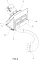
figure 2 shows a perspective view of a winding machine waste suction system according to the present invention; -
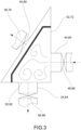
figure 3 is a partial cross-section view of the waste suction system infigure 2 ; -
figure 4 shows an operating diagram of the winding machine waste suction system infigure 2 . - The elements or parts of elements common to the embodiments described below will be indicated using the same reference numerals.
- With reference to the aforementioned figures,
reference numeral 4 globally denotes a winding machine. - As mentioned above, the present invention relates to a winding machine provided with an improved suction and waste collection system and a control method thereof. By way of a non-limiting example, the invention refers to a yarn suction and collection system serving a bobbin preparer, a preliminary station for processing bobbins of yarn coming directly from the spinning machine or from an independent loading system (bulk).
- The present invention is therefore intended to be applicable to a generic strand suction and collection system serving a winding machine.
- In addition, it should be noted that the term thread or single thread or continuous thread refers to a single filament or continuous filament (for example in the case of silk, artificial or synthetic fibres), while the term yarn refers to a group of fibrils of varying lengths that are paralleled and joined together by twisting. Hereinafter, one or the other term will be used indifferently, it being understood that the applications of the present invention are not limited to one or the other type.
- The
winding machine 4 comprises avacuum generating device 8 for generating an air stream containing winding waste, such as strands or dust. - The
vacuum generating device 8 is, for example, a centrifugal fan, which may be driven via inverter by a brushless or asynchronous three-phase electric motor. - The
winding machine 4 further comprises asuction nozzle 12 for said winding waste, connected by a dedicated pipe to asleeve 16 having at least afirst outlet 20. - Furthermore, the
winding machine 4 comprises afirst evacuation duct 24 of said winding waste, and a first filtering device 28 having a firstwaste collection box 32. - According to a possible embodiment, the surface of the first filtering device is made of micro-perforated steel sheet.
- The first filtering device 28 is connected to the
vacuum generating device 8 by a firstwaste suction duct 36, which can be partialized by a firstwaste suction valve 40. - The first filtering device 28 is connected to the
first outlet 20 of thesleeve 16 by means of a firstwaste feed duct 44, provided with a firstwaste feed valve 48. - Moreover, the aforesaid first filtering device 28 is provided with a first outlet mouth 52 connected to the first
waste collection box 32 and to the firstwaste evacuation duct 24. - Preferably, it is possible to partialize said first outlet mouth 52 by means of a first
waste evacuation valve 56. - Preferably, the
winding machine 4 comprises acontrol unit 58 operatively connected to said firstwaste suction valve 40, firstwaste feed valve 48 and firstwaste evacuation valve 56, so as to control the operation thereof, as described in more detail below. - Preferably, the
winding machine 4 is provided with at least afirst utility 34 fluidically connected to said first filtering device 28. - According to a possible embodiment, at least one of said first
waste suction valve 40, firstwaste feed valve 48 and firstwaste evacuation valves 56 is a pneumatically operated regulating shutter. - According to the invention, at least one of said first
waste suction valve 40, firstwaste feed valve 48 and firstwaste evacuation valves 56 is provided with dedicated cutting means (not shown) for performing yarn cutting to prevent unwanted yarn entanglement/accumulation. - According to a possible embodiment, the
sleeve 16 is provided with asecond outlet 60, distinct from thefirst outlet 20. - According to a possible embodiment, the
winding machine 4 comprises a second filtering device 68 having a secondwaste collection box 72 connected to thevacuum generating device 8 by means of a secondwaste suction duct 76, which can be partialized by means of a secondwaste suction valve 80. - For example, the surface of the second filtering device 68 is composed of micro-perforated steel sheet.
- The second filtering device 68 is connected to the
second outlet 60 of thesleeve 16 by means of a secondwaste feed duct 84, provided with a secondwaste feed valve 88. - The aforesaid second filtering device 68 is provided with a second outlet mouth 92 connected to said second
waste collection box 72 and to a secondwaste evacuation duct 64. - It is possible to partialize said second outlet mouth 92 by means of a second
waste evacuation valve 96. - Said
control unit 58 is operatively connected to said secondwaste suction valve 80, secondwaste feed valve 88 andsecond evacuation valve 96, so as to control the operation thereof, as described in more detail below. - According to a possible embodiment, the
winding machine 4 is provided with at least onesecond utility 38 fluidically connected to said second filtering device 68. - According to a possible embodiment, at least one of said second
waste suction valve 80, secondwaste feed valve 88 and secondwaste evacuation valves 96 is a pneumatically operated regulating shutter. - According to a possible embodiment, at least one out of said second
waste suction valve 80, secondwaste feed valve 88 and secondwaste evacuation valves 96 is provided with dedicated cutting means (not shown) for performing yarn cutting to prevent unwanted yarn tangles/accumulation.. - The functioning i.e. the control method, of a winding machine with an improved waste suction and collection system according to the present invention will now be described.
- In particular, under normal suction conditions, the suction system of the
winding machine 4 aspirates and collects the strands in one of said first 32 and secondwaste collection boxes 72, while the otherwaste collection box 72,32) is momentarily non-operational. - For this condition to be realized the first
waste feed valve 48 must be opened to serve thesuction nozzle 12 and collect said waste. - In addition, the first
waste suction valve 40 must be opened to serve thesuction nozzle 12 and/or at least afirst utility 34 fluidically connected to said first filtering device 28; lastly the firstwaste evacuation valve 56 must be closed. - In addition, the second
waste feed valve 88 must be closed so as not to disturb the flow of waste flowing into the firstwaste collection box 32, the secondwaste suction valve 80 must then be opened, to continue to serve asecond utility 38 fluidically connected to said second filtering device 68, and lastly the secondwaste evacuation valve 96 must be closed. - When the first
waste collection box 32 reaches the maximum programmed filling level, it must first be made hermetic by carrying out the following operating steps in sequence. - In particular, the first
waste suction valve 40 is closed, the firstwaste feed valve 48 is closed, and the firstwaste evacuation valve 56 is opened and the evacuation of the waste is then carried out. - The first
waste evacuation valve 56 is then closed and lastly the firstwaste suction valve 40 is reopened to serve afirst utility 34 fluidically connected to said first filtering device 28. - At the same time, the waste must be conveyed to the second
waste collection box 72 to give continuity of service to thesuction nozzle 12. - For this purpose, the second
waste feed valve 88 is opened, the secondwaste suction valve 80 is kept open, in order to continue serving asecond utility 38 fluidically connected to said second filtering device 68, and lastly the secondwaste evacuation valve 96 is closed. - At this point, the first
waste collection box 32, which was operational, becomes non-operational, and vice versa. - As may be appreciated from the description, the present invention makes it possible to overcome the drawbacks of the prior art.
- In particular, the present invention makes it possible to obtain continuity of the suction service of the yarn end search nozzle, which is always guaranteed for the bobbins, regardless of the unloading step of the strands.
- This increases the productivity of the yarn end search station and thus of the entire machine.
- Moreover, in the case of centralized unloading, it is possible to unload the collected strands more frequently, with a consequent reduction of the depression needed to evacuate them from the box, of the speed necessary to transport them towards the centralized filter, therefore of the installed power, of the overall energy consumption of the machine and of the noise produced by the depression generating devices.
- In addition, greater service reliability is achieved in the event of one of the two collection boxes becoming inoperative, e.g. due to the failure of one or more of the economisers.
- Finally, there is a reduction in the stress on the vacuum device associated with the stopping and starting phases.
- A person skilled in the art may make numerous modifications and variations to the solutions described above so as to satisfy contingent and specific requirements.
- The scope of protection of the present invention is defined by the following claims.
Claims (15)
- Winding machine (4) comprising:- a vacuum generating device (8) for generating an air stream containing winding waste, such as strands or dust,- a suction nozzle (12) for said winding waste, connected to a sleeve (16) having at least a first outlet (20),- a first evacuation duct (24) of said winding waste,- a first filtering device (28) having a first waste collection box (32) and being connected to the vacuum generating device (8) by a first waste suction duct (36), which can be partialized by a first waste suction valve (40),- the first filtering device (28) being connected to the first outlet (20) of the sleeve (16) by means of a first waste feed duct (44), provided with a first waste feed valve (48),- said first filtering device (28) being provided with a first outlet mouth (52) connected to the first waste collection box (32) and to the first waste evacuation duct (24), it being possible to partialize said first outlet mouth (52) by means of a first waste evacuation valve (56),- wherein the sleeve (16) of the suction nozzle (12) is provided with a second outlet (60), distinct from the first outlet (20), and wherein the winding machine (4) includes a second filtering device (68) having a second waste collection box (72) connected to the vacuum generating device (8) by means of a second waste suction duct (76), which can be partialized by means of a second waste suction valve (80),- the second filtering device (68) being connected to the second outlet (60) of the sleeve (16) by means of a second waste feed duct (84), provided with a second waste feed valve (88),- the aforesaid second filtering device (68) being provided with a second outlet mouth (92) connected to said second waste collection box (72) and to a second waste evacuation duct (64), it being possible to partialize the second outlet mouth (92) by means of a second waste evacuation valve (96),characterized in that
at least one of said first waste suction valve (40), first waste feed valve (48) and first waste evacuation valves (56) is provided with dedicated cutting means for performing yarn cutting to prevent unwanted yarn tangles/accumulation. - The winding machine (4) according to claim 1, wherein the winding machine (4) comprises a control unit (58) operatively connected to said first waste suction valve (40), first waste feed valve (48) and first waste evacuation valve (56), so as to control the operation thereof.
- The winding machine (4) according to claim 2, wherein said control unit (58) is operatively connected to said second waste suction valve (80), said second waste feed valve (88) and said second waste evacuation valve (92), so as to control the operation thereof.
- The winding machine (4) according to claim 1 or 2, wherein the winding machine (4) is provided with at least a first utility (34) fluidically connected to said first filtering device (28) and/or at least one second utility (38) fluidically connected to said second filtering device (68) .
- The winding machine (4) according to any of the claims from 1 to 4, wherein at least one of said first waste suction valve (40), first waste feed valve (48) and first waste evacuation valves (56) is a pneumatically operated regulating shutter.
- The winding machine (4) according to any of the claims from 1 to 5, wherein at least one of said second waste suction valve (80), second waste feed valve (88) and second waste evacuation valves (96) is a pneumatically operated regulating shutter.
- The winding machine (4) according to any of the claims from 1 to 6, wherein at least one out of said second waste suction valve (80), second waste feed valve (88) and second waste evacuation valves (92) is provided with dedicated cutting means for performing yarn cutting to prevent unwanted yarn tangles/accumulation.
- The winding machine (4) according to any of the claims from 1 to 7, wherein the surface of the first filtering device (28) comprises micro-perforated steel sheet.
- The winding machine (4) according to any of the claims from 1 to 8, wherein the surface of the second filtering device (68) comprises micro-perforated steel sheet.
- The winding machine (4) according to any of the claims from 1 to 9, wherein the vacuum generating device (8) is a centrifugal fan, driven via inverter by a brushless or asynchronous three-phase electric motor.
- Control method of a winding machine (4) comprising the steps of:- providing a winding machine (4) according to any of the claims from 1 to 10,- under normal suction conditions, aspirating and collecting the waste in one of the said first and second waste collection boxes (32,72), the other box (72,32) being momentarily non-operational.
- The control method of a winding machine (4) according to claim 11, comprising the steps of:- opening the first waste feed valve (48) to serve the suction nozzle and collect said waste,- opening the first waste suction valve (40), to serve the suction nozzle (12) and/or at least a first utility (34) fluidically connected to said first filtering device (28),- closing the first waste evacuation valve (56).
- The control method of a winding machine (4) according to claim 12, comprising the steps of:- closing the second waste feed valve (88) so as not to disturb the flow of waste flowing into the first waste collection box (32),- opening the second waste suction valve (80), to continue to serve a second utility (38) fluidically connected to said second filtering device (68),- closing the second waste evacuation valve (96).
- The control method of a winding machine (4) according to claim 11, 12 or 13, wherein, when the first waste collection box (32) reaches the maximum programmed filling level, the steps of:- closing the first waste suction valve (40),- closing the first waste feed valve (48),- opening the first waste evacuation valve (56) and evacuating the waste,- closing the first waste evacuation valve (56),- reopening the first waste suction valve (40) to serve a first utility (34) fluidically connected to said first filtering device (28) are performed.
- The control method of a winding machine (4) according to claim 12, 13 or 14, comprising the steps of:- opening the second waste feed valve (88),- keeping the second waste suction valve (80) open,- closing the second waste evacuation valve (96).
Applications Claiming Priority (1)
| Application Number | Priority Date | Filing Date | Title |
|---|---|---|---|
| IT102021000018119A IT202100018119A1 (en) | 2021-07-09 | 2021-07-09 | WINDER WITH IMPROVED SUCTION AND SCRAP COLLECTION SYSTEM AND RELATED CONTROL METHOD |
Publications (2)
| Publication Number | Publication Date |
|---|---|
| EP4116246A1 EP4116246A1 (en) | 2023-01-11 |
| EP4116246B1 true EP4116246B1 (en) | 2025-01-29 |
Family
ID=77802192
Family Applications (1)
| Application Number | Title | Priority Date | Filing Date |
|---|---|---|---|
| EP22174085.5A Active EP4116246B1 (en) | 2021-07-09 | 2022-05-18 | Winding machine with an improved suction and waste collection system and a control method thereof |
Country Status (3)
| Country | Link |
|---|---|
| EP (1) | EP4116246B1 (en) |
| CN (2) | CN115594025A (en) |
| IT (1) | IT202100018119A1 (en) |
Families Citing this family (1)
| Publication number | Priority date | Publication date | Assignee | Title |
|---|---|---|---|---|
| IT202100018119A1 (en) * | 2021-07-09 | 2023-01-09 | Savio Macch Tessili Spa | WINDER WITH IMPROVED SUCTION AND SCRAP COLLECTION SYSTEM AND RELATED CONTROL METHOD |
Family Cites Families (7)
| Publication number | Priority date | Publication date | Assignee | Title |
|---|---|---|---|---|
| CH601519A5 (en) * | 1975-10-04 | 1978-07-14 | Luwa Ag | |
| DE102008040992A1 (en) * | 2007-09-12 | 2009-03-19 | Rieter Ingolstadt Gmbh | Suction system for sucking spinning air from spinning aggregates of rotor spinning machine, has controller designed to produce regulating signal that is provided for regulating primary low pressure to control secondary low pressure |
| IT1403662B1 (en) * | 2011-01-31 | 2013-10-31 | Savio Macchine Tessili Spa | COLLECTION OF ROCKING SFRIDES |
| ITMI20110585A1 (en) * | 2011-04-08 | 2012-10-09 | Savio Macchine Tessili Spa | SYSTEM FOR THE COLLECTION AND RECOVERY OF ROCKING SFRIDES |
| JP2015183338A (en) * | 2014-03-26 | 2015-10-22 | 村田機械株式会社 | yarn winding machine |
| ITUB20155431A1 (en) * | 2015-11-10 | 2017-05-10 | Savio Macch Tessili Spa | SUCTION SYSTEM FOR A TEXTILE MACHINE AND TEXTILE MACHINE INCLUDING THE SUCTION SYSTEM |
| IT202100018119A1 (en) * | 2021-07-09 | 2023-01-09 | Savio Macch Tessili Spa | WINDER WITH IMPROVED SUCTION AND SCRAP COLLECTION SYSTEM AND RELATED CONTROL METHOD |
-
2021
- 2021-07-09 IT IT102021000018119A patent/IT202100018119A1/en unknown
-
2022
- 2022-05-18 EP EP22174085.5A patent/EP4116246B1/en active Active
- 2022-05-31 CN CN202210612339.1A patent/CN115594025A/en active Pending
- 2022-05-31 CN CN202221358417.1U patent/CN218434238U/en active Active
Also Published As
| Publication number | Publication date |
|---|---|
| CN115594025A (en) | 2023-01-13 |
| IT202100018119A1 (en) | 2023-01-09 |
| CN218434238U (en) | 2023-02-03 |
| EP4116246A1 (en) | 2023-01-11 |
Similar Documents
| Publication | Publication Date | Title |
|---|---|---|
| US8915055B2 (en) | Spinning machine and a process for removing an end section of a yarn of a spinning machine prior to a subsequent piecing process | |
| EP1950162B1 (en) | Suction system for spoolers | |
| EP2322458B1 (en) | Individual suction system for a winding unit | |
| CN104141185B (en) | Method for operating free end rotor spinning machine | |
| EP4116246A1 (en) | Winding machine with an improved suction and waste collection system and a control method thereof | |
| CN101600828B (en) | Method of operating a textile machine for the manufacture of cross-wound bobbins and provided with negative pressure means | |
| CN102808247B (en) | For the aspirator of the service trolley of free-end spinning machine | |
| EP0662441B1 (en) | Method and equipment for sucking off and automatically removing fly and dust in a bobbin winding station | |
| CN101528574B (en) | Method and device for operating a textile machine for the manufacture of cross-winding bobbins | |
| CN110093691B (en) | Method for operating a textile machine and textile machine | |
| JP2603398B2 (en) | Apparatus and method for collecting lap pieces | |
| US20210032781A1 (en) | Spinning machine comprising a plurality of adjacently arranged workstations and a displaceable service unit comprising a pneumatic working element and method for supplying the pneumatic working element with vacuum | |
| CZ303613B6 (en) | Method of preparing end of yarn for spinning on rotor spinning machines and spinning rotor per se | |
| EP3385206B1 (en) | Bobbin processing device and yarn processing system | |
| CN112080826B (en) | Method for operating a suction device of a textile machine as well as the suction device and the textile machine | |
| EP2481700B1 (en) | System for collecting winding scraps | |
| CN106494943B (en) | Yarn winding machine | |
| US4628685A (en) | Yarn piecing arrangement for an open-end friction spinning machine | |
| CZ133893A3 (en) | Device for removing supporting turns, especially reserve turns and/or ends of fibers within the region of a cop bobbin foot | |
| JP2017053052A (en) | Yarn winding machine | |
| CN104163360B (en) | Method for winding and bobbin winoler | |
| CN116472371A (en) | Method for implementing automatic can changing operation on spinning station of spinning machine, spinning machine and movable can changing device | |
| US4597539A (en) | Apparatus for cutting and aspirating filamentary material to waste | |
| JP2009097109A (en) | Dividedly sucking type lint-collecting and treating system | |
| EP4470953A1 (en) | Doffing device and automatic winder |
Legal Events
| Date | Code | Title | Description |
|---|---|---|---|
| PUAI | Public reference made under article 153(3) epc to a published international application that has entered the european phase |
Free format text: ORIGINAL CODE: 0009012 |
|
| STAA | Information on the status of an ep patent application or granted ep patent |
Free format text: STATUS: THE APPLICATION HAS BEEN PUBLISHED |
|
| AK | Designated contracting states |
Kind code of ref document: A1 Designated state(s): AL AT BE BG CH CY CZ DE DK EE ES FI FR GB GR HR HU IE IS IT LI LT LU LV MC MK MT NL NO PL PT RO RS SE SI SK SM TR |
|
| STAA | Information on the status of an ep patent application or granted ep patent |
Free format text: STATUS: REQUEST FOR EXAMINATION WAS MADE |
|
| 17P | Request for examination filed |
Effective date: 20230331 |
|
| RBV | Designated contracting states (corrected) |
Designated state(s): AL AT BE BG CH CY CZ DE DK EE ES FI FR GB GR HR HU IE IS IT LI LT LU LV MC MK MT NL NO PL PT RO RS SE SI SK SM TR |
|
| P01 | Opt-out of the competence of the unified patent court (upc) registered |
Effective date: 20230526 |
|
| GRAP | Despatch of communication of intention to grant a patent |
Free format text: ORIGINAL CODE: EPIDOSNIGR1 |
|
| STAA | Information on the status of an ep patent application or granted ep patent |
Free format text: STATUS: GRANT OF PATENT IS INTENDED |
|
| RIC1 | Information provided on ipc code assigned before grant |
Ipc: B65H 54/70 20060101AFI20240924BHEP |
|
| INTG | Intention to grant announced |
Effective date: 20241018 |
|
| GRAS | Grant fee paid |
Free format text: ORIGINAL CODE: EPIDOSNIGR3 |
|
| GRAA | (expected) grant |
Free format text: ORIGINAL CODE: 0009210 |
|
| STAA | Information on the status of an ep patent application or granted ep patent |
Free format text: STATUS: THE PATENT HAS BEEN GRANTED |
|
| AK | Designated contracting states |
Kind code of ref document: B1 Designated state(s): AL AT BE BG CH CY CZ DE DK EE ES FI FR GB GR HR HU IE IS IT LI LT LU LV MC MK MT NL NO PL PT RO RS SE SI SK SM TR |
|
| REG | Reference to a national code |
Ref country code: GB Ref legal event code: FG4D |
|
| REG | Reference to a national code |
Ref country code: CH Ref legal event code: EP |
|
| REG | Reference to a national code |
Ref country code: DE Ref legal event code: R096 Ref document number: 602022009963 Country of ref document: DE |
|
| REG | Reference to a national code |
Ref country code: IE Ref legal event code: FG4D |
|
| REG | Reference to a national code |
Ref country code: NL Ref legal event code: MP Effective date: 20250129 |
|
| PG25 | Lapsed in a contracting state [announced via postgrant information from national office to epo] |
Ref country code: NL Free format text: LAPSE BECAUSE OF FAILURE TO SUBMIT A TRANSLATION OF THE DESCRIPTION OR TO PAY THE FEE WITHIN THE PRESCRIBED TIME-LIMIT Effective date: 20250129 |
|
| PG25 | Lapsed in a contracting state [announced via postgrant information from national office to epo] |
Ref country code: RS Free format text: LAPSE BECAUSE OF FAILURE TO SUBMIT A TRANSLATION OF THE DESCRIPTION OR TO PAY THE FEE WITHIN THE PRESCRIBED TIME-LIMIT Effective date: 20250429 |
|
| PG25 | Lapsed in a contracting state [announced via postgrant information from national office to epo] |
Ref country code: FI Free format text: LAPSE BECAUSE OF FAILURE TO SUBMIT A TRANSLATION OF THE DESCRIPTION OR TO PAY THE FEE WITHIN THE PRESCRIBED TIME-LIMIT Effective date: 20250129 |
|
| PG25 | Lapsed in a contracting state [announced via postgrant information from national office to epo] |
Ref country code: PL Free format text: LAPSE BECAUSE OF FAILURE TO SUBMIT A TRANSLATION OF THE DESCRIPTION OR TO PAY THE FEE WITHIN THE PRESCRIBED TIME-LIMIT Effective date: 20250129 |
|
| PGFP | Annual fee paid to national office [announced via postgrant information from national office to epo] |
Ref country code: DE Payment date: 20250523 Year of fee payment: 4 |
|
| PG25 | Lapsed in a contracting state [announced via postgrant information from national office to epo] |
Ref country code: ES Free format text: LAPSE BECAUSE OF FAILURE TO SUBMIT A TRANSLATION OF THE DESCRIPTION OR TO PAY THE FEE WITHIN THE PRESCRIBED TIME-LIMIT Effective date: 20250129 |
|
| REG | Reference to a national code |
Ref country code: LT Ref legal event code: MG9D |
|
| PG25 | Lapsed in a contracting state [announced via postgrant information from national office to epo] |
Ref country code: NO Free format text: LAPSE BECAUSE OF FAILURE TO SUBMIT A TRANSLATION OF THE DESCRIPTION OR TO PAY THE FEE WITHIN THE PRESCRIBED TIME-LIMIT Effective date: 20250429 Ref country code: IS Free format text: LAPSE BECAUSE OF FAILURE TO SUBMIT A TRANSLATION OF THE DESCRIPTION OR TO PAY THE FEE WITHIN THE PRESCRIBED TIME-LIMIT Effective date: 20250529 |
|
| REG | Reference to a national code |
Ref country code: AT Ref legal event code: MK05 Ref document number: 1763303 Country of ref document: AT Kind code of ref document: T Effective date: 20250129 |
|
| PG25 | Lapsed in a contracting state [announced via postgrant information from national office to epo] |
Ref country code: HR Free format text: LAPSE BECAUSE OF FAILURE TO SUBMIT A TRANSLATION OF THE DESCRIPTION OR TO PAY THE FEE WITHIN THE PRESCRIBED TIME-LIMIT Effective date: 20250129 |
|
| PG25 | Lapsed in a contracting state [announced via postgrant information from national office to epo] |
Ref country code: LV Free format text: LAPSE BECAUSE OF FAILURE TO SUBMIT A TRANSLATION OF THE DESCRIPTION OR TO PAY THE FEE WITHIN THE PRESCRIBED TIME-LIMIT Effective date: 20250129 Ref country code: PT Free format text: LAPSE BECAUSE OF FAILURE TO SUBMIT A TRANSLATION OF THE DESCRIPTION OR TO PAY THE FEE WITHIN THE PRESCRIBED TIME-LIMIT Effective date: 20250529 |
|
| PG25 | Lapsed in a contracting state [announced via postgrant information from national office to epo] |
Ref country code: GR Free format text: LAPSE BECAUSE OF FAILURE TO SUBMIT A TRANSLATION OF THE DESCRIPTION OR TO PAY THE FEE WITHIN THE PRESCRIBED TIME-LIMIT Effective date: 20250430 Ref country code: BG Free format text: LAPSE BECAUSE OF FAILURE TO SUBMIT A TRANSLATION OF THE DESCRIPTION OR TO PAY THE FEE WITHIN THE PRESCRIBED TIME-LIMIT Effective date: 20250129 |
|
| PG25 | Lapsed in a contracting state [announced via postgrant information from national office to epo] |
Ref country code: AT Free format text: LAPSE BECAUSE OF FAILURE TO SUBMIT A TRANSLATION OF THE DESCRIPTION OR TO PAY THE FEE WITHIN THE PRESCRIBED TIME-LIMIT Effective date: 20250129 |
|
| PGFP | Annual fee paid to national office [announced via postgrant information from national office to epo] |
Ref country code: TR Payment date: 20250512 Year of fee payment: 4 |
|
| PG25 | Lapsed in a contracting state [announced via postgrant information from national office to epo] |
Ref country code: SE Free format text: LAPSE BECAUSE OF FAILURE TO SUBMIT A TRANSLATION OF THE DESCRIPTION OR TO PAY THE FEE WITHIN THE PRESCRIBED TIME-LIMIT Effective date: 20250129 |
|
| PG25 | Lapsed in a contracting state [announced via postgrant information from national office to epo] |
Ref country code: SM Free format text: LAPSE BECAUSE OF FAILURE TO SUBMIT A TRANSLATION OF THE DESCRIPTION OR TO PAY THE FEE WITHIN THE PRESCRIBED TIME-LIMIT Effective date: 20250129 |
|
| PG25 | Lapsed in a contracting state [announced via postgrant information from national office to epo] |
Ref country code: DK Free format text: LAPSE BECAUSE OF FAILURE TO SUBMIT A TRANSLATION OF THE DESCRIPTION OR TO PAY THE FEE WITHIN THE PRESCRIBED TIME-LIMIT Effective date: 20250129 |
|
| PG25 | Lapsed in a contracting state [announced via postgrant information from national office to epo] |
Ref country code: CZ Free format text: LAPSE BECAUSE OF FAILURE TO SUBMIT A TRANSLATION OF THE DESCRIPTION OR TO PAY THE FEE WITHIN THE PRESCRIBED TIME-LIMIT Effective date: 20250129 Ref country code: EE Free format text: LAPSE BECAUSE OF FAILURE TO SUBMIT A TRANSLATION OF THE DESCRIPTION OR TO PAY THE FEE WITHIN THE PRESCRIBED TIME-LIMIT Effective date: 20250129 |
|
| PG25 | Lapsed in a contracting state [announced via postgrant information from national office to epo] |
Ref country code: RO Free format text: LAPSE BECAUSE OF FAILURE TO SUBMIT A TRANSLATION OF THE DESCRIPTION OR TO PAY THE FEE WITHIN THE PRESCRIBED TIME-LIMIT Effective date: 20250129 |
|
| PG25 | Lapsed in a contracting state [announced via postgrant information from national office to epo] |
Ref country code: SK Free format text: LAPSE BECAUSE OF FAILURE TO SUBMIT A TRANSLATION OF THE DESCRIPTION OR TO PAY THE FEE WITHIN THE PRESCRIBED TIME-LIMIT Effective date: 20250129 |
|
| REG | Reference to a national code |
Ref country code: DE Ref legal event code: R097 Ref document number: 602022009963 Country of ref document: DE |
|
| PLBE | No opposition filed within time limit |
Free format text: ORIGINAL CODE: 0009261 |
|
| STAA | Information on the status of an ep patent application or granted ep patent |
Free format text: STATUS: NO OPPOSITION FILED WITHIN TIME LIMIT |
|
| REG | Reference to a national code |
Ref country code: CH Ref legal event code: L10 Free format text: ST27 STATUS EVENT CODE: U-0-0-L10-L00 (AS PROVIDED BY THE NATIONAL OFFICE) Effective date: 20251210 |
|
| REG | Reference to a national code |
Ref country code: CH Ref legal event code: H13 Free format text: ST27 STATUS EVENT CODE: U-0-0-H10-H13 (AS PROVIDED BY THE NATIONAL OFFICE) Effective date: 20251223 |
|
| 26N | No opposition filed |
Effective date: 20251030 |
|
| PG25 | Lapsed in a contracting state [announced via postgrant information from national office to epo] |
Ref country code: LU Free format text: LAPSE BECAUSE OF NON-PAYMENT OF DUE FEES Effective date: 20250518 |
|
| PG25 | Lapsed in a contracting state [announced via postgrant information from national office to epo] |
Ref country code: CH Free format text: LAPSE BECAUSE OF NON-PAYMENT OF DUE FEES Effective date: 20250531 |
|
| REG | Reference to a national code |
Ref country code: BE Ref legal event code: MM Effective date: 20250531 |
|
| PG25 | Lapsed in a contracting state [announced via postgrant information from national office to epo] |
Ref country code: MC Free format text: LAPSE BECAUSE OF FAILURE TO SUBMIT A TRANSLATION OF THE DESCRIPTION OR TO PAY THE FEE WITHIN THE PRESCRIBED TIME-LIMIT Effective date: 20250129 |
|
| PG25 | Lapsed in a contracting state [announced via postgrant information from national office to epo] |
Ref country code: IE Free format text: LAPSE BECAUSE OF NON-PAYMENT OF DUE FEES Effective date: 20250518 |
|
| PG25 | Lapsed in a contracting state [announced via postgrant information from national office to epo] |
Ref country code: BE Free format text: LAPSE BECAUSE OF NON-PAYMENT OF DUE FEES Effective date: 20250531 |
|
| PGFP | Annual fee paid to national office [announced via postgrant information from national office to epo] |
Ref country code: IT Payment date: 20260306 Year of fee payment: 5 |
|
| PG25 | Lapsed in a contracting state [announced via postgrant information from national office to epo] |
Ref country code: FR Free format text: LAPSE BECAUSE OF NON-PAYMENT OF DUE FEES Effective date: 20250531 |