EP4116136A1 - Hybrid electrical energy storage system - Google Patents
Hybrid electrical energy storage system Download PDFInfo
- Publication number
- EP4116136A1 EP4116136A1 EP22179622.0A EP22179622A EP4116136A1 EP 4116136 A1 EP4116136 A1 EP 4116136A1 EP 22179622 A EP22179622 A EP 22179622A EP 4116136 A1 EP4116136 A1 EP 4116136A1
- Authority
- EP
- European Patent Office
- Prior art keywords
- energy storage
- push
- converter
- positive pole
- pull
- Prior art date
- Legal status (The legal status is an assumption and is not a legal conclusion. Google has not performed a legal analysis and makes no representation as to the accuracy of the status listed.)
- Pending
Links
Images


Classifications
-
- B—PERFORMING OPERATIONS; TRANSPORTING
- B60—VEHICLES IN GENERAL
- B60L—PROPULSION OF ELECTRICALLY-PROPELLED VEHICLES; SUPPLYING ELECTRIC POWER FOR AUXILIARY EQUIPMENT OF ELECTRICALLY-PROPELLED VEHICLES; ELECTRODYNAMIC BRAKE SYSTEMS FOR VEHICLES IN GENERAL; MAGNETIC SUSPENSION OR LEVITATION FOR VEHICLES; MONITORING OPERATING VARIABLES OF ELECTRICALLY-PROPELLED VEHICLES; ELECTRIC SAFETY DEVICES FOR ELECTRICALLY-PROPELLED VEHICLES
- B60L50/00—Electric propulsion with power supplied within the vehicle
- B60L50/40—Electric propulsion with power supplied within the vehicle using propulsion power supplied by capacitors
-
- B—PERFORMING OPERATIONS; TRANSPORTING
- B60—VEHICLES IN GENERAL
- B60L—PROPULSION OF ELECTRICALLY-PROPELLED VEHICLES; SUPPLYING ELECTRIC POWER FOR AUXILIARY EQUIPMENT OF ELECTRICALLY-PROPELLED VEHICLES; ELECTRODYNAMIC BRAKE SYSTEMS FOR VEHICLES IN GENERAL; MAGNETIC SUSPENSION OR LEVITATION FOR VEHICLES; MONITORING OPERATING VARIABLES OF ELECTRICALLY-PROPELLED VEHICLES; ELECTRIC SAFETY DEVICES FOR ELECTRICALLY-PROPELLED VEHICLES
- B60L50/00—Electric propulsion with power supplied within the vehicle
- B60L50/10—Electric propulsion with power supplied within the vehicle using propulsion power supplied by engine-driven generators, e.g. generators driven by combustion engines
- B60L50/15—Electric propulsion with power supplied within the vehicle using propulsion power supplied by engine-driven generators, e.g. generators driven by combustion engines with additional electric power supply
-
- H—ELECTRICITY
- H02—GENERATION; CONVERSION OR DISTRIBUTION OF ELECTRIC POWER
- H02M—APPARATUS FOR CONVERSION BETWEEN AC AND AC, BETWEEN AC AND DC, OR BETWEEN DC AND DC, AND FOR USE WITH MAINS OR SIMILAR POWER SUPPLY SYSTEMS; CONVERSION OF DC OR AC INPUT POWER INTO SURGE OUTPUT POWER; CONTROL OR REGULATION THEREOF
- H02M1/00—Details of apparatus for conversion
- H02M1/0067—Converter structures employing plural converter units, other than for parallel operation of the units on a single load
- H02M1/007—Plural converter units in cascade
-
- H—ELECTRICITY
- H02—GENERATION; CONVERSION OR DISTRIBUTION OF ELECTRIC POWER
- H02M—APPARATUS FOR CONVERSION BETWEEN AC AND AC, BETWEEN AC AND DC, OR BETWEEN DC AND DC, AND FOR USE WITH MAINS OR SIMILAR POWER SUPPLY SYSTEMS; CONVERSION OF DC OR AC INPUT POWER INTO SURGE OUTPUT POWER; CONTROL OR REGULATION THEREOF
- H02M3/00—Conversion of dc power input into dc power output
- H02M3/02—Conversion of dc power input into dc power output without intermediate conversion into ac
- H02M3/04—Conversion of dc power input into dc power output without intermediate conversion into ac by static converters
- H02M3/10—Conversion of dc power input into dc power output without intermediate conversion into ac by static converters using discharge tubes with control electrode or semiconductor devices with control electrode
- H02M3/145—Conversion of dc power input into dc power output without intermediate conversion into ac by static converters using discharge tubes with control electrode or semiconductor devices with control electrode using devices of a triode or transistor type requiring continuous application of a control signal
- H02M3/155—Conversion of dc power input into dc power output without intermediate conversion into ac by static converters using discharge tubes with control electrode or semiconductor devices with control electrode using devices of a triode or transistor type requiring continuous application of a control signal using semiconductor devices only
-
- H—ELECTRICITY
- H02—GENERATION; CONVERSION OR DISTRIBUTION OF ELECTRIC POWER
- H02M—APPARATUS FOR CONVERSION BETWEEN AC AND AC, BETWEEN AC AND DC, OR BETWEEN DC AND DC, AND FOR USE WITH MAINS OR SIMILAR POWER SUPPLY SYSTEMS; CONVERSION OF DC OR AC INPUT POWER INTO SURGE OUTPUT POWER; CONTROL OR REGULATION THEREOF
- H02M3/00—Conversion of dc power input into dc power output
- H02M3/22—Conversion of dc power input into dc power output with intermediate conversion into ac
- H02M3/24—Conversion of dc power input into dc power output with intermediate conversion into ac by static converters
- H02M3/28—Conversion of dc power input into dc power output with intermediate conversion into ac by static converters using discharge tubes with control electrode or semiconductor devices with control electrode to produce the intermediate ac
- H02M3/325—Conversion of dc power input into dc power output with intermediate conversion into ac by static converters using discharge tubes with control electrode or semiconductor devices with control electrode to produce the intermediate ac using devices of a triode or a transistor type requiring continuous application of a control signal
- H02M3/335—Conversion of dc power input into dc power output with intermediate conversion into ac by static converters using discharge tubes with control electrode or semiconductor devices with control electrode to produce the intermediate ac using devices of a triode or a transistor type requiring continuous application of a control signal using semiconductor devices only
- H02M3/33569—Conversion of dc power input into dc power output with intermediate conversion into ac by static converters using discharge tubes with control electrode or semiconductor devices with control electrode to produce the intermediate ac using devices of a triode or a transistor type requiring continuous application of a control signal using semiconductor devices only having several active switching elements
- H02M3/33573—Full-bridge at primary side of an isolation transformer
-
- H—ELECTRICITY
- H02—GENERATION; CONVERSION OR DISTRIBUTION OF ELECTRIC POWER
- H02M—APPARATUS FOR CONVERSION BETWEEN AC AND AC, BETWEEN AC AND DC, OR BETWEEN DC AND DC, AND FOR USE WITH MAINS OR SIMILAR POWER SUPPLY SYSTEMS; CONVERSION OF DC OR AC INPUT POWER INTO SURGE OUTPUT POWER; CONTROL OR REGULATION THEREOF
- H02M3/00—Conversion of dc power input into dc power output
- H02M3/22—Conversion of dc power input into dc power output with intermediate conversion into ac
- H02M3/24—Conversion of dc power input into dc power output with intermediate conversion into ac by static converters
- H02M3/28—Conversion of dc power input into dc power output with intermediate conversion into ac by static converters using discharge tubes with control electrode or semiconductor devices with control electrode to produce the intermediate ac
- H02M3/325—Conversion of dc power input into dc power output with intermediate conversion into ac by static converters using discharge tubes with control electrode or semiconductor devices with control electrode to produce the intermediate ac using devices of a triode or a transistor type requiring continuous application of a control signal
- H02M3/335—Conversion of dc power input into dc power output with intermediate conversion into ac by static converters using discharge tubes with control electrode or semiconductor devices with control electrode to produce the intermediate ac using devices of a triode or a transistor type requiring continuous application of a control signal using semiconductor devices only
- H02M3/33569—Conversion of dc power input into dc power output with intermediate conversion into ac by static converters using discharge tubes with control electrode or semiconductor devices with control electrode to produce the intermediate ac using devices of a triode or a transistor type requiring continuous application of a control signal using semiconductor devices only having several active switching elements
- H02M3/33576—Conversion of dc power input into dc power output with intermediate conversion into ac by static converters using discharge tubes with control electrode or semiconductor devices with control electrode to produce the intermediate ac using devices of a triode or a transistor type requiring continuous application of a control signal using semiconductor devices only having several active switching elements having at least one active switching element at the secondary side of an isolation transformer
-
- H—ELECTRICITY
- H02—GENERATION; CONVERSION OR DISTRIBUTION OF ELECTRIC POWER
- H02M—APPARATUS FOR CONVERSION BETWEEN AC AND AC, BETWEEN AC AND DC, OR BETWEEN DC AND DC, AND FOR USE WITH MAINS OR SIMILAR POWER SUPPLY SYSTEMS; CONVERSION OF DC OR AC INPUT POWER INTO SURGE OUTPUT POWER; CONTROL OR REGULATION THEREOF
- H02M7/00—Conversion of ac power input into dc power output; Conversion of dc power input into ac power output
- H02M7/42—Conversion of dc power input into ac power output without possibility of reversal
- H02M7/44—Conversion of dc power input into ac power output without possibility of reversal by static converters
- H02M7/48—Conversion of dc power input into ac power output without possibility of reversal by static converters using discharge tubes with control electrode or semiconductor devices with control electrode
-
- B—PERFORMING OPERATIONS; TRANSPORTING
- B60—VEHICLES IN GENERAL
- B60L—PROPULSION OF ELECTRICALLY-PROPELLED VEHICLES; SUPPLYING ELECTRIC POWER FOR AUXILIARY EQUIPMENT OF ELECTRICALLY-PROPELLED VEHICLES; ELECTRODYNAMIC BRAKE SYSTEMS FOR VEHICLES IN GENERAL; MAGNETIC SUSPENSION OR LEVITATION FOR VEHICLES; MONITORING OPERATING VARIABLES OF ELECTRICALLY-PROPELLED VEHICLES; ELECTRIC SAFETY DEVICES FOR ELECTRICALLY-PROPELLED VEHICLES
- B60L2210/00—Converter types
- B60L2210/10—DC to DC converters
- B60L2210/12—Buck converters
-
- B—PERFORMING OPERATIONS; TRANSPORTING
- B60—VEHICLES IN GENERAL
- B60L—PROPULSION OF ELECTRICALLY-PROPELLED VEHICLES; SUPPLYING ELECTRIC POWER FOR AUXILIARY EQUIPMENT OF ELECTRICALLY-PROPELLED VEHICLES; ELECTRODYNAMIC BRAKE SYSTEMS FOR VEHICLES IN GENERAL; MAGNETIC SUSPENSION OR LEVITATION FOR VEHICLES; MONITORING OPERATING VARIABLES OF ELECTRICALLY-PROPELLED VEHICLES; ELECTRIC SAFETY DEVICES FOR ELECTRICALLY-PROPELLED VEHICLES
- B60L2210/00—Converter types
- B60L2210/10—DC to DC converters
- B60L2210/14—Boost converters
-
- B—PERFORMING OPERATIONS; TRANSPORTING
- B60—VEHICLES IN GENERAL
- B60L—PROPULSION OF ELECTRICALLY-PROPELLED VEHICLES; SUPPLYING ELECTRIC POWER FOR AUXILIARY EQUIPMENT OF ELECTRICALLY-PROPELLED VEHICLES; ELECTRODYNAMIC BRAKE SYSTEMS FOR VEHICLES IN GENERAL; MAGNETIC SUSPENSION OR LEVITATION FOR VEHICLES; MONITORING OPERATING VARIABLES OF ELECTRICALLY-PROPELLED VEHICLES; ELECTRIC SAFETY DEVICES FOR ELECTRICALLY-PROPELLED VEHICLES
- B60L2210/00—Converter types
- B60L2210/40—DC to AC converters
Definitions
- the present invention relates to a hybrid electrical energy storage system having a load unit or a generator unit, an electrochemical energy storage stack whose positive pole is connected to the load unit or the generator unit, a capacitive energy storage stack and a voltage and current control and/or regulation unit.
- Hybrid energy storage systems are known from the prior art, in which different storage technologies are advantageously combined with one another.
- Hybrid energy storage systems can be created by a combination of chemical, thermal, mechanical and/or electrical energy stores, which are optimally adapted to the properties and requirements of the system to be fed, into which they are to be integrated.
- hybrid electrical energy stores in which electrical energy is stored and from which electrical energy is tapped.
- Such a store usually has an electrochemical energy store in the form of a battery. This is characterized by a high storage capacity.
- the maximum permissible charging and discharging current that can be used with a battery over a longer period of time is limited. In applications in which the battery performance is very dynamic over time and the battery is repeatedly exposed to harmful power peaks from a connected generator and/or consumer, it makes sense to support the battery-based energy storage system with an additional storage medium.
- flywheel forms a kinetic energy store that absorbs battery-damaging load components and thereby maximizes the service life of an electrochemical long-term storage device.
- a hybrid energy store is a combination of electrochemical battery stores, such as high-performance vanadium redox flow batteries, with electrostatic double-layer capacitors, so-called supercapacitors or supercaps.
- electrochemical battery stores such as high-performance vanadium redox flow batteries
- supercapacitors or supercaps At voltages above 30V, the use of simple supercapacitors in addition to a battery to support dynamic loads becomes increasingly economically inefficient. Since the cell voltage of supercapacitors has hitherto been a maximum of 3 V, supercapacitors must be stacked at high voltages, i. H. connected in series in order to technically implement an application.
- supercap stacks i.e. stacks of double-layer capacitors (EDLC) connected in series
- EDLC double-layer capacitors
- Hybrid energy storage systems constructed from such supercap stacks and batteries can be used, for example, to quickly provide energy consumption peaks in electrical machines, such as electric vehicles, or to store recuperated energy from the electrical machine, which then acts as a generator.
- a corresponding energy storage system known from the prior art has a parallel circuit made up of a double-layer capacitor stack and a step-up converter whose output voltage corresponds in each case to the full amplitude of the battery voltage for supplying the respective load.
- the battery also partially supplies dynamic components to the load current in parallel with the double-layer capacitor stack. Since, as already mentioned above, double-layer capacitor stacks are never completely discharged for physical reasons, but typically down to approx. 20%, these remain approx. 20% unused. The known circuit is therefore inefficient in terms of its topology.
- a hybrid energy storage system with a first energy storage device, such as a double-layer capacitor, and a second energy storage device, such as a battery is also known, with the energy storage devices exchanging electrical energy with one another and/or with an external energy source and/or sink by means of a control circuit.
- the respective energy requirement or surplus of the respective energy source and/or sink is compensated for by means of the two energy stores via a step-up converter and/or step-down converter controlled by the control circuit.
- a bridge switch is provided between the two energy storage devices, which prevents the first energy storage device from discharging too much.
- the circuit used and the associated control circuit ensure that the two energy stores are each operated in their comfort range.
- the push-pull forward converter becomes technically meaningless the lower the voltage across the double-layer capacitor.
- the double layer capacitor stack is discharged below 20%, such high voltages drop across the push-pull forward converter and double layer capacitor stack components, i. H. the resistive components of the capacitive energy storage circuit become so high that it is not efficient to extract more energy from the double layer capacitor stack. That is, when the double layer capacitor stack is discharged below 20%, it loses its functionality. In this case, therefore, the corresponding control circuit typically provides the power supply to the load only from the battery.
- a hybrid electrical energy storage system with a load unit or a generator unit, an electrochemical energy store whose positive pole is connected to the load unit or the generator unit, a capacitive energy storage stack and a voltage and current control and/or regulation unit
- the hybrid Electrical energy storage system has an energy storage module consisting of the capacitive energy storage stack and power electronics, the capacitive energy storage stack being a series circuit arrangement made up of a plurality of electric double-layer capacitors and the power electronics having a full-bridge circuit and a push-pull forward converter with a transmission transformer with a secondary winding divided in the middle, with a single primary winding of the transmission transformer in the Push-pull across switches of the full bridge circuit with the positive pole of the capacitive energy storage stack or is connected to ground, and wherein a center tap of the secondary winding of the push-pull flux converter is connected to the positive pole of the load unit or the generator unit via a choke coil of the push-pull flux converter, the positive pole of the capacitive energy storage stack is connected
- the hybrid energy storage system works as follows:
- the load unit is supplied with battery current during load operation by the electrochemical energy store, that is to say typically a battery or an accumulator. This means that when the circuit is closed, the battery current flows from the electrochemical energy store to the load unit in load operation.
- the battery current In generator mode, the battery current, with which the electrochemical energy store is charged, is generated by the generator unit.
- the voltage and current control and/or regulation unit monitors the currents and voltages within the hybrid energy storage system according to the invention. If current peaks exceeding the maximum battery current are detected by the voltage and current control and/or regulation unit, the circuit components of the hybrid energy storage system according to the invention are controlled or regulated by the voltage and current control and/or regulation unit in order to avoid damage to the electrochemical energy store that only the maximum Battery current flows to the electrochemical energy storage and the excess boost current flows toward the supercapacitor stack.
- the supercapacitor stack is formed from a plurality of double layer capacitors connected in series. Double-layer capacitors or so-called supercapacitors only have about 10% of the energy density of accumulators with the same weight. However, the power density of double-layer capacitors is 10 to 100 times that of accumulators. Although the supercapacitor stack can be fully charged without further ado, it cannot be 100% discharged for physical reasons, but can typically only be discharged up to about 80%.
- the additional current containing the current peaks flows from the generator unit or to the load unit first through a parallel circuit consisting of the smoothing capacitor on the one hand and the transmission transformer and the inductor on the other before it flows to the supercapacitor stack.
- the smoothing capacitor is therefore always first discharged in load operation or charged in generator operation before the supercapacitor stack is discharged in load operation or charged in generator operation. Since the smoothing capacitor is a simple capacitor, it can be discharged or charged quickly and completely.
- the push-pull flux converter is a push-pull flux converter in full-bridge control.
- the push-pull forward converter is operated in push-pull mode by appropriate switching of the switches of the full bridge circuit by means of the voltage and current control and/or regulation unit.
- the switches of the full bridge circuit are MOSFETs, for example.
- the push-pull forward converter is a bidirectional DC/DC converter, i. That is, it converts an input DC voltage, which is present across the electrochemical energy store, into an output DC voltage, which is present across the smoothing capacitor of the push-pull forward converter, and vice versa.
- the transmission transformer provides galvanic isolation between a primary circuit and a secondary circuit.
- a first switch position of the switch of the full bridge circuit the primary winding of the transmission transformer of the push-pull flux converter is traversed in a first primary direction by primary current, as a result of which a first magnetic field builds up over the primary winding.
- this first magnetic field acts on the secondary winding, in which a secondary current flowing in a first secondary direction is induced.
- a second switch position of the switches of the full-bridge circuit the primary winding of the transmission transformer of the push-pull forward converter is traversed in a second primary direction by primary current, as a result of which a second magnetic field builds up over the primary winding.
- this second magnetic field acts on the secondary winding, in which a secondary current flowing in a second secondary direction is induced.
- the LC element in the present invention has the choke coil connected between the center tap of the secondary winding and the positive pole of the load unit or generator unit and the smoothing capacitor connected between the positive pole of the capacitive energy storage stack and the positive pole of the load unit or generator unit.
- the smoothing capacitor Due to the changing direction of the current, the smoothing capacitor is permanently charged and then discharged again.
- the smoothing capacitor integrates the coil current flowing through the choke coil, thus forming an average value of the choke coil current, so that a DC voltage drops across the smoothing capacitor, which forms the output voltage of the push-pull forward converter. Current peak smoothing therefore takes place.
- the voltage across the load unit or the generator unit is therefore composed of the basic voltage representing stored energy, which drops across the capacitive energy store, and a dynamic buffer voltage, which drops across the smoothing capacitor.
- the energy stored in the capacitive energy storage stack thus always supplies a basic voltage in addition to the output voltage of the push-pull forward converter for the load unit or the generator unit.
- the push-pull flux converter in load operation or, in generator operation, only part of the energy generated by the load or generator unit has to be absorbed by the smoothing capacitor of the push-pull flux converter will.
- the design of the push-pull flux converter can therefore be designed very efficiently.
- the economic benefit of this device is 100%. That is, the residual energy of the supercapacitor stack can be used in addition to the output voltage generated by the push-pull forward converter even if the supercapacitor stack is further discharged.
- the electrochemical energy store can not only be achieved by targeted peak smoothing in its "Feel good range" operated, but also the current increases are dampened. This results in a significantly longer service life of the electrochemical energy store with cost-optimal utilization of the supporting double-layer capacitors.
- the supercapacitor stack In order to be able to provide a suitable additional energy supply for the load unit or a suitable additional storage option for the generator unit through the supercapacitor stack, in practice it should be charged to at least half or even at least three-quarters of its total capacity. In any case, the supercapacitor stack should not be 100% charged at the beginning of its use, especially if feedback from the load unit or the generator unit can be expected.
- this has a step-down converter connected between the positive pole of the electrochemical energy store and the positive pole of the capacitive energy storage stack.
- bypass buck converter that can optionally be used in the hybrid electrical energy storage system according to the invention and is connected in series between the load unit or the generator unit and the supercapacitor stack or the generator unit into the supercapacitor stack.
- the feedback described above could be carried out, for example, if the load unit is a vehicle on which emergency braking is carried out, where a high level of energy is generated in a very short time, which can be fed back, whereby the actual load unit acts as a generator unit.
- the voltage and current control and/or regulation unit of the energy storage system cannot immediately switch the push-pull flux converter from driving to sinking by switching from a positive manipulated variable to a negative manipulated variable. Rather, it takes a finite amount of time for this, with the time interval required being load-dependent.
- the step-down converter can start immediately during the braking process. This means that during the period in which the push-pull forward converter has not yet or not yet fully switched from driving to sinking, the current fed back by the load unit acting as a generator unit flows into the step-down converter, which in turn precharges the supercapacitor stack. In this case, the current flowing into the supercapacitor stack, which represents a low-impedance load, is reduced by the step-down converter. This bridges the period in which the push-pull flux converter has to switch from driving to sinking.
- the step-down converter is preferably used only when no energy is required by the load unit or when energy is generated by the load unit acting as a generator unit, as in the case of abrupt braking processes. In normal load operation, typically no current flows through the step-down converter.
- the energy storage system can be switched efficiently from feed operation to feedback operation and vice versa, with it withstanding high dynamic current requirements.
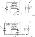
- the energy storage module is connected in parallel with a DC-AC converter.
- the output voltage of the push-pull forward converter which is a DC voltage, can be converted into an AC voltage by the DC-AC converter in order to be able to operate the load unit or the generator unit with AC voltage.
- the figures 1 , 4 , 5 , 6 and 7 schematically show embodiments of hybrid energy storage systems 1, 1′, 1′′, 1′′′ according to the invention based on corresponding circuit arrangements.
- the energy storage systems 1, 1′, 1′′, 1′′′ each have a load unit 2 or a generator unit 2′.
- This can, as in FIGS figures 1 , 4 and 5 shown require direct current or generate direct current or, as in the Figures 6 and 7 shown as an example, be operated with AC voltage or generate AC voltage.
- the energy storage systems 1, 1′, 1′′, 1′′′ also each have an electrochemical energy storage device that is electrically connected to the load unit 2 or the generator unit 2′ 3, through which the load unit 2 is supplied with a battery current I batt in load operation of the respective energy storage system 1, 1', 1" or which is charged in generator operation by the generator unit 2' with a generator current of opposite polarity to the battery current I batt .
- a battery voltage U batt drops across the electrochemical energy store 3 .
- the energy storage systems 1, 1', 1", 1′′′ also each have a capacitive energy storage stack 4.
- the capacitive energy storage stack 4 is in each case constructed from a plurality of series-connected electrical double-layer capacitors 40.
- the capacitive energy storage stack 4 is also referred to here as a supercapacitor stack.
- a storage voltage U stack drops across the capacitive energy storage stack 4.
- the storage voltage U stack typically ranges from 9 to 48 V.
- the capacitive energy storage stack 4 cannot be discharged 100%, typically at least approximately 20% of the maximum energy that can be stored by it always remains in it, so that at least a basic voltage always drops across it.
- the energy storage systems 1, 1', 1", 1′′′ also have an energy storage module 10 with power electronics and a push-pull flux converter 6.
- the push-pull flux converter 6 is, as is also shown schematically in FIGS Figures 4 to 7 shown is a DC-DC converter.
- the push-pull flux converter 6 has a transmission transformer 60 with a primary winding 61 , a secondary winding 62 and an iron core 63 .
- the push-pull forward converter 6 has an LC element with a choke coil 66 and a smoothing capacitor 67 .
- the choke coil 66 is connected to a center tap 64 of the secondary winding 62 .
- the power electronics have a full-bridge circuit 65 composed of switches S1, S2, S3, S4, which is connected to the winding ends of the primary winding 61.
- the output voltage of the push-pull forward converter 6 drops across the smoothing capacitor 67, which is also referred to here as the buffer voltage U C .
- the smoothing capacitor 67 is connected between the positive pole of the load unit 2 or the generator unit 2 ′ and the positive pole of the capacitive energy storage stack 4 .
- the voltage U R dropping across the load unit 2 or the generator unit 2' is thus made up of the sum of the buffer voltage U C and the storage voltage U stack .
- the negative pole of the capacitive energy storage stack 4 is grounded.
- the positive pole of the capacitive energy storage stack 4 is alternately connected to a positive pole at the input of the push-pull forward converter 6 and to a negative pole at the output of the push-pull forward converter 6 .
- the push-pull flux converter 6 has switches S5, S6 connected between the winding ends of the secondary winding 62 and the positive pole of the capacitive energy store.
- the push-pull flux converter 6 - in contrast to the example in the publication DE 10 2015 220 820 A1 described, non-recoverable DC-DC converter, which has only passive diodes on its secondary side - on its secondary side actively controlled switches S5, S6.
- the negative pole of the input of the push-pull flux converter 6 is grounded.
- the positive pole of the output of the push-pull flux converter 6 is connected to the positive pole of the electrochemical energy store 3 .
- Energy storage system 1 shown and thus in principle also in the figures 4 , 6 and 7 Energy storage systems 1', 1", 1′′′ shown work as follows: If the voltage and current control and/or regulation unit 5 recognizes that a current that exceeds a permissible maximum value I battmax by a current I add is required to supply the load unit 2 or is generated by the generator unit 2', the voltage - And current control and / or regulation unit 5 of the push-pull flux converter 6 switched on. In this case, either the switches S1 and S3 of the full-bridge circuit 65 or the switches S2 and S4 of the full-bridge circuit 65 are switched on alternately.
- a first primary current I P1 flows through the primary winding 61 of the push-pull forward converter 6 in a first primary direction.
- a first magnetic field builds up across the primary winding 61 .
- switches S2 and S4 are closed and switches S1 and S3 are open, a second primary current I P2 flows through primary winding 61 of push-pull forward converter 6 in a second primary direction, which is opposite to the first primary direction.
- a second magnetic field builds up across the primary winding 61 .
- switch S5 When the switches S1 and S3 are closed, the switch S5 is closed and the switch S6 is opened synchronously.
- switches S2 and S4 When switches S2 and S4 are closed, switch S6 is closed synchronously and switch S5 is open.
- the switch S5 When the first secondary current I S1 flows, the switch S5 is closed synchronously.
- the switch S6 When the second secondary current I S2 flows, the switch S6 is closed synchronously.
- Switches S5 and S6 are never closed at the same time.
- the secondary current I S which keeps changing its direction, flows into the choke coil 66, in which the current gradually increases and correspondingly gradually decreases.
- a periodic inductor current I L with a triangular course over time flows through the inductor coil 66 .
- the smoothing capacitor 67 is permanently charged and discharged again as a result of the changing current rises in the inductor current I L .
- the smoothing capacitor 67 integrates the inductor current I L flowing through the inductor coil 66, i.e. forms an average value of the inductor coil current I L , so that a DC voltage drops across the smoothing capacitor 67, which is the output voltage of the push-pull forward converter 6 and at the same time a buffer voltage U C of the respective energy storage system 1, 1 ', 1" forms.
- the sum of the dynamic buffer voltage U C dropping across the smoothing capacitor 67 and the storage voltage U stack dropping across the capacitive energy storage stack drops across the load unit 2 or the generator unit 2′.
- the storage voltage U stack always forms a basic voltage for the supply of the load unit 2 or the generator unit 2'.
- the full supply voltage for the load unit 2 does not have to be provided by the push-pull forward converter 6, but only an additional amount of voltage for the supply of the load unit 2 that exceeds a basic voltage.
- the storage voltage U stack provided by the capacitive energy storage stack 4 is used 100% in any case.
- the hybrid energy storage system 1, 1′′′ shown in each case has a step-down converter 7, which in the hybrid energy storage system 1 is connected between the positive pole of the electrochemical energy store 3 and the positive pole of the input of the push-pull flow converter 6 is and is connected in the hybrid energy storage system 1 ′′′ between the positive pole of the output of the push-pull flux converter 6 and the positive pole of the capacitive energy storage stack 4 .
- the respective step-down converter 7 converts a high input voltage U Ebuck into a lower output voltage U Abuck with the aid of current regulation into a regulated output current, which is figure 1 marked I buck .
- the step-down converter 7 is typically constructed as simplified in figure 3 is shown. That is, the step-down converter 7 has an LC element with a step-down converter coil 76 and a step-down converter capacitor 77 across which the output voltage U Abuck of the step-down converter 7 drops, a diode 70 connected in parallel with the step-down converter capacitor 77 and a switch 75 .
- the switch 75 which is a transistor, for example, is then, if by the in figure 1 Voltage and current control and/or regulation unit 5 of the hybrid energy storage system 1 shown as an example, e.g. B. a by the load unit 2 or the generator unit 2 'abruptly generated high feedback current is detected, alternately switched on and off.
- the feedback current flows through the step-down converter coil 76, which blocks the diode 70. Due to the delay effect of the buck converter coil 76, a current with a triangular waveform flows through it. If the switch 75 is switched off, the energy stored in the step-down converter coil 76 is dissipated. Starting from the buck converter capacitor 77, the current now flows through the diode 70.
- the buck converter coil 76 keeps the higher input voltage U Ebuck away from the capacitive energy storage stack 4 .
- the output voltage U Abuck that builds up across the buck converter capacitor 77 when the switch 75 is switched on also drops across the capacitive energy storage stack 4 connected in parallel with the buck converter capacitor 77 and can therefore be used to charge it.
- the step-down converter 7 can, as is shown by the in figure 4 schematically illustrated embodiment of the hybrid energy storage system 1 'is shown, also be omitted.
Abstract
Die vorliegende Erfindung betrifft ein hybrides elektrisches Energiespeichersystem (1) mit einer Lasteinheit (2) oder einer Generatoreinheit, einem elektrochemischen Energiespeicher (3), dessen Pluspol mit der Lasteinheit (2) oder der Generatoreinheit verbunden ist, einem kapazitiven Energiespeicherstapel (4) und einer Spannungs- und Stromsteuerungs- und/oder -regeleinheit (5). Erfindungsgemäß weist das hybride elektrische Energiespeichersystem (1) ein aus dem kapazitiven Energiespeicherstapel (4) und einer Leistungselektronik bestehendes Energiespeichermodul (10) auf, wobei der kapazitive Energiespeicherstapel (4) eine Reihenschaltungsanordnung aus mehreren elektrischen Doppelschichtkondensatoren (40) ist und die Leistungselektronik eine Vollbrückenschaltung (65) und einen Gegentaktflusswandler (6) mit einem Übertragertransformator (60) mit einer mittig geteilten Sekundärwicklung (62) aufweist, wobei eine einzige Primärwicklung (61) des Übertragertransformators (60) im Gegentakt über Schalter (S1,S2,S3,S4) der Vollbrückenschaltung (65) mit dem Pluspol des kapazitiven Energiespeicherstapels (4) und mit Masse verbunden ist, und wobei eine Mittelanzapfung (64) der Sekundärwicklung (62) des Gegentaktflusswandlers (6) über eine Drosselspule (66) des Gegentaktflusswandlers (6) mit dem Pluspol der Lasteinheit (2) oder der Generatoreinheit verbunden ist, der Pluspol des kapazitiven Energiespeicherstapels (4) im Gegentakt mit den Wicklungsenden der Sekundärwicklung (62) des Übertragertransformators (60) verbunden ist und zwischen den Pluspol der Lasteinheit (2) oder der Generatoreinheit und den Pluspol des kapazitiven Energiespeicherstapels (4) ein Glättungskondensator (67) des Gegentaktflusswandlers (6) geschaltet ist.The present invention relates to a hybrid electrical energy storage system (1) with a load unit (2) or a generator unit, an electrochemical energy store (3) whose positive pole is connected to the load unit (2) or the generator unit, a capacitive energy storage stack (4) and a Voltage and current control and/or regulation unit (5). According to the invention, the hybrid electrical energy storage system (1) has an energy storage module (10) consisting of the capacitive energy storage stack (4) and power electronics, the capacitive energy storage stack (4) being a series circuit arrangement made up of a plurality of electric double-layer capacitors (40) and the power electronics being a full bridge circuit ( 65); Full bridge circuit (65) is connected to the positive pole of the capacitive energy storage stack (4) and to ground, and wherein a center tap (64) of the secondary winding (62) of the push-pull forward converter (6) is connected to the positive pole via a choke coil (66) of the push-pull forward converter (6). connected to the load unit (2) or the generator unit, the positive pole of the capacitive energy storage stack (4) is connected in push-pull to the winding ends of the secondary winding (62) of the transmission transformer (60) and a smoothing capacitor (67) of the Push-pull flux converter (6) is connected.
Description
Die vorliegende Erfindung betrifft ein hybrides elektrisches Energiespeichersystem mit einer Lasteinheit oder einer Generatoreinheit, einem elektrochemischen Energiespeicherstapel, dessen Pluspol mit der Lasteinheit oder der Generatoreinheit verbunden ist, einem kapazitiven Energiespeicherstapel und einer Spannungs- und Stromsteuerungs- und/oder -regeleinheit.The present invention relates to a hybrid electrical energy storage system having a load unit or a generator unit, an electrochemical energy storage stack whose positive pole is connected to the load unit or the generator unit, a capacitive energy storage stack and a voltage and current control and/or regulation unit.
Aus dem Stand der Technik sind hybride Energiespeichersysteme bekannt, bei denen verschiedene Speichertechnologien vorteilhaft miteinander kombiniert werden. Durch eine Kombination chemischer, thermischer, mechanischer und/oder elektrischer Energiespeicher können hybride Energiespeichersysteme geschaffen werden, die optimal an die Eigenschaften und Anforderungen des zu speisenden Systems, in welches sie integriert werden sollen, angepasst sind.Hybrid energy storage systems are known from the prior art, in which different storage technologies are advantageously combined with one another. Hybrid energy storage systems can be created by a combination of chemical, thermal, mechanical and/or electrical energy stores, which are optimally adapted to the properties and requirements of the system to be fed, into which they are to be integrated.
Von besonderer Bedeutung sind hierbei hybride, elektrische Energiespeicher, in denen elektrische Energie gespeichert und von welchen elektrische Energie abgegriffen wird. Ein solcher Speicher verfügt in der Regel über einen elektrochemischen Energiespeicher in Form einer Batterie. Diese zeichnet sich durch eine hohe Speicherkapazität aus. Allerdings ist der maximal zulässige Be- und Entladestrom, der bei einer Batterie auch auf längere Zeit zum Einsatz kommen kann, limitiert. Bei Anwendungen, bei denen die Batterieleistung einen zeitlich sehr dynamischen Verlauf zeigt und die Batterie wiederholt schädlichen Leistungsspitzen eines angeschlossenen Generators und/oder Verbrauchers ausgesetzt ist, ist es sinnvoll, den batteriebasierten Energiespeicher durch ein zusätzliches Speichermedium zu unterstützen.Of particular importance here are hybrid electrical energy stores in which electrical energy is stored and from which electrical energy is tapped. Such a store usually has an electrochemical energy store in the form of a battery. This is characterized by a high storage capacity. However, the maximum permissible charging and discharging current that can be used with a battery over a longer period of time is limited. In applications in which the battery performance is very dynamic over time and the battery is repeatedly exposed to harmful power peaks from a connected generator and/or consumer, it makes sense to support the battery-based energy storage system with an additional storage medium.
Beispielsweise lassen sich Leistungsschwankungen durch ein Schwungrad kompensieren. Das Schwungrad bildet einen kinetischen Energiespeicher, der batterieschädliche Lastanteile abfängt und dadurch die Lebensdauer eines elektrochemischen Langzeitspeichers maximiert.For example, power fluctuations can be compensated for by a flywheel. The flywheel forms a kinetic energy store that absorbs battery-damaging load components and thereby maximizes the service life of an electrochemical long-term storage device.
Ein weiterer Ansatz für einen hybriden Energiespeicher besteht in einer Kombination von elektrochemischen Batteriespeichern, wie Hochleistungs- Vanadium-Redox-Flow-Batterien, mit elektrostatischen Doppelschichtkondensatoren, sogenannten Superkondensatoren bzw. Super-Caps. Bei Spannungen über 30 V wird die Nutzung von einfachen Superkondensatoren zusätzlich zu einer Batterie zur Unterstützung dynamischer Belastungen zunehmend ökonomisch ineffizient. Da die Zellspannung von Superkondensatoren bisher bei maximal 3 V liegt, müssen daher bei hohen Spannungen Superkondensatoren gestapelt werden, d. h. in Reihe geschaltet werden, um eine Anwendung technisch zu realisieren.Another approach for a hybrid energy store is a combination of electrochemical battery stores, such as high-performance vanadium redox flow batteries, with electrostatic double-layer capacitors, so-called supercapacitors or supercaps. At voltages above 30V, the use of simple supercapacitors in addition to a battery to support dynamic loads becomes increasingly economically inefficient. Since the cell voltage of supercapacitors has hitherto been a maximum of 3 V, supercapacitors must be stacked at high voltages, i. H. connected in series in order to technically implement an application.
Werden Supercap-Stacks, also in Reihe geschaltete Stapel aus Doppelschichtkondensatoren (EDLC), als zusätzliche Energiespeicher zu Batterien eingesetzt, können mit diesen im Vergleich zu herkömmlichen Kondensatoren sehr hohe Energiemengen gespeichert und auch schnell wieder abgegeben werden. So können aus solchen Supercap-Stacks und Batterien aufgebaute hybride Energiespeichersysteme beispielsweise dazu genutzt werden, Energieverbrauchsspitzen elektrischer Maschinen, wie beispielsweise von Elektrofahrzeugen, schnell zur Verfügung zu stellen oder auch rekuperierte Energie der dann als Generator wirkenden elektrischen Maschine geeignet zu speichern.If supercap stacks, i.e. stacks of double-layer capacitors (EDLC) connected in series, are used as additional energy stores for batteries, they can store very large amounts of energy compared to conventional capacitors and also release them again quickly. Hybrid energy storage systems constructed from such supercap stacks and batteries can be used, for example, to quickly provide energy consumption peaks in electrical machines, such as electric vehicles, or to store recuperated energy from the electrical machine, which then acts as a generator.
Problematisch ist jedoch, dass die in Supercap-Stacks gespeicherte Energie durchschnittlich nur zu 80 % effektiv genutzt werden kann. Zusätzlich steigen mit zunehmender Anzahl von Superkondensatoren auch die Kosten des Supercap-Stacks, was wiederum den Kosten-Nutzen-Faktor des Gesamtgerätes in Frage stellen kann.The problem, however, is that on average only 80% of the energy stored in supercap stacks can be used effectively. In addition, as the number of supercapacitors increases, the cost of the supercap stack also increases, which in turn can call into question the cost-benefit factor of the overall device.
Um die Anzahl der nötigen Superkondensatoren möglichst gering zu halten, wurde bisher mit einer niedrigen Quellspannung bzw. Batteriespannung und einem nachgeschalteten Hochsetzsteller gearbeitet. Hier steigt mit zunehmender Batteriespannung jedoch auch die Anzahl der in Reihe zu schaltenden Superkondensatoren und im Hinblick auf den Hochsetzsteller sinkt ab 70 % Tastverhältnis dessen Wirkungsgrad aufgrund seiner Nichtlinearität. Für die praktische Umsetzung bedeutet dies, dass die Mindestspannung des Supercap-Stacks nicht signifikant größer oder kleiner als die Batteriespannung sein darf. Im ungünstigsten Fall ist in den Superkondensatoren ein zusätzlich hoher Energieinhalt vorhanden, welcher ohnehin schon nicht vollständig genutzt werden kann.In order to keep the number of supercapacitors required as low as possible, a low source voltage or battery voltage and a downstream step-up converter have previously been used. Here, however, the number of supercapacitors to be connected in series also increases with increasing battery voltage, and with regard to the step-up converter, its efficiency drops from a duty cycle of 70% due to its non-linearity. For practical implementation, this means that the minimum voltage of the supercap stack must not be significantly higher or lower than the battery voltage. In the worst case, the supercapacitors have an additional high energy content, which cannot be fully used anyway.
Ein entsprechendes, aus dem Stand der Technik bekanntes Energiespeichersystem weist eine Parallelschaltung aus einem Doppelschichtkondensatorstapel und einem Hochsetzsteller auf, dessen Ausgangsspannung jeweils der kompletten Amplitude der Batteriespannung zur Versorgung der jeweiligen Last entspricht. Bei dieser Schaltung liefert die Batterie zum Teil auch dynamische Anteile zum Laststrom parallel zu dem Doppelschichtkondensatorstapel. Da sich, wie oben bereits erwähnt, Doppelschichtkondensatorstapel aus physikalischen Gründen nie vollständig, sondern typischerweise bis auf ca. 20 % entladen, bleiben diese ca. 20 % stets ungenutzt. Die bekannte Schaltung ist daher hinsichtlich ihrer Topologie ineffizient.A corresponding energy storage system known from the prior art has a parallel circuit made up of a double-layer capacitor stack and a step-up converter whose output voltage corresponds in each case to the full amplitude of the battery voltage for supplying the respective load. In this circuit, the battery also partially supplies dynamic components to the load current in parallel with the double-layer capacitor stack. Since, as already mentioned above, double-layer capacitor stacks are never completely discharged for physical reasons, but typically down to approx. 20%, these remain approx. 20% unused. The known circuit is therefore inefficient in terms of its topology.
Aus der Druckschrift
Darüber hinaus gibt es hybride Energiespeichersysteme, die neben einer Batterie einen Gegentaktflusswandler mit parallel geschaltetem Doppelschichtkondensatorstapel nutzen. Der Doppelschichtkondensatorstapel kann, wie bereits erläutert, nur bis zu ca. 20 % entladen werden. Es muss aber trotzdem die volle Ausgangsspannung für die Last bereit gestellt werden, da sonst kein Strom durch die Last mehr fließt. Diese volle Ausgangsspannung liefert hier der Gegentaktflusswandler. Bei Schaltungsvarianten mit Gegentaktflusswandler ist deren Wandler-Topologie energieeffizienter als bei Nutzung eines Hochsetzstellers. Allerdings gilt auch hier, dass mit steigender zu unterstützender Batteriespannung mehr Superkondensatoren in Reihe geschaltet werden müssen.There are also hybrid energy storage systems that use a push-pull forward converter with a double-layer capacitor stack connected in parallel in addition to a battery. As already explained, the double-layer capacitor stack can only be discharged up to approx. 20%. However, the full output voltage must still be provided for the load, otherwise no current will flow through the load. The push-pull forward converter supplies this full output voltage. In the case of circuit variants with push-pull forward converters, their converter topology is more energy-efficient than when using a step-up converter. However, it also applies here that as the battery voltage to be supported increases, more supercapacitors have to be connected in series.
Der Gegentaktflusswandler wird bei der bekannten Schaltung technisch sinnlos, je niedriger die Spannung über dem Doppelschichtkondensator ist. Wenn der Doppelschichtkondensatorstapel unter 20 % entladen ist, fallen solch hohe Spannungen über den Bauelementen des Gegentaktflusswandlers und des Doppelschichtkondensatorstapels ab, d. h. die ohmschen Anteile der kapazitiven Energiespeicherschaltung werden so hoch, dass es nicht effizient ist, weitere Energie aus dem Doppelschichtkondensatorstapel zu entnehmen. Das heißt, wenn der Doppelschichtkondensatorstapel unter 20 % entladen ist, verliert er seine Funktionalität. Die entsprechende Regelschaltung stellt daher in diesem Fall typischerweise die Stromversorgung der Last nur durch die Batterie her.In the known circuit, the push-pull forward converter becomes technically meaningless the lower the voltage across the double-layer capacitor. When the double layer capacitor stack is discharged below 20%, such high voltages drop across the push-pull forward converter and double layer capacitor stack components, i. H. the resistive components of the capacitive energy storage circuit become so high that it is not efficient to extract more energy from the double layer capacitor stack. That is, when the double layer capacitor stack is discharged below 20%, it loses its functionality. In this case, therefore, the corresponding control circuit typically provides the power supply to the load only from the battery.
Es ist daher die Aufgabe der vorliegenden Erfindung, ein Energiespeichersystem zur Verfügung zu stellen, welches einen Doppelschichtkondensatorstapel und einen elektrochemischen Energiespeicher aufweist und bei dem darüber hinaus die gesamte in dem Doppelschichtkondensatorstapel gespeicherte Energie effektiv nutzbar ist.It is therefore the object of the present invention to provide an energy storage system which has a double-layer capacitor stack and an electrochemical energy store and in which the entire energy stored in the double-layer capacitor stack can also be used effectively.
Diese Aufgabe wird durch ein hybrides elektrisches Energiespeichersystem mit einer Lasteinheit oder einer Generatoreinheit, einem elektrochemischen Energiespeicher, dessen Pluspol mit der Lasteinheit oder der Generatoreinheit verbunden ist, einem kapazitiven Energiespeicherstapel und einer Spannungs- und Stromsteuerungs- und/oder -regeleinheit gelöst, wobei das hybride elektrische Energiespeichersystem ein aus dem kapazitiven Energiespeicherstapel und einer Leistungselektronik bestehendes Energiespeichermodul aufweist, wobei der kapazitive Energiespeicherstapel eine Reihenschaltungsanordnung aus mehreren elektrischen Doppelschichtkondensatoren ist und die Leistungselektronik eine Vollbrückenschaltung und einen Gegentaktflusswandler mit einem Übertragertransformator mit einer mittig geteilten Sekundärwicklung aufweist, wobei eine einzige Primärwicklung des Übertragertransformators im Gegentakt über Schalter der Vollbrückenschaltung mit dem Pluspol des kapazitiven Energiespeicherstapels bzw. mit Masse verbunden ist, und wobei eine Mittelanzapfung der Sekundärwicklung des Gegentaktflusswandlers über eine Drosselspule des Gegentaktflusswandlers mit dem Pluspol der Lasteinheit oder der Generatoreinheit verbunden ist, der Pluspol des kapazitiven Energiespeicherstapels im Gegentakt mit den Wicklungsenden der Sekundärwicklung des Übertragertransformators verbunden ist bzw. zwischen den Pluspol der Lasteinheit oder der Generatoreinheit und den Pluspol des kapazitiven Energiespeicherstapels ein Glättungskondensator des Gegentaktflusswandlers geschaltet ist.This object is achieved by a hybrid electrical energy storage system with a load unit or a generator unit, an electrochemical energy store whose positive pole is connected to the load unit or the generator unit, a capacitive energy storage stack and a voltage and current control and/or regulation unit, the hybrid Electrical energy storage system has an energy storage module consisting of the capacitive energy storage stack and power electronics, the capacitive energy storage stack being a series circuit arrangement made up of a plurality of electric double-layer capacitors and the power electronics having a full-bridge circuit and a push-pull forward converter with a transmission transformer with a secondary winding divided in the middle, with a single primary winding of the transmission transformer in the Push-pull across switches of the full bridge circuit with the positive pole of the capacitive energy storage stack or is connected to ground, and wherein a center tap of the secondary winding of the push-pull flux converter is connected to the positive pole of the load unit or the generator unit via a choke coil of the push-pull flux converter, the positive pole of the capacitive energy storage stack is connected in push-pull to the winding ends of the secondary winding of the transmission transformer or between the positive pole of the load unit or a smoothing capacitor of the push-pull forward converter is connected to the generator unit and the positive pole of the capacitive energy storage stack.
Das erfindungsgemäße hybride Energiespeichersystem arbeitet wie folgt:
Durch den elektrochemischen Energiespeicher, also typischerweise eine Batterie oder ein Akkumulator, wird die Lasteinheit im Lastbetrieb mit einem Batteriestrom versorgt. Das heißt, bei geschlossenem Stromkreis fließt der Batteriestrom ausgehend von dem elektrochemischen Energiespeicher im Lastbetrieb zu der Lasteinheit. Im Generatorbetrieb wird durch die Generatoreinheit der Batteriestrom, mit dem der elektrochemische Energiespeicher geladen wird, erzeugt.The hybrid energy storage system according to the invention works as follows:
The load unit is supplied with battery current during load operation by the electrochemical energy store, that is to say typically a battery or an accumulator. This means that when the circuit is closed, the battery current flows from the electrochemical energy store to the load unit in load operation. In generator mode, the battery current, with which the electrochemical energy store is charged, is generated by the generator unit.
Kommt es zu Stromspitzen, das heißt, hat die Lasteinheit in einem Überlastbetrieb einen erhöhten Stromverbrauch bzw. wird durch die Generatoreinheit im Generatorbetrieb ein höherer Strom erzeugt, als zur Ladung des elektrochemischen Energiespeichers benötigt wird bzw. als dieser insbesondere im Hinblick auf dessen Lebenszeit verträgt, wird ein den maximal durch den elektrochemischen Energiespeicher zur Verfügung gestellten bzw. maximal für den elektrochemischen Energiespeicher zulässigen, maximalen Batteriestrom übersteigender Zusatzstrom durch den aus der Reihenschaltungsanordnung aus den mehreren Doppelschichtkondensatoren ausgebildeten kapazitiven Energiespeicher, der im Folgenden der Einfachheit halber als Superkondensatorstapel bezeichnet ist, bereitgestellt bzw. für dessen Aufladung verwendet. Bei der vorliegenden Erfindung kommt, wenn der Batteriestrom zulässige Werte überschreitet, eine Schaltungsanordnung aus dem Superkondensatorstapel und dem den Gegentaktflusswandler beinhaltenden Energiespeichermodul zum Einsatz.If current peaks occur, i.e. if the load unit has an increased power consumption in overload mode or if the generator unit in generator mode generates a higher current than is required to charge the electrochemical energy store or than it can tolerate, especially with regard to its service life, an additional current exceeding the maximum provided by the electrochemical energy store or maximum permissible for the electrochemical energy store, maximum battery current is provided or .used for charging it. In the present invention, when the battery current exceeds allowable values, a circuit arrangement of the supercapacitor stack and the energy storage module containing the push-pull forward converter is used.
Die Spannungs- und Stromsteuerungs- und/oder -regeleinheit überwacht die Ströme und Spannungen innerhalb des erfindungsgemäßen hybriden Energiespeichersystems. Werden durch die Spannungs- und Stromsteuerungs- und/oder -regeleinheit den maximalen Batteriestrom übersteigende Stromspitzen erkannt, werden durch die Spannungs- und Stromsteuerungs- und/oder -regeleinheit die Schaltungskomponenten des erfindungsgemäßen hybriden Energiespeichersystems zur Vermeidung einer Schädigung des elektrochemischen Energiespeichers derart gesteuert oder geregelt, dass nur der maximale Batteriestrom zu dem elektrochemischen Energiespeicher fließt und der überschüssige Zusatzstrom in Richtung des Superkondensatorstapels fließt.The voltage and current control and/or regulation unit monitors the currents and voltages within the hybrid energy storage system according to the invention. If current peaks exceeding the maximum battery current are detected by the voltage and current control and/or regulation unit, the circuit components of the hybrid energy storage system according to the invention are controlled or regulated by the voltage and current control and/or regulation unit in order to avoid damage to the electrochemical energy store that only the maximum Battery current flows to the electrochemical energy storage and the excess boost current flows toward the supercapacitor stack.
Der Superkondensatorstapel ist aus mehreren in Reihe geschalteten Doppelschichtkondensatoren ausgebildet. Doppelschichtkondensatoren bzw. sogenannte Superkondensatoren weisen im Vergleich zu Akkumulatoren bei gleichem Gewicht nur etwa 10 % von deren Energiedichte auf. Allerdings ist die Leistungsdichte von Doppelschichtkondensatoren 10 bis 100 mal so groß wie die von Akkumulatoren. Der Superkondensatorstapel ist zwar ohne Weiteres vollständig aufladbar, aber physikalisch bedingt nicht zu 100 %, sondern typischerweise nur bis zu ca. 80 % entladbar.The supercapacitor stack is formed from a plurality of double layer capacitors connected in series. Double-layer capacitors or so-called supercapacitors only have about 10% of the energy density of accumulators with the same weight. However, the power density of double-layer capacitors is 10 to 100 times that of accumulators. Although the supercapacitor stack can be fully charged without further ado, it cannot be 100% discharged for physical reasons, but can typically only be discharged up to about 80%.
Bei dem erfindungsgemäßen hybriden Energiespeichersystem fließt der die Stromspitzen beinhaltende Zusatzstrom ausgehend von der Generatoreinheit bzw. zu der Lasteinheit zunächst durch eine Parallelschaltung aus einerseits dem Glättungskondensator und andererseits dem Übertragertransformator und der Drosselspule, bevor er zu dem Superkondensatorstapel fließt. Es wird also immer zuerst der Glättungskondensator im Lastbetrieb entladen bzw. im Generatorbetrieb aufgeladen, bevor der Superkondensatorstapel im Lastbetrieb entladen bzw. im Generatorbetrieb aufgeladen wird. Da der Glättungskondensator ein einfacher Kondensator ist, ist dessen Entladung bzw. Aufladung schnell und vollständig möglich.In the hybrid energy storage system according to the invention, the additional current containing the current peaks flows from the generator unit or to the load unit first through a parallel circuit consisting of the smoothing capacitor on the one hand and the transmission transformer and the inductor on the other before it flows to the supercapacitor stack. The smoothing capacitor is therefore always first discharged in load operation or charged in generator operation before the supercapacitor stack is discharged in load operation or charged in generator operation. Since the smoothing capacitor is a simple capacitor, it can be discharged or charged quickly and completely.
Der Gegentaktflusswandler ist ein Gegentaktflusswandler in Vollbrückensteuerung. Der Gegentaktflusswandler wird durch entsprechende Schaltung der Schalter der Vollbrückenschaltung mittels der Spannungs- und Stromsteuerungs- und/oder -regeleinheit im Gegentakt betrieben. Die Schalter der Vollbrückenschaltung sind beispielsweise MOS-FETs.The push-pull flux converter is a push-pull flux converter in full-bridge control. The push-pull forward converter is operated in push-pull mode by appropriate switching of the switches of the full bridge circuit by means of the voltage and current control and/or regulation unit. The switches of the full bridge circuit are MOSFETs, for example.
Der Gegentaktflusswandler ist ein bidirektionaler DC/DC-Wandler, d. h., er wandelt eine Eingangsgleichspannung, die vorliegend über dem elektrochemischen Energiespeicher anliegt, in eine Ausgangsgleichspannung, die vorliegend über dem Glättungskondensator des Gegentaktflusswandlers anliegt, um und umgekehrt.The push-pull forward converter is a bidirectional DC/DC converter, i. That is, it converts an input DC voltage, which is present across the electrochemical energy store, into an output DC voltage, which is present across the smoothing capacitor of the push-pull forward converter, and vice versa.
Der Übertragertransformator schafft eine galvanische Trennung zwischen einem Primärkreis und einem Sekundärkreis.The transmission transformer provides galvanic isolation between a primary circuit and a secondary circuit.
Bei einer ersten Schalterstellung der Schalter der Vollbrückenschaltung wird die Primärwicklung des Übertragertransformators des Gegentaktflusswandlers in einer ersten Primärrichtung von Primärstrom durchflossen, wodurch sich über der Primärwicklung ein erstes Magnetfeld aufbaut. Dieses erste Magnetfeld wirkt mittels des Eisenkerns des Übertragertransformators auf die Sekundärwicklung, in der ein in einer ersten Sekundärrichtung fließender Sekundärstrom induziert wird. Bei einer zweiten Schalterstellung der Schalter der Vollbrückenschaltung wird die Primärwicklung des Übertragertransformators des Gegentaktflusswandlers in einer zweiten Primärrichtung von Primärstrom durchflossen, wodurch sich über der Primärwicklung ein zweites Magnetfeld aufbaut. Dieses zweite Magnetfeld wirkt mittels des Eisenkerns des Übertragertransformators auf die Sekundärwicklung, in der ein in einer zweiten Sekundärrichtung fließender Sekundärstrom induziert wird.In a first switch position of the switch of the full bridge circuit, the primary winding of the transmission transformer of the push-pull flux converter is traversed in a first primary direction by primary current, as a result of which a first magnetic field builds up over the primary winding. By means of the iron core of the transformer, this first magnetic field acts on the secondary winding, in which a secondary current flowing in a first secondary direction is induced. In a second switch position of the switches of the full-bridge circuit, the primary winding of the transmission transformer of the push-pull forward converter is traversed in a second primary direction by primary current, as a result of which a second magnetic field builds up over the primary winding. By means of the iron core of the transmission transformer, this second magnetic field acts on the secondary winding, in which a secondary current flowing in a second secondary direction is induced.
Durch das kontinuierliche Wechseln der Schalterstellung der Schalter der Vollbrückenschaltung wird an der Sekundärwicklung eine periodisch wechselnde Rechteckspannung bzw. ein periodisch seine Richtung ändernder Strom erzeugt.By continuously changing the switch position of the switches of the full-bridge circuit, a periodically changing square-wave voltage or a periodically changing current is generated at the secondary winding.
Dieser Strom wird mittels des mit der Sekundärwicklung verbundenen und aus der Drosselspule und dem Glättungskondensator zusammengesetzten LC-Gliedes geglättet, sodass am Ausgang des Gegentaktflusswandlers, d. h. über dem Glättungskondensator, eine Gleichspannung zur Verfügung steht. Das geschieht folgendermaßen:
Das LC-Glied weist in der vorliegenden Erfindung die zwischen die Mittelanzapfung der Sekundärwicklung und den Pluspol der Lasteinheit oder der Generatoreinheit geschaltete Drosselspule und den zwischen den Pluspol des kapazitiven Energiespeicherstapels und den Pluspol der Last- oder Generatoreinheit geschalteten Glättungskondensator auf. Wird an der Sekundärwicklung ein in die erste oder zweite Sekundärrichtung fließender Sekundärstrom induziert, steigt der Spulenstrom, der durch die Drosselspule fließt, allmählich an. Umgekehrt sinkt der Spulenstrom durch die Drosselspule, wenn an der Sekundärwicklung keine Sekundärspannung von der Primärwicklung her induziert wird. Im Ergebnis fließt durch die Drosselspule ein periodischer Strom mit zeitlich dreieckförmigem Verlauf.This current is smoothed by means of the LC element connected to the secondary winding and composed of the choke coil and the smoothing capacitor, so that a DC voltage is available at the output of the push-pull forward converter, ie across the smoothing capacitor. This happens as follows:
The LC element in the present invention has the choke coil connected between the center tap of the secondary winding and the positive pole of the load unit or generator unit and the smoothing capacitor connected between the positive pole of the capacitive energy storage stack and the positive pole of the load unit or generator unit. When a secondary current flowing in the first or second secondary direction is induced in the secondary winding, the coil current flowing through the choke coil gradually increases. Conversely, if no secondary voltage is induced on the secondary winding from the primary winding, the coil current through the choke coil will decrease. As a result, a periodic current with a triangular course over time flows through the choke coil.
Durch die sich ändernde Stromrichtung wird der Glättungskondensator dauerhaft aufgeladen und wieder entladen. Der Glättungskondensator integriert den durch die Drosselspule fließenden Spulenstrom, bildet also einen Mittelwert des Drosselspulenstroms, sodass über dem Glättungskondensator eine Gleichspannung abfällt, die die Ausgangsspannung des Gegentaktflusswandlers bildet. Es findet also eine Stromspitzenglättung statt.Due to the changing direction of the current, the smoothing capacitor is permanently charged and then discharged again. The smoothing capacitor integrates the coil current flowing through the choke coil, thus forming an average value of the choke coil current, so that a DC voltage drops across the smoothing capacitor, which forms the output voltage of the push-pull forward converter. Current peak smoothing therefore takes place.
Bei der vorliegenden Erfindung fällt über der Lasteinheit oder der Generatoreinheit jedoch nicht nur die Ausgangsspannung des Gegentaktflusswandlers, sondern die Summe aus der Ausgangsspannung des Gegentaktflusswandlers und der über dem als Superkondensatorstapel ausgebildeten kapazitiven Energiespeicherstapel abfallenden Speicherspannung ab. Die Spannung über der Lasteinheit oder der Generatoreinheit setzt sich also aus der eine gespeicherte Energie darstellenden Grundspannung, die über dem kapazitiven Energiespeicher abfällt, und einer dynamischen Pufferspannung, die über dem Glättungskondensator abfällt, zusammen.In the present invention, however, not only the output voltage of the push-pull forward converter drops across the load unit or the generator unit, but rather the sum of the output voltage of the push-pull forward converter and the storage voltage drop across the capacitive energy storage stack designed as a supercapacitor stack. The voltage across the load unit or the generator unit is therefore composed of the basic voltage representing stored energy, which drops across the capacitive energy store, and a dynamic buffer voltage, which drops across the smoothing capacitor.
Die in dem kapazitiven Energiespeicherstapel gespeicherte Energie liefert also stets eine Grundspannung zusätzlich zu der Ausgangsspannung des Gegentaktflusswandlers für die Lasteinheit oder die Generatoreinheit. Es muss daher bei der vorliegenden Erfindung im Lastbetrieb lediglich ein Teil des von der Last- oder Generatoreinheit benötigten Energiebedarfs von dem Gegentaktflusswandler zur Verfügung gestellt werden bzw. im Generatorbetrieb lediglich ein Teil der von der Last- oder Generatoreinheit generierten Energie von dem Glättungskondensator des Gegentaktflusswandlers aufgenommen werden. Die Auslegung des Gegentaktflusswandlers kann daher sehr effizient gestaltet werden.The energy stored in the capacitive energy storage stack thus always supplies a basic voltage in addition to the output voltage of the push-pull forward converter for the load unit or the generator unit. In the present invention, therefore, only part of the energy required by the load or generator unit has to be made available by the push-pull flux converter in load operation or, in generator operation, only part of the energy generated by the load or generator unit has to be absorbed by the smoothing capacitor of the push-pull flux converter will. The design of the push-pull flux converter can therefore be designed very efficiently.
Auch wenn sich der Superkondensatorstapel in der Praxis nie zu 100 % entlädt, liegt bei der vorliegenden Erfindung der ökonomische Nutzen dieses Bauteils bei 100 %. Das heißt, die Restenergie des Superkondensatorstapels kann selbst bei weiter Entladung des Superkondensatorstapels zusätzlich zu der durch den Gegentaktflusswandler erzeugten Ausgangsspannung genutzt werden.Even if the supercapacitor stack never discharges 100% in practice, in the present invention the economic benefit of this device is 100%. That is, the residual energy of the supercapacitor stack can be used in addition to the output voltage generated by the push-pull forward converter even if the supercapacitor stack is further discharged.
In Folge der speziellen Schaltungsanordnung können bei der vorliegenden Erfindung der elektrochemische Energiespeicher nicht nur durch gezielte Spitzenglättung in seinem "Wohlfühlbereich" betrieben, sondern auch die Stromanstiege gedämpft werden. Daraus resultiert eine signifikant höhere Lebensdauer des elektrochemischen Energiespeichers bei einer kostenoptimalen Ausnutzung der unterstützenden Doppelschichtkondensatoren.As a result of the special circuit arrangement, in the present invention, the electrochemical energy store can not only be achieved by targeted peak smoothing in its "Feel good range" operated, but also the current increases are dampened. This results in a significantly longer service life of the electrochemical energy store with cost-optimal utilization of the supporting double-layer capacitors.
Um eine geeignete Zusatz-Energieversorgung der Lasteinheit oder eine geeignete Zusatz-Speichermöglichkeit für die Generatoreinheit durch den Superkondensatorstapel zur Verfügung stellen zu können, sollte dieser in der Praxis mindestens zur Hälfte oder gar mindestens zu Dreiviertel seiner Gesamtkapazität aufgeladen sein. Insbesondere dann, wenn Rückspeisungen durch die Lasteinheit oder die Generatoreinheit erwartet werden können, sollte der Superkondensatorstapel jedenfalls zu Beginn seines Einsatzes nicht zu 100 % aufgeladen sein.In order to be able to provide a suitable additional energy supply for the load unit or a suitable additional storage option for the generator unit through the supercapacitor stack, in practice it should be charged to at least half or even at least three-quarters of its total capacity. In any case, the supercapacitor stack should not be 100% charged at the beginning of its use, especially if feedback from the load unit or the generator unit can be expected.
In einer vorteilhaften Ausführungsform des erfindungsgemäßen hybriden elektrischen Energiespeichersystems weist dieses einen zwischen den Pluspol des elektrochemischen Energiespeichers und den Pluspol des kapazitiven Energiespeicherstapels geschalteten Tiefsetzsteller auf.In an advantageous embodiment of the hybrid electrical energy storage system according to the invention, this has a step-down converter connected between the positive pole of the electrochemical energy store and the positive pole of the capacitive energy storage stack.
Durch den optional bei dem erfindungsgemäßen hybriden elektrischen Energiespeichersystem einsetzbaren, in Reihe zwischen die Lasteinheit oder die Generatoreinheit und den Superkondensatorstapel geschalteten Bypass-Tiefsetzsteller wird die Dynamik der Spannungs- und Stromsteuerungs- und/oder -regeleinheit des Energiespeichersystems insbesondere bei Rückspeisung von Energie aus der Lasteinheit oder der Generatoreinheit in den Superkondensatorstapel erhöht.The dynamics of the voltage and current control and/or regulation unit of the energy storage system, in particular when energy is fed back from the load unit, are increased by the bypass buck converter that can optionally be used in the hybrid electrical energy storage system according to the invention and is connected in series between the load unit or the generator unit and the supercapacitor stack or the generator unit into the supercapacitor stack.
Die oben beschriebene Rückspeisung könnte beispielsweise vorgenommen werden, wenn die Lasteinheit ein Fahrzeug ist, an dem eine Vollbremsung durchgeführt wird, wo also in sehr kurzer Zeit eine hohe Energie erzeugt wird, die rückgespeist werden kann, wodurch die eigentliche Lasteinheit als Generatoreinheit wirkt. Bei einer solchen Vollbremsung kann die Spannungs- und Stromsteuerungs- und/oder -regeleinheit des Energiespeichersystems durch Umschaltung von einer positiven Stellgröße auf eine negative Stellgröße den Gegentaktflusswandler nicht sofort von Treiben auf Senke umschalten. Vielmehr braucht es hierfür eine endliche Zeit, wobei das erforderliche Zeitintervall lastabhängig ist.The feedback described above could be carried out, for example, if the load unit is a vehicle on which emergency braking is carried out, where a high level of energy is generated in a very short time, which can be fed back, whereby the actual load unit acts as a generator unit. In the event of such emergency braking, the voltage and current control and/or regulation unit of the energy storage system cannot immediately switch the push-pull flux converter from driving to sinking by switching from a positive manipulated variable to a negative manipulated variable. Rather, it takes a finite amount of time for this, with the time interval required being load-dependent.
Dagegen kann der Tiefsetzsteller sofort beim Bremsvorgang einsetzen. Das heißt, in der Zeit, in der der Gegentaktflusswandler noch nicht bzw. noch nicht vollständig von Treiben in Senke umgeschaltet ist, fließt der von der als Generatoreinheit wirkenden Lasteinheit rückgespeiste Strom in den Tiefsetzsteller, durch den wiederum der Superkondensatorstapel vorgeladen wird. Dabei wird durch den Tiefsetzsteller der Strom herabgesetzt, der in den eine niederohmige Last darstellenden Superkondensatorstapel fließt. Dadurch wird der Zeitraum, in dem der Gegentaktflusswandler von Treiben auf Senke umschalten muss, überbrückt.In contrast, the step-down converter can start immediately during the braking process. This means that during the period in which the push-pull forward converter has not yet or not yet fully switched from driving to sinking, the current fed back by the load unit acting as a generator unit flows into the step-down converter, which in turn precharges the supercapacitor stack. In this case, the current flowing into the supercapacitor stack, which represents a low-impedance load, is reduced by the step-down converter. This bridges the period in which the push-pull flux converter has to switch from driving to sinking.
Der Tiefsetzsteller kommt vorzugsweise nur dann zum Einsatz, wenn durch die Lasteinheit keine Energie gefordert wird bzw. wenn durch die als Generatoreinheit wirkende Lasteinheit, wie bei abrupten Bremsvorgängen, Energie erzeugt wird. Im Normallastbetrieb fließt typischerweise kein Strom durch den Tiefsetzsteller.The step-down converter is preferably used only when no energy is required by the load unit or when energy is generated by the load unit acting as a generator unit, as in the case of abrupt braking processes. In normal load operation, typically no current flows through the step-down converter.
Indem bei dem erfindungsgemäßen hybriden Energiespeichersystem der Tiefsetzsteller zum Einsatz kommt, kann das Energiespeichersystem effizient von Speisebetrieb auf Rückspeisebetrieb und umgekehrt umgestellt werden, wobei es hohen stromdynamischen Anforderungen standhält.Because the step-down converter is used in the hybrid energy storage system according to the invention, the energy storage system can be switched efficiently from feed operation to feedback operation and vice versa, with it withstanding high dynamic current requirements.
In manchen Anwendungen der Erfindung ist es von Vorteil, wenn das Energiespeichermodul parallel zu einem DC-AC-Wandler geschaltet ist. Durch den DC-AC-Wandler kann die Ausgangsspannung des Gegentaktflusswandlers, die eine Gleichspannung ist, in eine Wechselspannung umgewandelt werden, um die Lasteinheit oder die Generatoreinheit mit Wechselspannung betreiben zu können.In some applications of the invention it is advantageous if the energy storage module is connected in parallel with a DC-AC converter. The output voltage of the push-pull forward converter, which is a DC voltage, can be converted into an AC voltage by the DC-AC converter in order to be able to operate the load unit or the generator unit with AC voltage.
Ausführungsformen der vorliegenden Erfindung, deren Aufbau Funktion und Vorteile werden im Folgenden anhand von Figuren näher erläutert, wobei
Figur 1- schematisch eine Ausführungsform eines erfindungsgemäßen hybriden Energiespeichersystems mit einem Tiefsetzsteller anhand einer Schaltungsanordnung zeigt;
Figur 2- einen Gegentaktflusswandler des erfindungsgemäßen hybriden Energie-speichersystems als Schaltungsanordnung und als entsprechendes Schaltzeichen zeigt;
Figur 3- schematisch einen Schaltungsaufbau des in der Ausführungsform der Figuren 1 und 5 verwendeten Tiefsetzstellers zeigt;
Figur 4- schematisch eine Ausführungsform eines erfindungsgemäßen hybriden Energiespeichersystems anhand einer vereinfachten Schaltungsdarstellung zeigt;
Figur 5- schematisch das erfindungsgemäße hybride Energiespeichersystem aus
Figur 1 in vereinfachter Schaltungsdarstellung zeigt; Figur 6- schematisch eine Ausführungsform eines erfindungsgemäßen hybriden Energiespeichersystems mit DC-AC-Wandler anhand einer vereinfachten Schaltungsdarstellung zeigt; und
Figur 7- schematisch eine Ausführungsform eines erfindungsgemäßen hybriden Energiespeichersystems mit Tiefsetzsteller und DC-AC-Wandler anhand einer vereinfachten Schaltungsdarstellung zeigt.
- figure 1
- schematically shows an embodiment of a hybrid energy storage system according to the invention with a step-down converter using a circuit arrangement;
- figure 2
- shows a push-pull flux converter of the hybrid energy storage system according to the invention as a circuit arrangement and as a corresponding circuit symbol;
- figure 3
- Fig. 12 shows schematically a circuit structure of the step-down converter used in the embodiment of Figs. 1 and 5;
- figure 4
- schematically shows an embodiment of a hybrid energy storage system according to the invention based on a simplified circuit diagram;
- figure 5
- schematically the hybrid energy storage system according to the invention
figure 1 shows in a simplified circuit diagram; - figure 6
- schematically shows an embodiment of a hybrid energy storage system according to the invention with a DC-AC converter based on a simplified circuit diagram; and
- figure 7
- schematically shows an embodiment of a hybrid energy storage system according to the invention with step-down converter and DC-AC converter based on a simplified circuit diagram.
Die
Die Energiespeichersysteme 1, 1', 1", 1‴ weisen jeweils eine Lasteinheit 2 oder eine Generatoreinheit 2' auf. Diese kann, wie in den
Die Energiespeichersysteme 1, 1', 1", 1‴ weisen ferner jeweils einen mit der Lasteinheit 2 oder der Generatoreinheit 2' elektrisch verbundenen elektrochemischen Energiespeieher 3 auf, durch den die Lasteinheit 2 im Lastbetrieb des jeweiligen Energiespeichersystems 1, 1', 1" mit einem Batteriestrom Ibatt versorgt wird bzw. der im Generatorbetrieb durch die Generatoreinheit 2' mit einem zu dem Batteriestrom Ibatt entgegengesetzt gepolten Generatorstrom geladen wird. Über dem elektrochemischen Energiespeicher 3 fällt eine Batteriespannung Ubatt ab.The
Die Energiespeichersysteme 1, 1', 1", 1‴ weisen zudem jeweils einen kapazitiven Energiespeicherstapel 4 auf. Der kapazitive Energiespeicherstapel 4 ist jeweils aus einer Mehrzahl von in Reihe geschalteten elektrischen Doppelschichtkondensatoren 40 aufgebaut. Der kapazitive Energiespeicherstapel 4 wird vorliegend auch als Superkondensatorstapel bezeichnet. Über dem kapazitiven Energiespeicherstapel 4 fällt eine Speicherspannung Ustack ab. Die Speicherspannung Ustack bewegt sich typischerweise in einem Bereich von 9 bis 48 V.The
Der kapazitive Energiespeicherstapel 4 ist aus physikalischen Gründen nicht zu 100 % entladbar, typischerweise verbleibt in ihm immer mindestens ca. 20 % der maximal von ihm speicherbaren Energie, sodass immer zumindest eine Grundspannung über ihm abfällt.For physical reasons, the capacitive
Die Energiespeichersysteme 1, 1', 1", 1‴ weisen außerdem ein Energiespeichermodul 10 mit einer Leistungselektronik und einem Gegentaktflusswandler 6 auf. Der Gegentaktflusswandler 6 ist, wie es auch schematisch in den
Im Gegensatz zu der Druckschrift
Der Gegentaktflusswandler 6 weist einen Übertragertransformator 60 mit einer Primärwicklung 61, einer Sekundärwicklung 62 und einem Eisenkern 63 auf. Darüber hinaus weist der Gegentaktflusswandler 6 ein LC-Glied mit einer Drosselspule 66 und einem Glättungskondensator 67 auf.The push-
Die Drosselspule 66 ist mit einer Mittelanzapfung 64 der Sekundärwicklung 62 verbunden.The
Die Leistungselektronik weist eine aus Schaltern S1, S2, S3, S4 zusammengesetzte Vollbrückenschaltung 65 auf, die mit den Wicklungsenden der Primärwicklung 61 verbunden ist.The power electronics have a full-
Über dem Glättungskondensator 67 fällt die Ausgangsspannung des Gegentaktflusswandlers 6 ab, die vorliegend auch als Pufferspannung UC bezeichnet wird.The output voltage of the push-
Der Glättungskondensator 67 ist zwischen den Pluspol der Lasteinheit 2 oder der Generatoreinheit 2' und den Pluspol des kapazitiven Energiespeicherstapels 4 geschaltet. Die über der Lasteinheit 2 oder der Generatoreinheit 2' abfallende Spannung UR setzt sich somit aus der Summe aus der Pufferspannung UC und der Speicherspannung Ustack zusammen.The smoothing
Der Minuspol des kapazitiven Energiespeicherstapels 4 liegt auf Masse.The negative pole of the capacitive
Der Pluspol des kapazitiven Energiespeicherstapels 4 ist abwechselnd mit einem Pluspol am Eingang des Gegentaktflusswandlers 6 bzw. mit einem Minuspol am Ausgang des Gegentaktflusswandlers 6 verbunden. Der Gegentaktflusswandler 6 weist hierfür zwischen die Wicklungsenden der Sekundärwicklung 62 und den Pluspol des kapazitiven Energiespeichers geschaltete Schalter S5, S6 auf. Somit weist also der Gegentaktflusswandler 6 - im Gegensatz zu dem beispielsweise in der Druckschrift
Der Minuspol des Eingangs des Gegentaktflusswandlers 6 liegt auf Masse.The negative pole of the input of the push-
Der Pluspol des Ausgangs des Gegentaktflusswandlers 6 ist mit dem Pluspol des elektrochemischen Energiespeichers 3 verbunden.The positive pole of the output of the push-
Das in den
Wird durch die Spannungs- und Stromsteuerungs- und/oder -regeleinheit 5 erkannt, dass ein einen zulässigen Maximalwert Ibattmax um einen Strom Iadd übersteigender Strom zur Versorgung der Lasteinheit 2 nötig ist oder von der Generatoreinheit 2' generiert wird, wird durch die Spannungs- und Stromsteuerungs- und/oder -regeleinheit 5 der Gegentaktflusswandler 6 eingeschaltet. Dabei werden wechselweise entweder die Schalter S1 und S3 der Vollbrückenschaltung 65 oder die Schalter S2 und S4 der Vollbrückenschaltung 65 eingeschaltet.That in the
If the voltage and current control and/or
Dadurch kann über den kapazitiven Energiespeicherstapel 4 darin gespeicherte Energie dem Gegentaktflusswandler 6 im Gegentakt zugeführt werden.As a result, energy stored in the capacitive
Sind die Schalter S1 und S3 geschlossen und die Schalter S2 und S4 geöffnet, fließt durch die Primärwicklung 61 des Gegentaktflusswandlers 6 ein erster Primärstrom IP1 in einer ersten Primärrichtung. Es baut sich ein erstes Magnetfeld über der Primärwicklung 61 auf. Dieses induziert mittels des Eisenkerns 63 des Übertragertransformators 60 in der Sekundärwicklung 62 einen ersten Sekundärstrom IS1, der in eine erste Sekundärrichtung fließt. Wenn die Schalter S2 und S4 geschlossen und die Schalter S1 und S3 geöffnet sind, fließt durch die Primärwicklung 61 des Gegentaktflusswandlers 6 ein zweiter Primärstrom IP2 in einer zweiten Primärrichtung, die der ersten Primärrichtung entgegengesetzt ist. Es baut sich ein zweites Magnetfeld über der Primärwicklung 61 auf. Dieses induziert mittels des Eisenkerns 63 des Übertragertransformators 60 in der Sekundärwicklung 62 einen zweiten Sekundärstrom IS2, der in eine der ersten Sekundärrichtung entgegengesetzte, zweite Sekundärrichtung fließt.If the switches S1 and S3 are closed and the switches S2 and S4 are open, a first primary current I P1 flows through the primary winding 61 of the push-
Wenn die Schalter S1 und S3 geschlossen sind, dann ist synchron dazu der Schalter S5 geschlossen und der Schalter S6 geöffnet. Wenn die Schalter S2 und S4 geschlossen sind, dann ist synchron dazu der Schalter S6 geschlossen und der Schalter S5 geöffnet. Wenn der erste Sekundärstrom IS1 fließt, ist synchron dazu der Schalter S5 geschlossen. Wenn der zweite Sekundärstrom IS2 fließt, ist synchron dazu der Schalter S6 geschlossen.When the switches S1 and S3 are closed, the switch S5 is closed and the switch S6 is opened synchronously. When switches S2 and S4 are closed, switch S6 is closed synchronously and switch S5 is open. When the first secondary current I S1 flows, the switch S5 is closed synchronously. When the second secondary current I S2 flows, the switch S6 is closed synchronously.
Die Schalter S5 und S6 sind nie gleichzeitig geschlossen.Switches S5 and S6 are never closed at the same time.
Der immer wieder seine Richtung ändernde Sekundärstrom IS fließt in die Drosselspule 66, in der der Strom allmählich ansteigt und entsprechend allmählich absinkt. Im Ergebnis fließt durch die Drosselspule 66 ein periodischer Drosselspulenstrom IL mit zeitlich dreieckförmigem Verlauf.The secondary current I S , which keeps changing its direction, flows into the
Durch die sich ändernden Stromanstiege des Drosselspulenstroms IL wird der Glättungskondensator 67 dauerhaft aufgeladen und wieder entladen. Der Glättungskondensator 67 integriert den durch die Drosselspule 66 fließenden Drosselspulenstrom IL, bildet also einen Mittelwert des Drosselspulenstroms IL, sodass über dem Glättungskondensator 67 eine Gleichspannung abfällt, die die Ausgangsspannung des Gegentaktflusswandlers 6 und gleichzeitig eine Pufferspannung UC des jeweiligen Energiespeichersystems 1, 1', 1" bildet.The smoothing
Über der Lasteinheit 2 oder der Generatoreinheit 2' fällt die Summe aus der über dem Glättungskondensator 67 abfallenden, dynamischen Pufferspannung UC und der über dem kapazitiven Energiespeicherstapel abfallenden Speicherspannung Ustack ab. Die Speicherspannung Ustack bildet stets eine Grundspannung für die Versorgung der Lasteinheit 2 oder der Generatoreinheit 2'. Es muss also bei dem jeweiligen erfindungsgemäßen hybriden Energiespeichersystem 1, 1', 1", 1‴ durch den Gegentaktflusswandler 6 nicht die volle Versorgungsspannung für die Lasteinheit 2, sondern nur ein eine Grundspannung übersteigender Zusatzbetrag an Spannung für die Versorgung der Lasteinheit 2 bereitgestellt werden. Gleiches gilt analog für die durch die Generatoreinheit 2' erzeugte Versorgungsspannung, bei der durch den Gegentaktflusswandler 6 nur ein die Grundspannung übersteigender Zusatzbetrag an Spannung aufgenommen wird. Die durch den kapazitiven Energiespeicherstapel 4 bereitgestellte Speicherspannung Ustack wird in jedem Fall zu 100 % genutzt.The sum of the dynamic buffer voltage U C dropping across the smoothing
Bei den in den
Der Tiefsetzsteller 7 ist typischerweise so aufgebaut, wie es vereinfacht in
Der Schalter 75, der beispielsweise ein Transistor ist, wird dann, wenn durch die in
Die Tiefsetzstellerspule 76 hält die höhere Eingangsspannung UEbuck von dem kapazitiven Energiespeicherstapel 4 fern. Die sich über dem Tiefsetzstellerkondensator 77 bei Einschaltung des Schalters 75 aufbauende Ausgangsspannung UAbuck fällt auch über dem parallel zu dem Tiefsetzstellerkondensator 77 geschalteten kapazitiven Energiespeicherstapel 4 ab und kann damit zu dessen Aufladung genutzt werden.The
Der Tiefsetzsteller 7 kann, wie es anhand der in
In den in den
Claims (3)
Applications Claiming Priority (1)
| Application Number | Priority Date | Filing Date | Title |
|---|---|---|---|
| DE102021117484 | 2021-07-07 |
Publications (1)
| Publication Number | Publication Date |
|---|---|
| EP4116136A1 true EP4116136A1 (en) | 2023-01-11 |
Family
ID=82196645
Family Applications (1)
| Application Number | Title | Priority Date | Filing Date |
|---|---|---|---|
| EP22179622.0A Pending EP4116136A1 (en) | 2021-07-07 | 2022-06-17 | Hybrid electrical energy storage system |
Country Status (1)
| Country | Link |
|---|---|
| EP (1) | EP4116136A1 (en) |
Cited By (1)
| Publication number | Priority date | Publication date | Assignee | Title |
|---|---|---|---|---|
| CN115882733A (en) * | 2023-02-21 | 2023-03-31 | 成都必控科技有限责任公司 | Topological circuit combining full-bridge switching power supply and push-free switching power supply |
Citations (6)
| Publication number | Priority date | Publication date | Assignee | Title |
|---|---|---|---|---|
| US20030214826A1 (en) * | 2002-02-20 | 2003-11-20 | Ballard Power Systems Corporation | Integrated traction inverter module and DC/DC converter |
| DE102011083216A1 (en) * | 2010-12-06 | 2012-06-06 | Egtronics Co., Ltd. | Charging system for a mild hybrid vehicle |
| DE102015220820A1 (en) | 2015-10-26 | 2017-04-27 | Robert Bosch Gmbh | DC converter |
| US20170163163A1 (en) * | 2015-12-08 | 2017-06-08 | Delta Electronics, Inc. | Soft-switched bidirectional buck-boost converters |
| DE102016122383A1 (en) | 2016-11-21 | 2018-06-14 | Rutronik Elektronische Bauelemente Gmbh | Hybrid energy storage system |
| US20210111629A1 (en) * | 2018-06-25 | 2021-04-15 | The Governing Council Of The University Of Toronto | Modular multi-level dc/dc converter with current-shaping |
-
2022
- 2022-06-17 EP EP22179622.0A patent/EP4116136A1/en active Pending
Patent Citations (6)
| Publication number | Priority date | Publication date | Assignee | Title |
|---|---|---|---|---|
| US20030214826A1 (en) * | 2002-02-20 | 2003-11-20 | Ballard Power Systems Corporation | Integrated traction inverter module and DC/DC converter |
| DE102011083216A1 (en) * | 2010-12-06 | 2012-06-06 | Egtronics Co., Ltd. | Charging system for a mild hybrid vehicle |
| DE102015220820A1 (en) | 2015-10-26 | 2017-04-27 | Robert Bosch Gmbh | DC converter |
| US20170163163A1 (en) * | 2015-12-08 | 2017-06-08 | Delta Electronics, Inc. | Soft-switched bidirectional buck-boost converters |
| DE102016122383A1 (en) | 2016-11-21 | 2018-06-14 | Rutronik Elektronische Bauelemente Gmbh | Hybrid energy storage system |
| US20210111629A1 (en) * | 2018-06-25 | 2021-04-15 | The Governing Council Of The University Of Toronto | Modular multi-level dc/dc converter with current-shaping |
Cited By (1)
| Publication number | Priority date | Publication date | Assignee | Title |
|---|---|---|---|---|
| CN115882733A (en) * | 2023-02-21 | 2023-03-31 | 成都必控科技有限责任公司 | Topological circuit combining full-bridge switching power supply and push-free switching power supply |
Similar Documents
| Publication | Publication Date | Title |
|---|---|---|
| EP1829185B1 (en) | Charge redistribution circuit | |
| EP3022835B1 (en) | Inverter comprising at least two direct current inputs, a photovoltaic installation comprising such an inverter, and a method for actuating an inverter | |
| DE102013212716A1 (en) | Energy storage device with DC power supply circuit and method for providing a DC voltage from an energy storage device | |
| DE102006028503A1 (en) | Device and method for charging an energy store | |
| DE112013003974T5 (en) | Electric energy conversion device | |
| DE102013212682A1 (en) | Energy storage device with DC power supply circuit and method for providing a DC voltage from an energy storage device | |
| DE102009046553A1 (en) | Circuit arrangement for converting voltage levels in main power supply of motor vehicle, has load resistor controlled such that load resistor alternatively taps one voltage level to capacitor or another capacitor of potentiometer | |
| EP2777147B1 (en) | Power converter circuit | |
| EP4116136A1 (en) | Hybrid electrical energy storage system | |
| DE102016107419A1 (en) | Concept for storing energy | |
| DE102013102433A1 (en) | Inverter i.e. solar inverter, for feeding electrical power from photovoltaic generator into AC network, has interface circuitry activated to apply direct voltage to series arrangement, and converter operated in frequency within preset range | |
| DE4426017C2 (en) | Power supply device, in particular battery charger for electric vehicles or the like | |
| DE102020007350A1 (en) | Method for operating an electric vehicle and electric vehicle | |
| DE102018221519A1 (en) | Vehicle loading device | |
| DE102014012028A1 (en) | Device and a method for charging or discharging an electrical energy storage device with any operating voltages | |
| AT509826B1 (en) | DEVICE FOR REDUCING THE INTERMEDIATE MEMORY IN A MULTI-CONVERTER SYSTEM | |
| DE102012017461B4 (en) | Circuit arrangement for a power supply with a solar generator as an energy source and a battery for storing the energy and a method for operating such a circuit arrangement | |
| EP2880753B1 (en) | Dc-to-dc converter, method for operating a dc-to-dc converter, and inverter having a dc-to-dc converter | |
| EP2774262B1 (en) | Method for actuating a frequency converter | |
| DE102015213053A1 (en) | Improved drive arrangement for an electrically driven vehicle | |
| DE102010010409A1 (en) | Energy storage arrangement for use in electric drive train of e.g. hybrid car, has switching element coupled with charge and energy storages such that storages are respectively coupled/decoupled in switched on/off switching states | |
| DE202010007787U1 (en) | DC voltage regulator | |
| DE102011001284A1 (en) | Circuit arrangement for use as emergency power supply, has bidirectional controller that is connected between power source and inverter, so that electrical energy of energy source is stored in memory and is fed into public grid | |
| DE102012020620A1 (en) | Electrical circuit device for power electronic device, has switch that is provided for guiding the inductor current to actuating switching circuit, when another switch is turned off | |
| EP2826126B1 (en) | Electronic power assembly having balancing of a voltage node in the intermediate circuit |
Legal Events
| Date | Code | Title | Description |
|---|---|---|---|
| PUAI | Public reference made under article 153(3) epc to a published international application that has entered the european phase |
Free format text: ORIGINAL CODE: 0009012 |
|
| STAA | Information on the status of an ep patent application or granted ep patent |
Free format text: STATUS: THE APPLICATION HAS BEEN PUBLISHED |
|
| AK | Designated contracting states |
Kind code of ref document: A1 Designated state(s): AL AT BE BG CH CY CZ DE DK EE ES FI FR GB GR HR HU IE IS IT LI LT LU LV MC MK MT NL NO PL PT RO RS SE SI SK SM TR |
|
| STAA | Information on the status of an ep patent application or granted ep patent |
Free format text: STATUS: REQUEST FOR EXAMINATION WAS MADE |
|
| 17P | Request for examination filed |
Effective date: 20230317 |
|
| RBV | Designated contracting states (corrected) |
Designated state(s): AL AT BE BG CH CY CZ DE DK EE ES FI FR GB GR HR HU IE IS IT LI LT LU LV MC MK MT NL NO PL PT RO RS SE SI SK SM TR |