EP4116115A1 - Suspension device, suspension damping device and six-wheel bionic chassis - Google Patents
Suspension device, suspension damping device and six-wheel bionic chassis Download PDFInfo
- Publication number
- EP4116115A1 EP4116115A1 EP21764180.2A EP21764180A EP4116115A1 EP 4116115 A1 EP4116115 A1 EP 4116115A1 EP 21764180 A EP21764180 A EP 21764180A EP 4116115 A1 EP4116115 A1 EP 4116115A1
- Authority
- EP
- European Patent Office
- Prior art keywords
- wheel
- suspension
- hinged
- front wheel
- chassis
- Prior art date
- Legal status (The legal status is an assumption and is not a legal conclusion. Google has not performed a legal analysis and makes no representation as to the accuracy of the status listed.)
- Pending
Links
- 239000000725 suspension Substances 0.000 title claims abstract description 494
- 238000013016 damping Methods 0.000 title claims abstract description 141
- 239000011664 nicotinic acid Substances 0.000 title claims abstract description 104
- 230000000712 assembly Effects 0.000 claims abstract description 74
- 238000000429 assembly Methods 0.000 claims abstract description 74
- 230000033001 locomotion Effects 0.000 claims abstract description 37
- 230000007246 mechanism Effects 0.000 claims description 104
- 230000006835 compression Effects 0.000 claims description 39
- 238000007906 compression Methods 0.000 claims description 39
- 238000000034 method Methods 0.000 description 6
- 230000000694 effects Effects 0.000 description 4
- 241000238421 Arthropoda Species 0.000 description 3
- 230000008859 change Effects 0.000 description 3
- 238000004364 calculation method Methods 0.000 description 2
- 230000009194 climbing Effects 0.000 description 2
- 230000003247 decreasing effect Effects 0.000 description 2
- 238000013461 design Methods 0.000 description 2
- 238000005516 engineering process Methods 0.000 description 2
- 230000005484 gravity Effects 0.000 description 2
- 239000000463 material Substances 0.000 description 2
- 230000010355 oscillation Effects 0.000 description 2
- 230000008569 process Effects 0.000 description 2
- 229910000831 Steel Inorganic materials 0.000 description 1
- 238000011161 development Methods 0.000 description 1
- 229920001971 elastomer Polymers 0.000 description 1
- 238000012986 modification Methods 0.000 description 1
- 230000004048 modification Effects 0.000 description 1
- 229920002635 polyurethane Polymers 0.000 description 1
- 239000004814 polyurethane Substances 0.000 description 1
- 238000012545 processing Methods 0.000 description 1
- 230000002250 progressing effect Effects 0.000 description 1
- 239000011435 rock Substances 0.000 description 1
- 238000005096 rolling process Methods 0.000 description 1
- 239000010959 steel Substances 0.000 description 1
- 238000012360 testing method Methods 0.000 description 1
Images












Classifications
-
- B—PERFORMING OPERATIONS; TRANSPORTING
- B60—VEHICLES IN GENERAL
- B60G—VEHICLE SUSPENSION ARRANGEMENTS
- B60G3/00—Resilient suspensions for a single wheel
- B60G3/18—Resilient suspensions for a single wheel with two or more pivoted arms, e.g. parallelogram
-
- B—PERFORMING OPERATIONS; TRANSPORTING
- B60—VEHICLES IN GENERAL
- B60G—VEHICLE SUSPENSION ARRANGEMENTS
- B60G13/00—Resilient suspensions characterised by arrangement, location or type of vibration dampers
- B60G13/001—Arrangements for attachment of dampers
- B60G13/003—Arrangements for attachment of dampers characterised by the mounting on the vehicle body or chassis of the damper unit
-
- B—PERFORMING OPERATIONS; TRANSPORTING
- B60—VEHICLES IN GENERAL
- B60G—VEHICLE SUSPENSION ARRANGEMENTS
- B60G11/00—Resilient suspensions characterised by arrangement, location or kind of springs
-
- B—PERFORMING OPERATIONS; TRANSPORTING
- B60—VEHICLES IN GENERAL
- B60G—VEHICLE SUSPENSION ARRANGEMENTS
- B60G15/00—Resilient suspensions characterised by arrangement, location or type of combined spring and vibration damper, e.g. telescopic type
- B60G15/02—Resilient suspensions characterised by arrangement, location or type of combined spring and vibration damper, e.g. telescopic type having mechanical spring
-
- B—PERFORMING OPERATIONS; TRANSPORTING
- B60—VEHICLES IN GENERAL
- B60G—VEHICLE SUSPENSION ARRANGEMENTS
- B60G17/00—Resilient suspensions having means for adjusting the spring or vibration-damper characteristics, for regulating the distance between a supporting surface and a sprung part of vehicle or for locking suspension during use to meet varying vehicular or surface conditions, e.g. due to speed or load
- B60G17/015—Resilient suspensions having means for adjusting the spring or vibration-damper characteristics, for regulating the distance between a supporting surface and a sprung part of vehicle or for locking suspension during use to meet varying vehicular or surface conditions, e.g. due to speed or load the regulating means comprising electric or electronic elements
- B60G17/016—Resilient suspensions having means for adjusting the spring or vibration-damper characteristics, for regulating the distance between a supporting surface and a sprung part of vehicle or for locking suspension during use to meet varying vehicular or surface conditions, e.g. due to speed or load the regulating means comprising electric or electronic elements characterised by their responsiveness, when the vehicle is travelling, to specific motion, a specific condition, or driver input
- B60G17/0161—Resilient suspensions having means for adjusting the spring or vibration-damper characteristics, for regulating the distance between a supporting surface and a sprung part of vehicle or for locking suspension during use to meet varying vehicular or surface conditions, e.g. due to speed or load the regulating means comprising electric or electronic elements characterised by their responsiveness, when the vehicle is travelling, to specific motion, a specific condition, or driver input mainly during straight-line motion
-
- B—PERFORMING OPERATIONS; TRANSPORTING
- B60—VEHICLES IN GENERAL
- B60G—VEHICLE SUSPENSION ARRANGEMENTS
- B60G17/00—Resilient suspensions having means for adjusting the spring or vibration-damper characteristics, for regulating the distance between a supporting surface and a sprung part of vehicle or for locking suspension during use to meet varying vehicular or surface conditions, e.g. due to speed or load
- B60G17/015—Resilient suspensions having means for adjusting the spring or vibration-damper characteristics, for regulating the distance between a supporting surface and a sprung part of vehicle or for locking suspension during use to meet varying vehicular or surface conditions, e.g. due to speed or load the regulating means comprising electric or electronic elements
- B60G17/016—Resilient suspensions having means for adjusting the spring or vibration-damper characteristics, for regulating the distance between a supporting surface and a sprung part of vehicle or for locking suspension during use to meet varying vehicular or surface conditions, e.g. due to speed or load the regulating means comprising electric or electronic elements characterised by their responsiveness, when the vehicle is travelling, to specific motion, a specific condition, or driver input
- B60G17/0162—Resilient suspensions having means for adjusting the spring or vibration-damper characteristics, for regulating the distance between a supporting surface and a sprung part of vehicle or for locking suspension during use to meet varying vehicular or surface conditions, e.g. due to speed or load the regulating means comprising electric or electronic elements characterised by their responsiveness, when the vehicle is travelling, to specific motion, a specific condition, or driver input mainly during a motion involving steering operation, e.g. cornering, overtaking
-
- B—PERFORMING OPERATIONS; TRANSPORTING
- B60—VEHICLES IN GENERAL
- B60G—VEHICLE SUSPENSION ARRANGEMENTS
- B60G17/00—Resilient suspensions having means for adjusting the spring or vibration-damper characteristics, for regulating the distance between a supporting surface and a sprung part of vehicle or for locking suspension during use to meet varying vehicular or surface conditions, e.g. due to speed or load
- B60G17/015—Resilient suspensions having means for adjusting the spring or vibration-damper characteristics, for regulating the distance between a supporting surface and a sprung part of vehicle or for locking suspension during use to meet varying vehicular or surface conditions, e.g. due to speed or load the regulating means comprising electric or electronic elements
- B60G17/019—Resilient suspensions having means for adjusting the spring or vibration-damper characteristics, for regulating the distance between a supporting surface and a sprung part of vehicle or for locking suspension during use to meet varying vehicular or surface conditions, e.g. due to speed or load the regulating means comprising electric or electronic elements characterised by the type of sensor or the arrangement thereof
- B60G17/01933—Velocity, e.g. relative velocity-displacement sensors
-
- B—PERFORMING OPERATIONS; TRANSPORTING
- B60—VEHICLES IN GENERAL
- B60G—VEHICLE SUSPENSION ARRANGEMENTS
- B60G17/00—Resilient suspensions having means for adjusting the spring or vibration-damper characteristics, for regulating the distance between a supporting surface and a sprung part of vehicle or for locking suspension during use to meet varying vehicular or surface conditions, e.g. due to speed or load
- B60G17/015—Resilient suspensions having means for adjusting the spring or vibration-damper characteristics, for regulating the distance between a supporting surface and a sprung part of vehicle or for locking suspension during use to meet varying vehicular or surface conditions, e.g. due to speed or load the regulating means comprising electric or electronic elements
- B60G17/0195—Resilient suspensions having means for adjusting the spring or vibration-damper characteristics, for regulating the distance between a supporting surface and a sprung part of vehicle or for locking suspension during use to meet varying vehicular or surface conditions, e.g. due to speed or load the regulating means comprising electric or electronic elements characterised by the regulation being combined with other vehicle control systems
-
- B—PERFORMING OPERATIONS; TRANSPORTING
- B60—VEHICLES IN GENERAL
- B60G—VEHICLE SUSPENSION ARRANGEMENTS
- B60G3/00—Resilient suspensions for a single wheel
- B60G3/02—Resilient suspensions for a single wheel with a single pivoted arm
- B60G3/04—Resilient suspensions for a single wheel with a single pivoted arm the arm being essentially transverse to the longitudinal axis of the vehicle
- B60G3/06—Resilient suspensions for a single wheel with a single pivoted arm the arm being essentially transverse to the longitudinal axis of the vehicle the arm being rigid
-
- B—PERFORMING OPERATIONS; TRANSPORTING
- B60—VEHICLES IN GENERAL
- B60G—VEHICLE SUSPENSION ARRANGEMENTS
- B60G3/00—Resilient suspensions for a single wheel
- B60G3/02—Resilient suspensions for a single wheel with a single pivoted arm
- B60G3/12—Resilient suspensions for a single wheel with a single pivoted arm the arm being essentially parallel to the longitudinal axis of the vehicle
- B60G3/14—Resilient suspensions for a single wheel with a single pivoted arm the arm being essentially parallel to the longitudinal axis of the vehicle the arm being rigid
-
- B—PERFORMING OPERATIONS; TRANSPORTING
- B60—VEHICLES IN GENERAL
- B60G—VEHICLE SUSPENSION ARRANGEMENTS
- B60G3/00—Resilient suspensions for a single wheel
- B60G3/18—Resilient suspensions for a single wheel with two or more pivoted arms, e.g. parallelogram
- B60G3/20—Resilient suspensions for a single wheel with two or more pivoted arms, e.g. parallelogram all arms being rigid
-
- B—PERFORMING OPERATIONS; TRANSPORTING
- B60—VEHICLES IN GENERAL
- B60G—VEHICLE SUSPENSION ARRANGEMENTS
- B60G7/00—Pivoted suspension arms; Accessories thereof
- B60G7/008—Attaching arms to unsprung part of vehicle
-
- B—PERFORMING OPERATIONS; TRANSPORTING
- B60—VEHICLES IN GENERAL
- B60G—VEHICLE SUSPENSION ARRANGEMENTS
- B60G7/00—Pivoted suspension arms; Accessories thereof
- B60G7/02—Attaching arms to sprung part of vehicle
-
- B—PERFORMING OPERATIONS; TRANSPORTING
- B60—VEHICLES IN GENERAL
- B60K—ARRANGEMENT OR MOUNTING OF PROPULSION UNITS OR OF TRANSMISSIONS IN VEHICLES; ARRANGEMENT OR MOUNTING OF PLURAL DIVERSE PRIME-MOVERS IN VEHICLES; AUXILIARY DRIVES FOR VEHICLES; INSTRUMENTATION OR DASHBOARDS FOR VEHICLES; ARRANGEMENTS IN CONNECTION WITH COOLING, AIR INTAKE, GAS EXHAUST OR FUEL SUPPLY OF PROPULSION UNITS IN VEHICLES
- B60K7/00—Disposition of motor in, or adjacent to, traction wheel
-
- B—PERFORMING OPERATIONS; TRANSPORTING
- B60—VEHICLES IN GENERAL
- B60K—ARRANGEMENT OR MOUNTING OF PROPULSION UNITS OR OF TRANSMISSIONS IN VEHICLES; ARRANGEMENT OR MOUNTING OF PLURAL DIVERSE PRIME-MOVERS IN VEHICLES; AUXILIARY DRIVES FOR VEHICLES; INSTRUMENTATION OR DASHBOARDS FOR VEHICLES; ARRANGEMENTS IN CONNECTION WITH COOLING, AIR INTAKE, GAS EXHAUST OR FUEL SUPPLY OF PROPULSION UNITS IN VEHICLES
- B60K7/00—Disposition of motor in, or adjacent to, traction wheel
- B60K7/0007—Disposition of motor in, or adjacent to, traction wheel the motor being electric
-
- B—PERFORMING OPERATIONS; TRANSPORTING
- B62—LAND VEHICLES FOR TRAVELLING OTHERWISE THAN ON RAILS
- B62D—MOTOR VEHICLES; TRAILERS
- B62D57/00—Vehicles characterised by having other propulsion or other ground- engaging means than wheels or endless track, alone or in addition to wheels or endless track
- B62D57/02—Vehicles characterised by having other propulsion or other ground- engaging means than wheels or endless track, alone or in addition to wheels or endless track with ground-engaging propulsion means, e.g. walking members
- B62D57/024—Vehicles characterised by having other propulsion or other ground- engaging means than wheels or endless track, alone or in addition to wheels or endless track with ground-engaging propulsion means, e.g. walking members specially adapted for moving on inclined or vertical surfaces
-
- B—PERFORMING OPERATIONS; TRANSPORTING
- B62—LAND VEHICLES FOR TRAVELLING OTHERWISE THAN ON RAILS
- B62D—MOTOR VEHICLES; TRAILERS
- B62D57/00—Vehicles characterised by having other propulsion or other ground- engaging means than wheels or endless track, alone or in addition to wheels or endless track
- B62D57/02—Vehicles characterised by having other propulsion or other ground- engaging means than wheels or endless track, alone or in addition to wheels or endless track with ground-engaging propulsion means, e.g. walking members
- B62D57/028—Vehicles characterised by having other propulsion or other ground- engaging means than wheels or endless track, alone or in addition to wheels or endless track with ground-engaging propulsion means, e.g. walking members having wheels and mechanical legs
-
- B—PERFORMING OPERATIONS; TRANSPORTING
- B62—LAND VEHICLES FOR TRAVELLING OTHERWISE THAN ON RAILS
- B62D—MOTOR VEHICLES; TRAILERS
- B62D61/00—Motor vehicles or trailers, characterised by the arrangement or number of wheels, not otherwise provided for, e.g. four wheels in diamond pattern
- B62D61/10—Motor vehicles or trailers, characterised by the arrangement or number of wheels, not otherwise provided for, e.g. four wheels in diamond pattern with more than four wheels
-
- B—PERFORMING OPERATIONS; TRANSPORTING
- B62—LAND VEHICLES FOR TRAVELLING OTHERWISE THAN ON RAILS
- B62D—MOTOR VEHICLES; TRAILERS
- B62D63/00—Motor vehicles or trailers not otherwise provided for
- B62D63/02—Motor vehicles
-
- B—PERFORMING OPERATIONS; TRANSPORTING
- B60—VEHICLES IN GENERAL
- B60G—VEHICLE SUSPENSION ARRANGEMENTS
- B60G2200/00—Indexing codes relating to suspension types
- B60G2200/10—Independent suspensions
- B60G2200/13—Independent suspensions with longitudinal arms only
-
- B—PERFORMING OPERATIONS; TRANSPORTING
- B60—VEHICLES IN GENERAL
- B60G—VEHICLE SUSPENSION ARRANGEMENTS
- B60G2200/00—Indexing codes relating to suspension types
- B60G2200/10—Independent suspensions
- B60G2200/14—Independent suspensions with lateral arms
- B60G2200/142—Independent suspensions with lateral arms with a single lateral arm, e.g. MacPherson type
-
- B—PERFORMING OPERATIONS; TRANSPORTING
- B60—VEHICLES IN GENERAL
- B60G—VEHICLE SUSPENSION ARRANGEMENTS
- B60G2200/00—Indexing codes relating to suspension types
- B60G2200/10—Independent suspensions
- B60G2200/14—Independent suspensions with lateral arms
- B60G2200/144—Independent suspensions with lateral arms with two lateral arms forming a parallelogram
-
- B—PERFORMING OPERATIONS; TRANSPORTING
- B60—VEHICLES IN GENERAL
- B60G—VEHICLE SUSPENSION ARRANGEMENTS
- B60G2200/00—Indexing codes relating to suspension types
- B60G2200/10—Independent suspensions
- B60G2200/18—Multilink suspensions, e.g. elastokinematic arrangements
-
- B—PERFORMING OPERATIONS; TRANSPORTING
- B60—VEHICLES IN GENERAL
- B60G—VEHICLE SUSPENSION ARRANGEMENTS
- B60G2200/00—Indexing codes relating to suspension types
- B60G2200/40—Indexing codes relating to the wheels in the suspensions
- B60G2200/44—Indexing codes relating to the wheels in the suspensions steerable
-
- B—PERFORMING OPERATIONS; TRANSPORTING
- B60—VEHICLES IN GENERAL
- B60G—VEHICLE SUSPENSION ARRANGEMENTS
- B60G2202/00—Indexing codes relating to the type of spring, damper or actuator
- B60G2202/30—Spring/Damper and/or actuator Units
- B60G2202/31—Spring/Damper and/or actuator Units with the spring arranged around the damper, e.g. MacPherson strut
- B60G2202/312—The spring being a wound spring
-
- B—PERFORMING OPERATIONS; TRANSPORTING
- B60—VEHICLES IN GENERAL
- B60G—VEHICLE SUSPENSION ARRANGEMENTS
- B60G2204/00—Indexing codes related to suspensions per se or to auxiliary parts
- B60G2204/10—Mounting of suspension elements
- B60G2204/12—Mounting of springs or dampers
- B60G2204/128—Damper mount on vehicle body or chassis
-
- B—PERFORMING OPERATIONS; TRANSPORTING
- B60—VEHICLES IN GENERAL
- B60G—VEHICLE SUSPENSION ARRANGEMENTS
- B60G2204/00—Indexing codes related to suspensions per se or to auxiliary parts
- B60G2204/10—Mounting of suspension elements
- B60G2204/12—Mounting of springs or dampers
- B60G2204/129—Damper mount on wheel suspension or knuckle
-
- B—PERFORMING OPERATIONS; TRANSPORTING
- B60—VEHICLES IN GENERAL
- B60G—VEHICLE SUSPENSION ARRANGEMENTS
- B60G2204/00—Indexing codes related to suspensions per se or to auxiliary parts
- B60G2204/10—Mounting of suspension elements
- B60G2204/12—Mounting of springs or dampers
- B60G2204/13—Mounting of springs or dampers with the spring, i.e. coil spring, or damper horizontally mounted
-
- B—PERFORMING OPERATIONS; TRANSPORTING
- B60—VEHICLES IN GENERAL
- B60G—VEHICLE SUSPENSION ARRANGEMENTS
- B60G2204/00—Indexing codes related to suspensions per se or to auxiliary parts
- B60G2204/62—Adjustable continuously, e.g. during driving
-
- B—PERFORMING OPERATIONS; TRANSPORTING
- B60—VEHICLES IN GENERAL
- B60G—VEHICLE SUSPENSION ARRANGEMENTS
- B60G2206/00—Indexing codes related to the manufacturing of suspensions: constructional features, the materials used, procedures or tools
- B60G2206/01—Constructional features of suspension elements, e.g. arms, dampers, springs
- B60G2206/60—Subframe construction
- B60G2206/604—Subframe construction with two parallel beams connected by cross members
-
- B—PERFORMING OPERATIONS; TRANSPORTING
- B60—VEHICLES IN GENERAL
- B60G—VEHICLE SUSPENSION ARRANGEMENTS
- B60G2300/00—Indexing codes relating to the type of vehicle
- B60G2300/07—Off-road vehicles
-
- B—PERFORMING OPERATIONS; TRANSPORTING
- B60—VEHICLES IN GENERAL
- B60G—VEHICLE SUSPENSION ARRANGEMENTS
- B60G2300/00—Indexing codes relating to the type of vehicle
- B60G2300/37—Vehicles having steerable wheels mounted on a vertically moving column
-
- B—PERFORMING OPERATIONS; TRANSPORTING
- B60—VEHICLES IN GENERAL
- B60G—VEHICLE SUSPENSION ARRANGEMENTS
- B60G2300/00—Indexing codes relating to the type of vehicle
- B60G2300/40—Variable track or wheelbase vehicles
-
- B—PERFORMING OPERATIONS; TRANSPORTING
- B60—VEHICLES IN GENERAL
- B60G—VEHICLE SUSPENSION ARRANGEMENTS
- B60G2300/00—Indexing codes relating to the type of vehicle
- B60G2300/50—Electric vehicles; Hybrid vehicles
-
- B—PERFORMING OPERATIONS; TRANSPORTING
- B60—VEHICLES IN GENERAL
- B60G—VEHICLE SUSPENSION ARRANGEMENTS
- B60G2400/00—Indexing codes relating to detected, measured or calculated conditions or factors
- B60G2400/20—Speed
- B60G2400/204—Vehicle speed
-
- B—PERFORMING OPERATIONS; TRANSPORTING
- B60—VEHICLES IN GENERAL
- B60G—VEHICLE SUSPENSION ARRANGEMENTS
- B60G2400/00—Indexing codes relating to detected, measured or calculated conditions or factors
- B60G2400/20—Speed
- B60G2400/208—Speed of wheel rotation
-
- B—PERFORMING OPERATIONS; TRANSPORTING
- B60—VEHICLES IN GENERAL
- B60G—VEHICLE SUSPENSION ARRANGEMENTS
- B60G2400/00—Indexing codes relating to detected, measured or calculated conditions or factors
- B60G2400/25—Stroke; Height; Displacement
- B60G2400/252—Stroke; Height; Displacement vertical
-
- B—PERFORMING OPERATIONS; TRANSPORTING
- B60—VEHICLES IN GENERAL
- B60G—VEHICLE SUSPENSION ARRANGEMENTS
- B60G2400/00—Indexing codes relating to detected, measured or calculated conditions or factors
- B60G2400/40—Steering conditions
-
- B—PERFORMING OPERATIONS; TRANSPORTING
- B60—VEHICLES IN GENERAL
- B60G—VEHICLE SUSPENSION ARRANGEMENTS
- B60G2400/00—Indexing codes relating to detected, measured or calculated conditions or factors
- B60G2400/80—Exterior conditions
- B60G2400/82—Ground surface
- B60G2400/823—Obstacle sensing
-
- B—PERFORMING OPERATIONS; TRANSPORTING
- B60—VEHICLES IN GENERAL
- B60G—VEHICLE SUSPENSION ARRANGEMENTS
- B60G2400/00—Indexing codes relating to detected, measured or calculated conditions or factors
- B60G2400/90—Other conditions or factors
-
- B—PERFORMING OPERATIONS; TRANSPORTING
- B60—VEHICLES IN GENERAL
- B60G—VEHICLE SUSPENSION ARRANGEMENTS
- B60G2500/00—Indexing codes relating to the regulated action or device
- B60G2500/30—Height or ground clearance
-
- B—PERFORMING OPERATIONS; TRANSPORTING
- B60—VEHICLES IN GENERAL
- B60Y—INDEXING SCHEME RELATING TO ASPECTS CROSS-CUTTING VEHICLE TECHNOLOGY
- B60Y2200/00—Type of vehicle
- B60Y2200/20—Off-Road Vehicles
-
- B—PERFORMING OPERATIONS; TRANSPORTING
- B60—VEHICLES IN GENERAL
- B60Y—INDEXING SCHEME RELATING TO ASPECTS CROSS-CUTTING VEHICLE TECHNOLOGY
- B60Y2200/00—Type of vehicle
- B60Y2200/40—Special vehicles
- B60Y2200/47—Climbing vehicles, e.g. facade climbing devices
- B60Y2200/48—Stair-climbing vehicles
Definitions
- the present invention relates to chassis machinery technical field, more particularly, a suspension device, a suspension damping device and a six-wheels bionic chassis applying on robots, mobile robots or mobile vehicles.
- the suspension device and the suspension damping device are used to increase the obstacle-crossing capabilities of the robots, mobile robots or the mobile vehicles.
- an important mechanism in the mobile robot is a suspension damping device.
- the suspension damping device can decrease oscillations occurred during a movement of the mobile robot, so the mobile robot can work stably.
- the conventional suspension damping device uses a linear-bearing suspension system.
- the structure of the linear-bearing suspension system is not compact, the dedicated space of the linear-bearing suspension system is large, and the cost of the linear-bearing suspension system is expensive, too.
- a higher processing accuracy is needed on an installing surface.
- the life span of the whole suspension damping device is decreased, and the cost is also expensive.
- a general mobile vehicle is divided into two parts: vehicle body and wheeled chassis.
- a common wheeled chassis includes at least wheels, a vehicle frame, a steering device (or turning device), a motive supplying device, a brake and a suspension device.
- the wheels, the steering device and the suspension system are the most important assemblies to control a moving direction and avoid rollover of the mobile vehicle.
- the general mobile vehicle will encounter some problems such as turning or obstacles crossing. Therefore, how to keep stable when the mobile vehicle is moving forward and keep smooth when the mobile vehicle is turning are the topics which is keeping studying for vehicle engineering.
- the conventional steering device is a single-linkage type steering device, which is characterized in that: the driver can control the tires of the front wheels individually and directly.
- the conventional steering device is a single-linkage type steering device, which is characterized in that: the driver can control the tires of the front wheels individually and directly.
- the driver can control the tires of the front wheels individually and directly.
- the driver will rotate the steering wheel to control the wheels to a predetermined direction that the mobile vehicle wants to turn, the front wheels controlled by the steering device will turn to the predetermined direction, and the rear wheels will be associated to turn to the predetermined direction and move forward.
- This type of the steering device is enough for the general four-wheels mobile vehicle, however, the single-linkage type steering device can not apply to some special mobile vehicles which have a plurality of wheels, such as a bus or a tank which has many wheels and belts.
- the suspension device of the mobile vehicle is used to stabilize the mobile vehicle, so the mobile vehicle can keep stability in a plurality of moving situations, such as moving on a horizontal plane, climbing along an incline or crossing an obstacle.
- the suspension device is composed of a spring and a damping cylinder, so the suspension device is viewed as a damping device.
- the suspension device can be an individual suspension device or a non-individual suspension device, in which the individual suspension device is characterized in that the left part and the right part of the wheels are controlled separately, and the non-individual suspension device is characterized in that all wheels of the mobile vehicle are integrally controlled.
- the suspension devices can be further divided into an active type or a passive type. The deference between the two type suspension devices is that the active suspension device can compute to accommodate different road environments according to elasticity constant and damping coefficient of the suspension devices, and elasticity constant and damping coefficient of the passive suspension device are both fixed, which is not changed due to different environments.
- a conventional mobile vehicle which has a slipknot type suspension device and using method of the slipknot type suspension device thereof is disclosed, in which the disclosed chassis device is used to military mobile vehicles, i.e., the environment with rough ground, and the chassis device has good topographic adaptability, obstacle crossing ability and tires which have good mobility.
- the conventional chassis device of the related art cannot drive the robot to climb stairs, turn to different directions or have random moving directions, and the mobility device which the conventional chassis device connected is not disclosed, such as a robot moving device or only has a vehicle body. It is to say that the effect of changing the moving device for operating the chassis is not considered.
- It is an object of the present invention is to provide a suspension damping device, when the suspension damping device is acting, the wheel set can be driven to move up and down, and can maintain the wheel set in contact to the ground or a road surface, so a chassis installed with the suspension damping device can cross obstacles smoothly.
- the present invention discloses a suspension damping device installed at a chassis of a mobile robot.
- the suspension damping device includes a vehicle frame, a controlling arm set, a spring damping device and a steering device.
- the vehicle frame is arranged at the ground and fixed to the chassis.
- the controlling arm set includes an upper supporting arm and a lower supporting arm, one ends of the upper controlling arm and the lower controlling arm are respectively hinged to the vehicle frame, and the other ends of the upper controlling arm and the lower controlling arm are respectively hinged to the steering device, so the controlling arm set controls the motion stability of the steering device.
- One end of the damping device opposite to the ground is hinged to the vehicle frame, and the other end of the damping device faced to the ground that is hinged to the steering device.
- the present invention further discloses a suspension damping device installed at a chassis of a mobile robot.
- the suspension damping device includes a vehicle frame, a controlling arm set, a suspension damping device and a steering device.
- the vehicle frame is arranged on the ground and fixed to the chassis.
- the controlling arm set includes an upper controlling arm and a lower controlling arm, one ends of the of the upper controlling arm and the lower controlling arm are respectively hinged to the chassis, and the other ends of the upper controlling arm and the lower controlling arm are respectively hinged to the steering device, so the controlling arm set controls the motion stability of the steering device.
- the damping device is perpendicular to the ground, one end of the damping device opposite to the ground is hinged to the chassis, and the other end of the damping device faced to the ground is hinged to the lower controlling arm.
- the present invention still further discloses a suspension damping device installed at a chassis of a mobile robot.
- the suspension damping device includes a vehicle frame, a wheel set hinged seat, a damping device and a steering device.
- the vehicle frame is arranged on the ground and fixed to the chassis, one end of the wheel set hinged seat is hinged to the vehicle frame and the other end of the wheel set hinged seat is fixed to the steering device, so the wheel set hinged seat controls the motion stability of the steering device.
- the damping device is arranged on the vehicle frame, one end of the damping device opposite to the ground is hinged to the vehicle frame, the other end of the damping device faced to the ground is arranged on the wheel set hinged seat, and the other end of the damping device is hinged to the wheel set hinged seat.
- the present invention further discloses a suspension assembly.
- the suspension assembly can be applied to a robot or a mobile vehicle, so the robot or the mobile vehicle can move on a scraggly surface of the horizontal plane such as an unpaved road or a dirt road to smoothly cross over a deceleration zone or a vertical obstacle.
- the suspension assembly disclosed by the present invention can adjust toughness of the suspension assembly to compress a height of a wheel set, so the robot or the mobile vehicle has a damping stroke corresponding to the positive and negative range the compression height.
- a suspension assembly includes: a supporting arm set is composed by a first supporting arm and a second supporting arm; a suspension spring assembly is arranged between the first supporting arm and the second supporting arm, and two ends of the suspension spring assembly are respectively hinged to two end of the first supporting arm and the second supporting arm; and a steering supporting frame, one end of the steering supporting frame is hinged to one ends of the first supporting arm and the second supporting arm, the other end of the steering supporting frame is hinged to a steering mechanism, and one end of the steering mechanism faced to the horizontal plane is pivotally connected to a wheel set.
- It is another objective of the present invention is to disclose a six-wheel bionic chassis.
- the front wheel suspension spring assembly, a middle wheel suspension spring assembly and a rear wheel suspension spring assembly of the six-wheel bionic chassis can drive the wheel set to move up and down, and can maintain front wheel set, middle wheel set and rear wheel set in contact to the horizontal plane to maintain the balance of the six-wheel bionic chassis.
- It is another objective of the present invention is to disclose a six-wheel bionic chassis, the entire structure of the six-wheel bionic chassis is compact, and the load capacity of the six-wheel bionic chassis can be adjusted by adjusting the front wheel suspension spring assembly, the middle wheel suspension spring assembly and the rear wheel suspension spring assembly.
- It is still another objective of the present invention is to disclose a six-wheel bionic chassis that can adjust the toughness of front wheel suspension assembly, middle wheel suspension assembly and rear wheel suspension assembly to compress heights of front wheel set, middle wheel set and rear wheel set, so the entire six-wheel bionic chassis has a damping stroke corresponding to the positive and negative range of the compression height.
- the present invention discloses a six-wheel bionic chassis that includes a chassis frame, a controller, a sensor, and front wheel suspension assemblies are pivotally connected to both sides of a front end of the chassis frame toward the horizontal plane, middle wheel suspension assemblies are pivotally connected to middle two sides of the chassis frame, and rear wheel suspension assemblies are pivotally connected to both sides of a rear end of the chassis frame, and the controller and the sensor are electrically connected to the front wheel suspension assemblies, the middle suspension assemblies and the rear wheel suspension assemblies respectively.
- Each of the front wheel suspension assemblies includes: a front wheel auxiliary wheel-lifting supporting frame, one end of the front wheel auxiliary wheel-lifting supporting frame is hinged to the front end of the chassis frame; a front wheel upper supporting arm set composed by a by a first front wheel upper supporting arm and a pair of second front wheel upper supporting arms, the first front wheel upper supporting arm is arranged above the pair of second front wheel upper supporting arms, one end of the first front wheel upper supporting arm is hinged to the other end of the front wheel auxiliary wheel-lifting supporting frame and the other end of the first front wheel upper supporting arm is hinged to a front wheel steering supporting frame, one end of each of the second front wheel upper supporting arms is hinged to the other end of the front wheel auxiliary wheel-lifting supporting frame and the other end of each of the second front wheel upper supporting arms is hinged to the front wheel steering supporting frame; both ends of a front wheel suspension spring assembly are hinged to the both ends of the front wheel upper supporting arm set; and one end of the front wheel steering supporting frame is fixedly connected to a
- Each of the middle wheel suspension assemblies comprises: a middle wheel upper supporting arm set composed by a first middle wheel upper supporting arm and a pair of second middle upper supporting arms, the first middle upper supporting arm is arranged above the pair of second middle wheel upper supporting arm, one end of the middle wheel upper supporting arm is hinged to the middle of the chassis frame, the other end of the first middle wheel upper supporting arm is hinged to a middle wheel steering supporting frame, one end of each of the second middle wheel upper supporting arms is hinged to the middle of the chassis frame respectively, and the other end of each of the second middle upper supporting arms is hinged to a middle wheel steering supporting frame respectively; a middle wheel suspension spring assembly, where both ends of the middle wheel suspension spring assembly are hinged to the two ends of the middle wheel upper supporting arm set respectively; and the middle wheel steering supporting frame, one end of the middle wheel steering supporting frame is fixedly connected to a middle wheel steering mechanism and the other end faced to a ground direction of the middle wheel steering mechanism is pivotally connected to a middle wheel set, the middle wheel set is pivotally connected to a middle wheel
- Each of the rear wheel suspension assemblies comprises: a rear wheel upper supporting arm set composed by a first rear wheel upper supporting arm and a pair of second rear wheel upper supporting arms, the first rear wheel upper supporting arm is arranged above the pair of second rear wheel upper supporting arm, one end of the first rear wheel upper supporting arm is hinged to a rear end of the chassis frame, the other end of the first rear wheel upper supporting arm is hinged to a rear wheel steering supporting frame, one ends of each of the second rear wheel upper supporting arms is hinged to the rear end of the chassis frame respectively, and the other ends of each of the second rear wheel upper supporting arms is hinged to the rear wheel steering supporting frame respectively; a rear wheel suspension spring assembly, where both ends of the rear wheel suspension spring assembly are hinged to the rear wheel upper supporting arm respectively; and the rear wheel steering supporting frame, one end of the rear wheel steering supporting frame is fixedly connected to a rear wheel steering mechanism and one end faced to a horizontal plane direction of the rear wheel steering mechanism is pivotally connected to a rear wheel set, and the rear wheel set is pivotally connected to a
- the present invention further discloses a six-wheel bionic chassis comprising a chassis frame, a controller, a sensor, and front wheel suspension assemblies are pivotally connected to both sides of a front end of the chassis frame, middle wheel suspension assemblies are pivotally connected to middle two sides of the chassis frame, and rear wheel suspension assemblies are pivotally connected to both sides of a rear end of the chassis frame, the controller and the sensor are electrically connected to the front wheel suspension assemblies, the middle wheel suspension assemblies and the rear wheel suspension assemblies.
- Each of the front wheel suspension assemblies includes: a front wheel suspension fixing seat is fixedly connected to the front end of the chassis frame; a front wheel auxiliary wheel-lifting supporting frame, one end of the front wheel auxiliary wheel-lifting supporting frame is hinged to the front wheel suspension fixing seat; a front wheel auxiliary wheel-lifting spring assembly, one end of the front wheel auxiliary wheel-lifting spring assembly is hinged to the other end of the front wheel auxiliary wheel-lifting supporting frame and the other end of the front wheel auxiliary wheel-lifting spring assembly is hinged to the front wheel suspension fixing seat; a front wheel upper supporting arm set composed by a front wheel upper supporting arm and a pair of second supporting arms, the first front wheel upper supporting arm is arranged above the pair of second front wheel upper supporting arms, one end of the first front wheel upper supporting arm is hinged to the other end of the front wheel auxiliary wheel-lifting supporting frame and the other end of the first front wheel upper supporting arm is hinged to a front wheel steering supporting frame, one ends of each of the second front wheel upper supporting arms is hinge
- Each of the middle wheel suspension assemblies includes: a middle wheel suspension fixing seat is fixedly connected to the chassis frame; a middle wheel upper supporting arm set composed by a first middle wheel upper supporting arm and a pair of second middle upper supporting arms, the first middle upper supporting arm is arranged above the pair of second middle wheel upper supporting arm, one end of the middle wheel upper supporting arm is hinged to the other end of the middle wheel suspension fixing seat, the other end of the first middle upper supporting arm is hinged to a middle wheel steering supporting frame, one ends of each of the second upper supporting arms is hinged to the other end of the middle wheel suspension fixing seat, and the other ends of each of the second middle wheel upper supporting arms is hinged to a middle wheel steering supporting frame respectively; a middle wheel suspension spring assembly, both ends of the middle wheel suspension spring assembly are hinged to the middle wheel upper supporting arm set respectively; and the middle wheel steering supporting frame, one end of the middle wheel steering supporting frame is fixedly connected to a middle wheel steering mechanism, one end faced to a ground direction of the middle wheel steering mechanism is pivotally connected to a middle wheel
- Each of the rear wheel suspension assemblies includes: a rear wheel suspension fixing seat fixed to the rear end of the chassis frame; a rear wheel upper supporting arm set composed by a first rear wheel upper supporting arm and a set of second rear wheel upper supporting arms, the first rear wheel upper supporting arm is arranged above the pair of second rear wheel upper supporting arm, one end of the first rear wheel upper supporting arm is hinged to the other end of the rear wheel suspension fixing seat, and the other end of the first rear wheel upper supporting arm is hinged to a rear wheel steering supporting frame, one ends of each of the second rear wheel supporting arms is hinged to the other end of the rear wheel suspension fixing seat and the other ends of each of the second rear wheel upper supporting arms is hinged to the rear wheel steering supporting frame respectively; a rear wheel suspension spring assembly, two ends of the rear wheel suspension spring assembly are hinged to the two ends of the rear wheel upper supporting arm set respectively; and the rear wheel steering supporting frame, one end of the rear wheel steering supporting frame is fixedly connected to a rear wheel steering mechanism, one end faced to a ground direction of the rear wheel steering mechanism
- Fig. 1 is a perspective schematic view of a suspension damping assembly
- Fig. 2 is a side view of the suspension damping assembly.
- the suspension damping device 1a includes a vehicle frame 11, a controlling arm set 12, a damping device 13 and a steering device14, in which the vehicle frame 11 is arranged on the ground R and is fixed at a chassis of a mobile robot (not shown).
- the controlling arm set 12 is composed of an upper first supporting arm 121 and a lower supporting arm 122, in which one ends of the upper supporting arm 121 and the lower supporting arm 122 are hinged to the vehicle frame 11, and the other ends of the upper supporting arm 121 and the lower supporting arm 122 are hinged to the steering device 14.
- An appropriate distance is between the upper supporting arm 121 and the lower supporting arm 122, so the appropriate distance will not cause that the upper supporting arm 121 is interfered with the lower supporting arm 122 during operation.
- two ends of the upper supporting arm 121 and the lower supporting arm 122 are hinged to the vehicle frame 11 and the steering device 14 respectively, so the controlling arm set 12 can control a motion stability of the steering device 14.
- the horizontal plane R can be a road surface or the ground in this embodiment.
- damping device 13 achieves damping effect through a steel spring (not shown), however, the damping device 13 can also achieve the similar damping effect through other materials such as rubber, polyurethane, air damping or other materials.
- Fig. 3 is a side view of the suspension damping device installed at a chassis of a mobile robot
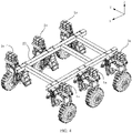
- Fig. 4 is a perspective schematic view of the suspension damping device installed at the chassis.
- the vehicle frame 11 is fixed at the chassis 20, in which the vehicle frame 11 is fixed at the chassis 20 through screws (not shown) to bear a robot (not shown) or a mobile vehicle (not shown) thereon.
- the suspension damping device 10 further includes a wheel set 15, the wheel set 15 is arranged at the steering device 14 to face toward to and contact to the horizontal plane R. The wheel set 15 changes a moving direction of the whole mobile robot according to the manipulation of the steering device 14.
- the wheel set 15 encounters an obstacle such as a rock or a cavity during the movement.
- the damping device 13 of the suspension damping device 10 will drive the wheel set 15 to move up and down during crossing the obstacle.
- the damping device 13 can maintain the wheel set 15 in contact to the road surface R at any time in addition to maintain the balance of the entire mobile robot during the movement of the mobile robot.
- the damping device 13 can also drive the wheel set 15 to move up and down to reduce the oscillation when the mobile robot crosses the obstacle, so that the mobile robot can cross the road surface R smoothly.
- the number of the damping device 13 of the suspension damping device 1a can be two, and the two damping devices 13 are respectively arranged on both sides of the controlling arm sets (as shown in Fig. 2 ).
- the damping devices 13 at both side of the controlling arm set 12 can improve the damping accuracy and further optimize the damping effect.
- Each of the damping device 13 can also selectively replaced with the elastic assemblies, so as to loosening or tightening the elastic assemblies to modify the load-bearing capacity of the chassis 20.
- Fig. 5 is a perspective schematic view of a suspension damping device in accordance with the present invention
- Fig. 6 is a side view of the suspension damping device
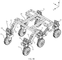
- Fig. 7 is a perspective schematic view of the suspension damping device installed at a chassis of a mobile robot.
- the suspension damping device 1b in this embodiment is similar to the aforementioned suspension damping device 1a, so the same components are denoted by the same reference numerals, and will not be repeated herein.
- the difference between the suspension damping device 1b and the suspension damping device 1a is that one end of the damping device 13 relative to the road surface R is hinged to the chassis 20, and the other end of the damping device 13 facing the road surface R is hinged to the lower controlling arm 122.
- a vehicle frame hinged bracket 16 is parallel to the ground R and perpendicular to the steering device 14, and two ends of each the vehicle frame hinged brackets 16 are respectively hinged to vehicle frame 11 in two opposite suspension damping devices 1b. Accordingly, the two opposite suspension damping devices 1b and the chassis 20 are linked to form a closed frame, so as to improve the fixing strength of the suspension damping device 1b.
- the closed frame constructed by the suspension damping devices 1b and the chassis 20 can reduce the amount of deformations of the suspension damping device 1b in +y or -y directions during the movement of the chassis 20.
- Fig. 8 is a side view of a suspension damping device in another embodiment disclosed by the present invention
- Fig. 9 is a perspective schematic view of the suspension damping device in another embodiment disclosed by the present invention
- Fig. 10 is a perspective schematic view of the suspension damping device installed at a chassis of a mobile robot disclosed by the present invention.
- the suspension damping device 1c includes a wheel set hinged seat 123, one end of the wheel set hinged seat 123 is hinged to the vehicle frame 11 and the other end of the wheel set hinged seat 123 is hinged to the steering device 14.
- the wheel set hinged seat 123 includes a recess 124 (as an arrow shown in Fig. 9 ), the recess 124 is provided for accommodating the damping device 13, where one end of the damping device 13 is hinged to the vehicle frame 11 and the other end faced to the road surface R is hinged to the recess 124.
- the vehicle frame 11, the wheel set hinged seat 123 and the damping device 13 form a triangle, and the suspension damping device 1c can control a motion stability of the steering device 14 through the wheel set hinged seat 123.
- the two ends of the damping device 13 of the suspension damping devices 1a, 1b, and 1c are respectively hinged to the vehicle frame 11 and the steering device 14.
- the suspension damping device 13 can drive the wheel set 15 to move up and down and can maintain the wheel set 15 in contact to the road surface R at a front angle to maintain the balance of the running chassis 20, so that the chassis 20 equipped with the suspension damping devices 1a, 1b and 1c can smoothly cross the obstacles.
- the present invention further discloses another suspension device.
- Fig. 11A is a side view of the suspension assembly in accordance with the present invention
- Fig. 11B is a stereogram schematic view of the suspension assembly in accordance with the present invention.
- the suspension assembly 2a at least includes a supporting arm set 30, a suspension spring assembly 32, a steering supporting frame 34, a steering mechanism 36 (i.e., a steering device), a hub motor 38, and a wheel set 40, where the supporting arm set 30 is composed by a first supporting arm 302 and a second supporting arm 304.
- the suspension spring assembly 32 is arranged between the first supporting arm 302 and the second supporting arm 304, and two ends of the suspension spring assembly 32 are respectively hinged to two ends of the first supporting arm 302 and the second supporting arm 304.
- the shape of the first supporting arm 302 and the second supporting arm 304 are rectangular ribs, so that the rectangular ribs as the first supporting arm 302 and the second supporting arm 304 can be separately arranged on the left and right sides of the suspension spring assembly 32, or respectively arranged on the above and below the suspension spring assembly 32.
- the number of the rectangular ribs as the first supporting arm 302 and the second supporting arm 304 can be one or two, the purpose of the number of the rectangular ribs is to allow the suspension spring assembly 32 to have a supporting point, and the suspension spring assembly 32 is pivotally connected to the first supporting arm 302 and the second supporting arm 304 in a hinged manner, so that the suspension spring assembly 32 can move in the Y direction and Z direction.
- the shape of one of the first supporting arm 302 and the second supporting arm 304 has a U-shaped structure, and the other can be a rectangular rib, and the two sides of the U-shaped structure are extended outward to hinge to the suspension spring assembly 32.
- the shape of the second supporting arm 304 can be a rectangular rib and is arranged below the first supporting arm 302 and respectively arranged on both sides of the suspension spring assembly 32.
- the shape of the first supporting arm 302 is a rectangular rib
- the shape of the second supporting arm 304 is a U-shaped structure, so the first supporting arm 302 is arranged on both sides of the suspension spring assembly 32, and the second supporting arm 304 is arranged below the suspension spring assembly 32 and also under the first supporting arm 302.
- the load capacity of the robot (not shown) or mobile vehicles (not shown) can be adjusted by adjusting the suspension spring assembly 32.
- There is a screw (not shown) at one end of the suspension spring assembly 32 the screw is used to adjust the elastic force of the suspension spring assembly 32, so the tighten or the loosen is adjusted by the loading weight of the robot (not shown) or the mobile vehicle (not shown) to adopt the change of the loading capacity.
- the load capacity of the robot or the mobile vehicle is adjusted by adjusting the suspension spring assembly 32.
- the steering supporting frame 34 is respectively hinged to one end of the first supporting arm 302 and the second supporting arm 304, and the other end of the steering supporting frame 34 is hinged to the steering mechanism 36.
- One end of the steering mechanism 36 facing to the horizontal plane is pivotally connected to the wheel set 40.
- the wheel set 40 further includes a hub motor 38, and the hub motor 38 is used to provide a positive or a negative torque according to the controller (not shown) to drive the traveling direction of the wheel set 40.
- the suspension assembly 2a further includes an auxiliary wheel-lifting supporting frame 42, and the auxiliary wheel-lifting supporting frame 42 is respectively hinged to the other end of the first supporting arm 302 and the second supporting arm 304, and the other end of the auxiliary wheel-lifting supporting frame 42 is fixedly connected to the robot (not shown) or the mobile vehicle (not shown), so that the auxiliary wheel-lifting supporting frame 42 constitutes a linkage mechanism with the supporting arm set 30 and the steering supporting frame 34.
- the linkage mechanism is used to control the movement trajectory of the wheel set 40 when the wheel set 40 encounters a vertical obstacle.
- the supporting arm set 30, the auxiliary wheel-lifting supporting frame 42 and the steering supporting frame 34 of the suspension assembly 2a constitute the linkage mechanism, when the wheel set 40 of the suspension assembly 2a encounters a vertical obstacle, the linkage mechanism can control the movement trajectory of the wheel set 40.
- the suspension assembly 2a includes a maximum compression height and a compression stroke, where the compression height is a height H between the steering mechanism 36 and the bottom of the wheel set 40 (as shown in Fig. 11A ).
- the compression height H of the suspension assembly 2a to the wheel set 40 is 300 mm.
- the compression stroke of the suspension assembly 2a refers to the height at which the suspension assembly 2a lifts the wheel set 40 from the ground, and the compression stroke ranges from 0 to 200 mm.
- Fig. 12A is a perspective structure schematic view of a suspension assembly in another embodiment in accordance with the present invention
- Fig. 12B is a side view of the suspension assembly in another embodiment in accordance with the present invention.
- the difference between Fig. 11A to Fig. 11B is that the suspension assembly 2b further includes a suspension fixing seat 502 and an auxiliary wheel-lifting spring assembly 506.
- the suspension assembly 2b at least includes a suspension fixing seat 502, an auxiliary wheel-lifting supporting frame 504, the auxiliary wheel-lifting spring assembly 506, a supporting arm set 508, a suspension spring assembly 510, a steering supporting frame 512 and a steering mechanism 514.
- the wheel set 518 is pivotally connected to one end of the steering mechanism 514 faced toward the horizontal plane direction, and a hub motor 516 is pivotally connected to the wheel set 518 to drive the wheel set 518.
- one end 502A of the suspension fixing seat 502 is fixedly connected to the robot (not shown) or the mobile vehicle (not shown), and one end of the auxiliary wheel-lifting supporting frame 504 is hinged to the other end 502B of the suspension fixing seat 502.
- One end of the auxiliary wheel-lifting spring assembly 506 is passed through and is hinged to the suspension fixing seat 502, and the other end of the auxiliary wheel-lifting spring assembly 506 is hinged to the other end of the auxiliary wheel-lifting supporting frame 504.
- the supporting arm set 508 is composed by a first supporting arm 508a and a second supporting arm 508b, one end of the first supporting arm 508a is hinged to the other end of the auxiliary wheel-lifting supporting frame 504, and the other end of the first supporting arm 508a is steering supporting frame 512.
- the second supporting arm 508b is arranged at both side of the auxiliary wheel-lifting supporting frame 504, one end of the second supporting arm 508b is hinged to the auxiliary wheel-lifting supporting frame 504, and the other end of the second supporting arm 508b is hinged to the steering supporting frame 512.
- the arrangement and the structure of the first supporting arm 508a and the second supporting 508b of the supporting arm set 508 are the same as the supporting arms described above, which will not be repeated herein.
- the objective of the supporting arm set 508 is used to connect the auxiliary wheel-lifting supporting frame 504 and the steering supporting frame 512.
- the two ends of the supporting arm set 508 are respectively hinged to the auxiliary wheel-lifting supporting frame 504 and the steering supporting frame 512, so the height of the auxiliary wheel-lifting supporting frame 504 and the steering supporting frame 512 can be adjusted with the heights of entire suspension assembly 2b through the supporting arm set 508.
- the two ends of the suspension spring assembly 510 are respectively hinged to two ends of the first supporting arm 508a and the second supporting arm 508b.
- One end of the steering supporting frame 512 is hinged to one end of the steering mechanism 514, and the other end of the steering mechanism 514 facing to the horizontal plane is pivotally connected to the wheel set 518.
- the supporting arm set 508, the auxiliary wheel-lifting supporting frame 504 and the steering supporting frame 512 of the suspension assembly 2b constitute a linkage mechanism, so the suspension assembly 2b can control the movement trajectory of the wheel set 518 through the linkage mechanism when the wheel set 518 encounters a vertical obstacle.
- the load capacity of the robot (not shown) or the mobile vehicle (not shown) can be adjusted by adjusting the suspension spring assembly 510.
- the load capacity of the robot (not shown) or the mobile vehicle (not shown) is adjusted by adjusting the suspension spring assembly 510.
- the hub motors 38, 516 are used to drive the steering of the wheel sets 40, 518.
- the suspension assembly 2a, 2b also include sensors (not shown) to detect the positions and the speed of the wheel sets 40, 518 and the height between the wheel sets 40, 518 and the horizontal plane. Furthermore, the sensors (not shown) can also monitor the current positions of the steering mechanism 36, 514 and the suspension assemblies 2a, 2b.
- suspension assemblies 2a, 2b further include controllers (not shown) to receive the positions and the speed of the wheel sets 40, 518 and the height between the wheel sets 40, 518 and the horizontal plane detected and transferred by the sensors (not shown) to control the steering of the wheel sets 40, 518 and the suspension height of the suspension assemblies 2a, 2b.
- the wheel sets 40, 518 connected to the suspension assemblies 2a, 2b can provide a positive torque or a negative torque according to the control of the controllers (not shown) to drive the traveling directions of the wheel sets 40, 518, while the wheel set 40, 518 only rotate forward or reverse.
- the friction forces are generated between the wheel sets 40,518 and the vertical surface of the step, and the upward component forces is also generated at the same time.
- the suspension assemblies 2a, 2b compress the wheel sets 40, 518 with a height of 300 mm, and the compression strokes range from 0 to 200 mm.
- This upward component forces overcomes the tension of the suspension spring assemblies 32, 510 under the cooperation of the compression strokes, the wheel sets 40, 518 will be lifted by the suspension assemblies 2a, 2b and move upward along the vertical surface of the step until the wheel set 40, 518 exceeds the vertical surface of the step, and the suspension spring assemblies 32, 510 generate a tension forces in X direction (horizontal direction) to allow the wheel set 40, 518 move forward to complete the obstacle crossing.
- the total load capacity of the robot or the mobile vehicle i.e., the weight of the robot or the mobile vehicle plus the available loading weight, and the available loading weight includes the goods or the people delivered by the robot or the mobile vehicle
- the total load capacity of the robot or the mobile vehicle is 100 kg
- the 6 suspension assemblies are used
- the compression height of each suspension assemblies 2a, 2b to the wheel set 40, 518 is 300 mm
- the compression stoke of the suspension assemblies 2a, 2b ranges from 0 to 200mm.
- the obstacle crossing ability of the robot or the mobile vehicle is proportional to the maximum compression strokes value of the suspension assemblies 2a, 2b.
- the present invention further discloses a six-wheel bionic chassis.
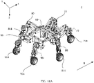
- Fig. 13A is a stereogram schematic view of the six-wheel bionic chassis in one embodiment disclosed by the present invention
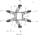
- Fig. 13B is a top view of the six-wheel bionic chassis in an embodiment disclosed by the present invention
- Fig. 13C is a top view of the six-wheel bionic chassis along A-A line segment of Fig. 13B in an embodiment disclosed by the present invention
- Fig. 13D is a side view of the six-wheel bionic chassis in an embodiment disclosed by the present invention.
- a six-wheel bionic chassis 3 is composed by at least a chassis frame 60, a front wheel suspension assembly 70, a middle wheel suspension assembly 80 and a rear wheel suspension assembly 90.
- the chassis frame 60 further includes an upper surface and a bottom surface, in which the bottom surface is a surface that facing the ground (or road surface), so the front wheel suspension assembly 70, the middle wheel suspension assembly 80 and the rear wheel suspension assembly 90 are arranged on the surface that facing to the road surface.
- the front wheel suspension assemblies 70 are arranged at both sides of the front end of the chassis frame 60 (right side of Fig. 13A and Fig.
- the middle wheel suspension assemblies 80 are arranged between the front end and the rear end of the chassis frame 60, and the rear wheel suspension assemblies 80 are arranged at both sides of the rear end of the chassis frame 60 (left side of Fig. 13A and Fig. 13B ).
- the front wheel suspension assembly 70, the middle wheel suspension assembly 80 and the rear wheel suspension assembly 90 are pivotally connected to a front wheel set 718, a middle wheel set 814 and a rear wheel set 914 respectively.
- the middle wheel suspension assembly 80 can be arranged at middle of the chassis frame 60, a position near the front end or the rear end of the chassis frame 60 according to user's design.
- the front wheel suspension assemblies 70, the middle wheel suspension assemblies 80 and the rear wheel suspension assemblies 90 are symmetrically arranged at the chassis frame 60, so in order to simply the description of the structure of the six-wheel bionic chassis 3, the following description is to state one front wheel suspension assembly 70, one middle wheel suspension assembly 80 and one rear wheel suspension assembly 90.
- the arrow M indicates the traveling direction of the six-wheel bionic chassis 3.
- the front wheel suspension assembly 70 at least includes a front wheel upper supporting arm set 708, a front wheel suspension spring assembly 710, a front wheel steering supporting frame 712, a front wheel steering mechanism 714, a front wheel hub motor 716 and a front wheel set 718, in which one end of the front wheel auxiliary supporting frame 704 is hinged to the front end of the chassis frame 60.
- the front wheel upper supporting arm set 708 is composed by a first front wheel upper supporting arm 708a and a pair of second front wheel upper supporting arm 708b, one end of the first front wheel upper supporting arm 708a is hinged to the other end of the front wheel auxiliary wheel-lifting supporting frame 704, and the other end of the first front wheel upper supporting arm 708a is hinged to the front wheel steering supporting frame 712.
- the pair of the second front wheel upper supporting arms 708b are respectively arranged at both sides of the front wheel auxiliary wheel-lifting supporting frame 704, one end of the second front wheel upper supporting arms 708b are hinged to one end of the front wheel auxiliary wheel-lifting supporting frame 704, and the other end of the second front wheel upper supporting arms 708b are hinged to the front wheel steering frame 712.
- the arrangement of the first front wheel upper supporting arm 708a is arranged at the front wheel auxiliary wheel-lifting supporting frame 704 and the front wheel steering supporting frame 712 is that the first front wheel supporting arm 708a is arranged above the second front wheel upper supporting arms 708b.
- the first front wheel upper supporting arm 708a is an inverted U-shaped structure, and the two sides of the inverted U-shaped structure are extended outward to separately hinge to the front wheel auxiliary wheel-lifting supporting frame 704 and the front wheel steering supporting frame 712.
- the second front wheel upper supporting arms 708b is a pair of rectangular ribs, which are respectively arranged at both sides of the front wheel auxiliary wheel-lifting supporting frame 704 and the front wheel steering supporting frame 712, and the pair of the second front wheel upper supporting arms 708b are arranged below the inverted U-shaped structure first front wheel upper supporting arm 708a.
- the objective of the front wheel upper supporting arm set 708 is used to connect the front wheel auxiliary wheel-lifting supporting frame 704 and the front wheel steering supporting frame 712. Since the two ends of the front wheel upper supporting arm set 708 are hinged to the front wheel auxiliary wheel-lifting supporting frame 704 and the front wheel steering supporting frame 712, so the heights of the front wheel auxiliary wheel-lifting supporting frame 704 and the front wheel steering supporting frame 712 are adjusted according to the height of the whole six-wheel bionic chassis 3 by the front wheel upper supporting arm set 708.
- the front wheel suspension spring assembly 710 is placed in a space which is constructed by the first front wheel upper supporting arm 708a and the pair of the second front wheel upper supporting arms 708b, and the two ends of the front wheel suspension spring assembly 710 are respectively hinged to the two ends of the first front wheel upper supporting arm 708a and the second front wheel upper supporting arms 708b.
- One end of the front wheel steering supporting frame 712 is fixedly connected to one end of the front wheel steering mechanism 714, the other end faced along a ground direction is pivotally connected to the front wheel set 718, and the front wheel set 718 is pivotally connected to the front wheel hub motor 716.
- a front wheel linkage mechanism is constituted by the front wheel upper supporting arm set 708, the front wheel auxiliary wheel-lifting supporting frame 704 and the front wheel steering supporting frame 712 of the front wheel suspension 70, so the six-wheel bionic chassis 3 can control a movement trajectory of the front wheel set 718 through the front wheel linkage mechanism when the front wheel set 718 encounters a vertical obstacle.
- the middle wheel suspension assembly 80 at least includes a middle wheel upper supporting arm set 804, a middle wheel suspension spring assembly 806, a middle wheel steering supporting frame 808, a middle wheel steering mechanism 810, a middle wheel hub motor 812 and a middle wheel set 814.
- the middle wheel upper supporting arm set 804 is composed by a first middle wheel upper supporting arm 804a and a pair of the second middle wheel upper supporting arms 804b, one end of the first middle wheel upper supporting arm 804a is hinged to the chassis frame 60, the other end of the first middle wheel upper supporting arm 804a is hinged to the middle wheel steering supporting frame 808, one ends of the pair of the second middle wheel upper supporting arms 804b are hinged to the chassis frame 60, and the other ends of the second middle wheel upper supporting arms 804b are hinged to the middle wheel steering supporting frame 808, in which the first middle wheel upper supporting arm 804a is arranged above the second middle wheel upper supporting arms 804b.
- the middle wheel suspension spring assembly 806 is arranged in a space composed by the first middle wheel upper supporting arm 804a and the middle wheel upper supporting arms 804b, and two ends of the middle spring assembly 806 are respectively hinged to the two ends of the first middle wheel upper supporting arm 804a and the middle wheel upper supporting arms 804b.
- the first middle wheel upper supporting arm 804a has an inverted U-shaped structure, and the two sides of the inverted U-shaped structure are extended outward to hinged to the chassis frame 60.
- the second middle wheel upper supporting arms 804b are a pair of rectangular ribs, in which one ends of the second middle wheel upper supporting arms 804b are hinged to middle of the chassis frame 60, the other ends of the second middle wheel upper supporting arms 804b are hinged to the middle wheel steering supporting frame 808 and arranged below the first middle wheel upper supporting arm 804a.
- the objective of the middle upper supporting arm set 804 is used to connected to the chassis frame 60 and the middle wheel steering supporting frame 808.
- a middle wheel linkage mechanism is constituted by the middle wheel upper supporting arm set 804 and the middle wheel steering supporting frame 808, so the six-wheel bionic chassis 3 can control a movement trajectory of the middle wheel set 814 when the middle wheel set 804 encounters a vertical obstacle.
- the rear wheel suspension assembly 90 at least includes a rear wheel upper supporting arm set 904, a rear wheel suspension spring assembly 906, a rear wheel steering supporting frame 908, a rear wheel steering mechanism 910, a rear wheel hub motor (not shown) and a rear wheel set 914.
- the rear wheel upper supporting arm set 904 is composed by a first rear wheel upper supporting arm 904a and a pair of second rear wheel upper supporting arms 904b, one end of the first rear wheel upper supporting arm 904a is hinged to the rear end of the chassis frame 60, the other end of the first rear wheel upper supporting arm 904a is hinged to the rear wheel steering supporting frame 908, one ends of the second rear wheel upper supporting arms 904b are hinged to the rear end of the chassis frame 60, and the other end of the second rear wheel upper supporting arms 904b are hinged to the rear wheel steering supporting frame 908, in which the first rear wheel upper supporting arm 904a is arranged above the pair of the second rear wheel upper supporting arms 904b.
- the rear wheel suspension spring assembly 906 is arranged in a space composed by the first rear wheel upper supporting arm 904a and the second rear wheel upper supporting arms 904b, and two ends of the rear wheel suspension spring assembly 906 are hinged respectively to the two ends of the first rear wheel upper supporting arm 904a and the second rear wheel upper supporting arms 904b.
- the first rear wheel upper supporting arm 904a has an inverted U-shaped structure, and the two sides of the inverted U-shaped structure are extended outward to separately hinged to the chassis frame 60 and the rear wheel steering supporting frame 908.
- the pair of the second rear wheel upper supporting arms 904b are a pair of rectangular ribs, one ends of the second rear wheel upper supporting arms 904b are hinged to the rear end of the chassis frame 60, the other ends of the rear wheel upper supporting arms 904b are hinged to both sides of the rear wheel steering supporting frame 908, and the rear wheel upper supporting arms 904b are arranged below the inverted U-shaped first rear wheel supporting arm 904a.
- the objective of the rear wheel upper supporting arm 904 is used to connect the rear end of the chassis frame 60 and the rear wheel steering supporting frame 908.
- One end of the rear wheel steering supporting frame 809 is fixedly connected to the rear wheel steering mechanism 910, the other end faced along a ground direction is pivotally connected to the rear wheel set 914, and the rear wheel set 914 is pivotally connected to the rear wheel hub motor (not shown).
- a rear wheel linkage mechanism is constituted by the rear wheel upper supporting arm set 904 and the rear wheel steering supporting frame 908 of the rear wheel suspension assembly 90, so the six-wheel bionic chassis 3 can control a movement trajectory of the rear wheel set 914 through the rear wheel linkage mechanism when the rear wheel set 914 encounters a vertical obstacle.
- first front wheel upper supporting arm 708a of the front wheel upper supporting arm set 708, the first middle wheel upper supporting arm 804a of the middle wheel upper supporting arm set 804 and the first rear wheel upper supporting arm 904a of the rear wheel upper supporting arm set 904 can be an inverted U-shaped structure described above.
- first front wheel upper supporting arm 708a of the front wheel upper supporting arm set 708, the first middle wheel upper supporting arm 804a of the middle wheel upper supporting arm set 804 and the first rear wheel upper supporting arm 904a of the rear wheel upper supporting arm set 904 can also be a pair of rectangle ribs, in which the connecting method are the same as the inverted U-shaped structure which will not describe herein.
- the front wheel suspension assembly 90, the middle wheel suspension assembly 80 and the rear wheel suspension assembly 90 have compression heights and compression strokes respectively, in which the compression heights are the height H (as shown in Fig. 13C ) between top of the steering mechanisms (such as the front wheel steering mechanism 714, the middle wheel steering mechanism 810 or the rear wheel steering mechanism 910) and bottom of the wheel sets (such as the front wheel set 718, the middle wheel set 814 or the rear wheel set 914).
- the compression heights H of the front wheel suspension assembly 70, the middle wheel suspension assembly 80 and the rear wheel suspension assembly 90 to the wheel sets are 300 mm.
- the compression strokes of the front wheel suspension assembly 70, the middle wheel suspension assembly 80 and the rear wheel suspension assembly 90 refer the heights at which the front wheel suspension assembly 70, the middle wheel suspension assembly 80 or the rear wheel suspension assembly 90 respectively lift the front wheel set 718, the middle wheel set 814 or the rear wheel set 914 from the ground.
- the compression stroke ranges from 0 to 200 mm.
- the six-wheel bionic chassis 3 encounters a vertical obstacle and the height of the vertical obstacle cannot be crossed by lifting the front wheel set 718 of the six-wheel bionic chassis 3, at this time the pressing forces produced from the middle wheel set 814 and the rear wheel set 914 to the front wheel set 718 can compress the front wheel suspension assembly 70, so to cross the obstacle through lifting the front wheel set 718 driven by the front wheel upper supporting arm set 708, the front wheel auxiliary supporting frame 704 and the front wheel steering supporting frame 712 of the front wheel linkage mechanism.
- the two ends of the middle wheel upper supporting arm set 804 of the middle wheel suspension assembly 80 are respectively hinged to the chassis frame 60 and the middle wheel steering supporting frame 808, and the two ends of the rear wheel upper supporting arm set 904 of the rear wheel suspension assembly 90 are respectively hinged to the chassis frame 60 and the rear wheel steering supporting frame 908.
- the middle wheel upper supporting arm set 804 and the rear wheel upper supporting arm set 904 can not only move along Y direction but also move along Z direction, such as motions of arthropod's legs.
- the middle wheel upper supporting arm set 804 and the rear wheel upper supporting arm set 904 can respectively move along different directions, so the middle wheel upper supporting arm set 804 and the rear wheel upper supporting arm set 904 can respectively drive the middle wheel steering supporting frame 808 and the rear wheel steering supporting frame 908 to cross the obstacle by lifting the middle wheel set 814 and the rear wheel set 914.
- Fig. 14A is a stereogram schematic view of a six-wheel bionic chassis in another embodiment disclosed by the present invention
- Fig. 14B is a top view of the six-wheel bionic chassis in another embodiment disclosed by the present invention
- Fig. 14C is a cross-sectional view of the six-wheel bionic chassis along B-B line segment of Fig. 14B in another embodiment disclosed by the present invention.
- the front wheel suspension assembly 70 of the six-wheel bionic chassis 3 further has a front wheel suspension fixing seat and a front wheel auxiliary wheel-lifting spring assembly
- the middle wheel suspension assembly 80 further has a middle wheel suspension fixing seat
- the rear wheel suspension assembly 90 further has a rear wheel suspension fixing seat, in which the structures and the functions of these elements will be described below in detail.
- the six-wheel bionic chassis 4 is at least composed by a chassis frame 60, a front wheel suspension assembly 70, a middle wheel suspension assembly 80 and a rear wheel suspension assembly 90, in which the chassis frame 60 includes an upper surface and a bottom surface, and the bottom surface is a surface faced along a ground direction.
- the front wheel suspension assembly 70, the middle wheel suspension assembly 80 and the rear wheel suspension assembly 90 are arranged at the surface faced to the ground, the front wheel suspension assemblies 70 are arranged at both sides (right side of Fig. 14A and Fig.
- the middle wheel suspension assemblies 80 are arranged between the front end and the rear end of the chassis frame 60, and the rear wheel suspension assemblies 90 are arranged at both sides (left side of the Fig. 14A and Fig. 14B ) of the rear end of the chassis frame 60.
- the front wheel suspension assembly 70, the middle wheel suspension assembly 80 and the rear wheel suspension assembly 90 are further pivotally connected to a front wheel set 718, a middle wheel set 814 and a rear wheel set 914, respectively.
- the middle wheel suspension assembly 80 can be arranged at middle of the chassis frame 60, a position near the front end of the chassis frame 60 or near the rear end of the chassis frame 60 according to user's design.
- Fig. 14C is a cross-sectional view along B-B line segment of Fig. 14B .
- the front wheel suspension assemblies 70, the middle wheel suspension assemblies 80 and rear wheel suspension assemblies 90 are lateral symmetry and arranged at the chassis frame 60, so the six-wheel bionic chassis 4 described below will be explained by a single front wheel suspension assembly 70, a single middle wheel suspension assembly 80 and a single rear wheel suspension assembly 90.
- the arrow M indicates the traveling direction of the six-wheel bionic chassis 4 in Fig. 14A to Fig. 14C .
- the front wheel suspension assembly 70, the middle wheel suspension assembly 80 and the rear wheel suspension assembly 90 have compression heights and compression strokes respectively, in which the compression heights are the height H (as shown in Fig. 14C ) between top of the steering mechanism (such as the front wheel steering mechanism 714, the middle wheel steering mechanism 810 or the rear wheel steering mechanism 910) and bottom of the wheel sets (such as the front wheel set 718, the middle wheel set 814 or the rear wheel set 914).
- the compression heights H between the front wheel steering mechanism 714, the middle wheel steering mechanism 810 or the rear wheel steering mechanism 910 and the front wheel set 718, the middle wheel set 814 or the rear wheel set 914 are 300 mm.
- the compression strokes of the front wheel steering mechanism 714, the middle wheel steering mechanism 810 or the rear wheel steering mechanism 910 refer the heights at which the front wheel steering mechanism 714, the middle wheel steering mechanism 810 or the rear wheel steering mechanism 910 respectively lift the front wheel set 718, the middle wheel set 814 or the rear wheel set 914 from the ground.
- the compression strokes range from 0 to 200 mm.
- the pressing forces produced from the middle wheel set 814 and the rear wheel set 914 can compress the front wheel suspension assembly 70, so to cross the vertical obstacle through lifting the front wheel upper supporting arm set 708 driven by the front wheel auxiliary wheel-lifting supporting frame 704 and the front wheel steering mechanism 712 of the front wheel linkage mechanism.
- the two ends of the middle wheel upper supporting arm set 804 of the middle wheel suspension assembly 80 are respectively hinged to the chassis frame 60 and the middle wheel steering mechanism 808, and the two ends of the rear wheel upper supporting arm set 904 of the rear wheel suspension assembly 90 are respectively hinged to the chassis frame 60 and the rear wheel steering mechanism 908.
- the middle wheel upper supporting arm set 804 and the rear wheel upper supporting arm set 904 can not only move along Y direction but also move along Z direction, such as motions of arthropod's legs.
- the middle wheel upper supporting arm set 804 and the rear wheel upper supporting arm set 904 can respectively move along different directions, so the middle wheel upper supporting arm set 804 and the rear wheel upper supporting arm set 904 can respectively drive the middle wheel steering supporting frame 708 and the rear wheel steering supporting frame 808 to cross the obstacle by lifting the middle wheel set 814 and the rear wheel set 914.
- Fig. 15A is a schematic view of the front wheel suspension assembly of the six-wheel bionic chassis disclosed by the present invention
- Fig. 15B is a side view of the front wheel suspension assembly.
- the front wheel suspension assembly 70 at least includes a front wheel suspension fixing seat 702, a front wheel auxiliary supporting frame 704, a front wheel auxiliary wheel-lifting spring assembly 706, a front wheel upper supporting arm set 708, a front wheel suspension spring assembly 710, a front wheel steering supporting frame 712, a front wheel steering mechanism 714, a front wheel hub motor 716 and a front wheel set 708, in which one end 702A of the front wheel suspension fixing seat 702 is fixedly connected to the front end of the chassis frame 60, and one end of the front wheel auxiliary supporting frame 704 is hinged to the other end 702B of the front wheel suspension fixing seat 702.
- One end of the front wheel auxiliary wheel-lifting spring assembly 706 is passed through and arranged at the front wheel suspension fixing seat 702, the front wheel auxiliary wheel-lifting spring assembly 706 is also hinged to the front wheel suspension fixing seat 702, and the other end of the front wheel auxiliary wheel-lifting spring assembly 706 is hinged to the other end of the front wheel auxiliary wheel-lifting supporting frame 704.
- the front wheel upper supporting arm set 708 is composed by a first front wheel upper supporting arm 708a and a pair of second front wheel upper supporting arms 708b, in which one end of the first front wheel upper supporting arm 708a is hinged to the other end of the front wheel auxiliary wheel-lifting supporting frame 704, and the other end of the first front wheel upper supporting arm 708a is hinged to the front wheel steering supporting frame 712.
- the pair of the second front wheel upper supporting arms 708b are arranged at both sides of the front wheel auxiliary wheel-lifting supporting frame 704, in which one ends of the second front wheel upper supporting arms 708b are hinged to the front wheel auxiliary wheel-lifting supporting frame 704, and the other ends of the second front wheel upper supporting arms 708b are hinged to the front wheel steering supporting frame 712.
- the arranging method of the first front wheel upper supporting arm 708a which arranged at the front wheel auxiliary wheel-lifting supporting frame 704 and the front wheel steering supporting frame 708a is that the first front wheel upper supporting arm 708a is arranged above the second front wheel upper supporting arms 708b.
- the first front wheel upper supporting arm 708a has an inverted U-shaped structure, and the two sides of the inverted U-shaped structure are extended outward to separately hinged to the front wheel auxiliary wheel-lifting supporting frame 704 and the front wheel steering supporting frame 712.
- the second front wheel upper supporting arms 708b are a pair of rectangular ribs, and the second front wheel upper supporting arms 708b are respectively arranged at both sides of the front wheel auxiliary wheel-lifting supporting frame 704 and the front wheel steering supporting frame 712.
- the objective of the front wheel upper supporting arm set 708 is used to connect to the front wheel auxiliary wheel-lifting supporting frame 704 and the front wheel steering supporting frame 712.
- the two ends of the front wheel upper supporting arm set 708 are respectively hinged to the front wheel auxiliary wheel-lifting supporting frame 704 and the front wheel steering supporting frame 712, so the front wheel auxiliary wheel-lifting supporting frame 704 and the front wheel steering supporting frame 712 can adjust the heights by the front wheel upper supporting arm set 708 according to the heights of the six-wheel bionic chassis 3 (as shown in Fig. 13A ) or 4 (as shown in Fig. 14A ).
- the two ends of the front wheel suspension spring assembly 710 are respectively hinged to two ends of the first front wheel upper supporting arm 708a and the second front wheel upper supporting arms 708b.
- a front wheel linkage mechanism is constituted by the front wheel upper supporting arm set 708, the front wheel auxiliary wheel-lifting supporting frame 704 and the front wheel steering supporting frame 712 of the front wheel suspension assembly 70, so the six-wheel bionic chassis 3 or 4 can control a movement trajectory through the front wheel linkage mechanism when the front wheel set 718 encounters a vertical obstacle.
- Fig. 16 is a structural view of the middle wheel suspension assembly of the six-wheel bionic chassis.
- the middle wheel suspension assembly 80 at least includes a middle wheel suspension fixing seat 802, a middle wheel upper supporting arm set 804, a middle wheel suspension spring assembly 806, a middle wheel steering supporting frame 808, a middle wheel steering mechanism 810, a middle wheel hub motor 812 and a middle wheel set 814, in which one end 802A of the middle wheel suspension fixing seat 802 is fixedly connected to middle of the chassis frame 60.
- the middle wheel upper supporting arm set 804 is composed by a first middle wheel upper supporting arm 804a and a pair of second middle wheel upper supporting arms 804b, one end of the first middle wheel upper supporting arm 804a is hinged to the other end 802B of the middle wheel suspension fixing seat 802, and the other end of the first middle wheel upper supporting arm 804a is hinged to the middle wheel steering supporting frame 808.
- One ends of the second middle wheel upper supporting arms 804b are hinged to the other end 802B of the middle wheel suspension fixing seat 802, and the other ends of the second middle wheel upper supporting arms 804b are hinged to the middle wheel steering supporting frame 808, in which the first middle wheel upper supporting arm 804a is arranged above the second middle wheel upper supporting arms 804b.
- the first middle wheel upper supporting arm 804a has an inverted U-shaped structure, and the two sides of the inverted U-shaped structure are extended outward to separately hinge to the middle wheel suspension fixing seat 802 and the middle wheel steering supporting frame 808.
- the second middle wheel upper supporting arms 804b are a pair of rectangular ribs, in which the second middle wheel upper supporting arms 804b are respectively arranged at both sides of the middle wheel suspension fixing seat 802 and the middle wheel steering supporting frame 808, and the second middle wheel upper supporting arms 804b are arranged below the first middle wheel upper supporting arm 804a.
- the objective of the middle wheel upper supporting arm set 804 is used to connect to the middle wheel suspension fixing seat 802 and the middle wheel steering supporting frame 808.
- One end of the middle wheel steering supporting frame 808 is fixedly connected to the middle wheel steering mechanism 810, the other end faced along a ground direction of the middle wheel steering supporting frame 808 is pivotally connected to the middle wheel set 814, and the middle wheel set 814 is pivotally connected to the middle wheel hub motor 812.
- a middle wheel linkage mechanism is constituted by the middle wheel upper supporting arm set 804 and the middle wheel steering supporting frame 808 of the middle wheel suspension assembly 80, so the six-wheel bionic chassis 3 or 4 can control a movement trajectory of the middle wheel set 814 through the middle wheel linkage mechanism when the middle wheel set 814 encounters a vertical obstacle.
- Fig. 17 is a structural view of a rear wheel suspension assembly of the six-wheel bionic chassis.
- the rear wheel suspension assembly 90 at least includes a rear wheel suspension fixing seat 902, a rear wheel upper supporting arm set 904, a rear wheel suspension spring assembly 906, a rear wheel steering supporting frame 908, a rear wheel steering mechanism 910, a rear wheel hub motor 912 and a rear wheel set 914, in which one end 902A of the rear wheel suspension fixing seat 902 is fixedly connected to the rear end of the chassis frame 60.
- the rear wheel upper supporting arm set 904 is composed by a first rear wheel upper supporting arm 904a and a pair of the second rear wheel upper supporting arms 904b, one end of the first rear wheel upper supporting arm 904a is hinged to the other end 902B of the rear wheel suspension fixing seat 902, the other end of the first rear wheel upper supporting arm 904a is hinged to the rear wheel steering supporting frame 908, one ends of the second rear wheel upper supporting arms 904b are hinged to the other end 902B of the rear wheel suspension fixing seat 902, and the other ends of the second rear wheel upper supporting arms 904b are hinged to the rear wheel steering supporting frame 908, in which the first rear wheel upper supporting arm 904a is arranged above the second rear wheel upper supporting arms 904b.
- the first rear wheel upper supporting arm 904a has an inverted U-shaped structure, in which two ends of the inverted U-shaped structure extended outward from the first rear wheel upper supporting arm 904a are respectively hinged to the rear wheel suspension fixing seat 902 and the rear wheel steering supporting frame 908.
- the second rear wheel upper supporting arms 904b are a pair of rectangular ribs, in which the second rear wheel upper supporting arms 904b are arranged at both sides of the rear wheel suspension fixing seat 902 and the rear wheel steering supporting frame 908, and the second rear wheel upper supporting arms 904b are arranged below the first rear wheel upper supporting arm 904a.
- the objective of the rear wheel upper supporting arm set 904 is used to connect to the rear wheel suspension fixing seat 902 and the rear wheel steering supporting frame 908.
- a rear wheel linkage mechanism is constituted by the rear wheel upper supporting arm set 904 and the rear wheel steering supporting frame 908 of the rear wheel suspension assembly 90, so the six-wheel bionic chassis 3 or 4 can control a movement trajectory of the rear wheel set 914 through the rear wheel linkage mechanism when the rear wheel set 914 encounters a vertical obstacle.
- the front wheel hub motor 716 of the front wheel suspension assembly 70, the middle wheel hub motor 812 of the middle wheel suspension assembly 80 and the rear wheel hub motor 912 of the rear wheel suspension assembly 90 of the six-wheel bionic chassis 3, 4 disclosed by the present invention are respectively used to drive the front wheel set 718, the middle wheel set 814 and the rear wheel set 914 to rotate.
- the six-wheel bionic chassis 3, 4 further include sensors (not shown) to detect positions and the speed of the front wheel set 718, the middle wheel set 814 and the rear wheel set 914 and the heights between the front wheel set 718, the middle wheel set 814, the rear wheel set 914 and the horizontal plane.
- the sensors can also simultaneously monitor the current positions of the front wheel steering mechanism 714, the middle wheel steering mechanism 810 and the rear wheel steering mechanism 910 and the suspension assembly 70, the middle wheel suspension assembly 80 and the rear wheel suspension assembly 90.
- the six-wheel bionic chassis 3, 4 include controllers (not shown) to receive the positions and the speed of the front wheel set 718, the middle wheel set 814 and the rear wheel set 914, and the heights between the front wheel set 718, the middle wheel set 814, the rear wheel set 914 and the horizontal plane detected by the sensors, so to respectively control the steering of the front wheel set 718, the middle wheel set 814 and the rear wheel set 914, and the suspension heights of the front wheel suspension assembly 70, the middle wheel suspension assembly 80 and the rear wheel suspension assembly 90.
- the front wheel suspension assembly 70, the middle wheel suspension assembly 80 and the rear wheel suspension assembly 90 can drive the front wheel set 718, the middle wheel set 814 and the rear wheel set 914 to respectively produce 200 mm movement strokes up and down.
- the six-wheel bionic chassis 3, 4 encounter a vertical obstacle and the height of the vertical obstacle cannot be crossed by lifting the front wheel set 718 of the six-wheel bionic chassis 3, 4, at this time the pressing forces produced from the middle wheel set 814 and the rear wheel set 914 can compress the front wheel auxiliary wheel-lifting spring assembly 706 of the front wheel suspension assembly 70, so to cross the vertical obstacle through lifting the front wheel upper supporting arm set 708.
- the obstacle crossing process of the six-wheel bionic chassis 3, 4 will be describe below in detail.
- the front wheel suspension spring assembly 710 of the front wheel suspension assembly 70, the middle wheel suspension spring assembly 806 of the middle wheel suspension assembly 80 and the rear wheel suspension spring assembly 906 of the rear wheel suspension assembly 90 can drive the middle wheel set 814 and the rear wheel set 914 to produce 300 mm obstacle crossing height of movement strokes.
- Fig. 18A shows that the front wheel suspension spring assembly 710, the middle wheel suspension spring assembly 806 and the rear wheel suspension spring assembly 906 of the six-wheel bionic chassis 3, 4 have downward (faced along a ground direction) compression strokes ranges from 0 to 200 mm.
- Fig. 18A shows that the front wheel suspension spring assembly 710, the middle wheel suspension spring assembly 806 and the rear wheel suspension spring assembly 906 of the six-wheel bionic chassis 3, 4 have downward (faced along a ground direction) compression strokes ranges from 0 to 200 mm.
- the front wheel suspension spring assembly 710, the middle wheel suspension spring assembly 806 and the rear wheel suspension spring assembly 906 of the six-wheel bionic chassis 3, 4 are lifted upward to 300 mm height.
- the six-wheel bionic chassis 3, 4 at least have ⁇ 200 mm height of damping strokes.
- the compression height of the wheel sets (the front wheel set 718, the middle wheel set 814 and the rear wheel set 914) are larger, the flexibility of the suspension spring assemblies (the front wheel suspension assembly 70, the middle wheel suspension assembly 80 and the rear wheel suspension assembly 90) are better, and the compression strokes of the suspension assemblies (the front wheel suspension assembly 70, the middle wheel suspension assembly 80 and the rear wheel suspension assembly 90) are larger, so the obstacle crossing ability of the six-wheel bionic chassis 3, 4 are better.
- the suspension damping devices (such as Fig. 1 to Fig. 10 ) or the suspension assemblies (such as Fig. 11A to Fig. 11B and Fig. 12A to Fig. 12B ) described above can also be installed at the six-wheel bionic chassis 3, 4, so the suspension damping devices (such as Fig. 1 to Fig. 10 ) or the suspension assemblies (such as Fig. 11A to Fig. 11B and Fig. 12A to Fig. 12B ) described above can be respectively used as the suspension damping devices or the suspension assemblies of the front wheel, the middle wheel or the rear wheel.
- the six-wheel bionic chassis (not shown) which includes the suspension damping devices (such as Fig. 1 to Fig.
- the suspension damping devices such as Fig. 1 to Fig. 10
- the suspension assemblies such as Fig. 11A to Fig. 11B and Fig. 12A to Fig. 12B ) combined with the chassis will not describe herein.
- Fig. 19 is a schematic view of a six-wheel bionic chassis when crossing an obstacle in an embodiment in accordance with the present invention.
- the six-wheel bionic chassis 3, 4 operate stably at a first peak torque which is 10 N ⁇ m when move on a plane.
- the sensors detect that the front wheel set 718 encounters a vertical obstacle Q, the sensors send obstacle signals to the controller.
- the controller sends controlling signals to the front wheel hub motor 716, the middle wheel hub motor 812 and the rear wheel hub motor 912 to operate at a second peak torque which is 13 N • m.
- the front wheel set 718 is subjected to a reaction force N 3 acted from the vertical obstacle Q and a friction force F 3 acted between the front wheel set 718 and the plane 30, and the front wheel suspension spring assembly 710 is compressed by a resultant force of the reaction force N 3 and the friction force F 3 .
- the front wheel set 718 is subjected to the resultant force of the reaction force N 3 acted from the vertical obstacle Q and the friction force F 3 acted between the front wheel set 718 and the plane 30 to compress the front wheel suspension spring assembly 710 and the front wheel auxiliary wheel-lifting spring assembly 706 of the front wheel suspension assembly 70.
- the front wheel suspension assembly 70 can drive the front wheel set 718 to move along a P direction, and the front wheel set 718 can be lifted to cross the vertical obstacle Q, so to reach the objective of crossing obstacles.
- the six-wheel bionic chassis 3, 4 keep moving forward (along a direction of an arrow M shown in Fig. 19 ), and the controller sends a signal to control the front wheel hub motor 716 to operate at the first peak torque which is 10 N • m.
- the six-wheel bionic chassis 3, 4 keep moving forward and the sensors sense that the middle wheel set 814 encounters the vertical obstacle Q, the sensors send obstacle signals to the controller again, and the controller sends control signals to the middle wheel hub motor 812 to operate at the second peak torque which is 13 N • m after the controller receives the obstacle signals.
- the middle wheel set 814 is subjected to a reaction force N 2 acted from the vertical obstacle Q and a friction force F 2 acted between the middle wheel set 814 and the plane 30, and the middle wheel suspension spring assembly 806 is compressed by a resultant force of the reaction force N 2 and the friction force F 2 .
- the middle wheel set 814 is subjected to the resultant force of the reaction force N 2 acted from the vertical obstacle Q and the friction force F 2 acted between the middle wheel set 814 and the plane 30 to compress the middle wheel suspension spring assembly 806 of the middle wheel suspension assembly 80, and the middle wheel suspension assembly 80 can also drive the middle wheel set 814 to move along the P direction.
- the middle wheel set 814 can cross the vertical obstacle Q in a passive way with the help of traction force and the motive force itself, so to let the middle wheel set 814 reach the objective of crossing obstacles.
- the front wheel hub motor 716, the middle hub motor 812 and rear wheel hub motor 912 operate at the first peak torque which is 10 N ⁇ m to drive the front wheel set 718, the middle wheel set 814 and the rear wheel set 914 to move forward (along the arrow M shown in Fig. 19 ).
- the sensors send the obstacle signals to the controller again.
- the controller After the controller receives the obstacle signals, the controller sends the controlling signal to the rear wheel hub motor 912 to operate at the second peak torque which is 13 N • m.
- the rear wheel set 914 is subjected to a reaction force N 1 acted from the vertical obstacle Q and a friction force F 1 acted between the rear wheel set 914 and the plane 30, so the rear wheel suspension spring assembly 906 is compressed by a resultant force of the reaction force N 1 and the friction force F 1 .
- the rear wheel set 914 is subjected to the resultant force of the reaction force N 1 acted from the vertical obstacle Q and the friction force F 1 acted between the rear wheel set 914 and the plane 30 to compress the rear wheel suspension spring assembly 906 of the rear wheel suspension assembly 90, and the rear wheel suspension assembly 90 can drive the rear wheel set 914 to move along the P direction.
- the rear wheel set 914 can cross the vertical obstacle Q in a passive way with the help of traction force and the motive force itself, so to let the rear wheel set 914 reach the objective of crossing obstacles.
- the controller sends signals to change the front wheel hub motor 716, the middle wheel hub motor 812 and the rear wheel hub motor 912 of the six-wheel bionic chassis 3, 4 from the second peak torque which is 13 N • m to the first peak torque which is 10 N ⁇ m, so to drive the front wheel set 718, the middle wheel set 814 and the rear wheel set 914 to move forward (along the arrow of M shown in Fig.
- the six-wheel bionic chassis 3, 4 adjusts the toughness of the front wheel suspension assembly 70, the middle wheel suspension assembly 80 and the rear wheel suspension assembly 90, the compression strokes from the front wheel suspension assembly 70, the middle wheel suspension assembly 80 and the rear wheel suspension assembly 90 to the front wheel set 718, the middle wheel set 814 and the rear wheel set 914 range from 0 to 200 mm.
- the six-wheel bionic chassis 3, 4 can reach the objective of crossing obstacles with the compression strokes of 300 mm. The calculation process will describe below in detail.
- the factors which influence the obstacle-crossing height of the six-wheel bionic chassis 3, 4 may include: the positions of the gravity center of the six-wheel bionic chassis 3, 4, the hub motors (such as the front wheel hub motor 716, the middle wheel hub motor 812 and the rear wheel hub motor 912), and the friction coefficients between the wheel sets (such as the front wheel set 718, the middle wheel set 814 and the rear wheel set 914) and the ground.
- the positions of the gravity center of the six-wheel bionic chassis 3, 4 relates to the structure factors of the chassis frame 60, in which the structure factors include the diameter of the wheel sets (such as the front wheel set 718, the middle wheel set 814 and the rear wheel set 914), the elasticity of the damping structures, and the suspension strokes.
- L 1 is a length of each of the upper supporting arm set
- L 2 is a length of each of the steering supporting frame
- L 3 is a distance between the center of each of the wheel set (such as the front wheel set 718, the middle wheel set 814 and the rear wheel set 914) when the obstacle crossing is completed and each of the suspension fixing seat (such as the front wheel suspension fixing seat 702, the middle wheel suspension fixing seat 802 and the rear wheel suspension fixing seat 902)
- L 4 is a distance between center of each of the wheel set (such as the front wheel set 718, the middle wheel set 814
- the front wheel set 718, the middle wheel set 814 and the rear wheel set 914 can be calculated to obtain a resultant force of forward forces from six different positions of the six-wheel bionic chassis 3, 4, so to obtain the obstacle crossing height of the six-wheel bionic chassis 3, 4.
- the structures of the front wheel suspension assembly 70, the middle wheel suspension assembly 80 and the rear wheel suspension assembly 90 of the six-wheel bionic chassis 3, 4 disclosed by the present invention can simulate motions of arthropod's legs, so to continuously increase the vertical obstacle crossing ability of the six-wheel bionic chassis 3,4.
Landscapes
- Engineering & Computer Science (AREA)
- Mechanical Engineering (AREA)
- Chemical & Material Sciences (AREA)
- Combustion & Propulsion (AREA)
- Transportation (AREA)
- Automation & Control Theory (AREA)
- Vehicle Body Suspensions (AREA)
- Steering-Linkage Mechanisms And Four-Wheel Steering (AREA)
Abstract
Description
- The present invention relates to chassis machinery technical field, more particularly, a suspension device, a suspension damping device and a six-wheels bionic chassis applying on robots, mobile robots or mobile vehicles. The suspension device and the suspension damping device are used to increase the obstacle-crossing capabilities of the robots, mobile robots or the mobile vehicles.
- In the relate art, an important mechanism in the mobile robot is a suspension damping device. The suspension damping device can decrease oscillations occurred during a movement of the mobile robot, so the mobile robot can work stably. The conventional suspension damping device uses a linear-bearing suspension system. However, the structure of the linear-bearing suspension system is not compact, the dedicated space of the linear-bearing suspension system is large, and the cost of the linear-bearing suspension system is expensive, too. Moreover, when the linear-bearing suspension system is installed at the suspension damping device, a higher processing accuracy is needed on an installing surface. Thus, the life span of the whole suspension damping device is decreased, and the cost is also expensive.
- Furthermore, the vehicle engineering is progressing with the rapid development of technology. A general mobile vehicle is divided into two parts: vehicle body and wheeled chassis. A common wheeled chassis includes at least wheels, a vehicle frame, a steering device (or turning device), a motive supplying device, a brake and a suspension device. Therein, the wheels, the steering device and the suspension system are the most important assemblies to control a moving direction and avoid rollover of the mobile vehicle. The general mobile vehicle will encounter some problems such as turning or obstacles crossing. Therefore, how to keep stable when the mobile vehicle is moving forward and keep smooth when the mobile vehicle is turning are the topics which is keeping studying for vehicle engineering.
- With reference to the turning topic, the wheels and the steering device are core subjects when the mobile vehicle is controlled to turn. The conventional steering device is a single-linkage type steering device, which is characterized in that: the driver can control the tires of the front wheels individually and directly. For example, in a four wheels mobile vehicle, there are two steering devices used to control the two front wheels. When the mobile vehicle wants to turn, the driver will rotate the steering wheel to control the wheels to a predetermined direction that the mobile vehicle wants to turn, the front wheels controlled by the steering device will turn to the predetermined direction, and the rear wheels will be associated to turn to the predetermined direction and move forward. This type of the steering device is enough for the general four-wheels mobile vehicle, however, the single-linkage type steering device can not apply to some special mobile vehicles which have a plurality of wheels, such as a bus or a tank which has many wheels and belts.
- On the other hand, the suspension device of the mobile vehicle is used to stabilize the mobile vehicle, so the mobile vehicle can keep stability in a plurality of moving situations, such as moving on a horizontal plane, climbing along an incline or crossing an obstacle. The suspension device is composed of a spring and a damping cylinder, so the suspension device is viewed as a damping device. For mobile vehicles that the general people use, the suspension device can be an individual suspension device or a non-individual suspension device, in which the individual suspension device is characterized in that the left part and the right part of the wheels are controlled separately, and the non-individual suspension device is characterized in that all wheels of the mobile vehicle are integrally controlled. The suspension devices can be further divided into an active type or a passive type. The deference between the two type suspension devices is that the active suspension device can compute to accommodate different road environments according to elasticity constant and damping coefficient of the suspension devices, and elasticity constant and damping coefficient of the passive suspension device are both fixed, which is not changed due to different environments.
- In recent years, robots are applied on the wheeled chassis of the mobile vehicle. The general robots are usually used at outdoors, the environment with rough ground or a disaster scene, so the wheeled chassis used on the robots need better topographic adaptability and mobility than the wheeled chassis used on the mobile vehicle. Thus, there is still a long way to go for improving the technology when applying the wheeled chassis used on the mobile vehicle on the robots. A conventional mobile vehicle which has a slipknot type suspension device and using method of the slipknot type suspension device thereof is disclosed, in which the disclosed chassis device is used to military mobile vehicles, i.e., the environment with rough ground, and the chassis device has good topographic adaptability, obstacle crossing ability and tires which have good mobility. Nonetheless, the conventional chassis device of the related art cannot drive the robot to climb stairs, turn to different directions or have random moving directions, and the mobility device which the conventional chassis device connected is not disclosed, such as a robot moving device or only has a vehicle body. It is to say that the effect of changing the moving device for operating the chassis is not considered.
- It is an object of the present invention is to provide a suspension damping device, when the suspension damping device is acting, the wheel set can be driven to move up and down, and can maintain the wheel set in contact to the ground or a road surface, so a chassis installed with the suspension damping device can cross obstacles smoothly.
- According to the above objective, the present invention discloses a suspension damping device installed at a chassis of a mobile robot. The suspension damping device includes a vehicle frame, a controlling arm set, a spring damping device and a steering device. The vehicle frame is arranged at the ground and fixed to the chassis. The controlling arm set includes an upper supporting arm and a lower supporting arm, one ends of the upper controlling arm and the lower controlling arm are respectively hinged to the vehicle frame, and the other ends of the upper controlling arm and the lower controlling arm are respectively hinged to the steering device, so the controlling arm set controls the motion stability of the steering device. One end of the damping device opposite to the ground is hinged to the vehicle frame, and the other end of the damping device faced to the ground that is hinged to the steering device.
- The present invention further discloses a suspension damping device installed at a chassis of a mobile robot. The suspension damping device includes a vehicle frame, a controlling arm set, a suspension damping device and a steering device. The vehicle frame is arranged on the ground and fixed to the chassis. The controlling arm set includes an upper controlling arm and a lower controlling arm, one ends of the of the upper controlling arm and the lower controlling arm are respectively hinged to the chassis, and the other ends of the upper controlling arm and the lower controlling arm are respectively hinged to the steering device, so the controlling arm set controls the motion stability of the steering device. The damping device is perpendicular to the ground, one end of the damping device opposite to the ground is hinged to the chassis, and the other end of the damping device faced to the ground is hinged to the lower controlling arm.
- The present invention still further discloses a suspension damping device installed at a chassis of a mobile robot. The suspension damping device includes a vehicle frame, a wheel set hinged seat, a damping device and a steering device. The vehicle frame is arranged on the ground and fixed to the chassis, one end of the wheel set hinged seat is hinged to the vehicle frame and the other end of the wheel set hinged seat is fixed to the steering device, so the wheel set hinged seat controls the motion stability of the steering device. The damping device is arranged on the vehicle frame, one end of the damping device opposite to the ground is hinged to the vehicle frame, the other end of the damping device faced to the ground is arranged on the wheel set hinged seat, and the other end of the damping device is hinged to the wheel set hinged seat.
- In addition, the present invention further discloses a suspension assembly. The suspension assembly can be applied to a robot or a mobile vehicle, so the robot or the mobile vehicle can move on a scraggly surface of the horizontal plane such as an unpaved road or a dirt road to smoothly cross over a deceleration zone or a vertical obstacle.
- The suspension assembly disclosed by the present invention can adjust toughness of the suspension assembly to compress a height of a wheel set, so the robot or the mobile vehicle has a damping stroke corresponding to the positive and negative range the compression height.
- According to the above, the present invention discloses a suspension assembly, includes: a supporting arm set is composed by a first supporting arm and a second supporting arm; a suspension spring assembly is arranged between the first supporting arm and the second supporting arm, and two ends of the suspension spring assembly are respectively hinged to two end of the first supporting arm and the second supporting arm; and a steering supporting frame, one end of the steering supporting frame is hinged to one ends of the first supporting arm and the second supporting arm, the other end of the steering supporting frame is hinged to a steering mechanism, and one end of the steering mechanism faced to the horizontal plane is pivotally connected to a wheel set.
- It is another objective of the present invention is to disclose a six-wheel bionic chassis. The front wheel suspension spring assembly, a middle wheel suspension spring assembly and a rear wheel suspension spring assembly of the six-wheel bionic chassis can drive the wheel set to move up and down, and can maintain front wheel set, middle wheel set and rear wheel set in contact to the horizontal plane to maintain the balance of the six-wheel bionic chassis.
- It is another objective of the present invention is to disclose a six-wheel bionic chassis, the entire structure of the six-wheel bionic chassis is compact, and the load capacity of the six-wheel bionic chassis can be adjusted by adjusting the front wheel suspension spring assembly, the middle wheel suspension spring assembly and the rear wheel suspension spring assembly.
- It is still another objective of the present invention is to disclose a six-wheel bionic chassis that can adjust the toughness of front wheel suspension assembly, middle wheel suspension assembly and rear wheel suspension assembly to compress heights of front wheel set, middle wheel set and rear wheel set, so the entire six-wheel bionic chassis has a damping stroke corresponding to the positive and negative range of the compression height.
- According to the above objectives, the present invention discloses a six-wheel bionic chassis that includes a chassis frame, a controller, a sensor, and front wheel suspension assemblies are pivotally connected to both sides of a front end of the chassis frame toward the horizontal plane, middle wheel suspension assemblies are pivotally connected to middle two sides of the chassis frame, and rear wheel suspension assemblies are pivotally connected to both sides of a rear end of the chassis frame, and the controller and the sensor are electrically connected to the front wheel suspension assemblies, the middle suspension assemblies and the rear wheel suspension assemblies respectively. Each of the front wheel suspension assemblies includes: a front wheel auxiliary wheel-lifting supporting frame, one end of the front wheel auxiliary wheel-lifting supporting frame is hinged to the front end of the chassis frame; a front wheel upper supporting arm set composed by a by a first front wheel upper supporting arm and a pair of second front wheel upper supporting arms, the first front wheel upper supporting arm is arranged above the pair of second front wheel upper supporting arms, one end of the first front wheel upper supporting arm is hinged to the other end of the front wheel auxiliary wheel-lifting supporting frame and the other end of the first front wheel upper supporting arm is hinged to a front wheel steering supporting frame, one end of each of the second front wheel upper supporting arms is hinged to the other end of the front wheel auxiliary wheel-lifting supporting frame and the other end of each of the second front wheel upper supporting arms is hinged to the front wheel steering supporting frame; both ends of a front wheel suspension spring assembly are hinged to the both ends of the front wheel upper supporting arm set; and one end of the front wheel steering supporting frame is fixedly connected to a front wheel steering mechanism, one end of the front wheel steering mechanism faced to a ground direction is pivotally connected to a front wheel set, the front wheel set is pivotally connected to a front wheel hub motor, so the front wheel upper supporting arm set, the front wheel auxiliary wheel-lifting supporting frame and the front wheel steering supporting frame of the front steering assembly constitute a front wheel linkage mechanism to control a movement trajectory of the front wheel set when the front wheel set encounters a vertical obstacle.
- Each of the middle wheel suspension assemblies comprises: a middle wheel upper supporting arm set composed by a first middle wheel upper supporting arm and a pair of second middle upper supporting arms, the first middle upper supporting arm is arranged above the pair of second middle wheel upper supporting arm, one end of the middle wheel upper supporting arm is hinged to the middle of the chassis frame, the other end of the first middle wheel upper supporting arm is hinged to a middle wheel steering supporting frame, one end of each of the second middle wheel upper supporting arms is hinged to the middle of the chassis frame respectively, and the other end of each of the second middle upper supporting arms is hinged to a middle wheel steering supporting frame respectively; a middle wheel suspension spring assembly, where both ends of the middle wheel suspension spring assembly are hinged to the two ends of the middle wheel upper supporting arm set respectively; and the middle wheel steering supporting frame, one end of the middle wheel steering supporting frame is fixedly connected to a middle wheel steering mechanism and the other end faced to a ground direction of the middle wheel steering mechanism is pivotally connected to a middle wheel set, the middle wheel set is pivotally connected to a middle wheel hub motor, so the middle wheel upper supporting arm set and the middle wheel steering supporting frame of the middle wheel steering assembly constitute a middle wheel linkage mechanism to control a movement trajectory of the middle wheel set when the middle wheel set encounters a vertical obstacle.
- Each of the rear wheel suspension assemblies comprises: a rear wheel upper supporting arm set composed by a first rear wheel upper supporting arm and a pair of second rear wheel upper supporting arms, the first rear wheel upper supporting arm is arranged above the pair of second rear wheel upper supporting arm, one end of the first rear wheel upper supporting arm is hinged to a rear end of the chassis frame, the other end of the first rear wheel upper supporting arm is hinged to a rear wheel steering supporting frame, one ends of each of the second rear wheel upper supporting arms is hinged to the rear end of the chassis frame respectively, and the other ends of each of the second rear wheel upper supporting arms is hinged to the rear wheel steering supporting frame respectively; a rear wheel suspension spring assembly, where both ends of the rear wheel suspension spring assembly are hinged to the rear wheel upper supporting arm respectively; and the rear wheel steering supporting frame, one end of the rear wheel steering supporting frame is fixedly connected to a rear wheel steering mechanism and one end faced to a horizontal plane direction of the rear wheel steering mechanism is pivotally connected to a rear wheel set, and the rear wheel set is pivotally connected to a rear wheel hub motor, so the rear wheel upper supporting arm set and the rear wheel steering supporting frame of the rear wheel steering assembly constitute a rear wheel linkage mechanism to control a movement trajectory of the rear wheel set when the rear wheel set encounters a vertical obstacle.
- The present invention further discloses a six-wheel bionic chassis comprising a chassis frame, a controller, a sensor, and front wheel suspension assemblies are pivotally connected to both sides of a front end of the chassis frame, middle wheel suspension assemblies are pivotally connected to middle two sides of the chassis frame, and rear wheel suspension assemblies are pivotally connected to both sides of a rear end of the chassis frame, the controller and the sensor are electrically connected to the front wheel suspension assemblies, the middle wheel suspension assemblies and the rear wheel suspension assemblies. Each of the front wheel suspension assemblies includes: a front wheel suspension fixing seat is fixedly connected to the front end of the chassis frame; a front wheel auxiliary wheel-lifting supporting frame, one end of the front wheel auxiliary wheel-lifting supporting frame is hinged to the front wheel suspension fixing seat; a front wheel auxiliary wheel-lifting spring assembly, one end of the front wheel auxiliary wheel-lifting spring assembly is hinged to the other end of the front wheel auxiliary wheel-lifting supporting frame and the other end of the front wheel auxiliary wheel-lifting spring assembly is hinged to the front wheel suspension fixing seat; a front wheel upper supporting arm set composed by a front wheel upper supporting arm and a pair of second supporting arms, the first front wheel upper supporting arm is arranged above the pair of second front wheel upper supporting arms, one end of the first front wheel upper supporting arm is hinged to the other end of the front wheel auxiliary wheel-lifting supporting frame and the other end of the first front wheel upper supporting arm is hinged to a front wheel steering supporting frame, one ends of each of the second front wheel upper supporting arms is hinged to the other end of the front wheel auxiliary wheel-lifting supporting frame and the other ends of each of the second front wheel upper supporting arms is hinged to the front wheel steering supporting frame; both ends of a front wheel suspension spring assembly are hinged to both ends of the front wheel upper supporting arm set respectively; and the front wheel steering supporting frame, one end of the front wheel steering supporting frame is fixedly connected to a front wheel steering mechanism, one end of the front wheel steering mechanism faced to a ground direction is pivotally connected to a front wheel set, and the front wheel set is pivotally connected to a front wheel hub motor, so the front wheel upper supporting arm set, the front wheel auxiliary wheel-lifting supporting frame and the front wheel steering supporting frame of the front steering assembly constitute a front wheel linkage mechanism to control a movement trajectory of the front wheel set when the front wheel set encounters a vertical obstacle.
- Each of the middle wheel suspension assemblies includes: a middle wheel suspension fixing seat is fixedly connected to the chassis frame; a middle wheel upper supporting arm set composed by a first middle wheel upper supporting arm and a pair of second middle upper supporting arms, the first middle upper supporting arm is arranged above the pair of second middle wheel upper supporting arm, one end of the middle wheel upper supporting arm is hinged to the other end of the middle wheel suspension fixing seat, the other end of the first middle upper supporting arm is hinged to a middle wheel steering supporting frame, one ends of each of the second upper supporting arms is hinged to the other end of the middle wheel suspension fixing seat, and the other ends of each of the second middle wheel upper supporting arms is hinged to a middle wheel steering supporting frame respectively; a middle wheel suspension spring assembly, both ends of the middle wheel suspension spring assembly are hinged to the middle wheel upper supporting arm set respectively; and the middle wheel steering supporting frame, one end of the middle wheel steering supporting frame is fixedly connected to a middle wheel steering mechanism, one end faced to a ground direction of the middle wheel steering mechanism is pivotally connected to a middle wheel set, and the middle wheel set is pivotally connected to a middle wheel hub motor, so the middle wheel upper supporting arm set and the middle wheel steering supporting frame of the middle wheel steering assembly constitute a middle wheel linkage mechanism to control a movement trajectory of the middle wheel set when the middle wheel set encounters a vertical obstacle.
- Each of the rear wheel suspension assemblies includes: a rear wheel suspension fixing seat fixed to the rear end of the chassis frame; a rear wheel upper supporting arm set composed by a first rear wheel upper supporting arm and a set of second rear wheel upper supporting arms, the first rear wheel upper supporting arm is arranged above the pair of second rear wheel upper supporting arm, one end of the first rear wheel upper supporting arm is hinged to the other end of the rear wheel suspension fixing seat, and the other end of the first rear wheel upper supporting arm is hinged to a rear wheel steering supporting frame, one ends of each of the second rear wheel supporting arms is hinged to the other end of the rear wheel suspension fixing seat and the other ends of each of the second rear wheel upper supporting arms is hinged to the rear wheel steering supporting frame respectively; a rear wheel suspension spring assembly, two ends of the rear wheel suspension spring assembly are hinged to the two ends of the rear wheel upper supporting arm set respectively; and the rear wheel steering supporting frame, one end of the rear wheel steering supporting frame is fixedly connected to a rear wheel steering mechanism, one end faced to a ground direction of the rear wheel steering mechanism is pivotally connected to a rear wheel set, and the rear wheel set is pivotally connected to a rear wheel hub motor. So the rear wheel upper supporting arm set and the rear wheel steering supporting frame of the rear wheel steering assembly constitute a rear wheel linkage mechanism to control a movement trajectory of the rear wheel set when the rear wheel set encounters a vertical obstacle.
-
-
Fig. 1 is a perspective schematic view of a suspension damping device in accordance with the present invention. -
Fig. 2 is a side view of the suspension damping device in accordance with the present invention. -
Fig. 3 is a side view of the suspension damping device installed at the chassis of the mobile robot in accordance with the present invention. -
Fig. 4 is a perspective schematic view of the suspension damping device installed at the chassis of the mobile robot in accordance with the present invention. -
Fig. 5 is a perspective schematic view of the suspension damping device in accordance with the present invention. -
Fig. 6 is a side view of the suspension damping device in accordance with the present invention. -
Fig. 7 is a perspective schematic view of the suspension damping device installed at the chassis of the mobile robot in accordance with the present invention. -
Fig. 8 is a side view of a suspension damping device in accordance with the present invention. -
Fig. 9 is a perspective schematic view of the suspension damping device in accordance with the present invention. -
Fig. 10 is a perspective schematic view of the suspension damping device installed at a chassis of a mobile robot in accordance with the present invention. -
Fig. 11A is a side view of a suspension assembly in an embodiment in accordance with the present invention. -
Fig. 11B is a stereogram schematic view of a suspension assembly in an embodiment in accordance with the present invention. -
Fig. 12A is a perspective structure schematic view of a suspension assembly in another embodiment in accordance with the present invention. -
Fig. 12B is a side view of a suspension assembly in another embodiment in accordance with the present invention. -
Fig. 13A is a perspective view of a six-wheel bionic chassis in an embodiment in accordance with the present invention. -
Fig. 13B is a top view of the six-wheel bionic chassis in an embodiment in accordance with the present invention. -
Fig. 13C a top view of the six-wheel bionic chassis along A-A line segment ofFig. 13B in an embodiment in accordance with the present invention. -
Fig. 13D is a side view of the six-wheel bionic chassis in an embodiment in accordance with the present invention. -
Fig. 14A is a perspective schematic view of a six-wheel bionic chassis in accordance with the present invention. -
Fig. 14B is a top view of the six-wheel bionic chassis in accordance with the present invention. -
Fig. 14C is a cross-sectional view of the six-wheel bionic chassis along B-B line segment ofFig. 14B in accordance with the present invention. -
Fig. 15A is a structural schematic view of a front wheel suspension assembly of a six-wheel bionic chassis in accordance with the present invention. -
Fig. 15B is a side view of the front wheel suspension assembly in accordance with the present invention. -
Fig. 16 is a structural schematic view of a middle wheel suspension assembly of a six-wheel bionic chassis in accordance with the present invention. -
Fig. 17 is a structural schematic view of a rear wheel suspension assembly of a six-wheel bionic chassis in accordance with the present invention. -
Fig. 18A is a structural schematic view of a six-wheel bionic chassis moving down in accordance with the present invention. -
Fig. 18B is a structural schematic view of a six-wheel bionic chassis moving up in accordance with the present invention. -
Fig. 19 is a schematic view of a six-wheel bionic chassis when crossing an obstacle in an embodiment in accordance with the present invention. -
Fig. 20 is a schematic view of calculating a height of crossing an obstacle of a six-wheel bionic chassis in accordance with the present invention. - First, please refer to
Fig. 1 andFig. 2 together.Fig. 1 is a perspective schematic view of a suspension damping assembly andFig. 2 is a side view of the suspension damping assembly. InFig. 1 andFig. 2 , the suspension damping device 1a includes avehicle frame 11, a controlling arm set 12, a dampingdevice 13 and a steering device14, in which thevehicle frame 11 is arranged on the ground R and is fixed at a chassis of a mobile robot (not shown). The controlling arm set 12 is composed of an upper first supportingarm 121 and a lower supportingarm 122, in which one ends of the upper supportingarm 121 and the lower supportingarm 122 are hinged to thevehicle frame 11, and the other ends of the upper supportingarm 121 and the lower supportingarm 122 are hinged to thesteering device 14. An appropriate distance is between the upper supportingarm 121 and the lower supportingarm 122, so the appropriate distance will not cause that the upper supportingarm 121 is interfered with the lower supportingarm 122 during operation. In addition, two ends of the upper supportingarm 121 and the lower supportingarm 122 are hinged to thevehicle frame 11 and thesteering device 14 respectively, so the controlling arm set 12 can control a motion stability of thesteering device 14. It should also be added that the horizontal plane R can be a road surface or the ground in this embodiment. - Furthermore, one
end 131 of the dampingdevice 13 opposite to the horizontal plane R is hinged to thevehicle frame 11, and theother end 132 of the dampingdevice 13 faced to the ground R is hinged to thesteering device 14. In this embodiment, the dampingdevice 13 achieves damping effect through a steel spring (not shown), however, the dampingdevice 13 can also achieve the similar damping effect through other materials such as rubber, polyurethane, air damping or other materials. - Please refer to
Fig. 3 andFig. 4 .Fig. 3 is a side view of the suspension damping device installed at a chassis of a mobile robot, andFig. 4 is a perspective schematic view of the suspension damping device installed at the chassis. In this embodiment, thevehicle frame 11 is fixed at thechassis 20, in which thevehicle frame 11 is fixed at thechassis 20 through screws (not shown) to bear a robot (not shown) or a mobile vehicle (not shown) thereon. In addition, thesuspension damping device 10 further includes awheel set 15, the wheel set 15 is arranged at thesteering device 14 to face toward to and contact to the horizontal plane R. The wheel set 15 changes a moving direction of the whole mobile robot according to the manipulation of thesteering device 14. - In this embodiment, when the mobile robot installed with the suspension damping device 1a moves on the uneven road surface R, the wheel set 15 encounters an obstacle such as a rock or a cavity during the movement. The damping
device 13 of thesuspension damping device 10 will drive the wheel set 15 to move up and down during crossing the obstacle. The dampingdevice 13 can maintain the wheel set 15 in contact to the road surface R at any time in addition to maintain the balance of the entire mobile robot during the movement of the mobile robot. At the same time, the dampingdevice 13 can also drive the wheel set 15 to move up and down to reduce the oscillation when the mobile robot crosses the obstacle, so that the mobile robot can cross the road surface R smoothly. In a preferred embodiment of the present invention, at least 6 sets of the suspension damping devices 1a are installed at thechassis 20, and the number of the wheel sets 15 is corresponding to the that of the suspension damping devices 1a. In addition, the number of the dampingdevice 13 of the suspension damping device 1a can be two, and the two dampingdevices 13 are respectively arranged on both sides of the controlling arm sets (as shown inFig. 2 ). When the suspension damping device 1a encounters the obstacle, the dampingdevices 13 at both side of the controlling arm set 12 can improve the damping accuracy and further optimize the damping effect. Each of the dampingdevice 13 can also selectively replaced with the elastic assemblies, so as to loosening or tightening the elastic assemblies to modify the load-bearing capacity of thechassis 20. - Please refer
Fig. 5 to Fig. 7 .Fig. 5 is a perspective schematic view of a suspension damping device in accordance with the present invention,Fig. 6 is a side view of the suspension damping device, andFig. 7 is a perspective schematic view of the suspension damping device installed at a chassis of a mobile robot. Thesuspension damping device 1b in this embodiment is similar to the aforementioned suspension damping device 1a, so the same components are denoted by the same reference numerals, and will not be repeated herein. The difference between thesuspension damping device 1b and the suspension damping device 1a is that one end of the dampingdevice 13 relative to the road surface R is hinged to thechassis 20, and the other end of the dampingdevice 13 facing the road surface R is hinged to the lowercontrolling arm 122. - Besides, in a preferred embodiment of the present invention, a vehicle frame hinged
bracket 16 is parallel to the ground R and perpendicular to thesteering device 14, and two ends of each the vehicle frame hingedbrackets 16 are respectively hinged tovehicle frame 11 in two oppositesuspension damping devices 1b. Accordingly, the two oppositesuspension damping devices 1b and thechassis 20 are linked to form a closed frame, so as to improve the fixing strength of thesuspension damping device 1b. When a loading weight on thechassis 20 is increased, the closed frame constructed by thesuspension damping devices 1b and thechassis 20 can reduce the amount of deformations of thesuspension damping device 1b in +y or -y directions during the movement of thechassis 20. - Next, please refer to
Fig. 8 to Fig. 10 .Fig. 8 is a side view of a suspension damping device in another embodiment disclosed by the present invention,Fig. 9 is a perspective schematic view of the suspension damping device in another embodiment disclosed by the present invention, andFig. 10 is a perspective schematic view of the suspension damping device installed at a chassis of a mobile robot disclosed by the present invention. InFig. 8 to Fig. 10 , the difference between asuspension damping device 1c and thesuspension damping devices 1a and 1b is that thesuspension damping device 1c includes a wheel set hingedseat 123, one end of the wheel set hingedseat 123 is hinged to thevehicle frame 11 and the other end of the wheel set hingedseat 123 is hinged to thesteering device 14. As shown inFig. 9 , the wheel set hingedseat 123 includes a recess 124 (as an arrow shown inFig. 9 ), therecess 124 is provided for accommodating the dampingdevice 13, where one end of the dampingdevice 13 is hinged to thevehicle frame 11 and the other end faced to the road surface R is hinged to therecess 124. Accordingly, thevehicle frame 11, the wheel set hingedseat 123 and the dampingdevice 13 form a triangle, and thesuspension damping device 1c can control a motion stability of thesteering device 14 through the wheel set hingedseat 123. - According to the above, the two ends of the damping
device 13 of thesuspension damping devices vehicle frame 11 and thesteering device 14. When thesuspension damping device 13 acts, thesuspension damping device 13 can drive the wheel set 15 to move up and down and can maintain the wheel set 15 in contact to the road surface R at a front angle to maintain the balance of the runningchassis 20, so that thechassis 20 equipped with thesuspension damping devices - Next, the present invention further discloses another suspension device. Please refer to
Fig. 11A andFig. 11B .Fig. 11A is a side view of the suspension assembly in accordance with the present invention, andFig. 11B is a stereogram schematic view of the suspension assembly in accordance with the present invention. InFig. 11A and11B , thesuspension assembly 2a at least includes a supporting arm set 30, asuspension spring assembly 32, asteering supporting frame 34, a steering mechanism 36 (i.e., a steering device), ahub motor 38, and awheel set 40, where the supporting arm set 30 is composed by a first supportingarm 302 and a second supportingarm 304. Thesuspension spring assembly 32 is arranged between the first supportingarm 302 and the second supportingarm 304, and two ends of thesuspension spring assembly 32 are respectively hinged to two ends of the first supportingarm 302 and the second supportingarm 304. - In a preferred embodiment of the present invention, the shape of the first supporting
arm 302 and the second supportingarm 304 are rectangular ribs, so that the rectangular ribs as the first supportingarm 302 and the second supportingarm 304 can be separately arranged on the left and right sides of thesuspension spring assembly 32, or respectively arranged on the above and below thesuspension spring assembly 32. In another preferred embodiment, the number of the rectangular ribs as the first supportingarm 302 and the second supportingarm 304 can be one or two, the purpose of the number of the rectangular ribs is to allow thesuspension spring assembly 32 to have a supporting point, and thesuspension spring assembly 32 is pivotally connected to the first supportingarm 302 and the second supportingarm 304 in a hinged manner, so that thesuspension spring assembly 32 can move in the Y direction and Z direction. - In addition, in another preferred embodiment of the present invention, the shape of one of the first supporting
arm 302 and the second supportingarm 304 has a U-shaped structure, and the other can be a rectangular rib, and the two sides of the U-shaped structure are extended outward to hinge to thesuspension spring assembly 32. When the first supportingarm 302 is a U-shaped structure, and arranged in an inverted manner (i.e., an inverted U-shaped) above thesuspension spring assembly 32, the shape of the second supportingarm 304 can be a rectangular rib and is arranged below the first supportingarm 302 and respectively arranged on both sides of thesuspension spring assembly 32. In another preferred embodiment, the shape of the first supportingarm 302 is a rectangular rib, the shape of the second supportingarm 304 is a U-shaped structure, so the first supportingarm 302 is arranged on both sides of thesuspension spring assembly 32, and the second supportingarm 304 is arranged below thesuspension spring assembly 32 and also under the first supportingarm 302. - In another preferred embodiment, the load capacity of the robot (not shown) or mobile vehicles (not shown) can be adjusted by adjusting the
suspension spring assembly 32. There is a screw (not shown) at one end of thesuspension spring assembly 32, the screw is used to adjust the elastic force of thesuspension spring assembly 32, so the tighten or the loosen is adjusted by the loading weight of the robot (not shown) or the mobile vehicle (not shown) to adopt the change of the loading capacity. When the loading weight is heavier, if the adjustment range of the screw is exceeded, the spring of thesuspension spring assembly 32 can be replaced to match the required loading. Thus, in a preferred embodiment, the load capacity of the robot or the mobile vehicle is adjusted by adjusting thesuspension spring assembly 32. - One end of the
steering supporting frame 34 is respectively hinged to one end of the first supportingarm 302 and the second supportingarm 304, and the other end of thesteering supporting frame 34 is hinged to thesteering mechanism 36. One end of thesteering mechanism 36 facing to the horizontal plane is pivotally connected to the wheel set 40. In a preferred embodiment, the wheel set 40 further includes ahub motor 38, and thehub motor 38 is used to provide a positive or a negative torque according to the controller (not shown) to drive the traveling direction of the wheel set 40. - In another preferred embodiment, the
suspension assembly 2a further includes an auxiliary wheel-lifting supportingframe 42, and the auxiliary wheel-lifting supportingframe 42 is respectively hinged to the other end of the first supportingarm 302 and the second supportingarm 304, and the other end of the auxiliary wheel-lifting supportingframe 42 is fixedly connected to the robot (not shown) or the mobile vehicle (not shown), so that the auxiliary wheel-lifting supportingframe 42 constitutes a linkage mechanism with the supporting arm set 30 and thesteering supporting frame 34. The linkage mechanism is used to control the movement trajectory of the wheel set 40 when the wheel set 40 encounters a vertical obstacle. - According to the above, the supporting arm set 30, the auxiliary wheel-lifting supporting
frame 42 and thesteering supporting frame 34 of thesuspension assembly 2a constitute the linkage mechanism, when the wheel set 40 of thesuspension assembly 2a encounters a vertical obstacle, the linkage mechanism can control the movement trajectory of the wheel set 40. - It should also be added that the
suspension assembly 2a includes a maximum compression height and a compression stroke, where the compression height is a height H between thesteering mechanism 36 and the bottom of the wheel set 40 (as shown inFig. 11A ). In a preferred embodiment, the compression height H of thesuspension assembly 2a to the wheel set 40 is 300 mm. The compression stroke of thesuspension assembly 2a refers to the height at which thesuspension assembly 2a lifts the wheel set 40 from the ground, and the compression stroke ranges from 0 to 200 mm. - Next, the present invention further discloses another suspension assembly. Please refer to
Fig. 12A to Fig. 12B .Fig. 12A is a perspective structure schematic view of a suspension assembly in another embodiment in accordance with the present invention, andFig. 12B is a side view of the suspension assembly in another embodiment in accordance with the present invention. In this embodiment, the difference betweenFig. 11A to Fig. 11B is that thesuspension assembly 2b further includes asuspension fixing seat 502 and an auxiliary wheel-liftingspring assembly 506. - In
Fig. 12A andFig. 12B , thesuspension assembly 2b at least includes asuspension fixing seat 502, an auxiliary wheel-lifting supportingframe 504, the auxiliary wheel-liftingspring assembly 506, a supporting arm set 508, asuspension spring assembly 510, asteering supporting frame 512 and asteering mechanism 514. Thewheel set 518 is pivotally connected to one end of thesteering mechanism 514 faced toward the horizontal plane direction, and ahub motor 516 is pivotally connected to the wheel set 518 to drive thewheel set 518. In which, oneend 502A of thesuspension fixing seat 502 is fixedly connected to the robot (not shown) or the mobile vehicle (not shown), and one end of the auxiliary wheel-lifting supportingframe 504 is hinged to theother end 502B of thesuspension fixing seat 502. One end of the auxiliary wheel-liftingspring assembly 506 is passed through and is hinged to thesuspension fixing seat 502, and the other end of the auxiliary wheel-liftingspring assembly 506 is hinged to the other end of the auxiliary wheel-lifting supportingframe 504. The supporting arm set 508 is composed by a first supportingarm 508a and a second supportingarm 508b, one end of the first supportingarm 508a is hinged to the other end of the auxiliary wheel-lifting supportingframe 504, and the other end of the first supportingarm 508a is steering supportingframe 512. The secondsupporting arm 508b is arranged at both side of the auxiliary wheel-lifting supportingframe 504, one end of the second supportingarm 508b is hinged to the auxiliary wheel-lifting supportingframe 504, and the other end of the second supportingarm 508b is hinged to thesteering supporting frame 512. The arrangement and the structure of the first supportingarm 508a and the second supporting 508b of the supporting arm set 508 are the same as the supporting arms described above, which will not be repeated herein. - The objective of the supporting arm set 508 is used to connect the auxiliary wheel-lifting supporting
frame 504 and thesteering supporting frame 512. The two ends of the supporting arm set 508 are respectively hinged to the auxiliary wheel-lifting supportingframe 504 and thesteering supporting frame 512, so the height of the auxiliary wheel-lifting supportingframe 504 and thesteering supporting frame 512 can be adjusted with the heights ofentire suspension assembly 2b through the supportingarm set 508. The two ends of thesuspension spring assembly 510 are respectively hinged to two ends of the first supportingarm 508a and the second supportingarm 508b. One end of thesteering supporting frame 512 is hinged to one end of thesteering mechanism 514, and the other end of thesteering mechanism 514 facing to the horizontal plane is pivotally connected to thewheel set 518. According to the above, the supporting arm set 508, the auxiliary wheel-lifting supportingframe 504 and thesteering supporting frame 512 of thesuspension assembly 2b constitute a linkage mechanism, so thesuspension assembly 2b can control the movement trajectory of thewheel set 518 through the linkage mechanism when the wheel set 518 encounters a vertical obstacle. - In this embodiment, the load capacity of the robot (not shown) or the mobile vehicle (not shown) can be adjusted by adjusting the
suspension spring assembly 510. There is a screw (not shown) at one end of thesuspension spring assembly 510, and the screw is used to adjust the elastic force of thesuspension spring assembly 510, so the tighten or loosen is adjusted by the loading weight of the robot (not shown) or the mobile vehicle (not shown) to adopt the change of the loading capacity. When the loading weight is heavier, if the adjustment range of the screw is exceeded, the spring of thesuspension spring assembly 510 can be replaced to match the required loading capacity if the adjusting range of the screw (not shown) is out of scope. Thus, in this embodiment, the load capacity of the robot (not shown) or the mobile vehicle (not shown) is adjusted by adjusting thesuspension spring assembly 510. - It should also be added that in the
suspension assemblies hub motors suspension assembly steering mechanism suspension assemblies - Moreover, the
suspension assemblies suspension assemblies - Thus, according to the above, after the
suspension assemblies suspension assemblies suspension assemblies suspension spring assemblies suspension assemblies suspension spring assemblies - In a preferred embodiment, for example, the total load capacity of the robot or the mobile vehicle (i.e., the weight of the robot or the mobile vehicle plus the available loading weight, and the available loading weight includes the goods or the people delivered by the robot or the mobile vehicle) is 100 kg, for example, the 6 suspension assemblies are used, the compression height of each
suspension assemblies suspension assemblies suspension assemblies Fig. 11A andFig. 11B ), 510 (as shown inFig. 12A andFig. 12B ) are stronger, and the compression strokes of thesuspension assemblies suspension assemblies suspension assemblies suspension assemblies - According to the above, the present invention further discloses a six-wheel bionic chassis. Please refer to
Fig. 13A to Fig. 13D .Fig. 13A is a stereogram schematic view of the six-wheel bionic chassis in one embodiment disclosed by the present invention,Fig. 13B is a top view of the six-wheel bionic chassis in an embodiment disclosed by the present invention,Fig. 13C is a top view of the six-wheel bionic chassis along A-A line segment ofFig. 13B in an embodiment disclosed by the present invention, andFig. 13D is a side view of the six-wheel bionic chassis in an embodiment disclosed by the present invention. InFig. 13A andFig. 13B , a six-wheelbionic chassis 3 is composed by at least achassis frame 60, a frontwheel suspension assembly 70, a middlewheel suspension assembly 80 and a rearwheel suspension assembly 90. Thechassis frame 60 further includes an upper surface and a bottom surface, in which the bottom surface is a surface that facing the ground (or road surface), so the frontwheel suspension assembly 70, the middlewheel suspension assembly 80 and the rearwheel suspension assembly 90 are arranged on the surface that facing to the road surface. The frontwheel suspension assemblies 70 are arranged at both sides of the front end of the chassis frame 60 (right side ofFig. 13A andFig. 13B ), the middlewheel suspension assemblies 80 are arranged between the front end and the rear end of thechassis frame 60, and the rearwheel suspension assemblies 80 are arranged at both sides of the rear end of the chassis frame 60 (left side ofFig. 13A andFig. 13B ). The frontwheel suspension assembly 70, the middlewheel suspension assembly 80 and the rearwheel suspension assembly 90 are pivotally connected to afront wheel set 718, amiddle wheel set 814 and arear wheel set 914 respectively. It should be added that the middlewheel suspension assembly 80 can be arranged at middle of thechassis frame 60, a position near the front end or the rear end of thechassis frame 60 according to user's design. - Please refer to
Fig. 13A ,Fig. 13C and Fig. 13D simultaneously. The frontwheel suspension assemblies 70, the middlewheel suspension assemblies 80 and the rearwheel suspension assemblies 90 are symmetrically arranged at thechassis frame 60, so in order to simply the description of the structure of the six-wheelbionic chassis 3, the following description is to state one frontwheel suspension assembly 70, one middlewheel suspension assembly 80 and one rearwheel suspension assembly 90. In addition, as shown inFig.13A to Fig. 13D , the arrow M indicates the traveling direction of the six-wheelbionic chassis 3. - The front
wheel suspension assembly 70 at least includes a front wheel upper supporting arm set 708, a front wheelsuspension spring assembly 710, a front wheelsteering supporting frame 712, a frontwheel steering mechanism 714, a frontwheel hub motor 716 and afront wheel set 718, in which one end of the front wheelauxiliary supporting frame 704 is hinged to the front end of thechassis frame 60. The front wheel upper supporting arm set 708 is composed by a first front wheel upper supportingarm 708a and a pair of second front wheel upper supportingarm 708b, one end of the first front wheel upper supportingarm 708a is hinged to the other end of the front wheel auxiliary wheel-lifting supportingframe 704, and the other end of the first front wheel upper supportingarm 708a is hinged to the front wheelsteering supporting frame 712. The pair of the second front wheel upper supportingarms 708b are respectively arranged at both sides of the front wheel auxiliary wheel-lifting supportingframe 704, one end of the second front wheel upper supportingarms 708b are hinged to one end of the front wheel auxiliary wheel-lifting supportingframe 704, and the other end of the second front wheel upper supportingarms 708b are hinged to the frontwheel steering frame 712. The arrangement of the first front wheel upper supportingarm 708a is arranged at the front wheel auxiliary wheel-lifting supportingframe 704 and the front wheelsteering supporting frame 712 is that the first frontwheel supporting arm 708a is arranged above the second front wheel upper supportingarms 708b. - In addition, in one preferred embodiment of the present invention, the first front wheel upper supporting
arm 708a is an inverted U-shaped structure, and the two sides of the inverted U-shaped structure are extended outward to separately hinge to the front wheel auxiliary wheel-lifting supportingframe 704 and the front wheelsteering supporting frame 712. The second front wheel upper supportingarms 708b is a pair of rectangular ribs, which are respectively arranged at both sides of the front wheel auxiliary wheel-lifting supportingframe 704 and the front wheelsteering supporting frame 712, and the pair of the second front wheel upper supportingarms 708b are arranged below the inverted U-shaped structure first front wheel upper supportingarm 708a. The objective of the front wheel upper supporting arm set 708 is used to connect the front wheel auxiliary wheel-lifting supportingframe 704 and the front wheelsteering supporting frame 712. Since the two ends of the front wheel upper supporting arm set 708 are hinged to the front wheel auxiliary wheel-lifting supportingframe 704 and the front wheelsteering supporting frame 712, so the heights of the front wheel auxiliary wheel-lifting supportingframe 704 and the front wheelsteering supporting frame 712 are adjusted according to the height of the whole six-wheelbionic chassis 3 by the front wheel upper supportingarm set 708. The front wheelsuspension spring assembly 710 is placed in a space which is constructed by the first front wheel upper supportingarm 708a and the pair of the second front wheel upper supportingarms 708b, and the two ends of the front wheelsuspension spring assembly 710 are respectively hinged to the two ends of the first front wheel upper supportingarm 708a and the second front wheel upper supportingarms 708b. One end of the front wheelsteering supporting frame 712 is fixedly connected to one end of the frontwheel steering mechanism 714, the other end faced along a ground direction is pivotally connected to thefront wheel set 718, and thefront wheel set 718 is pivotally connected to the frontwheel hub motor 716. According to the above, a front wheel linkage mechanism is constituted by the front wheel upper supporting arm set 708, the front wheel auxiliary wheel-lifting supportingframe 704 and the front wheelsteering supporting frame 712 of thefront wheel suspension 70, so the six-wheelbionic chassis 3 can control a movement trajectory of thefront wheel set 718 through the front wheel linkage mechanism when the front wheel set 718 encounters a vertical obstacle. - Please refer to
Fig. 13A ,Fig. 13C and Fig. 13D . The middlewheel suspension assembly 80 at least includes a middle wheel upper supporting arm set 804, a middle wheelsuspension spring assembly 806, a middle wheelsteering supporting frame 808, a middlewheel steering mechanism 810, a middlewheel hub motor 812 and amiddle wheel set 814. Therein, the middle wheel upper supporting arm set 804 is composed by a first middle wheel upper supportingarm 804a and a pair of the second middle wheel upper supportingarms 804b, one end of the first middle wheel upper supportingarm 804a is hinged to thechassis frame 60, the other end of the first middle wheel upper supportingarm 804a is hinged to the middle wheelsteering supporting frame 808, one ends of the pair of the second middle wheel upper supportingarms 804b are hinged to thechassis frame 60, and the other ends of the second middle wheel upper supportingarms 804b are hinged to the middle wheelsteering supporting frame 808, in which the first middle wheel upper supportingarm 804a is arranged above the second middle wheel upper supportingarms 804b. The middle wheelsuspension spring assembly 806 is arranged in a space composed by the first middle wheel upper supportingarm 804a and the middle wheel upper supportingarms 804b, and two ends of themiddle spring assembly 806 are respectively hinged to the two ends of the first middle wheel upper supportingarm 804a and the middle wheel upper supportingarms 804b. - In addition, according to a preferred embodiment of the present invention, in the same way as the front wheel upper supporting arm set 708, the first middle wheel upper supporting
arm 804a has an inverted U-shaped structure, and the two sides of the inverted U-shaped structure are extended outward to hinged to thechassis frame 60. The second middle wheel upper supportingarms 804b are a pair of rectangular ribs, in which one ends of the second middle wheel upper supportingarms 804b are hinged to middle of thechassis frame 60, the other ends of the second middle wheel upper supportingarms 804b are hinged to the middle wheelsteering supporting frame 808 and arranged below the first middle wheel upper supportingarm 804a. Therein, the objective of the middle upper supporting arm set 804 is used to connected to thechassis frame 60 and the middle wheelsteering supporting frame 808. One end of the middle wheelsteering supporting frame 808 is fixedly connected to the middlewheel steering mechanism 808, the other end faced along a ground direction of the middlewheel steering mechanism 808 is pivotally connected to themiddle wheel set 814, and themiddle wheel set 814 is pivotally connected to the middlewheel hub motor 812. According to the above, a middle wheel linkage mechanism is constituted by the middle wheel upper supporting arm set 804 and the middle wheelsteering supporting frame 808, so the six-wheelbionic chassis 3 can control a movement trajectory of the middle wheel set 814 when the middle wheel set 804 encounters a vertical obstacle. - The rear
wheel suspension assembly 90 at least includes a rear wheel upper supporting arm set 904, a rear wheelsuspension spring assembly 906, a rear wheelsteering supporting frame 908, a rearwheel steering mechanism 910, a rear wheel hub motor (not shown) and arear wheel set 914. Therein, the rear wheel upper supporting arm set 904 is composed by a first rear wheel upper supportingarm 904a and a pair of second rear wheel upper supportingarms 904b, one end of the first rear wheel upper supportingarm 904a is hinged to the rear end of thechassis frame 60, the other end of the first rear wheel upper supportingarm 904a is hinged to the rear wheelsteering supporting frame 908, one ends of the second rear wheel upper supportingarms 904b are hinged to the rear end of thechassis frame 60, and the other end of the second rear wheel upper supportingarms 904b are hinged to the rear wheelsteering supporting frame 908, in which the first rear wheel upper supportingarm 904a is arranged above the pair of the second rear wheel upper supportingarms 904b. The rear wheelsuspension spring assembly 906 is arranged in a space composed by the first rear wheel upper supportingarm 904a and the second rear wheel upper supportingarms 904b, and two ends of the rear wheelsuspension spring assembly 906 are hinged respectively to the two ends of the first rear wheel upper supportingarm 904a and the second rear wheel upper supportingarms 904b. - Furthermore, in one preferred embodiment, the first rear wheel upper supporting
arm 904a has an inverted U-shaped structure, and the two sides of the inverted U-shaped structure are extended outward to separately hinged to thechassis frame 60 and the rear wheelsteering supporting frame 908. The pair of the second rear wheel upper supportingarms 904b are a pair of rectangular ribs, one ends of the second rear wheel upper supportingarms 904b are hinged to the rear end of thechassis frame 60, the other ends of the rear wheel upper supportingarms 904b are hinged to both sides of the rear wheelsteering supporting frame 908, and the rear wheel upper supportingarms 904b are arranged below the inverted U-shaped first rearwheel supporting arm 904a. Therein, the objective of the rear wheel upper supportingarm 904 is used to connect the rear end of thechassis frame 60 and the rear wheelsteering supporting frame 908. One end of the rear wheel steering supporting frame 809 is fixedly connected to the rearwheel steering mechanism 910, the other end faced along a ground direction is pivotally connected to therear wheel set 914, and therear wheel set 914 is pivotally connected to the rear wheel hub motor (not shown). According to the above, a rear wheel linkage mechanism is constituted by the rear wheel upper supporting arm set 904 and the rear wheelsteering supporting frame 908 of the rearwheel suspension assembly 90, so the six-wheelbionic chassis 3 can control a movement trajectory of therear wheel set 914 through the rear wheel linkage mechanism when the rear wheel set 914 encounters a vertical obstacle. - It should be added that the first front wheel upper supporting
arm 708a of the front wheel upper supporting arm set 708, the first middle wheel upper supportingarm 804a of the middle wheel upper supporting arm set 804 and the first rear wheel upper supportingarm 904a of the rear wheel upper supporting arm set 904 can be an inverted U-shaped structure described above. In another embodiment, the first front wheel upper supportingarm 708a of the front wheel upper supporting arm set 708, the first middle wheel upper supportingarm 804a of the middle wheel upper supporting arm set 804 and the first rear wheel upper supportingarm 904a of the rear wheel upper supporting arm set 904 can also be a pair of rectangle ribs, in which the connecting method are the same as the inverted U-shaped structure which will not describe herein. - Therefore, according to the above, when the six-wheel
bionic chassis 3 disclosed by the present invention is encountering a vertical obstacle (not shown), the frontwheel suspension assembly 90, the middlewheel suspension assembly 80 and the rearwheel suspension assembly 90 have compression heights and compression strokes respectively, in which the compression heights are the height H (as shown inFig. 13C ) between top of the steering mechanisms (such as the frontwheel steering mechanism 714, the middlewheel steering mechanism 810 or the rear wheel steering mechanism 910) and bottom of the wheel sets (such as thefront wheel set 718, the middle wheel set 814 or the rear wheel set 914). In a preferred embodiment of the present invention, the compression heights H of the frontwheel suspension assembly 70, the middlewheel suspension assembly 80 and the rearwheel suspension assembly 90 to the wheel sets (such as thefront wheel set 718, the middle wheel set 814 or the rear wheel set 914) are 300 mm. Furthermore, the compression strokes of the frontwheel suspension assembly 70, the middlewheel suspension assembly 80 and the rearwheel suspension assembly 90 refer the heights at which the frontwheel suspension assembly 70, the middlewheel suspension assembly 80 or the rearwheel suspension assembly 90 respectively lift thefront wheel set 718, the middle wheel set 814 or the rear wheel set 914 from the ground. In a preferred embodiment of the present invention, the compression stroke ranges from 0 to 200 mm. Thus, when the six-wheelbionic chassis 3 encounters a vertical obstacle and the height of the vertical obstacle cannot be crossed by lifting the front wheel set 718 of the six-wheelbionic chassis 3, at this time the pressing forces produced from themiddle wheel set 814 and the rear wheel set 914 to thefront wheel set 718 can compress the frontwheel suspension assembly 70, so to cross the obstacle through lifting thefront wheel set 718 driven by the front wheel upper supporting arm set 708, the front wheelauxiliary supporting frame 704 and the front wheelsteering supporting frame 712 of the front wheel linkage mechanism. The two ends of the middle wheel upper supporting arm set 804 of the middlewheel suspension assembly 80 are respectively hinged to thechassis frame 60 and the middle wheelsteering supporting frame 808, and the two ends of the rear wheel upper supporting arm set 904 of the rearwheel suspension assembly 90 are respectively hinged to thechassis frame 60 and the rear wheelsteering supporting frame 908. Thus, the middle wheel upper supporting arm set 804 and the rear wheel upper supporting arm set 904 can not only move along Y direction but also move along Z direction, such as motions of arthropod's legs. The middle wheel upper supporting arm set 804 and the rear wheel upper supporting arm set 904 can respectively move along different directions, so the middle wheel upper supporting arm set 804 and the rear wheel upper supporting arm set 904 can respectively drive the middle wheelsteering supporting frame 808 and the rear wheelsteering supporting frame 908 to cross the obstacle by lifting themiddle wheel set 814 and therear wheel set 914. - Next, the present invention further discloses another six-wheel bionic chassis, please refer to
Fig. 14A to Fig. 14C .Fig. 14A is a stereogram schematic view of a six-wheel bionic chassis in another embodiment disclosed by the present invention,Fig. 14B is a top view of the six-wheel bionic chassis in another embodiment disclosed by the present invention, andFig. 14C is a cross-sectional view of the six-wheel bionic chassis along B-B line segment ofFig. 14B in another embodiment disclosed by the present invention. In this embodiment, the difference between the aforementionedFig. 13A to Fig. 13D is that the frontwheel suspension assembly 70 of the six-wheelbionic chassis 3 further has a front wheel suspension fixing seat and a front wheel auxiliary wheel-lifting spring assembly, the middlewheel suspension assembly 80 further has a middle wheel suspension fixing seat, and the rearwheel suspension assembly 90 further has a rear wheel suspension fixing seat, in which the structures and the functions of these elements will be described below in detail. - In
Fig. 14A andFig. 14B , the six-wheelbionic chassis 4 is at least composed by achassis frame 60, a frontwheel suspension assembly 70, a middlewheel suspension assembly 80 and a rearwheel suspension assembly 90, in which thechassis frame 60 includes an upper surface and a bottom surface, and the bottom surface is a surface faced along a ground direction. Thus, the frontwheel suspension assembly 70, the middlewheel suspension assembly 80 and the rearwheel suspension assembly 90 are arranged at the surface faced to the ground, the frontwheel suspension assemblies 70 are arranged at both sides (right side ofFig. 14A andFig. 14B ) of thechassis frame 60, the middlewheel suspension assemblies 80 are arranged between the front end and the rear end of thechassis frame 60, and the rearwheel suspension assemblies 90 are arranged at both sides (left side of theFig. 14A andFig. 14B ) of the rear end of thechassis frame 60. The frontwheel suspension assembly 70, the middlewheel suspension assembly 80 and the rearwheel suspension assembly 90 are further pivotally connected to afront wheel set 718, amiddle wheel set 814 and arear wheel set 914, respectively. It should be added that the middlewheel suspension assembly 80 can be arranged at middle of thechassis frame 60, a position near the front end of thechassis frame 60 or near the rear end of thechassis frame 60 according to user's design. -
Fig. 14C is a cross-sectional view along B-B line segment ofFig. 14B . The frontwheel suspension assemblies 70, the middlewheel suspension assemblies 80 and rearwheel suspension assemblies 90 are lateral symmetry and arranged at thechassis frame 60, so the six-wheelbionic chassis 4 described below will be explained by a single frontwheel suspension assembly 70, a single middlewheel suspension assembly 80 and a single rearwheel suspension assembly 90. In addition, the arrow M indicates the traveling direction of the six-wheelbionic chassis 4 inFig. 14A to Fig. 14C . - Likewise, the same as the description above, when the six-wheel
bionic chassis 4 disclosed by the present invention is encountering a vertical obstacle (not shown), the frontwheel suspension assembly 70, the middlewheel suspension assembly 80 and the rearwheel suspension assembly 90 have compression heights and compression strokes respectively, in which the compression heights are the height H (as shown inFig. 14C ) between top of the steering mechanism (such as the frontwheel steering mechanism 714, the middlewheel steering mechanism 810 or the rear wheel steering mechanism 910) and bottom of the wheel sets (such as thefront wheel set 718, the middle wheel set 814 or the rear wheel set 914). In a preferred embodiment, the compression heights H between the frontwheel steering mechanism 714, the middlewheel steering mechanism 810 or the rearwheel steering mechanism 910 and thefront wheel set 718, the middle wheel set 814 or therear wheel set 914 are 300 mm. In addition, the compression strokes of the frontwheel steering mechanism 714, the middlewheel steering mechanism 810 or the rearwheel steering mechanism 910 refer the heights at which the frontwheel steering mechanism 714, the middlewheel steering mechanism 810 or the rearwheel steering mechanism 910 respectively lift thefront wheel set 718, the middle wheel set 814 or the rear wheel set 914 from the ground. In a preferred embodiment, the compression strokes range from 0 to 200 mm. Thus, when the six-wheelbionic chassis 4 encounters a vertical obstacle and the height of the vertical obstacle cannot be crossed by lifting the front wheel set 718 of the six-wheelbionic chassis 4, at this time the pressing forces produced from themiddle wheel set 814 and therear wheel set 914 can compress the frontwheel suspension assembly 70, so to cross the vertical obstacle through lifting the front wheel upper supporting arm set 708 driven by the front wheel auxiliary wheel-lifting supportingframe 704 and the frontwheel steering mechanism 712 of the front wheel linkage mechanism. The two ends of the middle wheel upper supporting arm set 804 of the middlewheel suspension assembly 80 are respectively hinged to thechassis frame 60 and the middlewheel steering mechanism 808, and the two ends of the rear wheel upper supporting arm set 904 of the rearwheel suspension assembly 90 are respectively hinged to thechassis frame 60 and the rearwheel steering mechanism 908. Thus, the middle wheel upper supporting arm set 804 and the rear wheel upper supporting arm set 904 can not only move along Y direction but also move along Z direction, such as motions of arthropod's legs. The middle wheel upper supporting arm set 804 and the rear wheel upper supporting arm set 904 can respectively move along different directions, so the middle wheel upper supporting arm set 804 and the rear wheel upper supporting arm set 904 can respectively drive the middle wheelsteering supporting frame 708 and the rear wheelsteering supporting frame 808 to cross the obstacle by lifting themiddle wheel set 814 and therear wheel set 914. - Please refer to
Fig. 15A andFig. 15B .Fig. 15A is a schematic view of the front wheel suspension assembly of the six-wheel bionic chassis disclosed by the present invention, andFig. 15B is a side view of the front wheel suspension assembly. InFig. 15A andFig. 15B , the frontwheel suspension assembly 70 at least includes a front wheelsuspension fixing seat 702, a front wheelauxiliary supporting frame 704, a front wheel auxiliary wheel-liftingspring assembly 706, a front wheel upper supporting arm set 708, a front wheelsuspension spring assembly 710, a front wheelsteering supporting frame 712, a frontwheel steering mechanism 714, a frontwheel hub motor 716 and afront wheel set 708, in which oneend 702A of the front wheelsuspension fixing seat 702 is fixedly connected to the front end of thechassis frame 60, and one end of the front wheelauxiliary supporting frame 704 is hinged to theother end 702B of the front wheelsuspension fixing seat 702. One end of the front wheel auxiliary wheel-liftingspring assembly 706 is passed through and arranged at the front wheelsuspension fixing seat 702, the front wheel auxiliary wheel-liftingspring assembly 706 is also hinged to the front wheelsuspension fixing seat 702, and the other end of the front wheel auxiliary wheel-liftingspring assembly 706 is hinged to the other end of the front wheel auxiliary wheel-lifting supportingframe 704. The front wheel upper supporting arm set 708 is composed by a first front wheel upper supportingarm 708a and a pair of second front wheel upper supportingarms 708b, in which one end of the first front wheel upper supportingarm 708a is hinged to the other end of the front wheel auxiliary wheel-lifting supportingframe 704, and the other end of the first front wheel upper supportingarm 708a is hinged to the front wheelsteering supporting frame 712. The pair of the second front wheel upper supportingarms 708b are arranged at both sides of the front wheel auxiliary wheel-lifting supportingframe 704, in which one ends of the second front wheel upper supportingarms 708b are hinged to the front wheel auxiliary wheel-lifting supportingframe 704, and the other ends of the second front wheel upper supportingarms 708b are hinged to the front wheelsteering supporting frame 712. Therein, the arranging method of the first front wheel upper supportingarm 708a which arranged at the front wheel auxiliary wheel-lifting supportingframe 704 and the front wheelsteering supporting frame 708a is that the first front wheel upper supportingarm 708a is arranged above the second front wheel upper supportingarms 708b. - In addition, in a preferred embodiment of the present invention, the first front wheel upper supporting
arm 708a has an inverted U-shaped structure, and the two sides of the inverted U-shaped structure are extended outward to separately hinged to the front wheel auxiliary wheel-lifting supportingframe 704 and the front wheelsteering supporting frame 712. The second front wheel upper supportingarms 708b are a pair of rectangular ribs, and the second front wheel upper supportingarms 708b are respectively arranged at both sides of the front wheel auxiliary wheel-lifting supportingframe 704 and the front wheelsteering supporting frame 712. The objective of the front wheel upper supporting arm set 708 is used to connect to the front wheel auxiliary wheel-lifting supportingframe 704 and the front wheelsteering supporting frame 712. The two ends of the front wheel upper supporting arm set 708 are respectively hinged to the front wheel auxiliary wheel-lifting supportingframe 704 and the front wheelsteering supporting frame 712, so the front wheel auxiliary wheel-lifting supportingframe 704 and the front wheelsteering supporting frame 712 can adjust the heights by the front wheel upper supporting arm set 708 according to the heights of the six-wheel bionic chassis 3 (as shown inFig. 13A ) or4 (as shown inFig. 14A ). The two ends of the front wheelsuspension spring assembly 710 are respectively hinged to two ends of the first front wheel upper supportingarm 708a and the second front wheel upper supportingarms 708b. One end of the front wheelsteering supporting frame 714 is fixedly connected to the frontwheel steering mechanism 714, the other end faced along a ground direction of the frontwheel steering mechanism 714 is pivotally connected to thefront wheel set 718, and thefront wheel set 718 is pivotally connected to the frontwheel hub motor 716. According to the above, a front wheel linkage mechanism is constituted by the front wheel upper supporting arm set 708, the front wheel auxiliary wheel-lifting supportingframe 704 and the front wheelsteering supporting frame 712 of the frontwheel suspension assembly 70, so the six-wheelbionic chassis - Please refer to
Fig. 16. Fig. 16 is a structural view of the middle wheel suspension assembly of the six-wheel bionic chassis. InFig. 16 , the middlewheel suspension assembly 80 at least includes a middle wheelsuspension fixing seat 802, a middle wheel upper supporting arm set 804, a middle wheelsuspension spring assembly 806, a middle wheelsteering supporting frame 808, a middlewheel steering mechanism 810, a middlewheel hub motor 812 and amiddle wheel set 814, in which oneend 802A of the middle wheelsuspension fixing seat 802 is fixedly connected to middle of thechassis frame 60. The middle wheel upper supporting arm set 804 is composed by a first middle wheel upper supportingarm 804a and a pair of second middle wheel upper supportingarms 804b, one end of the first middle wheel upper supportingarm 804a is hinged to theother end 802B of the middle wheelsuspension fixing seat 802, and the other end of the first middle wheel upper supportingarm 804a is hinged to the middle wheelsteering supporting frame 808. One ends of the second middle wheel upper supportingarms 804b are hinged to theother end 802B of the middle wheelsuspension fixing seat 802, and the other ends of the second middle wheel upper supportingarms 804b are hinged to the middle wheelsteering supporting frame 808, in which the first middle wheel upper supportingarm 804a is arranged above the second middle wheel upper supportingarms 804b. - In addition, in a preferred embodiment, in the same way as the front wheel upper supporting arm set 708, the first middle wheel upper supporting
arm 804a has an inverted U-shaped structure, and the two sides of the inverted U-shaped structure are extended outward to separately hinge to the middle wheelsuspension fixing seat 802 and the middle wheelsteering supporting frame 808. The second middle wheel upper supportingarms 804b are a pair of rectangular ribs, in which the second middle wheel upper supportingarms 804b are respectively arranged at both sides of the middle wheelsuspension fixing seat 802 and the middle wheelsteering supporting frame 808, and the second middle wheel upper supportingarms 804b are arranged below the first middle wheel upper supportingarm 804a. The objective of the middle wheel upper supporting arm set 804 is used to connect to the middle wheelsuspension fixing seat 802 and the middle wheelsteering supporting frame 808. One end of the middle wheelsteering supporting frame 808 is fixedly connected to the middlewheel steering mechanism 810, the other end faced along a ground direction of the middle wheelsteering supporting frame 808 is pivotally connected to themiddle wheel set 814, and themiddle wheel set 814 is pivotally connected to the middlewheel hub motor 812. According to the above, a middle wheel linkage mechanism is constituted by the middle wheel upper supporting arm set 804 and the middle wheelsteering supporting frame 808 of the middlewheel suspension assembly 80, so the six-wheelbionic chassis - Please refer to
Fig. 17. Fig. 17 is a structural view of a rear wheel suspension assembly of the six-wheel bionic chassis. InFig. 17 , the rearwheel suspension assembly 90 at least includes a rear wheelsuspension fixing seat 902, a rear wheel upper supporting arm set 904, a rear wheelsuspension spring assembly 906, a rear wheelsteering supporting frame 908, a rearwheel steering mechanism 910, a rearwheel hub motor 912 and arear wheel set 914, in which oneend 902A of the rear wheelsuspension fixing seat 902 is fixedly connected to the rear end of thechassis frame 60. The rear wheel upper supporting arm set 904 is composed by a first rear wheel upper supportingarm 904a and a pair of the second rear wheel upper supportingarms 904b, one end of the first rear wheel upper supportingarm 904a is hinged to theother end 902B of the rear wheelsuspension fixing seat 902, the other end of the first rear wheel upper supportingarm 904a is hinged to the rear wheelsteering supporting frame 908, one ends of the second rear wheel upper supportingarms 904b are hinged to theother end 902B of the rear wheelsuspension fixing seat 902, and the other ends of the second rear wheel upper supportingarms 904b are hinged to the rear wheelsteering supporting frame 908, in which the first rear wheel upper supportingarm 904a is arranged above the second rear wheel upper supportingarms 904b. - In addition, in a preferred embodiment, the first rear wheel upper supporting
arm 904a has an inverted U-shaped structure, in which two ends of the inverted U-shaped structure extended outward from the first rear wheel upper supportingarm 904a are respectively hinged to the rear wheelsuspension fixing seat 902 and the rear wheelsteering supporting frame 908. The second rear wheel upper supportingarms 904b are a pair of rectangular ribs, in which the second rear wheel upper supportingarms 904b are arranged at both sides of the rear wheelsuspension fixing seat 902 and the rear wheelsteering supporting frame 908, and the second rear wheel upper supportingarms 904b are arranged below the first rear wheel upper supportingarm 904a. The objective of the rear wheel upper supporting arm set 904 is used to connect to the rear wheelsuspension fixing seat 902 and the rear wheelsteering supporting frame 908. One end of the rear wheelsteering supporting frame 908 is fixedly connected to the rearwheel steering mechanism 910, the other end faced along a ground direction of the rearwheel steering mechanism 910 are pivotally connected to therear wheel set 914, and therear wheel set 914 is pivotally connected to the rearwheel hub motor 912. According to the above, a rear wheel linkage mechanism is constituted by the rear wheel upper supporting arm set 904 and the rear wheelsteering supporting frame 908 of the rearwheel suspension assembly 90, so the six-wheelbionic chassis rear wheel set 914 through the rear wheel linkage mechanism when the rear wheel set 914 encounters a vertical obstacle. - It should be added that the front
wheel hub motor 716 of the frontwheel suspension assembly 70, the middlewheel hub motor 812 of the middlewheel suspension assembly 80 and the rearwheel hub motor 912 of the rearwheel suspension assembly 90 of the six-wheelbionic chassis front wheel set 718, themiddle wheel set 814 and the rear wheel set 914 to rotate. In addition, the six-wheelbionic chassis front wheel set 718, themiddle wheel set 814 and therear wheel set 914 and the heights between thefront wheel set 718, themiddle wheel set 814, therear wheel set 914 and the horizontal plane. Furthermore, the sensors can also simultaneously monitor the current positions of the frontwheel steering mechanism 714, the middlewheel steering mechanism 810 and the rearwheel steering mechanism 910 and thesuspension assembly 70, the middlewheel suspension assembly 80 and the rearwheel suspension assembly 90. Besides, the six-wheelbionic chassis front wheel set 718, themiddle wheel set 814 and therear wheel set 914, and the heights between thefront wheel set 718, themiddle wheel set 814, therear wheel set 914 and the horizontal plane detected by the sensors, so to respectively control the steering of thefront wheel set 718, themiddle wheel set 814 and therear wheel set 914, and the suspension heights of the frontwheel suspension assembly 70, the middlewheel suspension assembly 80 and the rearwheel suspension assembly 90. - Thus, according to the above, when the six-wheel
bionic chassis wheel suspension assembly 70, the middlewheel suspension assembly 80 and the rearwheel suspension assembly 90 can drive thefront wheel set 718, themiddle wheel set 814 and the rear wheel set 914 to respectively produce 200 mm movement strokes up and down. Therefore, when the six-wheelbionic chassis bionic chassis middle wheel set 814 and therear wheel set 914 can compress the front wheel auxiliary wheel-liftingspring assembly 706 of the frontwheel suspension assembly 70, so to cross the vertical obstacle through lifting the front wheel upper supportingarm set 708. The obstacle crossing process of the six-wheelbionic chassis bionic chassis suspension spring assembly 710 of the frontwheel suspension assembly 70, the middle wheelsuspension spring assembly 806 of the middlewheel suspension assembly 80 and the rear wheelsuspension spring assembly 906 of the rearwheel suspension assembly 90 can drive themiddle wheel set 814 and the rear wheel set 914 to produce 300 mm obstacle crossing height of movement strokes. As shown inFig. 18A, Fig. 18A shows that the front wheelsuspension spring assembly 710, the middle wheelsuspension spring assembly 806 and the rear wheelsuspension spring assembly 906 of the six-wheelbionic chassis Fig. 18B , the front wheelsuspension spring assembly 710, the middle wheelsuspension spring assembly 806 and the rear wheelsuspension spring assembly 906 of the six-wheelbionic chassis bionic chassis - Therefore, according to the above, when the compression height of the wheel sets (the
front wheel set 718, themiddle wheel set 814 and the rear wheel set 914) are larger, the flexibility of the suspension spring assemblies (the frontwheel suspension assembly 70, the middlewheel suspension assembly 80 and the rear wheel suspension assembly 90) are better, and the compression strokes of the suspension assemblies (the frontwheel suspension assembly 70, the middlewheel suspension assembly 80 and the rear wheel suspension assembly 90) are larger, so the obstacle crossing ability of the six-wheelbionic chassis - It should be added that the suspension damping devices (such as
Fig. 1 to Fig. 10 ) or the suspension assemblies (such asFig. 11A to Fig. 11B andFig. 12A to Fig. 12B ) described above can also be installed at the six-wheelbionic chassis Fig. 1 to Fig. 10 ) or the suspension assemblies (such asFig. 11A to Fig. 11B andFig. 12A to Fig. 12B ) described above can be respectively used as the suspension damping devices or the suspension assemblies of the front wheel, the middle wheel or the rear wheel. The six-wheel bionic chassis (not shown) which includes the suspension damping devices (such asFig. 1 to Fig. 10 ) or the suspension assemblies (such asFig. 11A to Fig. 11B andFig. 12A to Fig. 12B ) has turning direction, slope climbing or obstacle crossing functions which is the same as the six-wheelbionic chassis Fig. 1 to Fig. 10 ) or the suspension assemblies (such asFig. 11A to Fig. 11B andFig. 12A to Fig. 12B ) combined with the chassis will not describe herein. - Please refer to
Fig. 19. Fig. 19 is a schematic view of a six-wheel bionic chassis when crossing an obstacle in an embodiment in accordance with the present invention. When refer toFig. 19 , please also simultaneously refer toFig. 15 ,Fig.16 andFig. 17 . InFig. 19 , the six-wheelbionic chassis wheel hub motor 716, the middlewheel hub motor 812 and the rearwheel hub motor 912 to operate at a second peak torque which is 13 N • m. At this time, thefront wheel set 718 is subjected to a reaction force N3 acted from the vertical obstacle Q and a friction force F3 acted between thefront wheel set 718 and theplane 30, and the front wheelsuspension spring assembly 710 is compressed by a resultant force of the reaction force N3 and the friction force F3. In detail, thefront wheel set 718 is subjected to the resultant force of the reaction force N3 acted from the vertical obstacle Q and the friction force F3 acted between thefront wheel set 718 and theplane 30 to compress the front wheelsuspension spring assembly 710 and the front wheel auxiliary wheel-liftingspring assembly 706 of the frontwheel suspension assembly 70. The frontwheel suspension assembly 70 can drive the front wheel set 718 to move along a P direction, and thefront wheel set 718 can be lifted to cross the vertical obstacle Q, so to reach the objective of crossing obstacles. - After the
front wheel set 718 crosses the obstacle, the six-wheelbionic chassis Fig. 19 ), and the controller sends a signal to control the frontwheel hub motor 716 to operate at the first peak torque which is 10 N • m. When the six-wheelbionic chassis wheel hub motor 812 to operate at the second peak torque which is 13 N • m after the controller receives the obstacle signals. At this time, themiddle wheel set 814 is subjected to a reaction force N2 acted from the vertical obstacle Q and a friction force F2 acted between themiddle wheel set 814 and theplane 30, and the middle wheelsuspension spring assembly 806 is compressed by a resultant force of the reaction force N2 and the friction force F2. In detail, themiddle wheel set 814 is subjected to the resultant force of the reaction force N2 acted from the vertical obstacle Q and the friction force F2 acted between themiddle wheel set 814 and theplane 30 to compress the middle wheelsuspension spring assembly 806 of the middlewheel suspension assembly 80, and the middlewheel suspension assembly 80 can also drive the middle wheel set 814 to move along the P direction. The middle wheel set 814 can cross the vertical obstacle Q in a passive way with the help of traction force and the motive force itself, so to let the middle wheel set 814 reach the objective of crossing obstacles. - After the six-wheel
bionic chassis front wheel set 718 and the middle wheel set 814 cross the vertical obstacle Q, the frontwheel hub motor 716, themiddle hub motor 812 and rearwheel hub motor 912 operate at the first peak torque which is 10 N · m to drive thefront wheel set 718, themiddle wheel set 814 and the rear wheel set 914 to move forward (along the arrow M shown inFig. 19 ). When the rear wheel set 914 encounters the vertical obstacle Q, the sensors send the obstacle signals to the controller again. After the controller receives the obstacle signals, the controller sends the controlling signal to the rearwheel hub motor 912 to operate at the second peak torque which is 13 N • m. At this time, therear wheel set 914 is subjected to a reaction force N1 acted from the vertical obstacle Q and a friction force F1 acted between therear wheel set 914 and theplane 30, so the rear wheelsuspension spring assembly 906 is compressed by a resultant force of the reaction force N1 and the friction force F1. In detail, therear wheel set 914 is subjected to the resultant force of the reaction force N1 acted from the vertical obstacle Q and the friction force F1 acted between therear wheel set 914 and theplane 30 to compress the rear wheelsuspension spring assembly 906 of the rearwheel suspension assembly 90, and the rearwheel suspension assembly 90 can drive the rear wheel set 914 to move along the P direction. Therear wheel set 914 can cross the vertical obstacle Q in a passive way with the help of traction force and the motive force itself, so to let therear wheel set 914 reach the objective of crossing obstacles. After the six-wheelbionic chassis front wheel set 718, themiddle wheel set 814 and the rear wheel set 914 of the cross the vertical obstacle Q, the controller sends signals to change the frontwheel hub motor 716, the middlewheel hub motor 812 and the rearwheel hub motor 912 of the six-wheelbionic chassis front wheel set 718, themiddle wheel set 814 and the rear wheel set 914 to move forward (along the arrow of M shown inFig. 19 ). It should be added that when the six-wheelbionic chassis wheel suspension assembly 70, the middlewheel suspension assembly 80 and the rearwheel suspension assembly 90, the compression strokes from the frontwheel suspension assembly 70, the middlewheel suspension assembly 80 and the rearwheel suspension assembly 90 to thefront wheel set 718, themiddle wheel set 814 and the rear wheel set 914 range from 0 to 200 mm. Thus, the six-wheelbionic chassis - The factors which influence the obstacle-crossing height of the six-wheel
bionic chassis bionic chassis wheel hub motor 716, the middlewheel hub motor 812 and the rear wheel hub motor 912), and the friction coefficients between the wheel sets (such as thefront wheel set 718, themiddle wheel set 814 and the rear wheel set 914) and the ground. Therein, the positions of the gravity center of the six-wheelbionic chassis chassis frame 60, in which the structure factors include the diameter of the wheel sets (such as thefront wheel set 718, themiddle wheel set 814 and the rear wheel set 914), the elasticity of the damping structures, and the suspension strokes. As shown inFig. 20 , under a hypothesis that the hub motors (such as the frontwheel hub motor 716, the middlewheel hub motor 812 and the rear wheel hub motor 912) have enough power, when the wheel sets (such as thefront wheel set 718, themiddle wheel set 814 and the rear wheel set 914) are rolling on the ground, the calculation method of the obstacle-crossing height h of the six-wheelbionic chassis 


- According to function (1) to function (4), the obstacle-crossing height h can be calculated as follows:

front wheel set 718, themiddle wheel set 814 and therear wheel set 914 can be calculated to obtain a resultant force of forward forces from six different positions of the six-wheelbionic chassis bionic chassis - The structures of the front
wheel suspension assembly 70, the middlewheel suspension assembly 80 and the rearwheel suspension assembly 90 of the six-wheelbionic chassis bionic chassis - The above description is only the preferred embodiments of the present invention, which is not to limit the claim scope of the present invention. Moreover, the above description can be understood and practiced for a person skilled in the related art. Therefore, all equivalent modifications and similar arrangements within the spirit and scope disclosed by the present invention should be included into the applied claim scope.
Claims (30)
- A suspension damping device installed at a chassis of a mobile robot, comprising:a vehicle frame fixed to the chassis and arranged on the ground;a controlling arm set includes an upper controlling arm and a lower controlling arm, one ends of the upper controlling arm and the lower controlling arm are respectively hinged to the vehicle frame, and the other ends of the upper controlling arm and the lower controlling arm are respectively hinged to a steering device, so the controlling arm set controls the motion stability of the steering device; anda damping device, one end of the damping device opposite to the ground is hinged to the vehicle frame, and the other end of the damping device faced to the ground is hinged to the steering device.
- The suspension damping device of claim 1, wherein the number of the damping devices is two, and two damping devices are respectively arranged at both sides of the controlling arm set.
- A suspension damping device installed on a chassis of a mobile robot, comprising:a vehicle frame fixed to the chassis and arranged on the ground;a controlling arm set includes an upper controlling arm and a lower controlling arm, one ends of the upper controlling arm and the lower controlling arm are respectively hinged to the chassis, and the other ends of the upper controlling arm and the lower controlling arm are respectively hinged to a steering device, so the controlling arm set controls the motion stability of the steering device; anda damping device, one end of the damping device opposite to the ground is hinged to the chassis, and the other end of the damping device faced to the ground is hinged to the lower controlling arm.
- The suspension damping device of claim 3, wherein the number of the suspension damping devices is two, and one of the two vehicle frames of the suspension damping device is hinged to another vehicle frame of the suspension damping device through a vehicle frame hinged bracket.
- The suspension damping device of claim 3, wherein the number of the upper controlling arms is two, the number of the lower controlling arm is two, and the two lower controlling arms are hinged to the other end of the damping device simultaneously.
- The suspension damping device of claims 1 or 3, wherein a distance is between the upper controlling arm and the lower controlling arm, and the distance do not interfere the upper controlling arm with the lower controlling arm each other during operation.
- A suspension damping device installed on a chassis of a mobile robot, comprising:a vehicle frame fixed to the chassis and arranged on the ground;a wheel set hinged seat, one end of the wheel set hinged seat is hinged to the vehicle frame and the other end of the wheel set hinged seat is fixed to a steering device, so the wheel set hinged seat controls the motion stability of the steering device; anda damping device arranged at the vehicle frame, one end opposite to the ground of the damping device is hinged to the vehicle frame, the other end faced to the ground of the damping device is arranged at the wheel set hinged seat, and the other end of the damping device is hinged to the wheel set hinged seat.
- The suspension damping device of claim 7, wherein the wheel set hinged seat includes a recess to accommodate the damping device, and the other end of the damping device is hinged to the recess of the wheel set hinged seat.
- The suspension damping device of claims 1, 3 or 7, wherein a wheel set is arranged at the steering device, one end of the wheel set is contacted to the ground, and the wheel set changes a moving direction of the mobile robot according to the steering device.
- A suspension assembly, comprises:a supporting arm set composed by a first supporting arm and a second supporting arm;a suspension spring assembly arranged between the first supporting arm and the second supporting arm, two ends of the suspension spring assembly are respectively hinged to two ends of the first supporting arm and the second supporting arm; anda steering supporting frame, one end of the steering supporting frame is respectively hinged to one ends of the first supporting arm and the second supporting arm, the other end of the steering supporting frame is hinged to a steering mechanism, and one end of the steering mechanism faced to the horizontal plane is pivotally connected to a wheel set.
- The suspension assembly of claim 10, further includes an auxiliary wheel-lifting supporting frame, the auxiliary wheel-lifting supporting frame is respectively hinged to other ends of the first supporting arm and the second supporting arm, the other end of the auxiliary wheel-lifting supporting frame is fixed to a robot or a mobile vehicle, so the auxiliary wheel-lifting supporting frame, the supporting arm set and the steering supporting frame constitute a linkage mechanism, the linkage mechanism is used to control a movement trajectory of the wheel set when the wheel set encounters a vertical obstacle.
- The suspension assembly of claim 10, further includes a suspension fixing seat, and one end of the suspension fixing seat is respectively hinged to the other ends of the first supporting arm and the second supporting arm.
- The suspension assembly of claim 12, further includes an auxiliary wheel-lifting spring assembly, and one end of the auxiliary wheel-lifting spring assembly is passed through the suspension fixing seat and is hinged to the suspension fixing seat.
- The suspension assembly of claim 10, wherein the first supporting arm and the second supporting arm are rectangular ribs, and the first supporting arm and the second supporting arm are separately arranged at the left and right sides of the suspension spring assembly or separately arranged at the above and below the suspension spring assembly.
- The suspension assembly of claim 10, wherein one of the first supporting arm or the second supporting arm has an inverted U-shape structure, the other of the first supporting arm or the second supporting arm has a pair of rectangular ribs, one of the first supporting arm and the second supporting arm is arranged above the suspension spring assembly, and one of the first supporting arm and the second supporting arm is respectively arranged at two sides of the suspension spring assembly.
- The suspension assembly of claim 10, wherein a hub motor is pivotally connected to the wheel set, and the hub motor is used to drive the wheel set.
- The suspension assembly of claim 10, further includes a sensor and a controller, wherein the sensor is used to sense the position and velocity of the wheel set and height between the wheel set and the horizontal plane, the sensor is also used to monitor the coordinate positions of the steering mechanism and the suspension assembly, and the controller is used to receive the position and the velocity of the wheel set and the height between the wheel set and the horizontal plane which is transmitted by the sensor to separately control the steering direction of the wheel set and the suspension height of the suspension assembly.
- The suspension assembly of claim 10, wherein a compression height of the suspension assembly to the wheel set is 300 mm.
- The suspension assembly of claim 10, wherein a compression stroke of the suspension assembly ranges from 0 to 200 mm.
- A six-wheel bionic chassis comprising a chassis frame, a controller, a sensor, and front wheel suspension assemblies are pivotally connected to both sides of a front end of the chassis frame toward the horizontal plane, middle wheel suspension assemblies are pivotally connected to middle two sides of the chassis frame, and rear wheel suspension assemblies are pivotally connected to both sides of a rear end of the chassis frame, the controller and the sensor are electrically connected to the front wheel suspension assemblies, the middle wheel suspension assemblies and the rear wheel suspension assemblies, comprises:each of the front wheel suspension assemblies, comprises:a front wheel auxiliary wheel-lifting supporting frame, one end of the front wheel auxiliary wheel-lifting supporting frame is hinged to the front end of the chassis frame;a front wheel upper supporting arm set composed by a first front wheel upper supporting arm and a pair of second front wheel upper supporting arms, the first front wheel upper supporting arm is arranged above the pair of second front wheel upper supporting arms, one end of the first front wheel upper supporting arm is hinged to the other end of the front wheel auxiliary wheel-lifting supporting frame and the other end of the first front wheel upper supporting arm is hinged to a front wheel steering supporting frame, one end of each of the second front wheel upper supporting arms is hinged to the other end of the front wheel auxiliary wheel-lifting supporting frame and the other end of each of the second front wheel upper supporting arms is hinged to the front wheel steering supporting frame;a front wheel suspension spring assembly, both ends of the first wheel suspension spring assembly are hinged to the both ends of the front wheel upper supporting arm set respectively; andthe front wheel steering supporting frame, one end of the front wheel steering supporting frame is fixedly connected to a front wheel steering mechanism, one end of the front wheel steering mechanism faced to a horizontal plane direction of the is pivotally connected to a front wheel set, the front wheel set is pivotally connected to a front wheel hub motor, so the front wheel upper supporting arm set, the front wheel auxiliary wheel-lifting supporting frame and the front wheel steering supporting frame of the front steering assembly constitute a front wheel linkage mechanism to control a movement trajectory of the front wheel set when the front wheel set encounters a vertical obstacle;each of the middle wheel suspension assemblies, comprises:a middle wheel upper supporting arm set composed by a first middle wheel upper supporting arm and a pair of second middle upper supporting arms, the first middle upper supporting arm is arranged above the pair of second middle wheel upper supporting arm, one end of the middle wheel upper supporting arm is hinged to the chassis frame, the other end of the first middle upper supporting arm is hinged to a middle wheel steering supporting frame, one end of each of the second middle upper supporting arms is hinged to the chassis frame respectively, and the other end of each of the second middle upper supporting arms is hinged to the middle wheel steering supporting frame respectively;a middle wheel suspension spring assembly, both ends of the middle wheel suspension spring assembly are hinged to the middle wheel upper supporting arm set respectively; andthe middle wheel steering supporting frame, one end of the middle wheel steering supporting frame is fixedly connected to the middle wheel steering mechanism and one end faced to a horizontal plane direction of the middle wheel steering mechanism is hinged to a middle wheel set, the middle wheel set is pivotally connected to a middle wheel hub motor, so the middle wheel upper supporting arm set and the middle wheel steering supporting frame of the middle wheel steering assembly constitute a middle wheel linkage mechanism to control a movement trajectory of the middle wheel set when the middle wheel set encounters a vertical obstacle; andeach of the rear wheel suspension assemblies, comprises:a rear wheel upper supporting arm set composed by a first rear wheel upper supporting arm and a pair of second rear wheel upper supporting arms, the first rear wheel upper supporting arm is arranged above the pair of second rear wheel upper supporting arm, one end of the first rear wheel upper supporting arm is hinged to a rear end of the chassis frame, the other end of the first rear wheel upper supporting arm is hinged to a rear wheel steering supporting frame, one ends of each of the second rear wheel upper supporting arms is hinged to the rear end of the chassis frame respectively, and other ends of each of the second rear wheel upper supporting arms is hinged to the rear wheel steering supporting frame respectively;a rear wheel suspension spring assembly, both ends of the rear wheel suspension spring assembly are hinged to the rear wheel upper supporting arm respectively; andthe rear wheel steering supporting frame, one end of the rear wheel steering supporting frame is fixedly connected to a rear wheel steering mechanism and one end faced to a horizontal plane direction of the rear wheel steering mechanism is pivotally connected to a rear wheel set, and the rear wheel set is pivotally connected to a rear wheel hub motor, so the rear wheel upper supporting arm set and the rear wheel steering supporting frame of the rear wheel steering assembly constitute a rear wheel linkage mechanism to control a movement trajectory of the rear wheel set when the rear wheel set encounters a vertical obstacle.
- The six-wheel bionic chassis of claim 20, wherein each of the front wheel suspension assemblies further includes a front wheel suspension fixing seat and a front wheel auxiliary wheel-lifting spring assembly, one end of the front wheel suspension fixing seat is fixedly connected to the front end of the chassis frame, the other end of the front wheel suspension fixing seat is hinged to the front wheel auxiliary wheel-lifting supporting frame, one end of the front wheel auxiliary wheel-lifting spring assembly is passed through and hinged to the front wheel suspension fixing seat, and the other end of the front wheel auxiliary wheel-lifting spring assembly is hinged to the other end of the front wheel auxiliary wheel-lifting supporting frame.
- The six-wheel bionic chassis of claim 20, wherein each of the middle wheel suspension assemblies further includes a middle wheel suspension fixing seat, one end of the middle wheel suspension fixing seat is fixedly connected to the middle of the chassis frame, the other end of the middle wheel suspension fixing seat is hinged to one end of the first middle wheel upper supporting arm, and one ends of each of the second middle wheel upper supporting arms is hinged to the other end of the middle wheel suspension fixing seat.
- The six-wheel bionic chassis of claim 20, wherein each of the rear wheel suspension assemblies further includes a rear wheel suspension fixing seat, one end of the rear wheel suspension fixing seat is fixed to the rear end of the chassis frame, the other end of the rear wheel suspension fixing seat is hinged to one end of the first rear wheel upper supporting arm, and one ends of each of the second rear wheel upper supporting arms is hinged to the other end of the rear wheel suspension fixing seat.
- The six-wheel bionic chassis of claim 20, wherein the front wheel hub motor, the middle wheel hub motor and the rear wheel hub motor are respectively used to drive the front wheel set, the middle wheel set and the rear wheel set to rotate.
- The six-wheel bionic chassis of claim 20, wherein the sensor is used to sense the positions and velocities of the front wheel set, the middle wheel set and the rear wheel set, and heights between the front wheel set, the middle wheel set, the rear wheel set and the horizontal plane respectively, and the controller is used to receive the positions and the velocities of the front wheel set, the middle wheel set and/or the rear wheel set and the heights between the front wheel set, the middle wheel set and the rear wheel set and the horizontal plane which is transmitted by the sensor to separately control the steering directions of the front wheel set, the middle wheel set, the rear wheel set, and the suspension heights of the front wheel suspension assembly, the middle wheel suspension assembly and/or the rear wheel suspension assembly.
- The six-wheel bionic chassis of claim 20, wherein when the sensor senses that the front wheel set encounters a vertical obstacle, the controller sends a signal to control the front wheel hub motor to operate at a first peak torque, so the front wheel set is subjected to the resultant force of a reaction force and a friction force acted on the vertical obstacle to compress the front wheel suspension spring assembly ,so as to the front wheel suspension assembly drives the front wheel set to move upward away from the horizontal plane, so the front wheel set crosses the vertical obstacle, when the sensor senses that the middle wheel set encounters the vertical obstacle, the controller sends a signal to control the middle wheel hub motor to operate at a second peak torque, so the middle wheel set is subjected to the resultant force of a reaction force and a friction force acted on the vertical obstacle to compress the middle wheel suspension spring assembly, so as to the middle wheel suspension assembly drives the middle wheel set to move upward away from the horizontal plane, so the middle wheel set crosses the vertical obstacle, and when the sensor senses that the rear wheel set encounters the vertical obstacle, the controller sends a signal to control the rear wheel hub motor to operate at the second peak torque and the front wheel hub motor acts at the first peak torque, so the rear wheel set is subjected to the resultant force of a reaction force and a friction force acted on the vertical obstacle to compress the rear wheel suspension spring assembly, so as the rear wheel suspension assembly drives the rear wheel set to move upward away from the horizontal plane, so the rear wheel set crosses the vertical obstacle.
- The six-wheel bionic chassis of claim 26, wherein the first peak torque is 13 N · m and the second peak torque is 10 N · m.
- The six-wheel bionic chassis of claim 20, wherein a compression height of the front wheel suspension assembly to the front wheel set, the middle wheel suspension assembly to the middle wheel set and the rear wheel suspension assembly to the rear wheel set are 300 mm respectively.
- The six-wheel bionic chassis of claim 20, wherein the sensor is used to monitor the coordinate positions of the front wheel steering mechanism, the middle wheel steering mechanism, the rear wheel steering mechanism, the front wheel suspension assembly, the middle wheel suspension assembly and/or the rear wheel suspension assembly.
- The six-wheel bionic chassis of claim 20, wherein compression strokes of the front wheel suspension assembly, the middle wheel suspension assembly and the rear wheel suspension assembly ranges from 0 to 200 mm respectively.
Applications Claiming Priority (4)
| Application Number | Priority Date | Filing Date | Title |
|---|---|---|---|
| CN202010135427.8A CN111137084A (en) | 2020-03-02 | 2020-03-02 | Suspension vibration damper |
| CN202022400344.5U CN214295446U (en) | 2020-10-26 | 2020-10-26 | Suspension assembly |
| CN202011155327.8A CN112298395B (en) | 2020-10-26 | 2020-10-26 | Six-wheel bionic chassis |
| PCT/CN2021/073562 WO2021175042A1 (en) | 2020-03-02 | 2021-01-25 | Suspension device, suspension damping device and six-wheel bionic chassis |
Publications (2)
| Publication Number | Publication Date |
|---|---|
| EP4116115A1 true EP4116115A1 (en) | 2023-01-11 |
| EP4116115A4 EP4116115A4 (en) | 2024-04-10 |
Family
ID=77614375
Family Applications (1)
| Application Number | Title | Priority Date | Filing Date |
|---|---|---|---|
| EP21764180.2A Pending EP4116115A4 (en) | 2020-03-02 | 2021-01-25 | Suspension device, suspension damping device and six-wheel bionic chassis |
Country Status (4)
| Country | Link |
|---|---|
| US (1) | US11780282B2 (en) |
| EP (1) | EP4116115A4 (en) |
| KR (1) | KR102674772B1 (en) |
| WO (1) | WO2021175042A1 (en) |
Families Citing this family (11)
| Publication number | Priority date | Publication date | Assignee | Title |
|---|---|---|---|---|
| KR102895277B1 (en) * | 2020-11-19 | 2025-12-03 | 현대자동차주식회사 | Independent Suspension System |
| CN113002254B (en) * | 2021-02-18 | 2022-07-22 | 神农智慧农业研究院南京有限公司 | Self-propelled field crop phenotype monitoring platform |
| EP4296012A4 (en) * | 2021-06-25 | 2024-12-18 | Samsung Electronics Co., Ltd. | MOBILE ROBOT DEVICE |
| CN114408051B (en) * | 2022-02-21 | 2022-08-02 | 之江实验室 | Light three-wheel detection sampling robot with active suspension structure |
| EP4242021B1 (en) * | 2022-03-10 | 2024-06-12 | Tata Consultancy Services Limited | Changeable wheel track mechanism for track width adjustment |
| WO2023180687A1 (en) * | 2022-03-23 | 2023-09-28 | Bae Systems Plc | Suspension system |
| CN114771183B (en) * | 2022-04-27 | 2025-08-08 | 优地机器人(无锡)股份有限公司 | Wheel mounting structure and walking robot |
| CN115503828B (en) * | 2022-11-16 | 2023-03-17 | 福建省威盛机械发展有限公司 | Vehicle chassis and vehicle |
| CN116279793A (en) * | 2022-11-22 | 2023-06-23 | 北京云迹科技股份有限公司 | An outdoor independent steering robot |
| KR102868444B1 (en) * | 2022-12-09 | 2025-10-02 | 박기범 | Agricultural electric carrier |
| WO2025090977A1 (en) * | 2023-10-26 | 2025-05-01 | Oshkosh Corporation | Vehicle with pendulum axles |
Family Cites Families (45)
| Publication number | Priority date | Publication date | Assignee | Title |
|---|---|---|---|---|
| US2753178A (en) * | 1952-03-08 | 1956-07-03 | Zakarian Nouchen | Auto damping suspension device |
| US2818273A (en) * | 1956-08-23 | 1957-12-31 | Peter R Weihsmann | Motor vehicle with variable ground clearance suspension sensitive to speed |
| US3387726A (en) * | 1965-12-22 | 1968-06-11 | Clark Equipment Co | High lift straddle carrier |
| US3499505A (en) * | 1968-03-14 | 1970-03-10 | Bourcier Carbon Christian | Elastic shock-absorbing suspension |
| US3804189A (en) * | 1972-07-26 | 1974-04-16 | Rubery Owen & Co Ltd | Load carrying vehicles |
| US3912289A (en) * | 1974-08-21 | 1975-10-14 | Jr Edward H Czajkowski | Vehicle level control |
| DE2807518C3 (en) * | 1978-02-22 | 1981-09-24 | Habegger, Willy, Hünibach | Wheel suspension for a traveling and walking gear |
| US4534575A (en) * | 1982-10-18 | 1985-08-13 | Jlg Industries, Inc. | Vehicle suspension and steerage system |
| US5580089A (en) * | 1994-10-11 | 1996-12-03 | Kolka; David B. | Vehicle stabilization system and method |
| US6406043B1 (en) * | 1998-01-29 | 2002-06-18 | Charles Balmer | Suspension and steering system for a vehicle |
| US6036201A (en) * | 1998-02-23 | 2000-03-14 | General Dynamics Land Systems | Adjustable vehicle suspension |
| US6357770B1 (en) * | 1999-10-07 | 2002-03-19 | CARPIAUX ANDRé | In-wheel suspension |
| DE19955199C1 (en) * | 1999-11-16 | 2001-06-13 | Karlsruhe Forschzent | Stair-mounting electric wheel chair; has wheels arranged on wheel arms and mounted in body with hinged and rigid climbing arms to form wheel-climbing modules, where climbing arms are linearly guided |
| US6311795B1 (en) * | 2000-05-02 | 2001-11-06 | Case Corporation | Work vehicle steering and suspension system |
| ITPN20000034A1 (en) * | 2000-06-02 | 2001-12-02 | Aprilia Spa | REFINEMENTS FOR VEHICLES HAVING TWO FRONT AND STEERING WHEELS AND AT LEAST ONE REAR DRIVE WHEEL |
| US8839891B2 (en) * | 2003-02-21 | 2014-09-23 | Lockheed Martin Corporation | Multi-mode skid steering |
| US6899191B1 (en) * | 2004-01-30 | 2005-05-31 | Sno-Bear Industries, Llc | Actuated ski suspension |
| CN2673581Y (en) * | 2004-02-16 | 2005-01-26 | 中国科学技术大学 | Passive twin crank obstacle crossing mechanism |
| DE102005007382B3 (en) * | 2005-02-18 | 2006-04-06 | Zf Friedrichshafen Ag | Vibration damper for machine has deformation region permitting displacement of component of tubular body above normal load |
| DE102005038274C5 (en) * | 2005-08-12 | 2018-01-11 | Saf-Holland Gmbh | wheel suspension arm |
| WO2007097779A2 (en) * | 2005-08-19 | 2007-08-30 | Oshkosh Truck Corporation | Modular metamorphic vehicle |
| JP4908059B2 (en) * | 2006-05-22 | 2012-04-04 | カヤバ工業株式会社 | Strut type shock absorber |
| US20110272900A1 (en) * | 2006-05-23 | 2011-11-10 | Inicia IP Holdings, LLC. | Central multidirectional drive transmission system |
| KR20080054752A (en) * | 2006-12-13 | 2008-06-19 | 이영진 | Traveling robot system |
| GB0815314D0 (en) * | 2008-08-22 | 2008-09-24 | Chem Europ Bv Ag | Agricultural application machine with variable width track |
| DE102010008179A1 (en) * | 2009-02-19 | 2010-09-16 | Progress-Werk Oberkirch Ag | Stoßdämpfergehäuse |
| US8424881B2 (en) * | 2009-08-27 | 2013-04-23 | Hjv Equipment | Wheel support for adjusting the ground clearance of a vehicle |
| DE102010022313A1 (en) * | 2010-06-01 | 2011-12-01 | Horsch Maschinen Gmbh | Independent suspension for a sprung, steerable wheel |
| EP2658735B1 (en) * | 2010-12-30 | 2015-02-25 | Agco Corporation | Linkage lift mechanism for off-road vehicle |
| JP2014168971A (en) | 2013-03-01 | 2014-09-18 | Aichi Univ Of Technology | Wheel type transfer car |
| US8985610B2 (en) * | 2013-03-08 | 2015-03-24 | Gogoro Inc. | Suspension structure and driving assembly comprising the same |
| CN103317987B (en) | 2013-05-16 | 2015-10-28 | 姬亮 | The free landing cross-country car of a kind of wheel |
| US11524735B2 (en) * | 2017-03-29 | 2022-12-13 | Kubota Corporation | Work vehicle |
| CN110494349B (en) * | 2017-03-29 | 2022-12-13 | 株式会社久保田 | Working vehicle |
| CN107160963B (en) * | 2017-05-04 | 2020-08-21 | 大陆智源科技(北京)有限公司 | Wheeled motion chassis |
| ES2967715T3 (en) * | 2017-09-19 | 2024-05-03 | Commw Scient Ind Res Org | Plant scanning vehicle |
| CN207644108U (en) * | 2017-11-28 | 2018-07-24 | 长安大学 | A kind of six wheel independent suspension chassis based on wheel hub motor |
| CN108099523A (en) * | 2017-12-19 | 2018-06-01 | 重庆飞逯科技有限公司 | Wheeled robot and its base apparatus |
| CN109353407A (en) | 2018-09-19 | 2019-02-19 | 西安交通大学 | An omnidirectional driving vehicle modular drive steering system and vehicle |
| CN109176461B (en) * | 2018-10-31 | 2021-05-11 | 北京林业大学 | Wheel-leg type obstacle crossing robot |
| CN110341793A (en) * | 2019-07-17 | 2019-10-18 | 宁波财经学院 | Mobile underpan |
| CN110481670B (en) | 2019-08-26 | 2020-10-09 | 西安电子科技大学 | Wheel-leg mixed type hexapod robot |
| CN211663015U (en) | 2020-03-02 | 2020-10-13 | 大陆智源科技(北京)有限公司 | Suspension vibration damper |
| CN111137084A (en) * | 2020-03-02 | 2020-05-12 | 大陆智源科技(北京)有限公司 | Suspension vibration damper |
| US11130519B1 (en) * | 2021-05-18 | 2021-09-28 | Kan Cui | Parallel maneuvering system |
-
2021
- 2021-01-25 WO PCT/CN2021/073562 patent/WO2021175042A1/en not_active Ceased
- 2021-01-25 KR KR1020227021073A patent/KR102674772B1/en active Active
- 2021-01-25 EP EP21764180.2A patent/EP4116115A4/en active Pending
- 2021-01-25 US US17/441,589 patent/US11780282B2/en active Active
Also Published As
| Publication number | Publication date |
|---|---|
| US11780282B2 (en) | 2023-10-10 |
| KR20220102645A (en) | 2022-07-20 |
| KR102674772B1 (en) | 2024-06-13 |
| WO2021175042A1 (en) | 2021-09-10 |
| US20220176765A1 (en) | 2022-06-09 |
| EP4116115A4 (en) | 2024-04-10 |
Similar Documents
| Publication | Publication Date | Title |
|---|---|---|
| EP4116115A1 (en) | Suspension device, suspension damping device and six-wheel bionic chassis | |
| EP2128011B1 (en) | Mobile and control method of mobile | |
| CN112298395B (en) | Six-wheel bionic chassis | |
| CN111789717B (en) | Traveling device | |
| CN111645778B (en) | omnidirectional mobile device | |
| US20140379198A1 (en) | Mobile Object | |
| CN206871219U (en) | A kind of automatical pilot transportation vehicle chassis structure and there is its automatical pilot transportation vehicle | |
| CN207345389U (en) | Robot castor and walking robot | |
| JP2009154256A (en) | Legged moving device with wheels | |
| Gong et al. | Obstacle-crossing strategy and formation parameters optimization of a multi-tracked-mobile-robot system with a parallel manipulator | |
| CN213620020U (en) | Multi-wheel bionic chassis | |
| CN214295446U (en) | Suspension assembly | |
| KR20120048410A (en) | Pitch-balancing walking multi-ped robot | |
| CN116946276B (en) | Complicated curved surface wall climbing robot based on guide rail tensioning | |
| KR102945670B1 (en) | Autonomous Transport Robot with Floating Suspension Module | |
| JP3978252B2 (en) | Elevator elevator guide device | |
| JP6573284B2 (en) | Work cart with power assist function | |
| JP2023063657A (en) | self-propelled walker | |
| CN221541782U (en) | Robot transport vechicle | |
| CN112590965A (en) | Obstacle crossing robot with adjustable gravity center | |
| CN117183643A (en) | Traveling mechanism and wheeled traveling equipment | |
| KR102364155B1 (en) | Personal mobility with active suspension and operating method thereof | |
| JP7845227B2 (en) | Transport cart | |
| CN223494216U (en) | Steering wheel damping mechanism | |
| WO2025184295A1 (en) | Collaborative robots |
Legal Events
| Date | Code | Title | Description |
|---|---|---|---|
| STAA | Information on the status of an ep patent application or granted ep patent |
Free format text: STATUS: THE INTERNATIONAL PUBLICATION HAS BEEN MADE |
|
| PUAI | Public reference made under article 153(3) epc to a published international application that has entered the european phase |
Free format text: ORIGINAL CODE: 0009012 |
|
| STAA | Information on the status of an ep patent application or granted ep patent |
Free format text: STATUS: REQUEST FOR EXAMINATION WAS MADE |
|
| 17P | Request for examination filed |
Effective date: 20220301 |
|
| AK | Designated contracting states |
Kind code of ref document: A1 Designated state(s): AL AT BE BG CH CY CZ DE DK EE ES FI FR GB GR HR HU IE IS IT LI LT LU LV MC MK MT NL NO PL PT RO RS SE SI SK SM TR |
|
| DAV | Request for validation of the european patent (deleted) | ||
| DAX | Request for extension of the european patent (deleted) | ||
| A4 | Supplementary search report drawn up and despatched |
Effective date: 20240312 |
|
| RIC1 | Information provided on ipc code assigned before grant |
Ipc: B62D 63/02 20060101ALI20240305BHEP Ipc: B62D 61/10 20060101ALI20240305BHEP Ipc: B62D 57/028 20060101ALI20240305BHEP Ipc: B60K 7/00 20060101ALI20240305BHEP Ipc: B60G 7/02 20060101ALI20240305BHEP Ipc: B60G 7/00 20060101ALI20240305BHEP Ipc: B60G 3/20 20060101ALI20240305BHEP Ipc: B60G 3/14 20060101ALI20240305BHEP Ipc: B60G 3/06 20060101ALI20240305BHEP Ipc: B60G 17/016 20060101ALI20240305BHEP Ipc: B62D 57/024 20060101ALI20240305BHEP Ipc: B60G 3/18 20060101AFI20240305BHEP |