EP4115968B1 - An assembly including a filtering element and a cover provided with an inspection hole - Google Patents
An assembly including a filtering element and a cover provided with an inspection hole Download PDFInfo
- Publication number
- EP4115968B1 EP4115968B1 EP22181744.8A EP22181744A EP4115968B1 EP 4115968 B1 EP4115968 B1 EP 4115968B1 EP 22181744 A EP22181744 A EP 22181744A EP 4115968 B1 EP4115968 B1 EP 4115968B1
- Authority
- EP
- European Patent Office
- Prior art keywords
- cover
- filtering element
- wall
- end panel
- filtering
- Prior art date
- Legal status (The legal status is an assumption and is not a legal conclusion. Google has not performed a legal analysis and makes no representation as to the accuracy of the status listed.)
- Active
Links
Images

Classifications
-
- B—PERFORMING OPERATIONS; TRANSPORTING
- B01—PHYSICAL OR CHEMICAL PROCESSES OR APPARATUS IN GENERAL
- B01D—SEPARATION
- B01D46/00—Filters or filtering processes specially modified for separating dispersed particles from gases or vapours
- B01D46/10—Particle separators, e.g. dust precipitators, using filter plates, sheets or pads having plane surfaces
-
- B—PERFORMING OPERATIONS; TRANSPORTING
- B01—PHYSICAL OR CHEMICAL PROCESSES OR APPARATUS IN GENERAL
- B01D—SEPARATION
- B01D46/00—Filters or filtering processes specially modified for separating dispersed particles from gases or vapours
- B01D46/0002—Casings; Housings; Frame constructions
- B01D46/0004—Details of removable closures, lids, caps or filter heads
-
- B—PERFORMING OPERATIONS; TRANSPORTING
- B01—PHYSICAL OR CHEMICAL PROCESSES OR APPARATUS IN GENERAL
- B01D—SEPARATION
- B01D46/00—Filters or filtering processes specially modified for separating dispersed particles from gases or vapours
- B01D46/0002—Casings; Housings; Frame constructions
- B01D46/0005—Mounting of filtering elements within casings, housings or frames
- B01D46/0006—Filter elements or cartridges installed in a drawer-like manner
-
- B—PERFORMING OPERATIONS; TRANSPORTING
- B01—PHYSICAL OR CHEMICAL PROCESSES OR APPARATUS IN GENERAL
- B01D—SEPARATION
- B01D46/00—Filters or filtering processes specially modified for separating dispersed particles from gases or vapours
- B01D46/42—Auxiliary equipment or operation thereof
- B01D46/4254—Allowing or improving visual supervision, e.g. lamps, transparent parts, windows
-
- B—PERFORMING OPERATIONS; TRANSPORTING
- B01—PHYSICAL OR CHEMICAL PROCESSES OR APPARATUS IN GENERAL
- B01D—SEPARATION
- B01D46/00—Filters or filtering processes specially modified for separating dispersed particles from gases or vapours
- B01D46/52—Particle separators, e.g. dust precipitators, using filters embodying folded corrugated or wound sheet material
- B01D46/521—Particle separators, e.g. dust precipitators, using filters embodying folded corrugated or wound sheet material using folded, pleated material
Definitions
- This invention relates to an assembly including
- Filtering elements which are formed by a zigzag-folded filtering web and made in particular of non-woven fabric are produced for a wide range of applications. For example, these filtering elements are used to filter fresh air for the cabin of motor vehicles or in air conditioning systems for rooms. In motor vehicles, filtering elements of this type are inserted into housings such as frames or boxes.
- One known problem relates to the difficulty in understanding whether the filtering element is present in an air conditioning unit after the compartment containing it has been inserted and closed.
- the filtering element may be missing after the cover of the filter compartment has been closed, as a result of assembly workers missing out the required operation.
- the compartment in which the air filter is intended to be contained is completely sealed, and it is no longer possible to inspect said compartment except by removing the cover.
- KR 200342474 Y1 discloses an assembly according to the preamble of claim 1.
- the object of this invention is to provide a solution that solves the disadvantages described above.
- the invention relates to an assembly having the features defined in claim 1.
- an inspection hole is formed on the wall of the cover to allow the presence of the filtering element to be detected, the cover further comprising a plug for closing the inspection hole.
- the invention completely eliminates, with certainty, all of the cases where, at the end of the assembly line or after the product has been sold to the client, it has not been promptly identified that there is no filtering element in the air conditioning unit, which would subsequently result in rework at the end of the line or even damage to the final product if it has been sold.
- the invention is therefore effective in monitoring and detecting human error in the assembly of an automotive component that is difficult to assemble in an automated manner, such as an air filter. This is because otherwise it would not be possible to verify the presence of a particular component that is not visible after assembly.
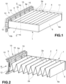
- Fig. 1 and 2 show a filtering element 1 comprising a zigzag-folded filtering web 2.
- the filtering element 1 is substantially slab-shaped and also comprises two opposing sides or lateral strips 3 and 4 which are made from the same material as the filtering web 2 and joined thereto.
- the material of the filtering element may comprise, for example, a non-woven fabric, and may comprise a single layer or a plurality of layers coupled to one another.
- the filtering web 2 comprises two end panels 5 and 6 which delimit the filtering web 2 in the longitudinal direction.
- longitudinal direction is understood to mean the direction orthogonal to the fold lines 2a of the filtering web 2.
- Each end panel 5, 6 ends with a free edge 5a, 6a which extends, according to a plan view, approximately parallel to the fold lines 2a.
- a cover 10 is shown which is configured to be removably fixed to a filter housing 11 adapted to receive the filtering element 1, which housing is only shown schematically by a dashed line in Fig. 1 .
- the cover 10 may be an element formed as a single piece of plastics material.
- a seal (not shown) may conventionally be provided on the cover 10, in order to sealingly close the cover 10 on a mouth of the filter housing 11.
- the cover 10 may conventionally be provided with fixing means, for example snap-fit coupling members 10a or holes 10b for screws, which are provided in order to fix the cover 10 at the mouth of the filter housing 11.
- the filter housing 11 may be a frame or a box, for example, and is designed to allow a flow of fluid, for example air, to pass through the filtering element 1 in a direction approximately orthogonal to the fold lines 2a.
- the cover 10 comprises a wall 12 which is adapted to be placed in front of and in contact with one of the end panels 5 of the filtering element 1.
- At least one holding formation 15 is formed on this wall 12, which formation is adapted to be coupled to the end panel 5 of the filtering element 1 in order to hold the filtering element 1 against the wall 12 of the cover 10.
- One particular holding formation will be described in the following, but it is understood that the invention is not limited thereto.
- the cover may not have a holding formation for holding the filtering element.
- the holding formations 15 are preferably formed as a single piece with the wall 12 of the cover 10. According to alternative embodiments that are less preferable, the holding formations may be pieces that are produced separately from the cover 10 and then permanently fixed thereto, for example glued or welded thereto.
- each holding formation 15 defines a slot 16 positioned between the wall 12 of the cover 10 and the holding formation 15, which slot is adapted to receive the end panel 5 of the filtering element 1.
- each holding formation 15 comprises a foot 17 which projects from the wall 12 and a holding arm 18 which extends from the foot 17 in a main direction that is approximately parallel to the wall 12.
- Each holding formation 15 is formed as an elastically deformable clip that is configured to exert an elastic holding force on the end panel 5 of the filtering element 1.
- the slot 16 has to have a minimum width d that is less than the thickness D of the end panel 5 of the filtering element 1.
- the cover 10 is shown in a simplified manner.
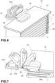
- An inspection hole 20 is formed on the wall 12 of the cover 10, which inspection hole passes through the wall 12 and is intended to allow the presence of the filtering element 1 to be detected.
- the cover 10 also comprises a plug 21 for closing the inspection hole 20.
- the plug 21 is formed as a single piece of plastics material with the wall 12 of the cover 10, for example by means of molding.
- the plug 21 is preferably connected to the wall 12 of the cover 10 by means of a living hinge 22.
- the plug 21 is shown both in a closed position in which it closes the inspection hole 20 and in various open positions allowed by the living hinge 22. In general, it is preferable for the plug 21 to remain connected to the wall 12 of the cover 10 even when the plug is in an open position, so as to allow easy handling of the component.
- the plug 21 closes onto the inspection hole 20 in a snap-fit manner, as a result of the presence of teeth 21a which engage the edge 20a of the inspection hole 20.
- the plug 21 is left open until the operation to check the presence of the filtering element 1 has been completed. Once this operation has been finished successfully, the plug 21 is closed.
Landscapes
- Chemical & Material Sciences (AREA)
- Chemical Kinetics & Catalysis (AREA)
- Filtering Of Dispersed Particles In Gases (AREA)
- Piezo-Electric Or Mechanical Vibrators, Or Delay Or Filter Circuits (AREA)
Description
- This invention relates to an assembly including
- a filtering element comprising a zigzag-folded filtering web that ends at the front with an end panel, and
- a cover configured to be removably fixed to a filter housing adapted to receive the filtering element, said cover comprising a wall adapted to be placed in front of and in contact with the end panel of the filtering element.
- Filtering elements which are formed by a zigzag-folded filtering web and made in particular of non-woven fabric are produced for a wide range of applications. For example, these filtering elements are used to filter fresh air for the cabin of motor vehicles or in air conditioning systems for rooms. In motor vehicles, filtering elements of this type are inserted into housings such as frames or boxes.
- One known problem relates to the difficulty in understanding whether the filtering element is present in an air conditioning unit after the compartment containing it has been inserted and closed. In fact, in some situations, the filtering element may be missing after the cover of the filter compartment has been closed, as a result of assembly workers missing out the required operation.
- Once closed by its cover, the compartment in which the air filter is intended to be contained is completely sealed, and it is no longer possible to inspect said compartment except by removing the cover.
-
KR 200342474 Y1 claim 1. - The object of this invention is to provide a solution that solves the disadvantages described above.
- In view of this object, the invention relates to an assembly having the features defined in
claim 1. In particular, an inspection hole is formed on the wall of the cover to allow the presence of the filtering element to be detected, the cover further comprising a plug for closing the inspection hole. - In a production line, by means of the assembly according to the invention, it will be easier to detect the presence of the contained filtering element once the cover that closes the filter compartment has been shut. By using, for example, a presence sensor or detector, it is thus possible to confirm that the filtering element is correctly installed, and authorize the assembly line to advance to the next station. In this case, the inspection hole is closed by the relevant plug.
- The invention completely eliminates, with certainty, all of the cases where, at the end of the assembly line or after the product has been sold to the client, it has not been promptly identified that there is no filtering element in the air conditioning unit, which would subsequently result in rework at the end of the line or even damage to the final product if it has been sold.
- The invention is therefore effective in monitoring and detecting human error in the assembly of an automotive component that is difficult to assemble in an automated manner, such as an air filter. This is because otherwise it would not be possible to verify the presence of a particular component that is not visible after assembly.
- Further features and advantages of the assembly according to the invention will become clearer from the following detailed description of an embodiment of the invention, made with reference to the accompanying drawings, provided purely for illustrative and non-limiting purposes, in which:
-
Fig. 1 is a perspective view of an assembly comprising a cover assembled to a filtering element; -
Fig. 2 is a cut-away view of the assembly inFig. 1 , taken along the line II-II; -
Fig. 3 is an enlarged view of a detail inFig. 2 that is shown by the arrow III; -
Fig. 4 is a plan view of the cover; -
Fig. 5 is a sectional view of the cover inFig. 4 , taken along the line V-V; -
Fig. 6 is a further perspective view of the assembly comprising a cover assembled to a filtering element; and -
Fig. 7 is a sectional view of the assembly inFig. 6 . -
Fig. 1 and 2 show afiltering element 1 comprising a zigzag-folded filteringweb 2. Thefiltering element 1 is substantially slab-shaped and also comprises two opposing sides orlateral strips web 2 and joined thereto. The material of the filtering element may comprise, for example, a non-woven fabric, and may comprise a single layer or a plurality of layers coupled to one another. - At its opposite ends, the
filtering web 2 comprises twoend panels web 2 in the longitudinal direction. For the purposes of this description, "longitudinal direction" is understood to mean the direction orthogonal to thefold lines 2a of the filteringweb 2. Eachend panel free edge fold lines 2a. - With reference also to
Fig. 3 to 5 , acover 10 is shown which is configured to be removably fixed to afilter housing 11 adapted to receive thefiltering element 1, which housing is only shown schematically by a dashed line inFig. 1 . - The
cover 10 may be an element formed as a single piece of plastics material. A seal (not shown) may conventionally be provided on thecover 10, in order to sealingly close thecover 10 on a mouth of thefilter housing 11. Moreover, thecover 10 may conventionally be provided with fixing means, for example snap-fit coupling members 10a orholes 10b for screws, which are provided in order to fix thecover 10 at the mouth of thefilter housing 11. Thefilter housing 11 may be a frame or a box, for example, and is designed to allow a flow of fluid, for example air, to pass through thefiltering element 1 in a direction approximately orthogonal to thefold lines 2a. - The
cover 10 comprises awall 12 which is adapted to be placed in front of and in contact with one of theend panels 5 of thefiltering element 1. At least one holding formation 15 (in the example, a plurality of holding formations) is formed on thiswall 12, which formation is adapted to be coupled to theend panel 5 of thefiltering element 1 in order to hold thefiltering element 1 against thewall 12 of thecover 10. One particular holding formation will be described in the following, but it is understood that the invention is not limited thereto. According to one embodiment, the cover may not have a holding formation for holding the filtering element. - The
holding formations 15 are preferably formed as a single piece with thewall 12 of thecover 10. According to alternative embodiments that are less preferable, the holding formations may be pieces that are produced separately from thecover 10 and then permanently fixed thereto, for example glued or welded thereto. - With particular reference to
Fig. 3 and 5 , eachholding formation 15 defines aslot 16 positioned between thewall 12 of thecover 10 and theholding formation 15, which slot is adapted to receive theend panel 5 of thefiltering element 1. In the example shown, eachholding formation 15 comprises afoot 17 which projects from thewall 12 and aholding arm 18 which extends from thefoot 17 in a main direction that is approximately parallel to thewall 12. - Each
holding formation 15 is formed as an elastically deformable clip that is configured to exert an elastic holding force on theend panel 5 of thefiltering element 1. For this purpose, theslot 16 has to have a minimum width d that is less than the thickness D of theend panel 5 of thefiltering element 1. - With reference to
Fig. 6 and 7 , thecover 10 is shown in a simplified manner. Aninspection hole 20 is formed on thewall 12 of thecover 10, which inspection hole passes through thewall 12 and is intended to allow the presence of thefiltering element 1 to be detected. Thecover 10 also comprises aplug 21 for closing theinspection hole 20. Theplug 21 is formed as a single piece of plastics material with thewall 12 of thecover 10, for example by means of molding. Theplug 21 is preferably connected to thewall 12 of thecover 10 by means of aliving hinge 22. InFig. 6 and 7 , theplug 21 is shown both in a closed position in which it closes theinspection hole 20 and in various open positions allowed by theliving hinge 22. In general, it is preferable for theplug 21 to remain connected to thewall 12 of thecover 10 even when the plug is in an open position, so as to allow easy handling of the component. - In the example shown, in the closed position, the
plug 21 closes onto theinspection hole 20 in a snap-fit manner, as a result of the presence ofteeth 21a which engage theedge 20a of theinspection hole 20. - In an assembly line, the
plug 21 is left open until the operation to check the presence of thefiltering element 1 has been completed. Once this operation has been finished successfully, theplug 21 is closed. - It is understood that the invention is not limited to the embodiments described and shown here, but instead may be subject to modifications relating to the shape and arrangement of parts and design and operating details, according to the numerous possible variants that will appear appropriate to those skilled in the art, and which are to be understood as included within the scope of the invention, as defined by the following claims.
Claims (5)
- An assembly includinga filtering element (1) anda cover (10) configured to be removably fixed to a filter housing (11) adapted to receive the filtering element (1), said cover comprising a wall (12),wherein an inspection hole (20) is formed on said wall (12) to allow the presence of the filtering element (1) to be detected, the cover (10) further comprising a plug (21) for closing the inspection hole (20),the assembly being characterized in that the filtering element (1) comprises a zigzag folded filtering web (2) that ends at the front with an end panel (5), wherein the wall (12) of the cover (10) is adapted to be placed in front of and in contact with the end panel (5) of the filtering element (1), and wherein the plug (21) is formed as a single piece of plastics material with the wall (12) of the cover (10).
- The assembly according to claim 1, wherein the plug (21) is connected to the wall (12) of the cover (10) by means of a living hinge (22).
- The assembly according to any of the preceding claims, wherein at least one holding formation (15) is formed on said wall (12), which formation is adapted to be coupled to the end panel (5) of the filtering element (1) to hold the filtering element (1) against the wall (12) of the cover (10).
- The assembly according to claim 3, wherein said at least one holding formation (15) defines a slot (16) positioned between the wall (12) of the cover (10) and the holding formation (15),wherein the slot (16) is adapted to receive a free edge (5a) of the end panel (5) of the filtering element (1), the slot (16) having a minimum width (d) less than the thickness (D) of the end panel (5) of the filtering element (1),wherein said at least one holding formation (15) is formed as an elastically deformable clip configured to exert an elastic holding force on the end panel (5) of the filtering element (1).
- The assembly according to claim 4, wherein said at least one holding formation (15) is formed as a single piece of plastics material with the wall (12) of the cover (10).
Applications Claiming Priority (1)
| Application Number | Priority Date | Filing Date | Title |
|---|---|---|---|
| IT102021000017729A IT202100017729A1 (en) | 2021-07-06 | 2021-07-06 | Group including a filter element and a lid provided with an inspection hole |
Publications (2)
| Publication Number | Publication Date |
|---|---|
| EP4115968A1 EP4115968A1 (en) | 2023-01-11 |
| EP4115968B1 true EP4115968B1 (en) | 2024-01-31 |
Family
ID=77989904
Family Applications (1)
| Application Number | Title | Priority Date | Filing Date |
|---|---|---|---|
| EP22181744.8A Active EP4115968B1 (en) | 2021-07-06 | 2022-06-29 | An assembly including a filtering element and a cover provided with an inspection hole |
Country Status (4)
| Country | Link |
|---|---|
| EP (1) | EP4115968B1 (en) |
| ES (1) | ES2973305T3 (en) |
| IT (1) | IT202100017729A1 (en) |
| MA (1) | MA60139B1 (en) |
Family Cites Families (4)
| Publication number | Priority date | Publication date | Assignee | Title |
|---|---|---|---|---|
| KR200342474Y1 (en) * | 1998-12-31 | 2004-06-02 | 한라공조주식회사 | Air Conditioning Unit Air Filter Cover |
| DE102008013501B4 (en) * | 2008-03-10 | 2014-02-20 | Carl Freudenberg Kg | Injection molded filter element for insertion into a filter housing |
| DE202008010474U1 (en) * | 2008-08-06 | 2009-12-17 | Mann+Hummel Gmbh | filter system |
| IT201800009906A1 (en) * | 2018-10-30 | 2020-04-30 | Denso Thermal Systems Spa | Cover for filter element. |
-
2021
- 2021-07-06 IT IT102021000017729A patent/IT202100017729A1/en unknown
-
2022
- 2022-06-29 EP EP22181744.8A patent/EP4115968B1/en active Active
- 2022-06-29 MA MA60139A patent/MA60139B1/en unknown
- 2022-06-29 ES ES22181744T patent/ES2973305T3/en active Active
Also Published As
| Publication number | Publication date |
|---|---|
| EP4115968A1 (en) | 2023-01-11 |
| ES2973305T3 (en) | 2024-06-19 |
| IT202100017729A1 (en) | 2023-01-06 |
| MA60139B1 (en) | 2024-02-29 |
Similar Documents
| Publication | Publication Date | Title |
|---|---|---|
| US10960735B2 (en) | Cabin air filter and filter assembly | |
| RU2656753C2 (en) | Air filter for vehicle ventilation system | |
| KR102423166B1 (en) | Air filter cartridge and air cleaner assembly | |
| US9126131B2 (en) | Air filter for a ventilation system of a motor vehicle | |
| CZ95094A3 (en) | Filter element and process for producing thereof | |
| JP2009511332A5 (en) | ||
| KR100670469B1 (en) | Filter element | |
| EP0951335B1 (en) | Air filter | |
| CN106457110B (en) | Fluid filtration system | |
| CZ299328B6 (en) | Filter system | |
| US9233332B2 (en) | Air filter assembly filling plenum interior space | |
| AU2018225103B2 (en) | Filter with shield features | |
| EP4115968A1 (en) | An assembly including a filtering element and a cover provided with an inspection hole | |
| EP2072106A1 (en) | Air-filter assembly for vehicles | |
| CN106999827B (en) | Flat filter elements and filter units | |
| US10974188B2 (en) | Filter with shield features | |
| KR102011729B1 (en) | Air conditioner for vehicle | |
| KR100650240B1 (en) | Arrangement for a plate-type filter element in a gas filter housing | |
| EP2319602B1 (en) | Filter assembly for a vehicle heating or air conditioning system, filter unit for this purpose and method for the production of the filter assembly. | |
| CN118076498A (en) | Filter device, vehicle, use and method | |
| BR0311174B1 (en) | cassette filter for gas purification. | |
| EP3646933B1 (en) | A cover for filtering element | |
| US20100263542A1 (en) | Frame flange attachable to a filter cartridge to form a filter assembly | |
| JP7041591B2 (en) | Air filter device | |
| US12208662B2 (en) | Housing for a heating, air-conditioning and/or ventilation device for a motor vehicle |
Legal Events
| Date | Code | Title | Description |
|---|---|---|---|
| PUAI | Public reference made under article 153(3) epc to a published international application that has entered the european phase |
Free format text: ORIGINAL CODE: 0009012 |
|
| STAA | Information on the status of an ep patent application or granted ep patent |
Free format text: STATUS: THE APPLICATION HAS BEEN PUBLISHED |
|
| AK | Designated contracting states |
Kind code of ref document: A1 Designated state(s): AL AT BE BG CH CY CZ DE DK EE ES FI FR GB GR HR HU IE IS IT LI LT LU LV MC MK MT NL NO PL PT RO RS SE SI SK SM TR |
|
| STAA | Information on the status of an ep patent application or granted ep patent |
Free format text: STATUS: REQUEST FOR EXAMINATION WAS MADE |
|
| 17P | Request for examination filed |
Effective date: 20230329 |
|
| RAV | Requested validation state of the european patent: fee paid |
Extension state: MA Effective date: 20230329 |
|
| RBV | Designated contracting states (corrected) |
Designated state(s): AL AT BE BG CH CY CZ DE DK EE ES FI FR GB GR HR HU IE IS IT LI LT LU LV MC MK MT NL NO PL PT RO RS SE SI SK SM TR |
|
| GRAP | Despatch of communication of intention to grant a patent |
Free format text: ORIGINAL CODE: EPIDOSNIGR1 |
|
| STAA | Information on the status of an ep patent application or granted ep patent |
Free format text: STATUS: GRANT OF PATENT IS INTENDED |
|
| INTG | Intention to grant announced |
Effective date: 20230901 |
|
| GRAS | Grant fee paid |
Free format text: ORIGINAL CODE: EPIDOSNIGR3 |
|
| GRAA | (expected) grant |
Free format text: ORIGINAL CODE: 0009210 |
|
| STAA | Information on the status of an ep patent application or granted ep patent |
Free format text: STATUS: THE PATENT HAS BEEN GRANTED |
|
| AK | Designated contracting states |
Kind code of ref document: B1 Designated state(s): AL AT BE BG CH CY CZ DE DK EE ES FI FR GB GR HR HU IE IS IT LI LT LU LV MC MK MT NL NO PL PT RO RS SE SI SK SM TR |
|
| REG | Reference to a national code |
Ref country code: GB Ref legal event code: FG4D Ref country code: CH Ref legal event code: EP |
|
| REG | Reference to a national code |
Ref country code: DE Ref legal event code: R096 Ref document number: 602022001771 Country of ref document: DE |
|
| REG | Reference to a national code |
Ref country code: IE Ref legal event code: FG4D |
|
| REG | Reference to a national code |
Ref country code: MA Ref legal event code: VAGR Ref document number: 60139 Country of ref document: MA Kind code of ref document: B1 |
|
| REG | Reference to a national code |
Ref country code: LT Ref legal event code: MG9D |
|
| REG | Reference to a national code |
Ref country code: NL Ref legal event code: MP Effective date: 20240131 |
|
| REG | Reference to a national code |
Ref country code: ES Ref legal event code: FG2A Ref document number: 2973305 Country of ref document: ES Kind code of ref document: T3 Effective date: 20240619 |
|
| PG25 | Lapsed in a contracting state [announced via postgrant information from national office to epo] |
Ref country code: IS Free format text: LAPSE BECAUSE OF FAILURE TO SUBMIT A TRANSLATION OF THE DESCRIPTION OR TO PAY THE FEE WITHIN THE PRESCRIBED TIME-LIMIT Effective date: 20240531 |
|
| PG25 | Lapsed in a contracting state [announced via postgrant information from national office to epo] |
Ref country code: LT Free format text: LAPSE BECAUSE OF FAILURE TO SUBMIT A TRANSLATION OF THE DESCRIPTION OR TO PAY THE FEE WITHIN THE PRESCRIBED TIME-LIMIT Effective date: 20240131 |
|
| PG25 | Lapsed in a contracting state [announced via postgrant information from national office to epo] |
Ref country code: GR Free format text: LAPSE BECAUSE OF FAILURE TO SUBMIT A TRANSLATION OF THE DESCRIPTION OR TO PAY THE FEE WITHIN THE PRESCRIBED TIME-LIMIT Effective date: 20240501 |
|
| REG | Reference to a national code |
Ref country code: AT Ref legal event code: MK05 Ref document number: 1653478 Country of ref document: AT Kind code of ref document: T Effective date: 20240131 |
|
| PG25 | Lapsed in a contracting state [announced via postgrant information from national office to epo] |
Ref country code: RS Free format text: LAPSE BECAUSE OF FAILURE TO SUBMIT A TRANSLATION OF THE DESCRIPTION OR TO PAY THE FEE WITHIN THE PRESCRIBED TIME-LIMIT Effective date: 20240430 Ref country code: NL Free format text: LAPSE BECAUSE OF FAILURE TO SUBMIT A TRANSLATION OF THE DESCRIPTION OR TO PAY THE FEE WITHIN THE PRESCRIBED TIME-LIMIT Effective date: 20240131 Ref country code: HR Free format text: LAPSE BECAUSE OF FAILURE TO SUBMIT A TRANSLATION OF THE DESCRIPTION OR TO PAY THE FEE WITHIN THE PRESCRIBED TIME-LIMIT Effective date: 20240131 |
|
| PG25 | Lapsed in a contracting state [announced via postgrant information from national office to epo] |
Ref country code: AT Free format text: LAPSE BECAUSE OF FAILURE TO SUBMIT A TRANSLATION OF THE DESCRIPTION OR TO PAY THE FEE WITHIN THE PRESCRIBED TIME-LIMIT Effective date: 20240131 |
|
| PG25 | Lapsed in a contracting state [announced via postgrant information from national office to epo] |
Ref country code: RS Free format text: LAPSE BECAUSE OF FAILURE TO SUBMIT A TRANSLATION OF THE DESCRIPTION OR TO PAY THE FEE WITHIN THE PRESCRIBED TIME-LIMIT Effective date: 20240430 Ref country code: NO Free format text: LAPSE BECAUSE OF FAILURE TO SUBMIT A TRANSLATION OF THE DESCRIPTION OR TO PAY THE FEE WITHIN THE PRESCRIBED TIME-LIMIT Effective date: 20240430 Ref country code: NL Free format text: LAPSE BECAUSE OF FAILURE TO SUBMIT A TRANSLATION OF THE DESCRIPTION OR TO PAY THE FEE WITHIN THE PRESCRIBED TIME-LIMIT Effective date: 20240131 Ref country code: LT Free format text: LAPSE BECAUSE OF FAILURE TO SUBMIT A TRANSLATION OF THE DESCRIPTION OR TO PAY THE FEE WITHIN THE PRESCRIBED TIME-LIMIT Effective date: 20240131 Ref country code: IS Free format text: LAPSE BECAUSE OF FAILURE TO SUBMIT A TRANSLATION OF THE DESCRIPTION OR TO PAY THE FEE WITHIN THE PRESCRIBED TIME-LIMIT Effective date: 20240531 Ref country code: HR Free format text: LAPSE BECAUSE OF FAILURE TO SUBMIT A TRANSLATION OF THE DESCRIPTION OR TO PAY THE FEE WITHIN THE PRESCRIBED TIME-LIMIT Effective date: 20240131 Ref country code: GR Free format text: LAPSE BECAUSE OF FAILURE TO SUBMIT A TRANSLATION OF THE DESCRIPTION OR TO PAY THE FEE WITHIN THE PRESCRIBED TIME-LIMIT Effective date: 20240501 Ref country code: FI Free format text: LAPSE BECAUSE OF FAILURE TO SUBMIT A TRANSLATION OF THE DESCRIPTION OR TO PAY THE FEE WITHIN THE PRESCRIBED TIME-LIMIT Effective date: 20240131 Ref country code: BG Free format text: LAPSE BECAUSE OF FAILURE TO SUBMIT A TRANSLATION OF THE DESCRIPTION OR TO PAY THE FEE WITHIN THE PRESCRIBED TIME-LIMIT Effective date: 20240131 Ref country code: AT Free format text: LAPSE BECAUSE OF FAILURE TO SUBMIT A TRANSLATION OF THE DESCRIPTION OR TO PAY THE FEE WITHIN THE PRESCRIBED TIME-LIMIT Effective date: 20240131 |
|
| PG25 | Lapsed in a contracting state [announced via postgrant information from national office to epo] |
Ref country code: PT Free format text: LAPSE BECAUSE OF FAILURE TO SUBMIT A TRANSLATION OF THE DESCRIPTION OR TO PAY THE FEE WITHIN THE PRESCRIBED TIME-LIMIT Effective date: 20240531 Ref country code: PL Free format text: LAPSE BECAUSE OF FAILURE TO SUBMIT A TRANSLATION OF THE DESCRIPTION OR TO PAY THE FEE WITHIN THE PRESCRIBED TIME-LIMIT Effective date: 20240131 |
|
| PG25 | Lapsed in a contracting state [announced via postgrant information from national office to epo] |
Ref country code: SE Free format text: LAPSE BECAUSE OF FAILURE TO SUBMIT A TRANSLATION OF THE DESCRIPTION OR TO PAY THE FEE WITHIN THE PRESCRIBED TIME-LIMIT Effective date: 20240131 Ref country code: PT Free format text: LAPSE BECAUSE OF FAILURE TO SUBMIT A TRANSLATION OF THE DESCRIPTION OR TO PAY THE FEE WITHIN THE PRESCRIBED TIME-LIMIT Effective date: 20240531 Ref country code: PL Free format text: LAPSE BECAUSE OF FAILURE TO SUBMIT A TRANSLATION OF THE DESCRIPTION OR TO PAY THE FEE WITHIN THE PRESCRIBED TIME-LIMIT Effective date: 20240131 Ref country code: LV Free format text: LAPSE BECAUSE OF FAILURE TO SUBMIT A TRANSLATION OF THE DESCRIPTION OR TO PAY THE FEE WITHIN THE PRESCRIBED TIME-LIMIT Effective date: 20240131 |
|
| PG25 | Lapsed in a contracting state [announced via postgrant information from national office to epo] |
Ref country code: DK Free format text: LAPSE BECAUSE OF FAILURE TO SUBMIT A TRANSLATION OF THE DESCRIPTION OR TO PAY THE FEE WITHIN THE PRESCRIBED TIME-LIMIT Effective date: 20240131 |
|
| PG25 | Lapsed in a contracting state [announced via postgrant information from national office to epo] |
Ref country code: SM Free format text: LAPSE BECAUSE OF FAILURE TO SUBMIT A TRANSLATION OF THE DESCRIPTION OR TO PAY THE FEE WITHIN THE PRESCRIBED TIME-LIMIT Effective date: 20240131 |
|
| PG25 | Lapsed in a contracting state [announced via postgrant information from national office to epo] |
Ref country code: EE Free format text: LAPSE BECAUSE OF FAILURE TO SUBMIT A TRANSLATION OF THE DESCRIPTION OR TO PAY THE FEE WITHIN THE PRESCRIBED TIME-LIMIT Effective date: 20240131 Ref country code: CZ Free format text: LAPSE BECAUSE OF FAILURE TO SUBMIT A TRANSLATION OF THE DESCRIPTION OR TO PAY THE FEE WITHIN THE PRESCRIBED TIME-LIMIT Effective date: 20240131 |
|
| PG25 | Lapsed in a contracting state [announced via postgrant information from national office to epo] |
Ref country code: SK Free format text: LAPSE BECAUSE OF FAILURE TO SUBMIT A TRANSLATION OF THE DESCRIPTION OR TO PAY THE FEE WITHIN THE PRESCRIBED TIME-LIMIT Effective date: 20240131 |
|
| PG25 | Lapsed in a contracting state [announced via postgrant information from national office to epo] |
Ref country code: SM Free format text: LAPSE BECAUSE OF FAILURE TO SUBMIT A TRANSLATION OF THE DESCRIPTION OR TO PAY THE FEE WITHIN THE PRESCRIBED TIME-LIMIT Effective date: 20240131 Ref country code: SK Free format text: LAPSE BECAUSE OF FAILURE TO SUBMIT A TRANSLATION OF THE DESCRIPTION OR TO PAY THE FEE WITHIN THE PRESCRIBED TIME-LIMIT Effective date: 20240131 Ref country code: EE Free format text: LAPSE BECAUSE OF FAILURE TO SUBMIT A TRANSLATION OF THE DESCRIPTION OR TO PAY THE FEE WITHIN THE PRESCRIBED TIME-LIMIT Effective date: 20240131 Ref country code: DK Free format text: LAPSE BECAUSE OF FAILURE TO SUBMIT A TRANSLATION OF THE DESCRIPTION OR TO PAY THE FEE WITHIN THE PRESCRIBED TIME-LIMIT Effective date: 20240131 Ref country code: CZ Free format text: LAPSE BECAUSE OF FAILURE TO SUBMIT A TRANSLATION OF THE DESCRIPTION OR TO PAY THE FEE WITHIN THE PRESCRIBED TIME-LIMIT Effective date: 20240131 |
|
| REG | Reference to a national code |
Ref country code: DE Ref legal event code: R097 Ref document number: 602022001771 Country of ref document: DE |
|
| PG25 | Lapsed in a contracting state [announced via postgrant information from national office to epo] |
Ref country code: IT Free format text: LAPSE BECAUSE OF FAILURE TO SUBMIT A TRANSLATION OF THE DESCRIPTION OR TO PAY THE FEE WITHIN THE PRESCRIBED TIME-LIMIT Effective date: 20240131 |
|
| PLBE | No opposition filed within time limit |
Free format text: ORIGINAL CODE: 0009261 |
|
| STAA | Information on the status of an ep patent application or granted ep patent |
Free format text: STATUS: NO OPPOSITION FILED WITHIN TIME LIMIT |
|
| PG25 | Lapsed in a contracting state [announced via postgrant information from national office to epo] |
Ref country code: IT Free format text: LAPSE BECAUSE OF FAILURE TO SUBMIT A TRANSLATION OF THE DESCRIPTION OR TO PAY THE FEE WITHIN THE PRESCRIBED TIME-LIMIT Effective date: 20240131 |
|
| 26N | No opposition filed |
Effective date: 20241101 |
|
| PG25 | Lapsed in a contracting state [announced via postgrant information from national office to epo] |
Ref country code: MC Free format text: LAPSE BECAUSE OF FAILURE TO SUBMIT A TRANSLATION OF THE DESCRIPTION OR TO PAY THE FEE WITHIN THE PRESCRIBED TIME-LIMIT Effective date: 20240131 |
|
| PG25 | Lapsed in a contracting state [announced via postgrant information from national office to epo] |
Ref country code: LU Free format text: LAPSE BECAUSE OF NON-PAYMENT OF DUE FEES Effective date: 20240629 |
|
| PG25 | Lapsed in a contracting state [announced via postgrant information from national office to epo] |
Ref country code: IE Free format text: LAPSE BECAUSE OF NON-PAYMENT OF DUE FEES Effective date: 20240629 |
|
| PG25 | Lapsed in a contracting state [announced via postgrant information from national office to epo] |
Ref country code: SI Free format text: LAPSE BECAUSE OF FAILURE TO SUBMIT A TRANSLATION OF THE DESCRIPTION OR TO PAY THE FEE WITHIN THE PRESCRIBED TIME-LIMIT Effective date: 20240131 Ref country code: BE Free format text: LAPSE BECAUSE OF NON-PAYMENT OF DUE FEES Effective date: 20240630 |
|
| REG | Reference to a national code |
Ref country code: BE Ref legal event code: MM Effective date: 20240630 |
|
| PGFP | Annual fee paid to national office [announced via postgrant information from national office to epo] |
Ref country code: DE Payment date: 20250624 Year of fee payment: 4 |
|
| PGFP | Annual fee paid to national office [announced via postgrant information from national office to epo] |
Ref country code: FR Payment date: 20250530 Year of fee payment: 4 |
|
| PGFP | Annual fee paid to national office [announced via postgrant information from national office to epo] |
Ref country code: RO Payment date: 20250522 Year of fee payment: 4 |
|
| PGFP | Annual fee paid to national office [announced via postgrant information from national office to epo] |
Ref country code: ES Payment date: 20250701 Year of fee payment: 4 |
|
| VSFP | Annual fee paid to validation state [announced via postgrant information from national office to epo] |
Ref country code: MA Payment date: 20240628 Year of fee payment: 3 |
|
| PG25 | Lapsed in a contracting state [announced via postgrant information from national office to epo] |
Ref country code: CY Free format text: LAPSE BECAUSE OF FAILURE TO SUBMIT A TRANSLATION OF THE DESCRIPTION OR TO PAY THE FEE WITHIN THE PRESCRIBED TIME-LIMIT; INVALID AB INITIO Effective date: 20220629 |
|
| VSFP | Annual fee paid to validation state [announced via postgrant information from national office to epo] |
Ref country code: MA Payment date: 20250623 Year of fee payment: 4 |
|
| REG | Reference to a national code |
Ref country code: CH Ref legal event code: H13 Free format text: ST27 STATUS EVENT CODE: U-0-0-H10-H13 (AS PROVIDED BY THE NATIONAL OFFICE) Effective date: 20260127 |
|
| PG25 | Lapsed in a contracting state [announced via postgrant information from national office to epo] |
Ref country code: HU Free format text: LAPSE BECAUSE OF FAILURE TO SUBMIT A TRANSLATION OF THE DESCRIPTION OR TO PAY THE FEE WITHIN THE PRESCRIBED TIME-LIMIT; INVALID AB INITIO Effective date: 20220629 |
|
| PG25 | Lapsed in a contracting state [announced via postgrant information from national office to epo] |
Ref country code: CH Free format text: LAPSE BECAUSE OF NON-PAYMENT OF DUE FEES Effective date: 20250630 |