EP4115925A1 - Syringe assembly and drug solution administration device - Google Patents
Syringe assembly and drug solution administration device Download PDFInfo
- Publication number
- EP4115925A1 EP4115925A1 EP21771625.7A EP21771625A EP4115925A1 EP 4115925 A1 EP4115925 A1 EP 4115925A1 EP 21771625 A EP21771625 A EP 21771625A EP 4115925 A1 EP4115925 A1 EP 4115925A1
- Authority
- EP
- European Patent Office
- Prior art keywords
- distal
- seal member
- pressing
- cap
- syringe
- Prior art date
- Legal status (The legal status is an assumption and is not a legal conclusion. Google has not performed a legal analysis and makes no representation as to the accuracy of the status listed.)
- Granted
Links
Images





Classifications
-
- A—HUMAN NECESSITIES
- A61—MEDICAL OR VETERINARY SCIENCE; HYGIENE
- A61M—DEVICES FOR INTRODUCING MEDIA INTO, OR ONTO, THE BODY; DEVICES FOR TRANSDUCING BODY MEDIA OR FOR TAKING MEDIA FROM THE BODY; DEVICES FOR PRODUCING OR ENDING SLEEP OR STUPOR
- A61M5/00—Devices for bringing media into the body in a subcutaneous, intra-vascular or intramuscular way; Accessories therefor, e.g. filling or cleaning devices, arm-rests
- A61M5/178—Syringes
- A61M5/31—Details
- A61M5/3129—Syringe barrels
- A61M5/3134—Syringe barrels characterised by constructional features of the distal end, i.e. end closest to the tip of the needle cannula
-
- A—HUMAN NECESSITIES
- A61—MEDICAL OR VETERINARY SCIENCE; HYGIENE
- A61M—DEVICES FOR INTRODUCING MEDIA INTO, OR ONTO, THE BODY; DEVICES FOR TRANSDUCING BODY MEDIA OR FOR TAKING MEDIA FROM THE BODY; DEVICES FOR PRODUCING OR ENDING SLEEP OR STUPOR
- A61M5/00—Devices for bringing media into the body in a subcutaneous, intra-vascular or intramuscular way; Accessories therefor, e.g. filling or cleaning devices, arm-rests
- A61M5/178—Syringes
- A61M5/24—Ampoule syringes, i.e. syringes with needle for use in combination with replaceable ampoules or carpules, e.g. automatic
- A61M5/2455—Ampoule syringes, i.e. syringes with needle for use in combination with replaceable ampoules or carpules, e.g. automatic with sealing means to be broken or opened
- A61M5/2466—Ampoule syringes, i.e. syringes with needle for use in combination with replaceable ampoules or carpules, e.g. automatic with sealing means to be broken or opened by piercing without internal pressure increase
-
- A—HUMAN NECESSITIES
- A61—MEDICAL OR VETERINARY SCIENCE; HYGIENE
- A61M—DEVICES FOR INTRODUCING MEDIA INTO, OR ONTO, THE BODY; DEVICES FOR TRANSDUCING BODY MEDIA OR FOR TAKING MEDIA FROM THE BODY; DEVICES FOR PRODUCING OR ENDING SLEEP OR STUPOR
- A61M5/00—Devices for bringing media into the body in a subcutaneous, intra-vascular or intramuscular way; Accessories therefor, e.g. filling or cleaning devices, arm-rests
- A61M5/178—Syringes
- A61M5/28—Syringe ampoules or carpules, i.e. ampoules or carpules provided with a needle
- A61M5/285—Syringe ampoules or carpules, i.e. ampoules or carpules provided with a needle with sealing means to be broken or opened
-
- A—HUMAN NECESSITIES
- A61—MEDICAL OR VETERINARY SCIENCE; HYGIENE
- A61M—DEVICES FOR INTRODUCING MEDIA INTO, OR ONTO, THE BODY; DEVICES FOR TRANSDUCING BODY MEDIA OR FOR TAKING MEDIA FROM THE BODY; DEVICES FOR PRODUCING OR ENDING SLEEP OR STUPOR
- A61M5/00—Devices for bringing media into the body in a subcutaneous, intra-vascular or intramuscular way; Accessories therefor, e.g. filling or cleaning devices, arm-rests
- A61M5/178—Syringes
- A61M5/31—Details
- A61M2005/3103—Leak prevention means for distal end of syringes, i.e. syringe end for mounting a needle
- A61M2005/3104—Caps for syringes without needle
-
- A—HUMAN NECESSITIES
- A61—MEDICAL OR VETERINARY SCIENCE; HYGIENE
- A61M—DEVICES FOR INTRODUCING MEDIA INTO, OR ONTO, THE BODY; DEVICES FOR TRANSDUCING BODY MEDIA OR FOR TAKING MEDIA FROM THE BODY; DEVICES FOR PRODUCING OR ENDING SLEEP OR STUPOR
- A61M5/00—Devices for bringing media into the body in a subcutaneous, intra-vascular or intramuscular way; Accessories therefor, e.g. filling or cleaning devices, arm-rests
- A61M5/178—Syringes
- A61M5/31—Details
- A61M2005/3103—Leak prevention means for distal end of syringes, i.e. syringe end for mounting a needle
- A61M2005/3106—Plugs for syringes without needle
Definitions
- the present invention relates to a syringe assembly sealing a liquid medicine and a liquid-medicine administration device.
- the liquid-medicine administration device includes a syringe assembly filled with a liquid medicine.
- a syringe assembly includes a syringe having a distal nozzle portion, a cap fixed to the distal nozzle portion, and a seal member arranged between the cap and the distal nozzle portion and made of an elastic body that seals an opening of the distal nozzle portion.
- a step of aligning an axis of the cap and an axis of the syringe coaxially and fitting the cap toward the distal nozzle portion is performed by a mounting device. Meanwhile, it has been found that the axis of the cap is sometimes inclined with respect to the axis of the syringe when the cap is assembled, a crushing load on the seal member by the distal nozzle portion varies to cause a variation in the pressure limit.
- an object of one embodiment is to provide a syringe assembly and a liquid-medicine administration device capable of suppressing a variation in a pressure limit of a seal member.
- An aspect of the following disclosure relates to a syringe assembly including: a syringe having a distal nozzle portion; a cap fixed to the distal nozzle portion; and a seal member arranged between the cap and the distal nozzle portion and made of an elastic body that seals the distal nozzle portion, the cap having a pressing surface that is in surface contact with a distal end of the seal member and presses the seal member to a proximal side, the distal nozzle portion having a sealing surface, which opposes the pressing surface and is in surface contact with a proximal end of the seal member, at a distal end and a distal opening which is formed on an inner peripheral side of the sealing surface and communicates with a lumen of the syringe, the seal member closing the distal opening and being pressed and held in an axial direction in a pressing space over a whole region of an opposing portion between the pressing surface and the sealing surface, and a gap between the pressing surface and the sealing surface in the pressing space being
- Another aspect relates to a liquid-medicine administration device including: the syringe assembly according to the above aspect; a gasket arranged to be slidable inside the syringe; a plunger assembly capable of pressing the gasket in a distal direction, and a drive mechanism driving the plunger assembly.
- the crushing load on the seal member by the distal nozzle portion is made uniform, and the variation in the pressure limit is suppressed.
- the liquid-medicine administration device 10 illustrated in Fig. 1 is used to administer a liquid medicine M into a living body.
- the liquid-medicine administration device 10 continuously administers the liquid medicine M charged in the syringe assembly 12A into the living body under pressing action of a plunger assembly 14 for a relatively long time (for example, about several minutes to several hours).
- the liquid-medicine administration device 10 may intermittently administer the liquid medicine M into the living body.
- the liquid medicine M include a protein preparation, a narcotic analgesic, a diuretic, and the like.
- a patch-type needle-attached tube 17 is connected as an administration tool 16.
- the liquid medicine M discharged from the syringe assembly 12A is injected into the body of a patient via the needle-attached tube 17.
- the needle-attached tube 17 includes: a connector 18 that can be connected to a distal nozzle portion 56 of the syringe assembly 12A; a liquid supply tube 19 having one end connected to the connector 18 and having flexibility; a patch portion 20 that is connected to the other end of the liquid supply tube 19 and can be stuck to a skin S; and a puncture needle 21 protruding from the patch portion 20.
- the puncture needle 21 substantially perpendicularly punctures the skin S.
- the puncture needle 21 may be one that obliquely punctures the skin S.
- the liquid-medicine administration device 10 includes: the syringe assembly 12A having a syringe 24 filled with the liquid medicine M; a gasket 26 arranged to be slidable inside the syringe 24; the plunger assembly 14 that is stretchable in the axial direction (arrow X direction) and can press the gasket 26 in the distal direction (arrow X1 direction); a drive mechanism 28 that drives the plunger assembly 14; a battery 30 that supplies electric power necessary for the operation of the liquid-medicine administration device 10; a control unit 32 that controls the drive mechanism 28; a chassis structure 34 that supports the syringe assembly 12A, the plunger assembly 14, and the drive mechanism 28; and a housing 36 that houses these.
- the syringe assembly 12A includes: the syringe 24 having the distal nozzle portion 56; a cap 44 mounted on the distal nozzle portion 56 of the syringe 24; and a seal member 46 arranged between the distal nozzle portion 56 and the cap 44.
- the syringe 24 is formed in a hollow cylindrical shape. Specifically, the syringe 24 includes a barrel portion 50 having a lumen 13 that can be filled with the liquid medicine M, and a flange portion 54 protruding outward from an outer peripheral surface of the barrel portion 50. The inside of the syringe 24 is filled with the liquid medicine M in advance.
- the syringe 24 may be made of a transparent material.
- a distal portion of the distal nozzle portion 56 is provided with an engagement projecting portion 56a.
- the engagement projecting portion 56a is formed in an annular shape that protrudes radially outward and extends to make a round in the circumferential direction.
- the engagement projecting portion 56a includes: a locking surface 56a1 on which claw portions 74a and 74b, which will be described later, of the cap 44 are locked; and an inclined surface 56a2 which is formed on the distal side of the locking surface 56a1 and reduced in diameter in the distal direction.
- the locking surface 56a1 is a flat surface perpendicular to an axis of the distal nozzle portion 56.
- an annular groove 56b that is recessed radially inward is formed on the proximal side of the engagement projecting portion 56a.
- An anti-rattling projecting portion 56e that prevents rattling of the cap 44 is provided on the outer periphery of a proximal portion of the distal nozzle portion 56.
- the anti-rattling projecting portion 56e is formed in an annular shape that bulges radially outward and extends to make a round in the circumferential direction.
- An outer peripheral surface of the anti-rattling projecting portion 56e extends along the axis of the distal nozzle portion 56.
- a proximal end of the anti-rattling projecting portion 56e is connected to a distal end of the shoulder portion 52.
- a sealing surface 60 perpendicular to the axial direction is formed at a distal end of the distal nozzle portion 56.
- the sealing surface 60 is formed in a circular ring shape on the outer peripheral side of a distal opening 58. Since the substantially entire radial region of the sealing surface 60 is in surface contact with the seal member 46, high sealing performance (pressure resistance) is exhibited, and liquid leakage can be prevented even if a relatively high pressure of the lumen 13 acts.
- the sealing surface 60 can have an inner diameter set to about 0.5 to 5.0 mm, and an outer diameter set to about 2.0 to 9.0 mm.
- a ring-shaped protrusion 62 protruding toward the axially distal side (a pressing surface 48) is formed on the inner peripheral side of the sealing surface 60.
- the ring-shaped protrusion 62 is formed in an annular shape along an inner peripheral portion of the sealing surface 60.
- a protruding height of the ring-shaped protrusion 62 is formed to such an extent as not to hinder the surface contact between an outer peripheral portion 46d of the seal member 46 and the sealing surface 60.
- the ring-shaped protrusion 62 prevents movement of a wall of the seal member 46 from moving when the cap 44 is mounted.
- a protruding height in the axial direction can be set to about 0.05 to 1.5 mm and a dimension in the radial direction (width direction) can be set to about 0.05 to 1.5 mm.
- the seal member 46 is punctured by a needle 18a provided in the connector 18 when the connector 18 illustrated in Fig. 1 is connected to the distal nozzle portion 56.
- the seal member 46 is made of an elastic resin material such as a rubber material or an elastomer material formed in a plate shape.
- the seal member 46 is fixed to the distal nozzle portion 56 of the syringe assembly 12A by the cap 44 to seal the distal opening 58 of the distal nozzle portion 56.
- the seal member 46 is held in a state of being elastically compressed in the axial direction between the sealing surface 60 of the distal nozzle portion 56 and the pressing surface 48 of the cap 44.
- the seal member 46 is formed in a disc shape.
- the seal member 46 includes: a seal body portion 46a forming a central portion in the thickness direction; a distal projecting portion 46b protruding in the distal direction from the distal side of the seal body portion 46a; and a proximal projecting portion 46c protruding in the proximal direction from the proximal side of the seal body portion 46a.
- the distal projecting portion 46b slightly protrudes in the distal direction from the pressing surface 48 of the cap 44.
- a surface on the distal side of the distal projecting portion 46b may be located at the same axial position as the pressing surface 48 of the cap 44 or on the proximal side of the pressing surface 48.
- the outer peripheral portion 46d of the distal projecting portion 46b and a proximal projecting portion 46c of the seal member 46 is arranged in a pressing space 64 formed between the sealing surface 60 of the distal nozzle portion 56 and the pressing surface 48 of the cap 44.
- a proximal end of the outer peripheral portion 46d of the seal member 46 is in surface contact and close contact with substantially the entire radial region of the sealing surface 60, thereby exhibiting the pressure resistance.
- the outer peripheral portion 46d of the seal member 46 is in surface contact with the pressing surface 48 of the cap 44 on the distal side. Then, the outer peripheral portion 46d is pressed in the axial direction by the pressing surface 48 and the sealing surface 60.
- the pressing space 64 is a space between the sealing surface 60 of the distal nozzle portion 56 and the pressing surface 48 of the cap 44 at a portion opposing the sealing surface, and is formed in a circular ring shape on the outer peripheral side of the distal opening 58 of the distal nozzle portion 56. Since the ring-shaped protrusion 62 is formed along the inner peripheral side of the sealing surface 60 in the present embodiment, a width D1 on the inner peripheral side is narrower than a width D2 on the outer peripheral side regarding a width D (gap) of the pressing space 64 in the axial direction. That is, the width D of the pressing space 64 in the axial direction is narrowest on the inner peripheral side.
- the cap 44 includes a base portion 66 provided on the distal side of the cap 44, and a mounting portion 72 which has a cylindrical shape, extends from the base portion 66 in the proximal direction along an axis of the cap 44, and covers the outside of the distal nozzle portion 56.
- the pressing surface 48 that is in surface contact with the seal member 46 is formed on the proximal side of the base portion 66.
- the pressing surface 48 is formed in a circular ring shape around a through-hole 70 at the center.
- the through-hole 70 is formed in a central portion of the base portion 66 to penetrate the base portion in the axial direction and expose the distal projecting portion 46b of the seal member 46.
- the through-hole 70 is a hole formed in a circular shape when viewed from the axial direction, and is formed coaxially with the cap 44.
- the through-hole 70 is formed in a distal wall 68 of the base portion 66.
- the distal projecting portion 46b of the seal member 46 is inserted into the through-hole 70.
- the mounting portion 72 includes claw portions 74a and 74b, a first column portion 76, and a second column portion 78.
- the two claw portions 74a and 74b oppose each other across the central axis of the cap 44, and are formed at positions spaced apart from the base portion 66 to the proximal side.
- the claw portions 74a and 74b protrude inward from an inner peripheral surface of the mounting portion 72.
- the cap 44 is mounted to the distal nozzle portion 56 as the two claw portions 74a and 74b engage with the engagement projecting portion 56a of the distal nozzle portion 56.
- each of the two claw portions 74a and 74b engages with the proximal end (locking surface 56a1) of the engagement projecting portion 56a of the distal nozzle portion 56, thereby preventing the cap 44 from coming off from the distal nozzle portion 56.
- Each of the two claw portions 74a and 74b extends in an arc shape in the circumferential direction along the inner peripheral surface of the mounting portion 72.
- the first column portion 76 is provided on the outer side of one claw portion 74a in the circumferential direction of the mounting portion 72, and extends to the proximal side along the axis of the cap 44.
- the second column portion 78 is provided on the outer side of the other claw portion 74b in the circumferential direction of the mounting portion 72, and extends to the proximal side along the axis of the cap 44. Inner peripheral surfaces of the first column portion 76 and the second column portion 78 abut on the anti-rattling projecting portion 56e of the distal nozzle portion 56, thereby preventing the cap 44 from being inclined with respect to the distal nozzle portion 56.
- the first column portion 76 and the second column portion 78 are integrally connected to the base portion 66 via the side wall portion 80.
- Two side holes 82 are formed on the distal side of the side wall portion 80. The side holes 82 penetrate the side wall portion 80 in the radial direction.
- the gasket 26 liquid-tightly seals the proximal side of the lumen 13 of the syringe 24.
- the gasket 26 is located on the distal side of a proximal end of the syringe 24.
- An outer portion of the gasket 26 is in close contact with an inner peripheral surface of the syringe 24 (barrel portion 50) in a liquid-tight manner.
- the syringe assembly 12A, the liquid medicine M, and the gasket 26 form a prefilled syringe 15.
- the plunger assembly 14 is configured to advance the gasket 26 inside the syringe 24 and push out the liquid medicine M from the syringe assembly 12A.
- the drive mechanism 28 includes: a motor 31 which is driven and controlled under control of the control unit 32 using the battery 30 as a power source; and a drive gear 37 fixed to an output shaft of the motor 31.
- the chassis structure 34 is arranged inside the housing 36 (see Fig. 1 ).
- the syringe assembly 12A, the drive mechanism 28, and the plunger assembly 14 are fixed to predetermined positions of the chassis structure 34, respectively.
- the chassis structure 34 includes a chassis body member 34a and a motor holding member 34b that is fixed to the chassis body member 34a and holds the motor 31 against the chassis body member 34a.
- the chassis body member 34a has a flange holding portion 34c that protrudes upward and holds the flange portion 54 of the syringe 24.
- the flange holding portion 34c is provided with a holding groove 34d into which the flange portion 54 is inserted.
- the housing 36 is a hollow member configured to house the syringe assembly 12A, the gasket 26, the plunger assembly 14, the drive mechanism 28, the battery 30, the control unit 32, and the chassis structure 34 described above.
- the distal nozzle portion 56 of the syringe assembly 12A protrudes from the housing 36, and the cap 44 is exposed to the outside.
- a window portion 36w made of a transparent material is provided on an upper surface 36a of the housing 36.
- the liquid-medicine administration device 10 can be configured as a patch type that is used by being stuck to the skin S of the patient, for example.
- a sheet-shaped sticking portion (adhesive portion) that can be stuck to the skin S is provided on a bottom surface 36b of the housing 36.
- a peelable protective sheet is stuck to a sticking surface of the sticking portion.
- the liquid-medicine administration device 10 is provided with a mounting tool, such as a hook and a clip, on the bottom surface 36b of the housing 36 and mounted by a method of being hooked on clothes of the patient (for example, a waist portion of pants or the like).
- a mounting tool such as a hook and a clip
- a syringe preparation step In the assembly step of the syringe assembly 12A, a syringe preparation step, a seal member preparation step, a cap preparation step, a cap assembly step, and a cap mounting step (see Fig. 5 ) are sequentially performed.
- the syringe 24 including the distal nozzle portion 56 having the engagement projecting portion 56a provided on the outer peripheral surface and the distal opening 58 is prepared.
- the plate-shaped seal member 46 having elasticity is prepared.
- the cap 44 including the base portion 66, made of a hard resin material and provided at the distal end, and the cylindrical mounting portion 72, which extends from the base portion 66 in the proximal direction along the axis of the cap 44, is prepared.
- the seal member 46 is inserted into the inner peripheral side of the mounting portion 72 of the cap 44, and the seal member 46 is in surface contact with the pressing surface 48.
- the distal projecting portion 46b of the seal member 46 is inserted into the through-hole 70.
- the distal nozzle portion 56 is inserted into the mounting portion 72 of the cap 44 to which the seal member 46 is attached. Then, the cap 44 is pushed to the proximal side until the two claw portions 74a and 74b of the mounting portion 72 pass over the engagement projecting portion 56a of the distal nozzle portion 56. Then, the distal opening 58 of the distal nozzle portion 56 is sealed with the seal member 46.
- the cap mounting step is performed by press-fitting the cap 44 toward the distal nozzle portion 56 while gripping the cap 44 and the syringe 24 with a chuck of the mounting device.
- the inner peripheral surface of the mounting portion 72 of the cap 44 abuts on the anti-rattling projecting portion 56e of the distal nozzle portion 56, and the cap 44 is assembled without being inclined.
- the cap 44 may be inclined with respect to the distal nozzle portion 56 as illustrated in Figs. 4 and 5 due to various factors.
- a seal member 46 is in surface contact with a pressing surface 48 of the cap 44 and the sealing surface 160 of the distal nozzle portion 156 to form a pressing space 164.
- the pressing space 164 has a shape that is open in a V shape so as to gradually expand toward the inner peripheral side as a width D1 in the axial direction on the inner peripheral side becomes larger than a width D2 in the axial direction on the outer peripheral side. Therefore, in the process of pushing the cap 44 to the proximal side, a wall of the seal member 46 moves so as to escape from the pressing space 164 toward a non-pressed site.
- a compressive load on the sealing surface 160 varies in the circumferential direction of the seal member 46, and a pressure limit decreases. That is, in the seal member 46, a wall thickness of a portion that first abuts on the sealing surface 160 is insufficient, and the sealing performance between the sealing surface 160 and the seal member 46 deteriorates in the state after the cap 44 is mounted.
- the ring-shaped protrusion 62 is formed on the inner peripheral portion of the sealing surface 60 of the distal nozzle portion 56 as illustrated in Fig. 5 .
- the seal member 46 is in surface contact with the pressing surface 48 of the cap 44 and the sealing surface 60 of the distal nozzle portion 56 to form the pressing space 64.
- the ring-shaped protrusion 62 is provided as illustrated in the drawing, the width D1 in the axial direction on the inner peripheral side of the pressing space 64 is smaller than the width D2 in the axial direction on the outer peripheral side thereof, and the width D1 in the axial direction of the inner peripheral portion of the pressing space 64 is the narrowest.
- the movement of the wall of the seal member 46 is prevented.
- a compressive load on the sealing surface 60 becomes uniform in the circumferential direction of the seal member 46, and the pressure limit can be improved.
- Fig. 6 illustrates measurement results of Experimental Example 1.
- the vertical axis represents the test force (N)
- the horizontal axis represents the displacement (mm) of the test plunger.
- the test force reflects the internal pressure of a syringe 24 and increases as the displacement of the test plunger increases. When liquid leakage occurs, the test force does not increase and becomes constant even if the displacement of the test plunger increases. Therefore, the maximum value of the test force reflects the pressure limit by the seal member 46 in Fig. 6 .
- the maximum value of the test force ranges from 80 to 200 N with a relatively large variation.
- the pressure limit was an extremely low value between 80 and 120 N.
- the syringe assembly 12A and the liquid-medicine administration device 10 of the present embodiment have the following effects.
- the syringe assembly 12A of the present embodiment includes the syringe 24 having the distal nozzle portion 56, the cap 44 fixed to the distal nozzle portion 56, and the seal member 46 arranged between the cap 44 and the distal nozzle portion 56 and made of the elastic body that seals the distal nozzle portion 56.
- the cap 44 has the pressing surface 48 that is in surface contact with the distal end of the seal member 46 and presses the seal member 46 to the proximal side
- the distal nozzle portion 56 has the sealing surface 60, which opposes the pressing surface 48 and is in surface contact with the proximal end of the seal member 46, at the distal end and the distal opening 58 which is formed on the inner peripheral side of the sealing surface 60 and communicates with the lumen 13 of the syringe 24, the seal member 46 closes the distal opening 58 and is pressed and held in the axial direction in the pressing space 64 over a whole region of the opposing portion between the pressing surface 48 and the sealing surface 60, and the gap between the pressing surface 48 and the sealing surface 60 in the pressing space 64 is narrowest on the inner peripheral side.
- the sealing surface 60 may be provided with the ring-shaped protrusion 62 which is formed in the annular shape along the inner peripheral side and protrudes toward the pressing surface 48. Since the ring-shaped protrusion 62 is provided on the inner peripheral side in this manner, the gap between the pressing surface 48 and the sealing surface 60 in the pressing space 64 can be made narrowest on the inner peripheral side, and the movement of the wall of the seal member 46 can be prevented.
- the liquid-medicine administration device 10 of the present embodiment includes: the syringe assembly 12A that includes the syringe 24 having the distal nozzle portion 56, the cap 44 fixed to the distal nozzle portion 56; the seal member 46 arranged between the cap 44 and the distal nozzle portion 56 and made of the elastic body that seals the distal nozzle portion 56, and the cap 44 having the pressing surface 48 that is in surface contact with the distal end of the seal member 46 and presses the seal member 46 to the proximal side, the distal nozzle portion 56 having the sealing surface 60, which opposes the pressing surface 48 and is in surface contact with the proximal end of the seal member 46, at the distal end and the distal opening 58 which is formed on the inner peripheral side of the sealing surface 60 and communicates with the lumen 13 of the syringe 24, the seal member 46 closing the distal opening 58 and being pressed and held in the axial direction in the pressing space 64 over the whole region of the opposing portion between the pressing surface 48 and the sealing surface
- the liquid-medicine administration device 10 having the above configuration, the variation in the pressure limit of the seal member 46 is suppressed, and thus, the liquid leakage hardly occurs.
- the syringe assembly 12B of the present embodiment is configured such that a sealing surface 60B of the distal nozzle portion 56 is an inclined surface inclined with respect to the pressing surface 48 of the cap 44.
- the inner peripheral side adjacent to the distal opening 58 protrudes toward the pressing surface 48 the most. That is, the sealing surface 60B is configured as the inclined surface inclined so as to gradually protrude toward the pressing surface 48 from the outer peripheral side to the inner peripheral side.
- a width D1 in the axial direction on the inner peripheral side of a pressing space 64B, which presses the outer peripheral portion 46d of the seal member 46 in the axial direction is the narrowest even in the syringe assembly 12B.
- the syringe assembly 12B of the present embodiment has the following effects.
- the sealing surface 60B is configured as the inclined surface inclined so as to gradually protrude toward the pressing surface from the outer peripheral side to the inner peripheral side.
- the syringe assembly 12C of the present embodiment is provided with a ring-shaped protrusion 62C, which protrudes toward the sealing surface 60 of the distal nozzle portion 56, in an inner peripheral portion of a pressing surface 48C of the cap 44.
- the ring-shaped protrusion 62C is formed in an annular shape along the through-hole 70 of the cap 44.
- a ring-shaped groove 46e is formed in a portion corresponding to the ring-shaped protrusion 62C, and the ring-shaped protrusion 62C is inserted into the ring-shaped groove 46e.
- the sealing surface 60 of the distal nozzle portion 56 is formed as a flat surface perpendicular to the axial direction.
- the ring-shaped protrusion 62 (see Fig. 3 ) is not formed on the sealing surface 60 in the illustrated example, the present invention is not limited thereto, and the ring-shaped protrusion 62 may be formed on the inner peripheral side of the sealing surface 60.
- a width D1 in the axial direction on the inner peripheral side of a pressing space 64C is the narrowest in the pressing space 64C that presses the seal member 46.
- the syringe assembly 12C of the present embodiment has the following effects.
- the pressing surface 48C is provided with the ring-shaped protrusion 62C which is formed in the annular shape along the inner peripheral side and protrudes toward the sealing surface 60.
- the syringe assembly 12D of the present embodiment is configured such that a pressing surface 48D of the cap 44 is an inclined surface inclined with respect to the sealing surface 60 of the distal nozzle portion 56.
- the pressing surface 48D protrudes toward the sealing surface 60 the most on the inner peripheral side adjacent to the through-hole 70. That is, the pressing surface 48D is configured as the inclined surface inclined so as to gradually protrude toward the sealing surface 60 from the outer peripheral side to the inner peripheral side.
- an upper end side of the outer peripheral portion 46d of the seal member 46 of the present embodiment is configured as an inclined surface corresponding to the inclination of the pressing surface 48D.
- the sealing surface 60 of the distal nozzle portion 56 is formed as a flat surface perpendicular to the axial direction.
- the ring-shaped protrusion 62 (see Fig. 3 ) is not formed on the sealing surface 60 in the illustrated example, the present invention is not limited thereto, and the ring-shaped protrusion 62 may be formed on the inner peripheral side of the sealing surface 60.
- a width D1 in the axial direction on the inner peripheral side of the pressing space 64D is the narrowest even when where the cap 44 is inclined, movement of a wall of the seal member 46 can be prevented in a cap mounting step as illustrated in Fig.13 .
- a pressing load in the circumferential direction of the seal member 46 is made uniform even by the present embodiment so that a variation in a pressure limit can be suppressed.
- the syringe assembly 12D of the present embodiment has the following effects.
- the pressing surface 48D is configured as the inclined surface inclined so as to gradually protrude toward the sealing surface 60 from the outer peripheral side to the inner peripheral side.
Landscapes
- Health & Medical Sciences (AREA)
- Vascular Medicine (AREA)
- Engineering & Computer Science (AREA)
- Anesthesiology (AREA)
- Biomedical Technology (AREA)
- Heart & Thoracic Surgery (AREA)
- Hematology (AREA)
- Life Sciences & Earth Sciences (AREA)
- Animal Behavior & Ethology (AREA)
- General Health & Medical Sciences (AREA)
- Public Health (AREA)
- Veterinary Medicine (AREA)
- Infusion, Injection, And Reservoir Apparatuses (AREA)
Abstract
Description
- The present invention relates to a syringe assembly sealing a liquid medicine and a liquid-medicine administration device.
- Conventionally, there is proposed a liquid-medicine administration device of a syringe pump type in which a liquid medicine charged in a cylindrical body is administered into a living body under pressing action of a plunger (
WO 2019/182031 A ). The liquid-medicine administration device includes a syringe assembly filled with a liquid medicine. A syringe assembly includes a syringe having a distal nozzle portion, a cap fixed to the distal nozzle portion, and a seal member arranged between the cap and the distal nozzle portion and made of an elastic body that seals an opening of the distal nozzle portion. - In an assembly step of the syringe assembly, there is a problem that the compression of the seal member becomes non-uniform in the circumferential direction, an internal pressure (pressure limit) at which liquid leakage occurs varies, and the syringe assembly having an extremely low pressure limit is formed.
- In the cap, a step of aligning an axis of the cap and an axis of the syringe coaxially and fitting the cap toward the distal nozzle portion is performed by a mounting device. Meanwhile, it has been found that the axis of the cap is sometimes inclined with respect to the axis of the syringe when the cap is assembled, a crushing load on the seal member by the distal nozzle portion varies to cause a variation in the pressure limit.
- Therefore, an object of one embodiment is to provide a syringe assembly and a liquid-medicine administration device capable of suppressing a variation in a pressure limit of a seal member.
- An aspect of the following disclosure relates to a syringe assembly including: a syringe having a distal nozzle portion; a cap fixed to the distal nozzle portion; and a seal member arranged between the cap and the distal nozzle portion and made of an elastic body that seals the distal nozzle portion, the cap having a pressing surface that is in surface contact with a distal end of the seal member and presses the seal member to a proximal side, the distal nozzle portion having a sealing surface, which opposes the pressing surface and is in surface contact with a proximal end of the seal member, at a distal end and a distal opening which is formed on an inner peripheral side of the sealing surface and communicates with a lumen of the syringe, the seal member closing the distal opening and being pressed and held in an axial direction in a pressing space over a whole region of an opposing portion between the pressing surface and the sealing surface, and a gap between the pressing surface and the sealing surface in the pressing space being narrowest on an inner peripheral side.
- Another aspect relates to a liquid-medicine administration device including: the syringe assembly according to the above aspect; a gasket arranged to be slidable inside the syringe; a plunger assembly capable of pressing the gasket in a distal direction, and a drive mechanism driving the plunger assembly.
- According to the syringe assembly and the liquid-medicine administration device of the above aspects, the crushing load on the seal member by the distal nozzle portion is made uniform, and the variation in the pressure limit is suppressed.
-
-
Fig. 1 is a schematic diagram of a liquid-medicine administration device including a syringe assembly according to a first embodiment. -
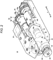
Fig. 2 is a perspective view of the liquid-medicine administration device ofFig. 1 from which a housing has been removed. -
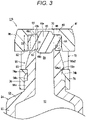
Fig. 3 is a cross-sectional view of the distal side of the syringe assembly ofFig. 2 . -
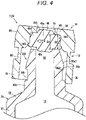
Fig. 4 is a cross-sectional view of the distal side of a syringe assembly according to a comparative example. -
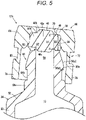
Fig. 5 is a cross-sectional view illustrating action of the syringe assembly ofFig. 3 . -
Fig. 6 is a graph illustrating a measurement result of a pressure limit of the syringe assembly according to Experimental Example 1 (the comparative example). -
Fig. 7 is a graph illustrating a measurement result of a pressure limit of the syringe assembly according to Experimental Example 2 (the first embodiment). -
Fig. 8 is a cross-sectional view of the distal side of a syringe assembly according to a second embodiment. -
Fig. 9 is a cross-sectional view illustrating action of the syringe assembly ofFig. 8 . -
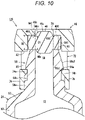
Fig. 10 is a cross-sectional view of a distal side of a syringe assembly according to a third embodiment. -
Fig. 11 is a cross-sectional view illustrating action of the syringe assembly ofFig. 10 . -
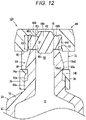
Fig. 12 is a cross-sectional view of a distal side of a syringe assembly according to a fourth embodiment. -
Fig. 13 is a cross-sectional view illustrating action of the syringe assembly ofFig. 12 . - Hereinafter, preferred embodiments regarding
syringe assemblies medicine administration device 10 will be described in detail with reference to the accompanying drawings. Incidentally, only the main parts will be illustrated in second to fourth embodiments, and the same or similar configurations as those of the first embodiment will be denoted by the same reference signs, and the detailed description thereof will be omitted. - The liquid-
medicine administration device 10 illustrated inFig. 1 is used to administer a liquid medicine M into a living body. The liquid-medicine administration device 10 continuously administers the liquid medicine M charged in thesyringe assembly 12A into the living body under pressing action of aplunger assembly 14 for a relatively long time (for example, about several minutes to several hours). The liquid-medicine administration device 10 may intermittently administer the liquid medicine M into the living body. Examples of the liquid medicine M include a protein preparation, a narcotic analgesic, a diuretic, and the like. - As illustrated in
Fig. 1 , when the liquid-medicine administration device 10 is used, for example, a patch-type needle-attachedtube 17 is connected as anadministration tool 16. The liquid medicine M discharged from thesyringe assembly 12A is injected into the body of a patient via the needle-attachedtube 17. The needle-attachedtube 17 includes: aconnector 18 that can be connected to adistal nozzle portion 56 of thesyringe assembly 12A; aliquid supply tube 19 having one end connected to theconnector 18 and having flexibility; apatch portion 20 that is connected to the other end of theliquid supply tube 19 and can be stuck to a skin S; and apuncture needle 21 protruding from thepatch portion 20. Thepuncture needle 21 substantially perpendicularly punctures the skin S. Incidentally, thepuncture needle 21 may be one that obliquely punctures the skin S. - As illustrated in
Fig. 1 or2 , the liquid-medicine administration device 10 includes: thesyringe assembly 12A having asyringe 24 filled with the liquid medicine M; agasket 26 arranged to be slidable inside thesyringe 24; theplunger assembly 14 that is stretchable in the axial direction (arrow X direction) and can press thegasket 26 in the distal direction (arrow X1 direction); adrive mechanism 28 that drives theplunger assembly 14; abattery 30 that supplies electric power necessary for the operation of the liquid-medicine administration device 10; acontrol unit 32 that controls thedrive mechanism 28; achassis structure 34 that supports thesyringe assembly 12A, theplunger assembly 14, and thedrive mechanism 28; and ahousing 36 that houses these. - As illustrated in
Fig. 2 , thesyringe assembly 12A includes: thesyringe 24 having thedistal nozzle portion 56; acap 44 mounted on thedistal nozzle portion 56 of thesyringe 24; and aseal member 46 arranged between thedistal nozzle portion 56 and thecap 44. - The
syringe 24 is formed in a hollow cylindrical shape. Specifically, thesyringe 24 includes abarrel portion 50 having alumen 13 that can be filled with the liquid medicine M, and aflange portion 54 protruding outward from an outer peripheral surface of thebarrel portion 50. The inside of thesyringe 24 is filled with the liquid medicine M in advance. Thesyringe 24 may be made of a transparent material. - As illustrated in
Fig. 3 , a distal portion of thedistal nozzle portion 56 is provided with anengagement projecting portion 56a. Theengagement projecting portion 56a is formed in an annular shape that protrudes radially outward and extends to make a round in the circumferential direction. Theengagement projecting portion 56a includes: a locking surface 56a1 on whichclaw portions cap 44 are locked; and an inclined surface 56a2 which is formed on the distal side of the locking surface 56a1 and reduced in diameter in the distal direction. The locking surface 56a1 is a flat surface perpendicular to an axis of thedistal nozzle portion 56. On an outer peripheral surface of thedistal nozzle portion 56, anannular groove 56b that is recessed radially inward is formed on the proximal side of theengagement projecting portion 56a. - An
anti-rattling projecting portion 56e that prevents rattling of thecap 44 is provided on the outer periphery of a proximal portion of thedistal nozzle portion 56. Theanti-rattling projecting portion 56e is formed in an annular shape that bulges radially outward and extends to make a round in the circumferential direction. An outer peripheral surface of theanti-rattling projecting portion 56e extends along the axis of thedistal nozzle portion 56. A proximal end of theanti-rattling projecting portion 56e is connected to a distal end of theshoulder portion 52. - A sealing
surface 60 perpendicular to the axial direction is formed at a distal end of thedistal nozzle portion 56. The sealingsurface 60 is formed in a circular ring shape on the outer peripheral side of adistal opening 58. Since the substantially entire radial region of thesealing surface 60 is in surface contact with theseal member 46, high sealing performance (pressure resistance) is exhibited, and liquid leakage can be prevented even if a relatively high pressure of thelumen 13 acts. The sealingsurface 60 can have an inner diameter set to about 0.5 to 5.0 mm, and an outer diameter set to about 2.0 to 9.0 mm. - A ring-
shaped protrusion 62 protruding toward the axially distal side (a pressing surface 48) is formed on the inner peripheral side of thesealing surface 60. The ring-shaped protrusion 62 is formed in an annular shape along an inner peripheral portion of thesealing surface 60. A protruding height of the ring-shaped protrusion 62 is formed to such an extent as not to hinder the surface contact between an outerperipheral portion 46d of theseal member 46 and thesealing surface 60. The ring-shaped protrusion 62 prevents movement of a wall of theseal member 46 from moving when thecap 44 is mounted. As dimensions of the ring-shaped protrusion 62 exhibiting such a function, for example, a protruding height in the axial direction can be set to about 0.05 to 1.5 mm and a dimension in the radial direction (width direction) can be set to about 0.05 to 1.5 mm. - The
seal member 46 is punctured by aneedle 18a provided in theconnector 18 when theconnector 18 illustrated inFig. 1 is connected to thedistal nozzle portion 56. Theseal member 46 is made of an elastic resin material such as a rubber material or an elastomer material formed in a plate shape. Theseal member 46 is fixed to thedistal nozzle portion 56 of thesyringe assembly 12A by thecap 44 to seal thedistal opening 58 of thedistal nozzle portion 56. Theseal member 46 is held in a state of being elastically compressed in the axial direction between the sealingsurface 60 of thedistal nozzle portion 56 and thepressing surface 48 of thecap 44. Theseal member 46 is formed in a disc shape. - The
seal member 46 includes: aseal body portion 46a forming a central portion in the thickness direction; a distal projectingportion 46b protruding in the distal direction from the distal side of theseal body portion 46a; and a proximal projectingportion 46c protruding in the proximal direction from the proximal side of theseal body portion 46a. The distal projectingportion 46b slightly protrudes in the distal direction from thepressing surface 48 of thecap 44. A surface on the distal side of the distal projectingportion 46b may be located at the same axial position as thepressing surface 48 of thecap 44 or on the proximal side of thepressing surface 48. - The outer
peripheral portion 46d of the distal projectingportion 46b and a proximal projectingportion 46c of theseal member 46 is arranged in apressing space 64 formed between the sealingsurface 60 of thedistal nozzle portion 56 and thepressing surface 48 of thecap 44. In thepressing space 64, a proximal end of the outerperipheral portion 46d of theseal member 46 is in surface contact and close contact with substantially the entire radial region of the sealingsurface 60, thereby exhibiting the pressure resistance. In addition, the outerperipheral portion 46d of theseal member 46 is in surface contact with thepressing surface 48 of thecap 44 on the distal side. Then, the outerperipheral portion 46d is pressed in the axial direction by thepressing surface 48 and the sealingsurface 60. - The
pressing space 64 is a space between the sealingsurface 60 of thedistal nozzle portion 56 and thepressing surface 48 of thecap 44 at a portion opposing the sealing surface, and is formed in a circular ring shape on the outer peripheral side of thedistal opening 58 of thedistal nozzle portion 56. Since the ring-shapedprotrusion 62 is formed along the inner peripheral side of the sealingsurface 60 in the present embodiment, a width D1 on the inner peripheral side is narrower than a width D2 on the outer peripheral side regarding a width D (gap) of thepressing space 64 in the axial direction. That is, the width D of thepressing space 64 in the axial direction is narrowest on the inner peripheral side. - The
cap 44 includes abase portion 66 provided on the distal side of thecap 44, and a mountingportion 72 which has a cylindrical shape, extends from thebase portion 66 in the proximal direction along an axis of thecap 44, and covers the outside of thedistal nozzle portion 56. Thepressing surface 48 that is in surface contact with theseal member 46 is formed on the proximal side of thebase portion 66. Thepressing surface 48 is formed in a circular ring shape around a through-hole 70 at the center. The through-hole 70 is formed in a central portion of thebase portion 66 to penetrate the base portion in the axial direction and expose the distal projectingportion 46b of theseal member 46. - The through-
hole 70 is a hole formed in a circular shape when viewed from the axial direction, and is formed coaxially with thecap 44. The through-hole 70 is formed in adistal wall 68 of thebase portion 66. The distal projectingportion 46b of theseal member 46 is inserted into the through-hole 70. - The mounting
portion 72 includesclaw portions first column portion 76, and asecond column portion 78. The twoclaw portions cap 44, and are formed at positions spaced apart from thebase portion 66 to the proximal side. Theclaw portions portion 72. Thecap 44 is mounted to thedistal nozzle portion 56 as the twoclaw portions engagement projecting portion 56a of thedistal nozzle portion 56. That is, the twoclaw portions engagement projecting portion 56a of thedistal nozzle portion 56, thereby preventing thecap 44 from coming off from thedistal nozzle portion 56. Each of the twoclaw portions portion 72. - The
first column portion 76 is provided on the outer side of oneclaw portion 74a in the circumferential direction of the mountingportion 72, and extends to the proximal side along the axis of thecap 44. Thesecond column portion 78 is provided on the outer side of theother claw portion 74b in the circumferential direction of the mountingportion 72, and extends to the proximal side along the axis of thecap 44. Inner peripheral surfaces of thefirst column portion 76 and thesecond column portion 78 abut on theanti-rattling projecting portion 56e of thedistal nozzle portion 56, thereby preventing thecap 44 from being inclined with respect to thedistal nozzle portion 56. Thefirst column portion 76 and thesecond column portion 78 are integrally connected to thebase portion 66 via theside wall portion 80. Two side holes 82 are formed on the distal side of theside wall portion 80. The side holes 82 penetrate theside wall portion 80 in the radial direction. - In
Fig. 2 , thegasket 26 liquid-tightly seals the proximal side of thelumen 13 of thesyringe 24. In an initial state of the liquid-medicine administration device 10, thegasket 26 is located on the distal side of a proximal end of thesyringe 24. An outer portion of thegasket 26 is in close contact with an inner peripheral surface of the syringe 24 (barrel portion 50) in a liquid-tight manner. Thesyringe assembly 12A, the liquid medicine M, and thegasket 26 form aprefilled syringe 15. - The
plunger assembly 14 is configured to advance thegasket 26 inside thesyringe 24 and push out the liquid medicine M from thesyringe assembly 12A. In the initial state of the liquid-medicine administration device 10, the distal side of theplunger assembly 14 is inserted into the proximal side of thesyringe 24. Thedrive mechanism 28 includes: amotor 31 which is driven and controlled under control of thecontrol unit 32 using thebattery 30 as a power source; and adrive gear 37 fixed to an output shaft of themotor 31. - The
chassis structure 34 is arranged inside the housing 36 (seeFig. 1 ). Thesyringe assembly 12A, thedrive mechanism 28, and theplunger assembly 14 are fixed to predetermined positions of thechassis structure 34, respectively. Thechassis structure 34 includes achassis body member 34a and amotor holding member 34b that is fixed to thechassis body member 34a and holds themotor 31 against thechassis body member 34a. - The
chassis body member 34a has aflange holding portion 34c that protrudes upward and holds theflange portion 54 of thesyringe 24. Theflange holding portion 34c is provided with a holdinggroove 34d into which theflange portion 54 is inserted. - In
Fig. 1 , thehousing 36 is a hollow member configured to house thesyringe assembly 12A, thegasket 26, theplunger assembly 14, thedrive mechanism 28, thebattery 30, thecontrol unit 32, and thechassis structure 34 described above. Thedistal nozzle portion 56 of thesyringe assembly 12A protrudes from thehousing 36, and thecap 44 is exposed to the outside. Awindow portion 36w made of a transparent material is provided on anupper surface 36a of thehousing 36. - The liquid-
medicine administration device 10 can be configured as a patch type that is used by being stuck to the skin S of the patient, for example. In the case of such a patch type, a sheet-shaped sticking portion (adhesive portion) that can be stuck to the skin S is provided on abottom surface 36b of thehousing 36. In the initial state of the liquid-medicine administration device 10, a peelable protective sheet is stuck to a sticking surface of the sticking portion. - Incidentally, the liquid-
medicine administration device 10 is provided with a mounting tool, such as a hook and a clip, on thebottom surface 36b of thehousing 36 and mounted by a method of being hooked on clothes of the patient (for example, a waist portion of pants or the like). - Next, the action (assembly step) of the
syringe assembly 12A will be described with reference to a comparative example. - In the assembly step of the
syringe assembly 12A, a syringe preparation step, a seal member preparation step, a cap preparation step, a cap assembly step, and a cap mounting step (seeFig. 5 ) are sequentially performed. - In the syringe preparation step, the
syringe 24 including thedistal nozzle portion 56 having theengagement projecting portion 56a provided on the outer peripheral surface and thedistal opening 58 is prepared. - In the seal member preparation step, the plate-shaped
seal member 46 having elasticity is prepared. - In the cap preparation step, the
cap 44 including thebase portion 66, made of a hard resin material and provided at the distal end, and the cylindrical mountingportion 72, which extends from thebase portion 66 in the proximal direction along the axis of thecap 44, is prepared. - In the cap assembly step, the
seal member 46 is inserted into the inner peripheral side of the mountingportion 72 of thecap 44, and theseal member 46 is in surface contact with thepressing surface 48. In addition, the distal projectingportion 46b of theseal member 46 is inserted into the through-hole 70. - In the cap mounting step, the
distal nozzle portion 56 is inserted into the mountingportion 72 of thecap 44 to which theseal member 46 is attached. Then, thecap 44 is pushed to the proximal side until the twoclaw portions portion 72 pass over theengagement projecting portion 56a of thedistal nozzle portion 56. Then, thedistal opening 58 of thedistal nozzle portion 56 is sealed with theseal member 46. - The cap mounting step is performed by press-fitting the
cap 44 toward thedistal nozzle portion 56 while gripping thecap 44 and thesyringe 24 with a chuck of the mounting device. In a state inFig. 5 where the cap mounting step is completed, the inner peripheral surface of the mountingportion 72 of thecap 44 abuts on theanti-rattling projecting portion 56e of thedistal nozzle portion 56, and thecap 44 is assembled without being inclined. However, in the middle of pushing thecap 44 into thedistal nozzle portion 56, thecap 44 may be inclined with respect to thedistal nozzle portion 56 as illustrated inFigs. 4 and5 due to various factors. - As illustrated in
Fig. 4 , in asyringe assembly 112A of the comparative example, no ring-shapedprotrusion 62 is formed on a sealingsurface 160 of adistal nozzle portion 156. In the process of pushing acap 44, aseal member 46 is in surface contact with apressing surface 48 of thecap 44 and the sealingsurface 160 of thedistal nozzle portion 156 to form apressing space 164. When thecap 44 is inclined in the case of the comparative example, thepressing space 164 has a shape that is open in a V shape so as to gradually expand toward the inner peripheral side as a width D1 in the axial direction on the inner peripheral side becomes larger than a width D2 in the axial direction on the outer peripheral side. Therefore, in the process of pushing thecap 44 to the proximal side, a wall of theseal member 46 moves so as to escape from thepressing space 164 toward a non-pressed site. - As a result, a compressive load on the sealing
surface 160 varies in the circumferential direction of theseal member 46, and a pressure limit decreases. That is, in theseal member 46, a wall thickness of a portion that first abuts on the sealingsurface 160 is insufficient, and the sealing performance between the sealingsurface 160 and theseal member 46 deteriorates in the state after thecap 44 is mounted. - On the other hand, in the
syringe assembly 12A of the present embodiment, the ring-shapedprotrusion 62 is formed on the inner peripheral portion of the sealingsurface 60 of thedistal nozzle portion 56 as illustrated inFig. 5 . In the process of pushing thecap 44, theseal member 46 is in surface contact with thepressing surface 48 of thecap 44 and the sealingsurface 60 of thedistal nozzle portion 56 to form thepressing space 64. Since the ring-shapedprotrusion 62 is provided as illustrated in the drawing, the width D1 in the axial direction on the inner peripheral side of thepressing space 64 is smaller than the width D2 in the axial direction on the outer peripheral side thereof, and the width D1 in the axial direction of the inner peripheral portion of thepressing space 64 is the narrowest. As a result, the movement of the wall of theseal member 46 is prevented. As a result, a compressive load on the sealingsurface 60 becomes uniform in the circumferential direction of theseal member 46, and the pressure limit can be improved. - Next, a description will be given regarding results obtained by actually preparing the
syringe assembly 112A of the comparative example (Experimental Example 1) and thesyringe assembly 12A of the present embodiment (Experimental Example 2) and measuring a pressure limit at which liquid leakage occurs when thegasket 26 is pushed. - In Experimental Example 1, five samples in which water was sealed as a test liquid in the
syringe assembly 112A of Comparative Example 1 illustrated inFig. 4 were prepared. Then, agasket 26 was pushed by a test plunger, and a displacement (mm) of the test plunger and a test force (N), which is an input load with respect to the test plunger, were measured. -
Fig. 6 illustrates measurement results of Experimental Example 1. InFig. 6 , the vertical axis represents the test force (N), and the horizontal axis represents the displacement (mm) of the test plunger. The test force reflects the internal pressure of asyringe 24 and increases as the displacement of the test plunger increases. When liquid leakage occurs, the test force does not increase and becomes constant even if the displacement of the test plunger increases. Therefore, the maximum value of the test force reflects the pressure limit by theseal member 46 inFig. 6 . - As illustrated in the drawing, in Experimental Example 1, the maximum value of the test force ranges from 80 to 200 N with a relatively large variation. Regarding two samples, the pressure limit was an extremely low value between 80 and 120 N.
- On the other hand, in Experimental Example 2, five samples in which water was sealed in the
syringe assembly 12A of the present embodiment illustrated inFig. 3 were prepared, and the pressure limit was evaluated by the same method as in Experimental Example 1.Fig. 7 illustrates measurement results of Experimental Example 2. - As illustrated in
Fig. 7 , in Experimental Example 2 (the present embodiment), the maximum value of the test force fell within the range of 200 to 240 N, and it has been confirmed that a variation in the pressure limit was suppressed, and there is no sample having an extremely low pressure limit. - The
syringe assembly 12A and the liquid-medicine administration device 10 of the present embodiment have the following effects. - The
syringe assembly 12A of the present embodiment includes thesyringe 24 having thedistal nozzle portion 56, thecap 44 fixed to thedistal nozzle portion 56, and theseal member 46 arranged between thecap 44 and thedistal nozzle portion 56 and made of the elastic body that seals thedistal nozzle portion 56. In thesyringe assembly 12A, thecap 44 has thepressing surface 48 that is in surface contact with the distal end of theseal member 46 and presses theseal member 46 to the proximal side, thedistal nozzle portion 56 has the sealingsurface 60, which opposes thepressing surface 48 and is in surface contact with the proximal end of theseal member 46, at the distal end and thedistal opening 58 which is formed on the inner peripheral side of the sealingsurface 60 and communicates with thelumen 13 of thesyringe 24, theseal member 46 closes thedistal opening 58 and is pressed and held in the axial direction in thepressing space 64 over a whole region of the opposing portion between thepressing surface 48 and the sealingsurface 60, and the gap between thepressing surface 48 and the sealingsurface 60 in thepressing space 64 is narrowest on the inner peripheral side. - According to the above configuration, it is possible to prevent the movement of the wall of the
seal member 46 even when thecap 44 is inclined with respect to thedistal nozzle portion 56 at the time of mounting thecap 44 on thedistal nozzle portion 56. As a result, it is possible to suppress the variation in the compressive load of theseal member 46 in the circumferential direction and to prevent the decrease in the pressure limit caused by theseal member 46. - In the
syringe assembly 12A, the sealingsurface 60 may be provided with the ring-shapedprotrusion 62 which is formed in the annular shape along the inner peripheral side and protrudes toward thepressing surface 48. Since the ring-shapedprotrusion 62 is provided on the inner peripheral side in this manner, the gap between thepressing surface 48 and the sealingsurface 60 in thepressing space 64 can be made narrowest on the inner peripheral side, and the movement of the wall of theseal member 46 can be prevented. - In addition, the liquid-medicine administration device 10 of the present embodiment includes: the syringe assembly 12A that includes the syringe 24 having the distal nozzle portion 56, the cap 44 fixed to the distal nozzle portion 56; the seal member 46 arranged between the cap 44 and the distal nozzle portion 56 and made of the elastic body that seals the distal nozzle portion 56, and the cap 44 having the pressing surface 48 that is in surface contact with the distal end of the seal member 46 and presses the seal member 46 to the proximal side, the distal nozzle portion 56 having the sealing surface 60, which opposes the pressing surface 48 and is in surface contact with the proximal end of the seal member 46, at the distal end and the distal opening 58 which is formed on the inner peripheral side of the sealing surface 60 and communicates with the lumen 13 of the syringe 24, the seal member 46 closing the distal opening 58 and being pressed and held in the axial direction in the pressing space 64 over the whole region of the opposing portion between the pressing surface 48 and the sealing surface 60, and a gap between the pressing surface 48 and the sealing surface 60 in the pressing space 64 being narrowest on the inner peripheral side; the gasket 26 arranged to be slidable inside the syringe 24; the plunger assembly 14 capable of pressing the gasket 26 in the distal direction; and the drive mechanism 28 driving the plunger assembly 14.
- According to the liquid-
medicine administration device 10 having the above configuration, the variation in the pressure limit of theseal member 46 is suppressed, and thus, the liquid leakage hardly occurs. - As illustrated in
Fig. 8 , thesyringe assembly 12B of the present embodiment is configured such that a sealingsurface 60B of thedistal nozzle portion 56 is an inclined surface inclined with respect to thepressing surface 48 of thecap 44. In the sealingsurface 60B, the inner peripheral side adjacent to thedistal opening 58 protrudes toward thepressing surface 48 the most. That is, the sealingsurface 60B is configured as the inclined surface inclined so as to gradually protrude toward thepressing surface 48 from the outer peripheral side to the inner peripheral side. In this manner, a width D1 in the axial direction on the inner peripheral side of apressing space 64B, which presses the outerperipheral portion 46d of theseal member 46 in the axial direction, is the narrowest even in thesyringe assembly 12B. - Since the width D1 in the axial direction on the inner peripheral side of the
pressing space 64B is the narrowest even when thecap 44 is inclined, movement of a wall of theseal member 46 can be prevented in a cap mounting step as illustrated inFig. 9 . As a result, a pressing load in the circumferential direction of theseal member 46 is made uniform even by the present embodiment so that a variation in a pressure limit can be suppressed. - The
syringe assembly 12B of the present embodiment has the following effects. - In the
syringe assembly 12B of the present embodiment, the sealingsurface 60B is configured as the inclined surface inclined so as to gradually protrude toward the pressing surface from the outer peripheral side to the inner peripheral side. With this configuration, the pressing load in the circumferential direction of theseal member 46 is made uniform so that the variation in the pressure limit can be suppressed. - As illustrated in
Fig. 10 , thesyringe assembly 12C of the present embodiment is provided with a ring-shapedprotrusion 62C, which protrudes toward the sealingsurface 60 of thedistal nozzle portion 56, in an inner peripheral portion of apressing surface 48C of thecap 44. The ring-shapedprotrusion 62C is formed in an annular shape along the through-hole 70 of thecap 44. In theseal member 46, a ring-shapedgroove 46e is formed in a portion corresponding to the ring-shapedprotrusion 62C, and the ring-shapedprotrusion 62C is inserted into the ring-shapedgroove 46e. - Meanwhile, the sealing
surface 60 of thedistal nozzle portion 56 is formed as a flat surface perpendicular to the axial direction. Although the ring-shaped protrusion 62 (seeFig. 3 ) is not formed on the sealingsurface 60 in the illustrated example, the present invention is not limited thereto, and the ring-shapedprotrusion 62 may be formed on the inner peripheral side of the sealingsurface 60. - In the present embodiment, the inner peripheral side where the
pressing surface 48C is adjacent to the through-hole 70 protrudes toward the sealingsurface 60 the most. Therefore, a width D1 in the axial direction on the inner peripheral side of apressing space 64C is the narrowest in thepressing space 64C that presses theseal member 46. - Since the width D1 in the axial direction on the inner peripheral side of the
pressing space 64C is the narrowest even when thecap 44 is inclined, movement of a wall of theseal member 46 can be prevented in a cap mounting step as illustrated inFig.11 . As a result, a pressing load in the circumferential direction of theseal member 46 is made uniform even by the present embodiment so that a variation in a pressure limit can be suppressed. - The
syringe assembly 12C of the present embodiment has the following effects. - In the
syringe assembly 12C of the present embodiment, thepressing surface 48C is provided with the ring-shapedprotrusion 62C which is formed in the annular shape along the inner peripheral side and protrudes toward the sealingsurface 60. With this configuration, the pressing load in the circumferential direction of theseal member 46 is made uniform so that the variation in the pressure limit can be suppressed. - As illustrated in
Fig. 12 , thesyringe assembly 12D of the present embodiment is configured such that apressing surface 48D of thecap 44 is an inclined surface inclined with respect to the sealingsurface 60 of thedistal nozzle portion 56. Thepressing surface 48D protrudes toward the sealingsurface 60 the most on the inner peripheral side adjacent to the through-hole 70. That is, thepressing surface 48D is configured as the inclined surface inclined so as to gradually protrude toward the sealingsurface 60 from the outer peripheral side to the inner peripheral side. In addition, an upper end side of the outerperipheral portion 46d of theseal member 46 of the present embodiment is configured as an inclined surface corresponding to the inclination of thepressing surface 48D. - Meanwhile, the sealing
surface 60 of thedistal nozzle portion 56 is formed as a flat surface perpendicular to the axial direction. Although the ring-shaped protrusion 62 (seeFig. 3 ) is not formed on the sealingsurface 60 in the illustrated example, the present invention is not limited thereto, and the ring-shapedprotrusion 62 may be formed on the inner peripheral side of the sealingsurface 60. - Since a width D1 in the axial direction on the inner peripheral side of the
pressing space 64D is the narrowest even when where thecap 44 is inclined, movement of a wall of theseal member 46 can be prevented in a cap mounting step as illustrated inFig.13 . As a result, a pressing load in the circumferential direction of theseal member 46 is made uniform even by the present embodiment so that a variation in a pressure limit can be suppressed. - The
syringe assembly 12D of the present embodiment has the following effects. - In the
syringe assembly 12D, thepressing surface 48D is configured as the inclined surface inclined so as to gradually protrude toward the sealingsurface 60 from the outer peripheral side to the inner peripheral side. With this configuration, the pressing load in the circumferential direction of theseal member 46 is made uniform so that the variation in the pressure limit can be suppressed. - Although the
syringe assemblies medicine administration device 10 have been described with the preferred embodiments as above, it is obvious that the present invention is not limited to the above-described embodiments, and various modifications can be made within a scope not departing from a gist of the present invention.
Claims (6)
- A syringe assembly comprising: a syringe having a distal nozzle portion; a cap fixed to the distal nozzle portion; and a seal member arranged between the cap and the distal nozzle portion and made of an elastic body that seals the distal nozzle portion,wherein the cap has a pressing surface that is in surface contact with a distal end of the seal member and presses the seal member to a proximal side,the distal nozzle portion has a sealing surface, which opposes the pressing surface and is in surface contact with a proximal end of the seal member, at a distal end and a distal opening which is formed on an inner peripheral side of the sealing surface and communicates with a lumen of the syringe,the seal member closes the distal opening and is pressed and held in an axial direction in a pressing space over a whole region of an opposing portion between the pressing surface and the sealing surface, anda gap between the pressing surface and the sealing surface in the pressing space is narrowest on an inner peripheral side.
- The syringe assembly according to claim 1, wherein the sealing surface is provided with a ring-shaped protrusion formed in an annular shape along an inner peripheral side and protruding toward the pressing surface.
- The syringe assembly according to claim 1, wherein the sealing surface is configured as an inclined surface inclined to gradually protrude toward the pressing surface from an outer peripheral side to an inner peripheral side.
- The syringe assembly according to claim 1, wherein the pressing surface is provided with a ring-shaped protrusion formed in an annular shape along an inner peripheral side and protruding toward the sealing surface.
- The syringe assembly according to claim 1, wherein the pressing surface is configured as an inclined surface inclined to gradually protrude toward the sealing surface from an outer peripheral side to an inner peripheral side.
- A liquid-medicine administration device comprising:a syringe assembly that includes: a syringe having a distal nozzle portion; a cap fixed to the distal nozzle portion; and a seal member arranged between the cap and the distal nozzle portion and made of an elastic body that seals the distal nozzle portion, the cap having a pressing surface that is in surface contact with a distal end of the seal member and presses the seal member to a proximal side, the distal nozzle portion having a sealing surface, which opposes the pressing surface and is in surface contact with a proximal end of the seal member, at a distal end and a distal opening which is formed on an inner peripheral side of the sealing surface and communicates with a lumen of the syringe, the seal member closing the distal opening and being pressed and held in an axial direction in a pressing space over a whole region of an opposing portion between the pressing surface and the sealing surface, and a gap between the pressing surface and the sealing surface in the pressing space being narrowest on an inner peripheral side;a gasket arranged to be slidable inside the syringe;a plunger assembly capable of pressing the gasket in a distal direction; anda drive mechanism driving the plunger assembly.
Applications Claiming Priority (2)
| Application Number | Priority Date | Filing Date | Title |
|---|---|---|---|
| JP2020045900 | 2020-03-17 | ||
| PCT/JP2021/008872 WO2021187182A1 (en) | 2020-03-17 | 2021-03-08 | Syringe assembly and drug solution administration device |
Publications (3)
| Publication Number | Publication Date |
|---|---|
| EP4115925A1 true EP4115925A1 (en) | 2023-01-11 |
| EP4115925A4 EP4115925A4 (en) | 2023-08-02 |
| EP4115925B1 EP4115925B1 (en) | 2025-08-13 |
Family
ID=77768215
Family Applications (1)
| Application Number | Title | Priority Date | Filing Date |
|---|---|---|---|
| EP21771625.7A Active EP4115925B1 (en) | 2020-03-17 | 2021-03-08 | Syringe assembly and drug solution administration device |
Country Status (5)
| Country | Link |
|---|---|
| US (1) | US20230014912A1 (en) |
| EP (1) | EP4115925B1 (en) |
| JP (1) | JP7607027B2 (en) |
| CN (1) | CN114867518B (en) |
| WO (1) | WO2021187182A1 (en) |
Family Cites Families (8)
| Publication number | Priority date | Publication date | Assignee | Title |
|---|---|---|---|---|
| US3989044A (en) * | 1975-08-11 | 1976-11-02 | Warner-Lambert Company | Syringe |
| DE102005058133A1 (en) * | 2005-11-30 | 2007-05-31 | Schott Ag | Syringe, has sealing element and syringe body whereby annular, flexible deformable area can be pressed in sealing manner, by means of closing cap, on outer surface of cannula |
| RU2013144348A (en) | 2011-03-03 | 2015-04-10 | Феттер Фарма-Фертигунг Гмбх Унд Ко. Кг | COVER AND METHOD FOR PRODUCING COVER |
| DE102011111552A1 (en) * | 2011-03-03 | 2012-09-06 | Vetter Pharma-Fertigung GmbH & Co. KG | Syringe, has closure including safety cap and closure cap that tightly closes needle socket, where safety cap encompasses closure cap and is fastened to needle socket by retaining ring, and caps are formed in single-piece |
| FR3002739B1 (en) * | 2013-03-01 | 2016-01-08 | Transformation Des Elastomeres A Usages Medicaux Et Ind Soc D | NEEDLE PROTECTION DEVICE. |
| KR101361088B1 (en) * | 2013-07-11 | 2014-02-12 | 조희민 | A syringe with a prevention type pening and closing cap |
| EP3042679B1 (en) * | 2013-09-06 | 2021-10-27 | Terumo Kabushiki Kaisha | Outer tube for syringe and pre-filled syringe |
| JP7201663B2 (en) * | 2018-03-20 | 2023-01-10 | テルモ株式会社 | Cap, syringe assembly and manufacturing method thereof |
-
2021
- 2021-03-08 CN CN202180007616.XA patent/CN114867518B/en active Active
- 2021-03-08 JP JP2022508222A patent/JP7607027B2/en active Active
- 2021-03-08 WO PCT/JP2021/008872 patent/WO2021187182A1/en not_active Ceased
- 2021-03-08 EP EP21771625.7A patent/EP4115925B1/en active Active
-
2022
- 2022-09-16 US US17/946,809 patent/US20230014912A1/en active Pending
Also Published As
| Publication number | Publication date |
|---|---|
| JP7607027B2 (en) | 2024-12-26 |
| EP4115925A4 (en) | 2023-08-02 |
| US20230014912A1 (en) | 2023-01-19 |
| JPWO2021187182A1 (en) | 2021-09-23 |
| CN114867518A (en) | 2022-08-05 |
| EP4115925B1 (en) | 2025-08-13 |
| WO2021187182A1 (en) | 2021-09-23 |
| CN114867518B (en) | 2026-01-02 |
Similar Documents
| Publication | Publication Date | Title |
|---|---|---|
| US9579463B2 (en) | Barrel for syringe and pre-filled syringe | |
| EP3659650B1 (en) | Plunger assembly, drug solution dosage device, and driving method of plunger assembly | |
| US10016563B2 (en) | Barrel for syringe and pre-filled syringe | |
| TWI681792B (en) | Retractable needle syringe | |
| US20110077592A1 (en) | Puncture needle assembly and medicinal liquid injector | |
| WO2014162585A1 (en) | Drug injection syringe | |
| CN107427639A (en) | Syringe retainer and administration assembly | |
| JPWO2011125475A1 (en) | Syringe | |
| US9757526B2 (en) | Drug administration instrument | |
| WO2012043162A1 (en) | Medical instrument with attached needle | |
| EP4115925B1 (en) | Syringe assembly and drug solution administration device | |
| US20130303995A1 (en) | Medical instrument with attached needle | |
| JP6975772B2 (en) | Drug administration system | |
| US11938305B2 (en) | Cap, syringe assembly and manufacturing method thereof | |
| JP2017185019A (en) | Plunger, and syringe and prefilled syringe, using the same | |
| WO2019182062A1 (en) | Syringe assembly and prefilled syringe |
Legal Events
| Date | Code | Title | Description |
|---|---|---|---|
| STAA | Information on the status of an ep patent application or granted ep patent |
Free format text: STATUS: THE INTERNATIONAL PUBLICATION HAS BEEN MADE |
|
| PUAI | Public reference made under article 153(3) epc to a published international application that has entered the european phase |
Free format text: ORIGINAL CODE: 0009012 |
|
| STAA | Information on the status of an ep patent application or granted ep patent |
Free format text: STATUS: REQUEST FOR EXAMINATION WAS MADE |
|
| 17P | Request for examination filed |
Effective date: 20221007 |
|
| AK | Designated contracting states |
Kind code of ref document: A1 Designated state(s): AL AT BE BG CH CY CZ DE DK EE ES FI FR GB GR HR HU IE IS IT LI LT LU LV MC MK MT NL NO PL PT RO RS SE SI SK SM TR |
|
| DAV | Request for validation of the european patent (deleted) | ||
| DAX | Request for extension of the european patent (deleted) | ||
| A4 | Supplementary search report drawn up and despatched |
Effective date: 20230704 |
|
| RIC1 | Information provided on ipc code assigned before grant |
Ipc: A61M 5/31 20060101ALI20230628BHEP Ipc: A61M 39/20 20060101ALI20230628BHEP Ipc: A61M 39/04 20060101ALI20230628BHEP Ipc: A61M 5/145 20060101AFI20230628BHEP |
|
| GRAP | Despatch of communication of intention to grant a patent |
Free format text: ORIGINAL CODE: EPIDOSNIGR1 |
|
| STAA | Information on the status of an ep patent application or granted ep patent |
Free format text: STATUS: GRANT OF PATENT IS INTENDED |
|
| RIC1 | Information provided on ipc code assigned before grant |
Ipc: A61M 5/31 20060101ALI20250404BHEP Ipc: A61M 39/20 20060101ALI20250404BHEP Ipc: A61M 39/04 20060101ALI20250404BHEP Ipc: A61M 5/145 20060101AFI20250404BHEP |
|
| INTG | Intention to grant announced |
Effective date: 20250416 |
|
| GRAS | Grant fee paid |
Free format text: ORIGINAL CODE: EPIDOSNIGR3 |
|
| GRAA | (expected) grant |
Free format text: ORIGINAL CODE: 0009210 |
|
| STAA | Information on the status of an ep patent application or granted ep patent |
Free format text: STATUS: THE PATENT HAS BEEN GRANTED |
|
| AK | Designated contracting states |
Kind code of ref document: B1 Designated state(s): AL AT BE BG CH CY CZ DE DK EE ES FI FR GB GR HR HU IE IS IT LI LT LU LV MC MK MT NL NO PL PT RO RS SE SI SK SM TR |
|
| REG | Reference to a national code |
Ref country code: GB Ref legal event code: FG4D |
|
| REG | Reference to a national code |
Ref country code: CH Ref legal event code: EP |
|
| REG | Reference to a national code |
Ref country code: DE Ref legal event code: R096 Ref document number: 602021036213 Country of ref document: DE |
|
| REG | Reference to a national code |
Ref country code: IE Ref legal event code: FG4D |
|
| REG | Reference to a national code |
Ref country code: NL Ref legal event code: MP Effective date: 20250813 |
|
| PG25 | Lapsed in a contracting state [announced via postgrant information from national office to epo] |
Ref country code: IS Free format text: LAPSE BECAUSE OF FAILURE TO SUBMIT A TRANSLATION OF THE DESCRIPTION OR TO PAY THE FEE WITHIN THE PRESCRIBED TIME-LIMIT Effective date: 20251213 |
|
| PG25 | Lapsed in a contracting state [announced via postgrant information from national office to epo] |
Ref country code: NO Free format text: LAPSE BECAUSE OF FAILURE TO SUBMIT A TRANSLATION OF THE DESCRIPTION OR TO PAY THE FEE WITHIN THE PRESCRIBED TIME-LIMIT Effective date: 20251113 |
|
| REG | Reference to a national code |
Ref country code: LT Ref legal event code: MG9D |
|
| PG25 | Lapsed in a contracting state [announced via postgrant information from national office to epo] |
Ref country code: PT Free format text: LAPSE BECAUSE OF FAILURE TO SUBMIT A TRANSLATION OF THE DESCRIPTION OR TO PAY THE FEE WITHIN THE PRESCRIBED TIME-LIMIT Effective date: 20251215 |
|
| PG25 | Lapsed in a contracting state [announced via postgrant information from national office to epo] |
Ref country code: FI Free format text: LAPSE BECAUSE OF FAILURE TO SUBMIT A TRANSLATION OF THE DESCRIPTION OR TO PAY THE FEE WITHIN THE PRESCRIBED TIME-LIMIT Effective date: 20250813 |
|
| PG25 | Lapsed in a contracting state [announced via postgrant information from national office to epo] |
Ref country code: NL Free format text: LAPSE BECAUSE OF FAILURE TO SUBMIT A TRANSLATION OF THE DESCRIPTION OR TO PAY THE FEE WITHIN THE PRESCRIBED TIME-LIMIT Effective date: 20250813 Ref country code: HR Free format text: LAPSE BECAUSE OF FAILURE TO SUBMIT A TRANSLATION OF THE DESCRIPTION OR TO PAY THE FEE WITHIN THE PRESCRIBED TIME-LIMIT Effective date: 20250813 |
|
| PG25 | Lapsed in a contracting state [announced via postgrant information from national office to epo] |
Ref country code: GR Free format text: LAPSE BECAUSE OF FAILURE TO SUBMIT A TRANSLATION OF THE DESCRIPTION OR TO PAY THE FEE WITHIN THE PRESCRIBED TIME-LIMIT Effective date: 20251114 |
|
| PG25 | Lapsed in a contracting state [announced via postgrant information from national office to epo] |
Ref country code: SE Free format text: LAPSE BECAUSE OF FAILURE TO SUBMIT A TRANSLATION OF THE DESCRIPTION OR TO PAY THE FEE WITHIN THE PRESCRIBED TIME-LIMIT Effective date: 20250813 |
|
| PG25 | Lapsed in a contracting state [announced via postgrant information from national office to epo] |
Ref country code: LV Free format text: LAPSE BECAUSE OF FAILURE TO SUBMIT A TRANSLATION OF THE DESCRIPTION OR TO PAY THE FEE WITHIN THE PRESCRIBED TIME-LIMIT Effective date: 20250813 |
|
| PG25 | Lapsed in a contracting state [announced via postgrant information from national office to epo] |
Ref country code: PL Free format text: LAPSE BECAUSE OF FAILURE TO SUBMIT A TRANSLATION OF THE DESCRIPTION OR TO PAY THE FEE WITHIN THE PRESCRIBED TIME-LIMIT Effective date: 20250813 Ref country code: BG Free format text: LAPSE BECAUSE OF FAILURE TO SUBMIT A TRANSLATION OF THE DESCRIPTION OR TO PAY THE FEE WITHIN THE PRESCRIBED TIME-LIMIT Effective date: 20250813 |
|
| PG25 | Lapsed in a contracting state [announced via postgrant information from national office to epo] |
Ref country code: RS Free format text: LAPSE BECAUSE OF FAILURE TO SUBMIT A TRANSLATION OF THE DESCRIPTION OR TO PAY THE FEE WITHIN THE PRESCRIBED TIME-LIMIT Effective date: 20251113 |
|
| PG25 | Lapsed in a contracting state [announced via postgrant information from national office to epo] |
Ref country code: ES Free format text: LAPSE BECAUSE OF FAILURE TO SUBMIT A TRANSLATION OF THE DESCRIPTION OR TO PAY THE FEE WITHIN THE PRESCRIBED TIME-LIMIT Effective date: 20250813 |
|
| REG | Reference to a national code |
Ref country code: AT Ref legal event code: MK05 Ref document number: 1824000 Country of ref document: AT Kind code of ref document: T Effective date: 20250813 |
|
| PG25 | Lapsed in a contracting state [announced via postgrant information from national office to epo] |
Ref country code: SM Free format text: LAPSE BECAUSE OF FAILURE TO SUBMIT A TRANSLATION OF THE DESCRIPTION OR TO PAY THE FEE WITHIN THE PRESCRIBED TIME-LIMIT Effective date: 20250813 |
|
| PGFP | Annual fee paid to national office [announced via postgrant information from national office to epo] |
Ref country code: GB Payment date: 20260202 Year of fee payment: 6 |
|
| PG25 | Lapsed in a contracting state [announced via postgrant information from national office to epo] |
Ref country code: DK Free format text: LAPSE BECAUSE OF FAILURE TO SUBMIT A TRANSLATION OF THE DESCRIPTION OR TO PAY THE FEE WITHIN THE PRESCRIBED TIME-LIMIT Effective date: 20250813 |
|
| PGFP | Annual fee paid to national office [announced via postgrant information from national office to epo] |
Ref country code: DE Payment date: 20260128 Year of fee payment: 6 |
|
| PG25 | Lapsed in a contracting state [announced via postgrant information from national office to epo] |
Ref country code: AT Free format text: LAPSE BECAUSE OF FAILURE TO SUBMIT A TRANSLATION OF THE DESCRIPTION OR TO PAY THE FEE WITHIN THE PRESCRIBED TIME-LIMIT Effective date: 20250813 |
|
| PG25 | Lapsed in a contracting state [announced via postgrant information from national office to epo] |
Ref country code: IT Free format text: LAPSE BECAUSE OF FAILURE TO SUBMIT A TRANSLATION OF THE DESCRIPTION OR TO PAY THE FEE WITHIN THE PRESCRIBED TIME-LIMIT Effective date: 20250813 |
|
| PGFP | Annual fee paid to national office [announced via postgrant information from national office to epo] |
Ref country code: FR Payment date: 20260209 Year of fee payment: 6 |
|
| PG25 | Lapsed in a contracting state [announced via postgrant information from national office to epo] |
Ref country code: CZ Free format text: LAPSE BECAUSE OF FAILURE TO SUBMIT A TRANSLATION OF THE DESCRIPTION OR TO PAY THE FEE WITHIN THE PRESCRIBED TIME-LIMIT Effective date: 20250813 |
|
| PG25 | Lapsed in a contracting state [announced via postgrant information from national office to epo] |
Ref country code: SK Free format text: LAPSE BECAUSE OF FAILURE TO SUBMIT A TRANSLATION OF THE DESCRIPTION OR TO PAY THE FEE WITHIN THE PRESCRIBED TIME-LIMIT Effective date: 20250813 Ref country code: EE Free format text: LAPSE BECAUSE OF FAILURE TO SUBMIT A TRANSLATION OF THE DESCRIPTION OR TO PAY THE FEE WITHIN THE PRESCRIBED TIME-LIMIT Effective date: 20250813 |