EP4115867B1 - Sensorgesteuerte traslo-rotationsmaschine - Google Patents
Sensorgesteuerte traslo-rotationsmaschine Download PDFInfo
- Publication number
- EP4115867B1 EP4115867B1 EP21183651.5A EP21183651A EP4115867B1 EP 4115867 B1 EP4115867 B1 EP 4115867B1 EP 21183651 A EP21183651 A EP 21183651A EP 4115867 B1 EP4115867 B1 EP 4115867B1
- Authority
- EP
- European Patent Office
- Prior art keywords
- translational
- rotary machine
- rod
- shaft
- coupling
- Prior art date
- Legal status (The legal status is an assumption and is not a legal conclusion. Google has not performed a legal analysis and makes no representation as to the accuracy of the status listed.)
- Active
Links
Images




Classifications
-
- A—HUMAN NECESSITIES
- A61—MEDICAL OR VETERINARY SCIENCE; HYGIENE
- A61H—PHYSICAL THERAPY APPARATUS, e.g. DEVICES FOR LOCATING OR STIMULATING REFLEX POINTS IN THE BODY; ARTIFICIAL RESPIRATION; MASSAGE; BATHING DEVICES FOR SPECIAL THERAPEUTIC OR HYGIENIC PURPOSES OR SPECIFIC PARTS OF THE BODY
- A61H1/00—Apparatus for passive exercising; Vibrating apparatus; Chiropractic devices, e.g. body impacting devices, external devices for briefly extending or aligning unbroken bones
- A61H1/02—Stretching or bending or torsioning apparatus for exercising
- A61H1/0274—Stretching or bending or torsioning apparatus for exercising for the upper limbs
-
- A—HUMAN NECESSITIES
- A61—MEDICAL OR VETERINARY SCIENCE; HYGIENE
- A61H—PHYSICAL THERAPY APPARATUS, e.g. DEVICES FOR LOCATING OR STIMULATING REFLEX POINTS IN THE BODY; ARTIFICIAL RESPIRATION; MASSAGE; BATHING DEVICES FOR SPECIAL THERAPEUTIC OR HYGIENIC PURPOSES OR SPECIFIC PARTS OF THE BODY
- A61H1/00—Apparatus for passive exercising; Vibrating apparatus; Chiropractic devices, e.g. body impacting devices, external devices for briefly extending or aligning unbroken bones
- A61H1/02—Stretching or bending or torsioning apparatus for exercising
- A61H1/0237—Stretching or bending or torsioning apparatus for exercising for the lower limbs
- A61H1/0266—Foot
-
- A—HUMAN NECESSITIES
- A63—SPORTS; GAMES; AMUSEMENTS
- A63B—APPARATUS FOR PHYSICAL TRAINING, GYMNASTICS, SWIMMING, CLIMBING, OR FENCING; BALL GAMES; TRAINING EQUIPMENT
- A63B22/00—Exercising apparatus specially adapted for conditioning the cardio-vascular system, for training agility or co-ordination of movements
- A63B22/0002—Exercising apparatus specially adapted for conditioning the cardio-vascular system, for training agility or co-ordination of movements involving an exercising of arms
-
- A—HUMAN NECESSITIES
- A63—SPORTS; GAMES; AMUSEMENTS
- A63B—APPARATUS FOR PHYSICAL TRAINING, GYMNASTICS, SWIMMING, CLIMBING, OR FENCING; BALL GAMES; TRAINING EQUIPMENT
- A63B22/00—Exercising apparatus specially adapted for conditioning the cardio-vascular system, for training agility or co-ordination of movements
- A63B22/06—Exercising apparatus specially adapted for conditioning the cardio-vascular system, for training agility or co-ordination of movements with support elements performing a rotating cycling movement, i.e. a closed path movement
- A63B22/0605—Exercising apparatus specially adapted for conditioning the cardio-vascular system, for training agility or co-ordination of movements with support elements performing a rotating cycling movement, i.e. a closed path movement performing a circular movement, e.g. ergometers
-
- A—HUMAN NECESSITIES
- A61—MEDICAL OR VETERINARY SCIENCE; HYGIENE
- A61H—PHYSICAL THERAPY APPARATUS, e.g. DEVICES FOR LOCATING OR STIMULATING REFLEX POINTS IN THE BODY; ARTIFICIAL RESPIRATION; MASSAGE; BATHING DEVICES FOR SPECIAL THERAPEUTIC OR HYGIENIC PURPOSES OR SPECIFIC PARTS OF THE BODY
- A61H2201/00—Characteristics of apparatus not provided for in the preceding codes
- A61H2201/12—Driving means
- A61H2201/1253—Driving means driven by a human being, e.g. hand driven
- A61H2201/1261—Driving means driven by a human being, e.g. hand driven combined with active exercising of the patient
-
- A—HUMAN NECESSITIES
- A61—MEDICAL OR VETERINARY SCIENCE; HYGIENE
- A61H—PHYSICAL THERAPY APPARATUS, e.g. DEVICES FOR LOCATING OR STIMULATING REFLEX POINTS IN THE BODY; ARTIFICIAL RESPIRATION; MASSAGE; BATHING DEVICES FOR SPECIAL THERAPEUTIC OR HYGIENIC PURPOSES OR SPECIFIC PARTS OF THE BODY
- A61H2201/00—Characteristics of apparatus not provided for in the preceding codes
- A61H2201/16—Physical interface with patient
- A61H2201/1602—Physical interface with patient kind of interface, e.g. head rest, knee support or lumbar support
- A61H2201/1635—Hand or arm, e.g. handle
-
- A—HUMAN NECESSITIES
- A61—MEDICAL OR VETERINARY SCIENCE; HYGIENE
- A61H—PHYSICAL THERAPY APPARATUS, e.g. DEVICES FOR LOCATING OR STIMULATING REFLEX POINTS IN THE BODY; ARTIFICIAL RESPIRATION; MASSAGE; BATHING DEVICES FOR SPECIAL THERAPEUTIC OR HYGIENIC PURPOSES OR SPECIFIC PARTS OF THE BODY
- A61H2201/00—Characteristics of apparatus not provided for in the preceding codes
- A61H2201/16—Physical interface with patient
- A61H2201/1657—Movement of interface, i.e. force application means
- A61H2201/1664—Movement of interface, i.e. force application means linear
-
- A—HUMAN NECESSITIES
- A61—MEDICAL OR VETERINARY SCIENCE; HYGIENE
- A61H—PHYSICAL THERAPY APPARATUS, e.g. DEVICES FOR LOCATING OR STIMULATING REFLEX POINTS IN THE BODY; ARTIFICIAL RESPIRATION; MASSAGE; BATHING DEVICES FOR SPECIAL THERAPEUTIC OR HYGIENIC PURPOSES OR SPECIFIC PARTS OF THE BODY
- A61H2201/00—Characteristics of apparatus not provided for in the preceding codes
- A61H2201/16—Physical interface with patient
- A61H2201/1657—Movement of interface, i.e. force application means
- A61H2201/1671—Movement of interface, i.e. force application means rotational
-
- A—HUMAN NECESSITIES
- A61—MEDICAL OR VETERINARY SCIENCE; HYGIENE
- A61H—PHYSICAL THERAPY APPARATUS, e.g. DEVICES FOR LOCATING OR STIMULATING REFLEX POINTS IN THE BODY; ARTIFICIAL RESPIRATION; MASSAGE; BATHING DEVICES FOR SPECIAL THERAPEUTIC OR HYGIENIC PURPOSES OR SPECIFIC PARTS OF THE BODY
- A61H2201/00—Characteristics of apparatus not provided for in the preceding codes
- A61H2201/50—Control means thereof
- A61H2201/5058—Sensors or detectors
- A61H2201/5061—Force sensors
-
- A—HUMAN NECESSITIES
- A61—MEDICAL OR VETERINARY SCIENCE; HYGIENE
- A61H—PHYSICAL THERAPY APPARATUS, e.g. DEVICES FOR LOCATING OR STIMULATING REFLEX POINTS IN THE BODY; ARTIFICIAL RESPIRATION; MASSAGE; BATHING DEVICES FOR SPECIAL THERAPEUTIC OR HYGIENIC PURPOSES OR SPECIFIC PARTS OF THE BODY
- A61H2201/00—Characteristics of apparatus not provided for in the preceding codes
- A61H2201/50—Control means thereof
- A61H2201/5058—Sensors or detectors
- A61H2201/5069—Angle sensors
-
- A—HUMAN NECESSITIES
- A61—MEDICAL OR VETERINARY SCIENCE; HYGIENE
- A61H—PHYSICAL THERAPY APPARATUS, e.g. DEVICES FOR LOCATING OR STIMULATING REFLEX POINTS IN THE BODY; ARTIFICIAL RESPIRATION; MASSAGE; BATHING DEVICES FOR SPECIAL THERAPEUTIC OR HYGIENIC PURPOSES OR SPECIFIC PARTS OF THE BODY
- A61H2201/00—Characteristics of apparatus not provided for in the preceding codes
- A61H2201/50—Control means thereof
- A61H2201/5097—Control means thereof wireless
-
- A—HUMAN NECESSITIES
- A63—SPORTS; GAMES; AMUSEMENTS
- A63B—APPARATUS FOR PHYSICAL TRAINING, GYMNASTICS, SWIMMING, CLIMBING, OR FENCING; BALL GAMES; TRAINING EQUIPMENT
- A63B22/00—Exercising apparatus specially adapted for conditioning the cardio-vascular system, for training agility or co-ordination of movements
- A63B22/06—Exercising apparatus specially adapted for conditioning the cardio-vascular system, for training agility or co-ordination of movements with support elements performing a rotating cycling movement, i.e. a closed path movement
- A63B22/0605—Exercising apparatus specially adapted for conditioning the cardio-vascular system, for training agility or co-ordination of movements with support elements performing a rotating cycling movement, i.e. a closed path movement performing a circular movement, e.g. ergometers
- A63B2022/0611—Particular details or arrangement of cranks
-
- A—HUMAN NECESSITIES
- A63—SPORTS; GAMES; AMUSEMENTS
- A63B—APPARATUS FOR PHYSICAL TRAINING, GYMNASTICS, SWIMMING, CLIMBING, OR FENCING; BALL GAMES; TRAINING EQUIPMENT
- A63B22/00—Exercising apparatus specially adapted for conditioning the cardio-vascular system, for training agility or co-ordination of movements
- A63B22/20—Exercising apparatus specially adapted for conditioning the cardio-vascular system, for training agility or co-ordination of movements using rollers, wheels, castors or the like, e.g. gliding means, to be moved over the floor or other surface, e.g. guide tracks, during exercising
- A63B22/201—Exercising apparatus specially adapted for conditioning the cardio-vascular system, for training agility or co-ordination of movements using rollers, wheels, castors or the like, e.g. gliding means, to be moved over the floor or other surface, e.g. guide tracks, during exercising for moving a support element in reciprocating translation, i.e. for sliding back and forth on a guide track
- A63B22/203—Exercising apparatus specially adapted for conditioning the cardio-vascular system, for training agility or co-ordination of movements using rollers, wheels, castors or the like, e.g. gliding means, to be moved over the floor or other surface, e.g. guide tracks, during exercising for moving a support element in reciprocating translation, i.e. for sliding back and forth on a guide track in a horizontal plane
-
- A—HUMAN NECESSITIES
- A63—SPORTS; GAMES; AMUSEMENTS
- A63B—APPARATUS FOR PHYSICAL TRAINING, GYMNASTICS, SWIMMING, CLIMBING, OR FENCING; BALL GAMES; TRAINING EQUIPMENT
- A63B2220/00—Measuring of physical parameters relating to sporting activity
- A63B2220/20—Distances or displacements
-
- A—HUMAN NECESSITIES
- A63—SPORTS; GAMES; AMUSEMENTS
- A63B—APPARATUS FOR PHYSICAL TRAINING, GYMNASTICS, SWIMMING, CLIMBING, OR FENCING; BALL GAMES; TRAINING EQUIPMENT
- A63B2220/00—Measuring of physical parameters relating to sporting activity
- A63B2220/30—Speed
- A63B2220/36—Speed measurement by electric or magnetic parameters
-
- A—HUMAN NECESSITIES
- A63—SPORTS; GAMES; AMUSEMENTS
- A63B—APPARATUS FOR PHYSICAL TRAINING, GYMNASTICS, SWIMMING, CLIMBING, OR FENCING; BALL GAMES; TRAINING EQUIPMENT
- A63B2220/00—Measuring of physical parameters relating to sporting activity
- A63B2220/50—Force related parameters
- A63B2220/51—Force
-
- A—HUMAN NECESSITIES
- A63—SPORTS; GAMES; AMUSEMENTS
- A63B—APPARATUS FOR PHYSICAL TRAINING, GYMNASTICS, SWIMMING, CLIMBING, OR FENCING; BALL GAMES; TRAINING EQUIPMENT
- A63B2220/00—Measuring of physical parameters relating to sporting activity
- A63B2220/50—Force related parameters
- A63B2220/54—Torque
-
- A—HUMAN NECESSITIES
- A63—SPORTS; GAMES; AMUSEMENTS
- A63B—APPARATUS FOR PHYSICAL TRAINING, GYMNASTICS, SWIMMING, CLIMBING, OR FENCING; BALL GAMES; TRAINING EQUIPMENT
- A63B2225/00—Miscellaneous features of sport apparatus, devices or equipment
- A63B2225/50—Wireless data transmission, e.g. by radio transmitters or telemetry
Definitions
- the present invention relates to a sensorized translational-rotary machine, and in particular to a rehabilitation machine for the exercise and rehabilitation of the upper limbs comprising such a translational-rotary machine, for both passive and active techniques.
- the rehabilitation therapy of the upper limbs is a highly important clinical practice aimed at restoring the motor skills of a patient affected by paresis or hemiparesis of various etiology.
- Rehabilitation can be either passive or active.
- Active rehabilitation instead requires the direct effort of the patient's limb, while the mechanical aid follows the movements thereof opposing a resistance.
- Rehabilitation devices are known, which are provided with electronic components, such as sensors, adapted to detect parameters indicative of the performance of the patient undergoing rehabilitation therapy, and to transmit the detected data to further electronic components, such as receivers or a central computer, inside the device.
- electronic components such as sensors, adapted to detect parameters indicative of the performance of the patient undergoing rehabilitation therapy, and to transmit the detected data to further electronic components, such as receivers or a central computer, inside the device.
- Such mutually communicating electronic components are generally arranged in parts of the device which are in relative motion with each other during normal use of the device.
- the sensors are often arranged at the moving parts of the device in direct contact with the user, such as rods or pedals, for example, while the receivers are arranged in the housing of the rehabilitation device.
- connection between sensors and receivers which allows to power the sensors and transmit data between the sensors and the receivers, is generally obtained by electrical wiring.
- US2012330572A1 discloses a cyclic cranked system data gathering system has at least one crank arm operable by a limb of a user, at least one data gathering device each mounted to a respective crank arm and having at least one respective sensor measuring the deformation of the crank.
- WO2013096583A1 discloses a lighting system that uses a wide range of sensors, automated functionality, and communication modules for providing visual indications to others regarding the state of a bicycle and/or its operator.
- EP2865363A1 discloses a physical exercise machine for the rehabilitation or training of limbs for both passive and active therapies.
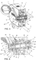
- a sensorized translational-rotary machine 40 comprises a housing 3 forming two housing openings 12 facing each other.
- the translational-rotary machine 40 further comprises a shaft 4 which forms two shaft ends 9.
- the shaft 4 is placed through the two housing openings 12.
- each opening 12 may be covered by a bellows.
- the translational-rotary machine 40 further comprises drive means 5.
- the shaft 4 is connected to the housing 3 so as to translate and/or rotate with respect to the housing 3, through the drive means 5.
- the translational-rotary machine 40 further comprises two rods 6. Each of the two rods 6 forms a gripping end 7 and a coupling end 8 opposite to the gripping end 7.
- Each of the two rods 6 is removably connected, at the coupling end 8, to a respective shaft end 9.
- the translational-rotary machine 40 further comprises wireless communication means 14 configured to communicate data and/or electric power to each other.
- the wireless communication means 14 comprise a first electronic transceiver board 10 and a second electronic transceiver board 11.
- the first electronic transceiver board 10 is placed at each shaft end 9, integral with the shaft 4.
- the second electronic transceivers 11 is placed at each coupling end 8, integral with the rod 6.
- a translational-rotary machine 40 thus configured ensures a simpler, more efficient, and more reliable communication of data and/or electric power between electronic components, i.e., the first and second electronic transceiver boards 10, 11, placed in components of the translational-rotary machine in mutual relative motion.
- wireless communication means 14 are less susceptible to damage than a sliding electrical contact system, which is instead exposed to the risk of deformations, damage, and wear.
- the wireless communication means 14 further comprise a sensor 16 placed at the gripping end 7 of each rod 6.
- the sensor 16 is configured to detect a force and/or a displacement.
- the sensor 16 is configured to detect parameters indicative of the movement of each rod 6, such as the force or torque acting on the rod 6 and the linear and/or angular displacement of the rod 6, for example.
- the information detected by the sensor 16 can be used to set, adapt, and verify the parameters of the rehabilitation therapy to which the user of the translational-rotary machine 40 is subjected.
- the sensor 16 is configured to communicate data and/or electric power with the second electronic transceiver board 11.
- such a configuration simplifies the collection and transmission, between moving parts of the translational-rotary machine 40, of data related to the exercise performed by the user using the translational-rotary machine 40.
- Such a configuration also has a smaller size and less risk of damage.
- the wireless communication means 14 further comprise an intermediary electronic transceiver board 17 placed within each rod 6, in a substantially intermediate position between the gripping end 7 and the coupling end 8.
- the intermediary electronic transceiver board 17 is configured to communicate data and/or electric power with the second electronic transceiver board 11 and with the sensor 16 of the same rod 6.
- the sensor 16 is configured to communicate data and/or electric power with the intermediary electronic transceiver board 17, and the intermediate electronic transceiver board 17 is configured to communicate such data and/or electric power with the electronic transceiver board 11.
- the intermediary electronic transceiver board 17 acts as a "mediator” ("buffer") between the sensor 16 and the second electronic transceiver board 11, thus increasing the efficiency and reliability of data and/or electric power transmission between the sensor 16 and the second electronic transceiver board 11.
- the translational-rotary machine 40 comprises two grips 15 hinged to a respective gripping end 7 of the rods 6, by means of a pin 18 which is integral with the rod 6, and one or more ball bearings 19 interposed between the pin 18 and the respective grip 15.
- the sensor 16 comprises a plurality of strain gauges adapted to detect deformations of each respective pin 18.
- the sensor 16 detects data related to the force, energy, and power used by the user to move the rods 6.
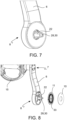
- each rod 6 comprises a coupling element 20 connected to the rod 6 at the coupling end 8.
- the coupling element 20 has a substantially truncated-pyramid shape with a polygonal base, which defines an abutting head portion 21 and a truncated-pyramid portion 22.
- the coupling element 20 further forms a through-hole 23 extending through the abutting head portion 21 and the truncated-pyramid portion 22.
- the shaft 4 forms a coupling seat 24 at each shaft end 9.
- the coupling seat 24 forms a contrast wall 25, shaped so as to accommodate the truncated-pyramid portion 22 of the coupling element 20, and a bottom wall 26.
- a threaded hole 27 is defined on the bottom wall 26.
- the translational-rotary machine 40 further comprises two knobs 28.
- Each knob 28 comprises a screwing head 29 and a threaded pin 30 connected to the screwing head 29.
- the screwing head 29 is shaped, on the one hand, so as to be adapted to abut against the abutting head portion 21 of the coupling element 20, and on the other hand, to be grippable and screwable by a user.
- the threaded pin 30 is sized to be insertable into the through-hole 23 of the coupling element 20.
- each rod 6 is connected to a respective shaft end 9
- the coupling element 20 is received in the coupling seat 24.
- knob 28 is coupled to the coupling element 20 so that the screwing head 29 abuts with the abutting head portion 21, and the threaded pin 30 is inserted through the through-hole 23 and screwed into the threaded hole 27 of the coupling seat 24.
- such a removable connection between the knob 28, the coupling seat 24 of the shaft end 9, and the coupling element 20 interposed between the knob 28 and the shaft end 9, is structurally simple and ensures a quick and firm connection.
- the truncated-pyramid portion 22 of the coupling element 20 and the contrast wall 25 of the coupling seat 24 are deformed to obtain a shape connection.
- connection between the coupling element 20 and the coupling seat 24 thus configured is advantageously less noisy and firmer.
- the truncated-pyramid portion 22 and the contrast wall 25 have a square cross-section, the truncated-pyramid portion 22 is insertable into the contrast wall 25 according to only four possible coupling timings.
- the first electronic transceiver board 10 has a discoidal shape which forms a central hole, so that, in an assembled configuration, the shaft end 9 passes through the central hole of the first electronic transceiver board 10.
- the second electronic transceiver board 11 has a discoidal shape which forms a central hole 32 delimited by a hole edge 33, so that the hole edge 33 surrounds the shaft end 9 in an assembled configuration.
- each second electronic transceiver board 11 is placed on each second electronic transceiver board 11 at the hole edge 33, at 90° from one another.
- the four magnetic detectors 31 are arranged on one side of the second electronic transceiver board 11 facing away from the housing 3 (in an assembled configuration).
- Two magnets 34 are placed on each shaft end 9, at 90° from each other, so that when the rod 6 is assembled to the shaft end 9, two of the four magnetic detectors 31 face the two magnets 34, respectively.
- such a configuration with four magnetic detectors 31 and two magnets 34 allows to determine the timing with which the rod 6 is coupled into the shaft end 9.
- the timing with which the rod 6 is coupled into the shaft end 9 can be determined according to whether or not each of the four magnetic detectors 31 detects the presence of one of the two magnets 34.
- different timing angles are determinable in the configuration where the coupling element 20 and the contrast wall 25 have prismatic shapes with a number of sides other than four, and a corresponding number of magnetic detectors 31 placed on each second electronic transceiver board 11 at the hole edge 33, and a corresponding number of magnets 34 placed on each shaft end 9.
- a rehabilitation machine 1 comprises a translational-rotary machine 40 as described above.
- the rehabilitation machine 1 comprises at least one track 2 extending along a longitudinal direction.
- the housing 3 is slidingly connected to the at least one track 2 and is configured to slide along the longitudinal direction.
- the drive means 5 are operatively connected to the shaft 4 and are configured to translate and/or rotate the shaft 4 with respect to the at least one track 2.
- a rehabilitation machine 1 thus configured has at least all of the previously highlighted advantages.
Landscapes
- Health & Medical Sciences (AREA)
- General Health & Medical Sciences (AREA)
- Physical Education & Sports Medicine (AREA)
- Pain & Pain Management (AREA)
- Vascular Medicine (AREA)
- Epidemiology (AREA)
- Cardiology (AREA)
- Rehabilitation Therapy (AREA)
- Life Sciences & Earth Sciences (AREA)
- Animal Behavior & Ethology (AREA)
- Public Health (AREA)
- Veterinary Medicine (AREA)
- Arrangements For Transmission Of Measured Signals (AREA)
Claims (11)
- Translatorische Rotationsmaschine (40), umfassend:- ein Gehäuse (3), welches zwei Gehäuseöffnungen (12) bildet, welche einander zugewandt sind;- einen Schaft (4), welcher zwei Schaftenden (9) bildet;
wobei der Schaft (4) durch die zwei Gehäuseöffnungen (12) platziert ist;- ein Antriebsmittel (5);
wobei der Schaft (4) mit dem Gehäuse (3) derart verbunden ist, dass er in Bezug auf das Gehäuse (3) durch die Antriebsmittel (5) verrückt und/oder rotiert;- zwei Stangen (6), wobei jede der zwei Stangen (6) ein Griffende (7) und ein Kupplungsende (8) bildet, welches dem Griffende (7) entgegengesetzt ist, wobei jede der zwei Stangen (6) an dem Kupplungsende (8) entfernbar mit einem entsprechenden Schaftende (9) verbunden ist;- Mittel zur drahtlosen Kommunikation (14), umfassend:- eine erste elektronische Transceiver-Platine (10), welche an jedem Schaftende (9) platziert und integral mit dem Schaft (4) ist;- eine zweite elektronische Transceiver-Platine (11), welche an jedem Kupplungsende (8) platziert und integral mit der Stange (6) ist,welche dazu eingerichtet sind, Daten und/oder elektrische Leistung zwischen den Transceiver-Platinen zu kommunizieren,wobei die Mittel zur drahtlosen Kommunikation (14) ferner einen Sensor (16) umfassen,wobei der Sensor (16) an dem Griffende (7) jeder Stange (6) platziert ist,wobei der Sensor (16) dazu eingerichtet ist, Parameter zu detektieren, welche indikativ für die Bewegung jeder Stange (6) sind, umfassend die Kraft oder das Drehmoment, welche/welches auf die Stange (6) wirkt und die lineare und/oder Winkelversetzung der Stange (6),wobei die translatorische Rotationsmaschine (40) zwei Griffe (15) umfasst, welche durch einen Stift (18), welcher integral mit der Stange (6) ist, gelenkig zu einem entsprechenden Griffende (7) der Stangen (6) sind,und wobei der Sensor (16) eine Mehrzahl von Dehnungsmessgeräten umfasst, welche dazu angepasst sind, Deformationen von jedem entsprechenden Stift (18) zu detektieren. - Translatorische Rotationsmaschine (40) nach Anspruch 1, wobei der Sensor (16) dazu eingerichtet ist, Daten und/oder elektrische Leistung mit der zweiten elektronischen Transceiver-Platine (11) zu kommunizieren.
- Translatorische Rotationsmaschine (40) nach Anspruch 1, wobei die Mittel zur drahtlosen Kommunikation (14) ferner eine intermediäre elektronische Transceiver-Platine (17) umfassen, welche innerhalb jeder Stange (6) an einer Zwischenposition zwischen dem Griffende (7) und dem Kupplungsende (8) platziert ist,
wobei die intermediäre elektronische Transceiver-Platine (17) dazu eingerichtet ist, Daten und/oder elektrische Leistung mit der zweiten elektronischen Transceiver-Platine (11) und mit dem Sensor (16) derselben Stange (6) zu kommunizieren. - Translatorische Rotationsmaschine (40) nach einem der vorhergehenden Ansprüche, wobei jede Stange (6) ein Kupplungselement (20) umfasst, welches mit der Stange (6) an dem Kupplungsende (8) verbunden ist.
- Translatorische Rotationsmaschine (40) nach Anspruch 4, wobei das Kupplungselement (20) eine Form eines Pyramidenstumpfes mit einer polygonalen Basis aufweist, welche einen anstoßenden Kopfabschnitt (21) und einen Pyramidenstumpfabschnitt (22) definiert,
wobei das Kupplungselement (20) ein Durchgangsloch (23) bildet, welches sich durch den anstoßenden Kopfabschnitt (21) und den Pyramidenstumpfabschnitt (22) erstreckt. - Translatorische Rotationsmaschine (40) nach Anspruch 5, wobei der Schaft (4) einen Kupplungssitz (24) an jedem Schaftende (9) bildet,wobei der Kupplungssitz (24) bildet:- eine Gegenwand (25), welche derart geformt ist, dass sie den Pyramidenstumpfabschnitt (22) des Kupplungselements (20) aufnimmt;- eine Bodenwand (26),und wobei ein Gewindeloch (27) an der Bodenwand (26) definiert ist.
- Translatorische Rotationsmaschine (40) nach Anspruch 6, umfassend zwei Knöpfe (28), wobei jeder Knopf (28) einen Schraubkopf (29) und einen Gewindestift (30) umfasst, welcher mit dem Schraubkopf (29) verbunden ist, wobei der Schraubkopf (29) an einer Seite derart geformt ist, dass er an den anstoßenden Kopfabschnitt (21) des Kupplungselements (20) anstößt, und an der anderen Seite durch einen Anwender greifbar und schraubbar ist,
und wobei der Gewindestift (30) derart dimensioniert ist, dass er in das Durchgangsloch (23) des Kupplungselements (20) einführbar ist. - Translatorische Rotationsmaschine (40) nach Anspruch 7, wobei in der Konfiguration, in welcher jede Stange (6) mit einem entsprechenden Schaftende (9) verbunden ist:- das Kupplungselement (20) in dem Kupplungssitz (24) aufgenommen ist;- der Knopf (28) mit dem Kupplungselement (20) derart gekoppelt ist, dass der Schraubkopf (29) an dem anstoßenden Kopfabschnitt (21) anstößt;- der Gewindestift (30) durch das Durchgangsloch (23) eingeführt und in das Gewindeloch (27) des Kupplungssitzes (24) eingeschraubt ist.
- Translatorische Rotationsmaschine (40) nach einem der Ansprüche 6 bis 8, wobei der Pyramidenstumpfabschnitt (22) des Kupplungselements (20) und die Gegenwand (25) des Kupplungssitzes (24) deformiert sind, um eine Formverbindung zu erhalten.
- Translatorische Rotationsmaschine (40) nach einem der vorhergehenden Ansprüche, wobei die zweite elektronische Transceiver-Platine (11) eine diskoidale Form aufweist, welche ein Zentralloch (32) bildet, wobei das Zentralloch (32) durch einen Lochrand (33) derart begrenzt ist, dass der Lochrand (33) das Schaftende (9) umgibt,
und optional wobei vier magnetische Detektoren (31) an jeder zweiten elektronischen Transceiver-Platine (11), an dem Lochrand (33), in 90° zueinander platziert sind, und wobei zwei Magneten (34) an jedem Schaftende (9) in 90° zueinander derart platziert sind, dass wenn die Stange (6) an dem Schaftende (9) montiert ist, zwei der vier magnetischen Detektoren (31) jeweils den zwei Magneten (34) zugewandt sind. - Rehabilitationsmaschine (1), umfassend eine translatorische Rotationsmaschine (40) nach einem der Ansprüche 1 bis 10 und wenigstens eine Spur (2), welche sich entlang einer longitudinalen Richtung erstreckt;wobei das Gehäuse (3) gleitend mit der wenigstens einen Spur (2) verbunden und dazu eingerichtet ist, entlang der longitudinalen Richtung zu gleiten;und wobei die Antriebsmittel (5) operativ mit dem Schaft (4) verbunden und dazu eingerichtet sind, den Schaft (4) in Bezug auf die wenigstens eine Spur (2) zu verrücken und/oder zu rotieren.
Priority Applications (1)
| Application Number | Priority Date | Filing Date | Title |
|---|---|---|---|
| EP21183651.5A EP4115867B1 (de) | 2021-07-05 | 2021-07-05 | Sensorgesteuerte traslo-rotationsmaschine |
Applications Claiming Priority (1)
| Application Number | Priority Date | Filing Date | Title |
|---|---|---|---|
| EP21183651.5A EP4115867B1 (de) | 2021-07-05 | 2021-07-05 | Sensorgesteuerte traslo-rotationsmaschine |
Publications (3)
| Publication Number | Publication Date |
|---|---|
| EP4115867A1 EP4115867A1 (de) | 2023-01-11 |
| EP4115867C0 EP4115867C0 (de) | 2024-10-30 |
| EP4115867B1 true EP4115867B1 (de) | 2024-10-30 |
Family
ID=77050771
Family Applications (1)
| Application Number | Title | Priority Date | Filing Date |
|---|---|---|---|
| EP21183651.5A Active EP4115867B1 (de) | 2021-07-05 | 2021-07-05 | Sensorgesteuerte traslo-rotationsmaschine |
Country Status (1)
| Country | Link |
|---|---|
| EP (1) | EP4115867B1 (de) |
Family Cites Families (3)
| Publication number | Priority date | Publication date | Assignee | Title |
|---|---|---|---|---|
| US20120330572A1 (en) * | 2009-11-28 | 2012-12-27 | David John Longman | Cyclic Cranked System Method and Related Devices |
| WO2013096583A1 (en) * | 2011-12-20 | 2013-06-27 | Frier Ethan Perry | Communicating information regarding status of vehicle operation |
| EP2865363B1 (de) * | 2013-10-25 | 2016-05-25 | Polibrixia S.r.l. | Körperübungsmaschine |
-
2021
- 2021-07-05 EP EP21183651.5A patent/EP4115867B1/de active Active
Also Published As
| Publication number | Publication date |
|---|---|
| EP4115867A1 (de) | 2023-01-11 |
| EP4115867C0 (de) | 2024-10-30 |
Similar Documents
| Publication | Publication Date | Title |
|---|---|---|
| KR101819146B1 (ko) | 보조힘 판단이 가능한 운동보조장치 및 운동보조장치를 구비한 피지컬 피트니스 장비 | |
| EP3406083B1 (de) | Bestimmung des gewichts und der wiederholungen bei einem fitnessgerät ohne mechanische stosseinwirkung | |
| US10994408B2 (en) | Device capable of simulating limb of humanoid robot | |
| US20050004483A1 (en) | Bi-point detection type heart-rate monitor and its heart-rate monitoring method | |
| EP4316408A1 (de) | Eingabevorrichtung und chirurgischer roboter | |
| US11117018B2 (en) | System for measuring, monitoring and displaying physical parameters of exercises on selectorized fitness machines | |
| CN113910279A (zh) | 一种感知驱动一体化刚柔耦合手指及柔顺型机器人灵巧手 | |
| CA2836327A1 (en) | Device for measuring spinal mobility | |
| Zhang et al. | Design of a novel elastic torque sensor for hand injuries rehabilitation based on bowden cable | |
| CN108837422A (zh) | 一种新型手腕康复机器人 | |
| US12161909B2 (en) | Exercising apparatus with a limb support, and method for determining the force acting on a limb support of an exercising apparatus | |
| EP4115867A1 (de) | Sensorgesteuerte traslo-rotationsmaschine | |
| CN110893273A (zh) | 等速肌力训练设备 | |
| CN106236515A (zh) | 一种手臂自主训练装置 | |
| JPS5828492A (ja) | リモート・センタ・コンプライアンス装置用力検出装置 | |
| CN105476818A (zh) | 康复训练装置 | |
| CN109682280A (zh) | 一种抽油机箱体内腔尺寸检测装置及检测方法 | |
| US20220091629A1 (en) | Inductive joystick | |
| CN220751364U (zh) | 一种发动机振动幅度测试台 | |
| CN113485521B (zh) | 一种可实现六维力和运动状态测量的操控手柄 | |
| CN103657038B (zh) | 一种铅球核心力量训练及信息反馈监控装置 | |
| KR20180028047A (ko) | 보조힘 판단이 가능한 운동보조장치 및 운동보조장치를 구비한 피지컬 피트니스 장비 | |
| CN224263597U (zh) | 一种数据手套 | |
| CN118902463B (zh) | 一种用于肌张力评估的力反馈装置及方法 | |
| CN223815067U (zh) | 散热器壳体的平整度检测装置 |
Legal Events
| Date | Code | Title | Description |
|---|---|---|---|
| PUAI | Public reference made under article 153(3) epc to a published international application that has entered the european phase |
Free format text: ORIGINAL CODE: 0009012 |
|
| STAA | Information on the status of an ep patent application or granted ep patent |
Free format text: STATUS: THE APPLICATION HAS BEEN PUBLISHED |
|
| AK | Designated contracting states |
Kind code of ref document: A1 Designated state(s): AL AT BE BG CH CY CZ DE DK EE ES FI FR GB GR HR HU IE IS IT LI LT LU LV MC MK MT NL NO PL PT RO RS SE SI SK SM TR |
|
| STAA | Information on the status of an ep patent application or granted ep patent |
Free format text: STATUS: REQUEST FOR EXAMINATION WAS MADE |
|
| 17P | Request for examination filed |
Effective date: 20230620 |
|
| RBV | Designated contracting states (corrected) |
Designated state(s): AL AT BE BG CH CY CZ DE DK EE ES FI FR GB GR HR HU IE IS IT LI LT LU LV MC MK MT NL NO PL PT RO RS SE SI SK SM TR |
|
| GRAP | Despatch of communication of intention to grant a patent |
Free format text: ORIGINAL CODE: EPIDOSNIGR1 |
|
| STAA | Information on the status of an ep patent application or granted ep patent |
Free format text: STATUS: GRANT OF PATENT IS INTENDED |
|
| INTG | Intention to grant announced |
Effective date: 20240527 |
|
| GRAS | Grant fee paid |
Free format text: ORIGINAL CODE: EPIDOSNIGR3 |
|
| GRAA | (expected) grant |
Free format text: ORIGINAL CODE: 0009210 |
|
| STAA | Information on the status of an ep patent application or granted ep patent |
Free format text: STATUS: THE PATENT HAS BEEN GRANTED |
|
| AK | Designated contracting states |
Kind code of ref document: B1 Designated state(s): AL AT BE BG CH CY CZ DE DK EE ES FI FR GB GR HR HU IE IS IT LI LT LU LV MC MK MT NL NO PL PT RO RS SE SI SK SM TR |
|
| REG | Reference to a national code |
Ref country code: GB Ref legal event code: FG4D |
|
| REG | Reference to a national code |
Ref country code: CH Ref legal event code: EP |
|
| REG | Reference to a national code |
Ref country code: IE Ref legal event code: FG4D |
|
| REG | Reference to a national code |
Ref country code: DE Ref legal event code: R096 Ref document number: 602021020892 Country of ref document: DE |
|
| U01 | Request for unitary effect filed |
Effective date: 20241122 |
|
| U07 | Unitary effect registered |
Designated state(s): AT BE BG DE DK EE FI FR IT LT LU LV MT NL PT RO SE SI Effective date: 20241202 |
|
| PG25 | Lapsed in a contracting state [announced via postgrant information from national office to epo] |
Ref country code: IS Free format text: LAPSE BECAUSE OF FAILURE TO SUBMIT A TRANSLATION OF THE DESCRIPTION OR TO PAY THE FEE WITHIN THE PRESCRIBED TIME-LIMIT Effective date: 20250228 Ref country code: HR Free format text: LAPSE BECAUSE OF FAILURE TO SUBMIT A TRANSLATION OF THE DESCRIPTION OR TO PAY THE FEE WITHIN THE PRESCRIBED TIME-LIMIT Effective date: 20241030 |
|
| PG25 | Lapsed in a contracting state [announced via postgrant information from national office to epo] |
Ref country code: ES Free format text: LAPSE BECAUSE OF FAILURE TO SUBMIT A TRANSLATION OF THE DESCRIPTION OR TO PAY THE FEE WITHIN THE PRESCRIBED TIME-LIMIT Effective date: 20241030 |
|
| PG25 | Lapsed in a contracting state [announced via postgrant information from national office to epo] |
Ref country code: NO Free format text: LAPSE BECAUSE OF FAILURE TO SUBMIT A TRANSLATION OF THE DESCRIPTION OR TO PAY THE FEE WITHIN THE PRESCRIBED TIME-LIMIT Effective date: 20250130 |
|
| PG25 | Lapsed in a contracting state [announced via postgrant information from national office to epo] |
Ref country code: GR Free format text: LAPSE BECAUSE OF FAILURE TO SUBMIT A TRANSLATION OF THE DESCRIPTION OR TO PAY THE FEE WITHIN THE PRESCRIBED TIME-LIMIT Effective date: 20250131 |
|
| PG25 | Lapsed in a contracting state [announced via postgrant information from national office to epo] |
Ref country code: PL Free format text: LAPSE BECAUSE OF FAILURE TO SUBMIT A TRANSLATION OF THE DESCRIPTION OR TO PAY THE FEE WITHIN THE PRESCRIBED TIME-LIMIT Effective date: 20241030 |
|
| PG25 | Lapsed in a contracting state [announced via postgrant information from national office to epo] |
Ref country code: RS Free format text: LAPSE BECAUSE OF FAILURE TO SUBMIT A TRANSLATION OF THE DESCRIPTION OR TO PAY THE FEE WITHIN THE PRESCRIBED TIME-LIMIT Effective date: 20250130 |
|
| U20 | Renewal fee for the european patent with unitary effect paid |
Year of fee payment: 5 Effective date: 20250523 |
|
| PG25 | Lapsed in a contracting state [announced via postgrant information from national office to epo] |
Ref country code: SM Free format text: LAPSE BECAUSE OF FAILURE TO SUBMIT A TRANSLATION OF THE DESCRIPTION OR TO PAY THE FEE WITHIN THE PRESCRIBED TIME-LIMIT Effective date: 20241030 |
|
| PG25 | Lapsed in a contracting state [announced via postgrant information from national office to epo] |
Ref country code: SK Free format text: LAPSE BECAUSE OF FAILURE TO SUBMIT A TRANSLATION OF THE DESCRIPTION OR TO PAY THE FEE WITHIN THE PRESCRIBED TIME-LIMIT Effective date: 20241030 |
|
| PG25 | Lapsed in a contracting state [announced via postgrant information from national office to epo] |
Ref country code: CZ Free format text: LAPSE BECAUSE OF FAILURE TO SUBMIT A TRANSLATION OF THE DESCRIPTION OR TO PAY THE FEE WITHIN THE PRESCRIBED TIME-LIMIT Effective date: 20241030 |
|
| PLBE | No opposition filed within time limit |
Free format text: ORIGINAL CODE: 0009261 |
|
| STAA | Information on the status of an ep patent application or granted ep patent |
Free format text: STATUS: NO OPPOSITION FILED WITHIN TIME LIMIT |
|
| 26N | No opposition filed |
Effective date: 20250731 |
|
| REG | Reference to a national code |
Ref country code: CH Ref legal event code: H13 Free format text: ST27 STATUS EVENT CODE: U-0-0-H10-H13 (AS PROVIDED BY THE NATIONAL OFFICE) Effective date: 20260224 |
|
| GBPC | Gb: european patent ceased through non-payment of renewal fee |
Effective date: 20250705 |
|
| PG25 | Lapsed in a contracting state [announced via postgrant information from national office to epo] |
Ref country code: GB Free format text: LAPSE BECAUSE OF NON-PAYMENT OF DUE FEES Effective date: 20250705 |
|
| PG25 | Lapsed in a contracting state [announced via postgrant information from national office to epo] |
Ref country code: CH Free format text: LAPSE BECAUSE OF NON-PAYMENT OF DUE FEES Effective date: 20250731 |