EP4115867B1 - Sensorized traslo-rotary machine - Google Patents
Sensorized traslo-rotary machine Download PDFInfo
- Publication number
- EP4115867B1 EP4115867B1 EP21183651.5A EP21183651A EP4115867B1 EP 4115867 B1 EP4115867 B1 EP 4115867B1 EP 21183651 A EP21183651 A EP 21183651A EP 4115867 B1 EP4115867 B1 EP 4115867B1
- Authority
- EP
- European Patent Office
- Prior art keywords
- translational
- rotary machine
- rod
- shaft
- coupling
- Prior art date
- Legal status (The legal status is an assumption and is not a legal conclusion. Google has not performed a legal analysis and makes no representation as to the accuracy of the status listed.)
- Active
Links
Images




Classifications
-
- A—HUMAN NECESSITIES
- A61—MEDICAL OR VETERINARY SCIENCE; HYGIENE
- A61H—PHYSICAL THERAPY APPARATUS, e.g. DEVICES FOR LOCATING OR STIMULATING REFLEX POINTS IN THE BODY; ARTIFICIAL RESPIRATION; MASSAGE; BATHING DEVICES FOR SPECIAL THERAPEUTIC OR HYGIENIC PURPOSES OR SPECIFIC PARTS OF THE BODY
- A61H1/00—Apparatus for passive exercising; Vibrating apparatus; Chiropractic devices, e.g. body impacting devices, external devices for briefly extending or aligning unbroken bones
- A61H1/02—Stretching or bending or torsioning apparatus for exercising
- A61H1/0274—Stretching or bending or torsioning apparatus for exercising for the upper limbs
-
- A—HUMAN NECESSITIES
- A61—MEDICAL OR VETERINARY SCIENCE; HYGIENE
- A61H—PHYSICAL THERAPY APPARATUS, e.g. DEVICES FOR LOCATING OR STIMULATING REFLEX POINTS IN THE BODY; ARTIFICIAL RESPIRATION; MASSAGE; BATHING DEVICES FOR SPECIAL THERAPEUTIC OR HYGIENIC PURPOSES OR SPECIFIC PARTS OF THE BODY
- A61H1/00—Apparatus for passive exercising; Vibrating apparatus; Chiropractic devices, e.g. body impacting devices, external devices for briefly extending or aligning unbroken bones
- A61H1/02—Stretching or bending or torsioning apparatus for exercising
- A61H1/0237—Stretching or bending or torsioning apparatus for exercising for the lower limbs
- A61H1/0266—Foot
-
- A—HUMAN NECESSITIES
- A63—SPORTS; GAMES; AMUSEMENTS
- A63B—APPARATUS FOR PHYSICAL TRAINING, GYMNASTICS, SWIMMING, CLIMBING, OR FENCING; BALL GAMES; TRAINING EQUIPMENT
- A63B22/00—Exercising apparatus specially adapted for conditioning the cardio-vascular system, for training agility or co-ordination of movements
- A63B22/0002—Exercising apparatus specially adapted for conditioning the cardio-vascular system, for training agility or co-ordination of movements involving an exercising of arms
-
- A—HUMAN NECESSITIES
- A63—SPORTS; GAMES; AMUSEMENTS
- A63B—APPARATUS FOR PHYSICAL TRAINING, GYMNASTICS, SWIMMING, CLIMBING, OR FENCING; BALL GAMES; TRAINING EQUIPMENT
- A63B22/00—Exercising apparatus specially adapted for conditioning the cardio-vascular system, for training agility or co-ordination of movements
- A63B22/06—Exercising apparatus specially adapted for conditioning the cardio-vascular system, for training agility or co-ordination of movements with support elements performing a rotating cycling movement, i.e. a closed path movement
- A63B22/0605—Exercising apparatus specially adapted for conditioning the cardio-vascular system, for training agility or co-ordination of movements with support elements performing a rotating cycling movement, i.e. a closed path movement performing a circular movement, e.g. ergometers
-
- A—HUMAN NECESSITIES
- A61—MEDICAL OR VETERINARY SCIENCE; HYGIENE
- A61H—PHYSICAL THERAPY APPARATUS, e.g. DEVICES FOR LOCATING OR STIMULATING REFLEX POINTS IN THE BODY; ARTIFICIAL RESPIRATION; MASSAGE; BATHING DEVICES FOR SPECIAL THERAPEUTIC OR HYGIENIC PURPOSES OR SPECIFIC PARTS OF THE BODY
- A61H2201/00—Characteristics of apparatus not provided for in the preceding codes
- A61H2201/12—Driving means
- A61H2201/1253—Driving means driven by a human being, e.g. hand driven
- A61H2201/1261—Driving means driven by a human being, e.g. hand driven combined with active exercising of the patient
-
- A—HUMAN NECESSITIES
- A61—MEDICAL OR VETERINARY SCIENCE; HYGIENE
- A61H—PHYSICAL THERAPY APPARATUS, e.g. DEVICES FOR LOCATING OR STIMULATING REFLEX POINTS IN THE BODY; ARTIFICIAL RESPIRATION; MASSAGE; BATHING DEVICES FOR SPECIAL THERAPEUTIC OR HYGIENIC PURPOSES OR SPECIFIC PARTS OF THE BODY
- A61H2201/00—Characteristics of apparatus not provided for in the preceding codes
- A61H2201/16—Physical interface with patient
- A61H2201/1602—Physical interface with patient kind of interface, e.g. head rest, knee support or lumbar support
- A61H2201/1635—Hand or arm, e.g. handle
-
- A—HUMAN NECESSITIES
- A61—MEDICAL OR VETERINARY SCIENCE; HYGIENE
- A61H—PHYSICAL THERAPY APPARATUS, e.g. DEVICES FOR LOCATING OR STIMULATING REFLEX POINTS IN THE BODY; ARTIFICIAL RESPIRATION; MASSAGE; BATHING DEVICES FOR SPECIAL THERAPEUTIC OR HYGIENIC PURPOSES OR SPECIFIC PARTS OF THE BODY
- A61H2201/00—Characteristics of apparatus not provided for in the preceding codes
- A61H2201/16—Physical interface with patient
- A61H2201/1657—Movement of interface, i.e. force application means
- A61H2201/1664—Movement of interface, i.e. force application means linear
-
- A—HUMAN NECESSITIES
- A61—MEDICAL OR VETERINARY SCIENCE; HYGIENE
- A61H—PHYSICAL THERAPY APPARATUS, e.g. DEVICES FOR LOCATING OR STIMULATING REFLEX POINTS IN THE BODY; ARTIFICIAL RESPIRATION; MASSAGE; BATHING DEVICES FOR SPECIAL THERAPEUTIC OR HYGIENIC PURPOSES OR SPECIFIC PARTS OF THE BODY
- A61H2201/00—Characteristics of apparatus not provided for in the preceding codes
- A61H2201/16—Physical interface with patient
- A61H2201/1657—Movement of interface, i.e. force application means
- A61H2201/1671—Movement of interface, i.e. force application means rotational
-
- A—HUMAN NECESSITIES
- A61—MEDICAL OR VETERINARY SCIENCE; HYGIENE
- A61H—PHYSICAL THERAPY APPARATUS, e.g. DEVICES FOR LOCATING OR STIMULATING REFLEX POINTS IN THE BODY; ARTIFICIAL RESPIRATION; MASSAGE; BATHING DEVICES FOR SPECIAL THERAPEUTIC OR HYGIENIC PURPOSES OR SPECIFIC PARTS OF THE BODY
- A61H2201/00—Characteristics of apparatus not provided for in the preceding codes
- A61H2201/50—Control means thereof
- A61H2201/5058—Sensors or detectors
- A61H2201/5061—Force sensors
-
- A—HUMAN NECESSITIES
- A61—MEDICAL OR VETERINARY SCIENCE; HYGIENE
- A61H—PHYSICAL THERAPY APPARATUS, e.g. DEVICES FOR LOCATING OR STIMULATING REFLEX POINTS IN THE BODY; ARTIFICIAL RESPIRATION; MASSAGE; BATHING DEVICES FOR SPECIAL THERAPEUTIC OR HYGIENIC PURPOSES OR SPECIFIC PARTS OF THE BODY
- A61H2201/00—Characteristics of apparatus not provided for in the preceding codes
- A61H2201/50—Control means thereof
- A61H2201/5058—Sensors or detectors
- A61H2201/5069—Angle sensors
-
- A—HUMAN NECESSITIES
- A61—MEDICAL OR VETERINARY SCIENCE; HYGIENE
- A61H—PHYSICAL THERAPY APPARATUS, e.g. DEVICES FOR LOCATING OR STIMULATING REFLEX POINTS IN THE BODY; ARTIFICIAL RESPIRATION; MASSAGE; BATHING DEVICES FOR SPECIAL THERAPEUTIC OR HYGIENIC PURPOSES OR SPECIFIC PARTS OF THE BODY
- A61H2201/00—Characteristics of apparatus not provided for in the preceding codes
- A61H2201/50—Control means thereof
- A61H2201/5097—Control means thereof wireless
-
- A—HUMAN NECESSITIES
- A63—SPORTS; GAMES; AMUSEMENTS
- A63B—APPARATUS FOR PHYSICAL TRAINING, GYMNASTICS, SWIMMING, CLIMBING, OR FENCING; BALL GAMES; TRAINING EQUIPMENT
- A63B22/00—Exercising apparatus specially adapted for conditioning the cardio-vascular system, for training agility or co-ordination of movements
- A63B22/06—Exercising apparatus specially adapted for conditioning the cardio-vascular system, for training agility or co-ordination of movements with support elements performing a rotating cycling movement, i.e. a closed path movement
- A63B22/0605—Exercising apparatus specially adapted for conditioning the cardio-vascular system, for training agility or co-ordination of movements with support elements performing a rotating cycling movement, i.e. a closed path movement performing a circular movement, e.g. ergometers
- A63B2022/0611—Particular details or arrangement of cranks
-
- A—HUMAN NECESSITIES
- A63—SPORTS; GAMES; AMUSEMENTS
- A63B—APPARATUS FOR PHYSICAL TRAINING, GYMNASTICS, SWIMMING, CLIMBING, OR FENCING; BALL GAMES; TRAINING EQUIPMENT
- A63B22/00—Exercising apparatus specially adapted for conditioning the cardio-vascular system, for training agility or co-ordination of movements
- A63B22/20—Exercising apparatus specially adapted for conditioning the cardio-vascular system, for training agility or co-ordination of movements using rollers, wheels, castors or the like, e.g. gliding means, to be moved over the floor or other surface, e.g. guide tracks, during exercising
- A63B22/201—Exercising apparatus specially adapted for conditioning the cardio-vascular system, for training agility or co-ordination of movements using rollers, wheels, castors or the like, e.g. gliding means, to be moved over the floor or other surface, e.g. guide tracks, during exercising for moving a support element in reciprocating translation, i.e. for sliding back and forth on a guide track
- A63B22/203—Exercising apparatus specially adapted for conditioning the cardio-vascular system, for training agility or co-ordination of movements using rollers, wheels, castors or the like, e.g. gliding means, to be moved over the floor or other surface, e.g. guide tracks, during exercising for moving a support element in reciprocating translation, i.e. for sliding back and forth on a guide track in a horizontal plane
-
- A—HUMAN NECESSITIES
- A63—SPORTS; GAMES; AMUSEMENTS
- A63B—APPARATUS FOR PHYSICAL TRAINING, GYMNASTICS, SWIMMING, CLIMBING, OR FENCING; BALL GAMES; TRAINING EQUIPMENT
- A63B2220/00—Measuring of physical parameters relating to sporting activity
- A63B2220/20—Distances or displacements
-
- A—HUMAN NECESSITIES
- A63—SPORTS; GAMES; AMUSEMENTS
- A63B—APPARATUS FOR PHYSICAL TRAINING, GYMNASTICS, SWIMMING, CLIMBING, OR FENCING; BALL GAMES; TRAINING EQUIPMENT
- A63B2220/00—Measuring of physical parameters relating to sporting activity
- A63B2220/30—Speed
- A63B2220/36—Speed measurement by electric or magnetic parameters
-
- A—HUMAN NECESSITIES
- A63—SPORTS; GAMES; AMUSEMENTS
- A63B—APPARATUS FOR PHYSICAL TRAINING, GYMNASTICS, SWIMMING, CLIMBING, OR FENCING; BALL GAMES; TRAINING EQUIPMENT
- A63B2220/00—Measuring of physical parameters relating to sporting activity
- A63B2220/50—Force related parameters
- A63B2220/51—Force
-
- A—HUMAN NECESSITIES
- A63—SPORTS; GAMES; AMUSEMENTS
- A63B—APPARATUS FOR PHYSICAL TRAINING, GYMNASTICS, SWIMMING, CLIMBING, OR FENCING; BALL GAMES; TRAINING EQUIPMENT
- A63B2220/00—Measuring of physical parameters relating to sporting activity
- A63B2220/50—Force related parameters
- A63B2220/54—Torque
-
- A—HUMAN NECESSITIES
- A63—SPORTS; GAMES; AMUSEMENTS
- A63B—APPARATUS FOR PHYSICAL TRAINING, GYMNASTICS, SWIMMING, CLIMBING, OR FENCING; BALL GAMES; TRAINING EQUIPMENT
- A63B2225/00—Miscellaneous features of sport apparatus, devices or equipment
- A63B2225/50—Wireless data transmission, e.g. by radio transmitters or telemetry
Definitions
- the present invention relates to a sensorized translational-rotary machine, and in particular to a rehabilitation machine for the exercise and rehabilitation of the upper limbs comprising such a translational-rotary machine, for both passive and active techniques.
- the rehabilitation therapy of the upper limbs is a highly important clinical practice aimed at restoring the motor skills of a patient affected by paresis or hemiparesis of various etiology.
- Rehabilitation can be either passive or active.
- Active rehabilitation instead requires the direct effort of the patient's limb, while the mechanical aid follows the movements thereof opposing a resistance.
- Rehabilitation devices are known, which are provided with electronic components, such as sensors, adapted to detect parameters indicative of the performance of the patient undergoing rehabilitation therapy, and to transmit the detected data to further electronic components, such as receivers or a central computer, inside the device.
- electronic components such as sensors, adapted to detect parameters indicative of the performance of the patient undergoing rehabilitation therapy, and to transmit the detected data to further electronic components, such as receivers or a central computer, inside the device.
- Such mutually communicating electronic components are generally arranged in parts of the device which are in relative motion with each other during normal use of the device.
- the sensors are often arranged at the moving parts of the device in direct contact with the user, such as rods or pedals, for example, while the receivers are arranged in the housing of the rehabilitation device.
- connection between sensors and receivers which allows to power the sensors and transmit data between the sensors and the receivers, is generally obtained by electrical wiring.
- US2012330572A1 discloses a cyclic cranked system data gathering system has at least one crank arm operable by a limb of a user, at least one data gathering device each mounted to a respective crank arm and having at least one respective sensor measuring the deformation of the crank.
- WO2013096583A1 discloses a lighting system that uses a wide range of sensors, automated functionality, and communication modules for providing visual indications to others regarding the state of a bicycle and/or its operator.
- EP2865363A1 discloses a physical exercise machine for the rehabilitation or training of limbs for both passive and active therapies.
- a sensorized translational-rotary machine 40 comprises a housing 3 forming two housing openings 12 facing each other.
- the translational-rotary machine 40 further comprises a shaft 4 which forms two shaft ends 9.
- the shaft 4 is placed through the two housing openings 12.
- each opening 12 may be covered by a bellows.
- the translational-rotary machine 40 further comprises drive means 5.
- the shaft 4 is connected to the housing 3 so as to translate and/or rotate with respect to the housing 3, through the drive means 5.
- the translational-rotary machine 40 further comprises two rods 6. Each of the two rods 6 forms a gripping end 7 and a coupling end 8 opposite to the gripping end 7.
- Each of the two rods 6 is removably connected, at the coupling end 8, to a respective shaft end 9.
- the translational-rotary machine 40 further comprises wireless communication means 14 configured to communicate data and/or electric power to each other.
- the wireless communication means 14 comprise a first electronic transceiver board 10 and a second electronic transceiver board 11.
- the first electronic transceiver board 10 is placed at each shaft end 9, integral with the shaft 4.
- the second electronic transceivers 11 is placed at each coupling end 8, integral with the rod 6.
- a translational-rotary machine 40 thus configured ensures a simpler, more efficient, and more reliable communication of data and/or electric power between electronic components, i.e., the first and second electronic transceiver boards 10, 11, placed in components of the translational-rotary machine in mutual relative motion.
- wireless communication means 14 are less susceptible to damage than a sliding electrical contact system, which is instead exposed to the risk of deformations, damage, and wear.
- the wireless communication means 14 further comprise a sensor 16 placed at the gripping end 7 of each rod 6.
- the sensor 16 is configured to detect a force and/or a displacement.
- the sensor 16 is configured to detect parameters indicative of the movement of each rod 6, such as the force or torque acting on the rod 6 and the linear and/or angular displacement of the rod 6, for example.
- the information detected by the sensor 16 can be used to set, adapt, and verify the parameters of the rehabilitation therapy to which the user of the translational-rotary machine 40 is subjected.
- the sensor 16 is configured to communicate data and/or electric power with the second electronic transceiver board 11.
- such a configuration simplifies the collection and transmission, between moving parts of the translational-rotary machine 40, of data related to the exercise performed by the user using the translational-rotary machine 40.
- Such a configuration also has a smaller size and less risk of damage.
- the wireless communication means 14 further comprise an intermediary electronic transceiver board 17 placed within each rod 6, in a substantially intermediate position between the gripping end 7 and the coupling end 8.
- the intermediary electronic transceiver board 17 is configured to communicate data and/or electric power with the second electronic transceiver board 11 and with the sensor 16 of the same rod 6.
- the sensor 16 is configured to communicate data and/or electric power with the intermediary electronic transceiver board 17, and the intermediate electronic transceiver board 17 is configured to communicate such data and/or electric power with the electronic transceiver board 11.
- the intermediary electronic transceiver board 17 acts as a "mediator” ("buffer") between the sensor 16 and the second electronic transceiver board 11, thus increasing the efficiency and reliability of data and/or electric power transmission between the sensor 16 and the second electronic transceiver board 11.
- the translational-rotary machine 40 comprises two grips 15 hinged to a respective gripping end 7 of the rods 6, by means of a pin 18 which is integral with the rod 6, and one or more ball bearings 19 interposed between the pin 18 and the respective grip 15.
- the sensor 16 comprises a plurality of strain gauges adapted to detect deformations of each respective pin 18.
- the sensor 16 detects data related to the force, energy, and power used by the user to move the rods 6.
- each rod 6 comprises a coupling element 20 connected to the rod 6 at the coupling end 8.
- the coupling element 20 has a substantially truncated-pyramid shape with a polygonal base, which defines an abutting head portion 21 and a truncated-pyramid portion 22.
- the coupling element 20 further forms a through-hole 23 extending through the abutting head portion 21 and the truncated-pyramid portion 22.
- the shaft 4 forms a coupling seat 24 at each shaft end 9.
- the coupling seat 24 forms a contrast wall 25, shaped so as to accommodate the truncated-pyramid portion 22 of the coupling element 20, and a bottom wall 26.
- a threaded hole 27 is defined on the bottom wall 26.
- the translational-rotary machine 40 further comprises two knobs 28.
- Each knob 28 comprises a screwing head 29 and a threaded pin 30 connected to the screwing head 29.
- the screwing head 29 is shaped, on the one hand, so as to be adapted to abut against the abutting head portion 21 of the coupling element 20, and on the other hand, to be grippable and screwable by a user.
- the threaded pin 30 is sized to be insertable into the through-hole 23 of the coupling element 20.
- each rod 6 is connected to a respective shaft end 9
- the coupling element 20 is received in the coupling seat 24.
- knob 28 is coupled to the coupling element 20 so that the screwing head 29 abuts with the abutting head portion 21, and the threaded pin 30 is inserted through the through-hole 23 and screwed into the threaded hole 27 of the coupling seat 24.
- such a removable connection between the knob 28, the coupling seat 24 of the shaft end 9, and the coupling element 20 interposed between the knob 28 and the shaft end 9, is structurally simple and ensures a quick and firm connection.
- the truncated-pyramid portion 22 of the coupling element 20 and the contrast wall 25 of the coupling seat 24 are deformed to obtain a shape connection.
- connection between the coupling element 20 and the coupling seat 24 thus configured is advantageously less noisy and firmer.
- the truncated-pyramid portion 22 and the contrast wall 25 have a square cross-section, the truncated-pyramid portion 22 is insertable into the contrast wall 25 according to only four possible coupling timings.
- the first electronic transceiver board 10 has a discoidal shape which forms a central hole, so that, in an assembled configuration, the shaft end 9 passes through the central hole of the first electronic transceiver board 10.
- the second electronic transceiver board 11 has a discoidal shape which forms a central hole 32 delimited by a hole edge 33, so that the hole edge 33 surrounds the shaft end 9 in an assembled configuration.
- each second electronic transceiver board 11 is placed on each second electronic transceiver board 11 at the hole edge 33, at 90° from one another.
- the four magnetic detectors 31 are arranged on one side of the second electronic transceiver board 11 facing away from the housing 3 (in an assembled configuration).
- Two magnets 34 are placed on each shaft end 9, at 90° from each other, so that when the rod 6 is assembled to the shaft end 9, two of the four magnetic detectors 31 face the two magnets 34, respectively.
- such a configuration with four magnetic detectors 31 and two magnets 34 allows to determine the timing with which the rod 6 is coupled into the shaft end 9.
- the timing with which the rod 6 is coupled into the shaft end 9 can be determined according to whether or not each of the four magnetic detectors 31 detects the presence of one of the two magnets 34.
- different timing angles are determinable in the configuration where the coupling element 20 and the contrast wall 25 have prismatic shapes with a number of sides other than four, and a corresponding number of magnetic detectors 31 placed on each second electronic transceiver board 11 at the hole edge 33, and a corresponding number of magnets 34 placed on each shaft end 9.
- a rehabilitation machine 1 comprises a translational-rotary machine 40 as described above.
- the rehabilitation machine 1 comprises at least one track 2 extending along a longitudinal direction.
- the housing 3 is slidingly connected to the at least one track 2 and is configured to slide along the longitudinal direction.
- the drive means 5 are operatively connected to the shaft 4 and are configured to translate and/or rotate the shaft 4 with respect to the at least one track 2.
- a rehabilitation machine 1 thus configured has at least all of the previously highlighted advantages.
Landscapes
- Health & Medical Sciences (AREA)
- General Health & Medical Sciences (AREA)
- Physical Education & Sports Medicine (AREA)
- Pain & Pain Management (AREA)
- Vascular Medicine (AREA)
- Epidemiology (AREA)
- Cardiology (AREA)
- Rehabilitation Therapy (AREA)
- Life Sciences & Earth Sciences (AREA)
- Animal Behavior & Ethology (AREA)
- Public Health (AREA)
- Veterinary Medicine (AREA)
- Arrangements For Transmission Of Measured Signals (AREA)
Description
- The present invention relates to a sensorized translational-rotary machine, and in particular to a rehabilitation machine for the exercise and rehabilitation of the upper limbs comprising such a translational-rotary machine, for both passive and active techniques.
- The rehabilitation therapy of the upper limbs is a highly important clinical practice aimed at restoring the motor skills of a patient affected by paresis or hemiparesis of various etiology.
- There are various techniques which can be used for motor rehabilitation; one of the most effective is certainly that including the use of appropriate rehabilitation devices.
- Rehabilitation can be either passive or active.
- In passive rehabilitation, the machine works on the limb, which is thus induced to perform special movements or functions the purpose of which is to restore the heavily compromised motility.
- Active rehabilitation instead requires the direct effort of the patient's limb, while the mechanical aid follows the movements thereof opposing a resistance.
- Rehabilitation devices are known, which are provided with electronic components, such as sensors, adapted to detect parameters indicative of the performance of the patient undergoing rehabilitation therapy, and to transmit the detected data to further electronic components, such as receivers or a central computer, inside the device.
- Such mutually communicating electronic components are generally arranged in parts of the device which are in relative motion with each other during normal use of the device.
- For example, the sensors are often arranged at the moving parts of the device in direct contact with the user, such as rods or pedals, for example, while the receivers are arranged in the housing of the rehabilitation device.
- The connection between sensors and receivers, which allows to power the sensors and transmit data between the sensors and the receivers, is generally obtained by electrical wiring.
- However, such wirings extending through components in mutual relative motion are structurally complex and subject to undesirable stresses.
- Furthermore, these wirings require collapsible and cumbersome configurations to accommodate for the relative movement and provide the necessary protection.
- These solutions are expensive, unreliable in the long run, and require frequent maintenance.
US2012330572A1 discloses a cyclic cranked system data gathering system has at least one crank arm operable by a limb of a user, at least one data gathering device each mounted to a respective crank arm and having at least one respective sensor measuring the deformation of the crank.WO2013096583A1 discloses a lighting system that uses a wide range of sensors, automated functionality, and communication modules for providing visual indications to others regarding the state of a bicycle and/or its operator.EP2865363A1 discloses a physical exercise machine for the rehabilitation or training of limbs for both passive and active therapies. - Therefore, it is the object of the present invention to provide a translational-rotary machine having features such as to obviate at least some of the drawbacks of the prior art.
- It is a particular object of the present invention to provide a translational-rotary machine having electronic components placed in machine components in mutual relative motion, which communicate data and/or electric power through a structural configuration which is simpler, more efficient, more reliable, less cumbersome, and less susceptible to possible damage.
- These and other objects are achieved by a translational-rotary machine according to
claim 1. The dependent claims relate to advantageous and preferred embodiments of the invention. - Further advantageous aspects of the invention will become apparent from the following description of some embodiments thereof given by way of non-limiting example, with reference to the accompanying drawings, in which:
-
figure 1 is a perspective view of a cross-section of a partially disassembled component of a translational-rotary machine according to an embodiment of the invention; -
figure 2 is a detail view of the partially disassembled component infigure 1 ; -
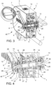
figure 3 is a perspective view of a cross-section of the component infigure 1 in an assembled configuration; -
figure 4 is a detail view of the assembled component infigure 3 ; -
figure 5 is a further detail view of the assembled component infigure 3 ; -
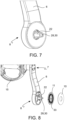
figure 6 is a detail view of a further component, in the disassembled configuration, of the translational-rotary machine infigure 1 ; -
figure 7 is a view of the component infigure 6 in an assembled configuration; -
figure 8 is a perspective view of a further component, in a partially disassembled configuration, of the translational-rotary machine infigure 1 ; -
figure 9 is a detail view of the component infigure 8 ; -
figure 10 is a front longitudinal section view of a further component of the translational-rotary machine infigure 1 ; -
figure 11 is a side view of a component of the translational-rotary machine infigure 1 ; -
figure 12 is a perspective view of the component infigure 11 ; -
figure 13 is a front longitudinal section view of a further component of the translational-rotary machine infigure 1 ; -
figure 14 is a longitudinal section perspective view of the component infigure 13 . - With reference to the figures, a sensorized translational-
rotary machine 40 comprises ahousing 3 forming twohousing openings 12 facing each other. - The translational-
rotary machine 40 further comprises ashaft 4 which forms twoshaft ends 9. - The
shaft 4 is placed through the twohousing openings 12. - Optionally, each opening 12 may be covered by a bellows.
- The translational-
rotary machine 40 further comprises drive means 5. - The
shaft 4 is connected to thehousing 3 so as to translate and/or rotate with respect to thehousing 3, through the drive means 5. - The translational-
rotary machine 40 further comprises tworods 6. Each of the tworods 6 forms a grippingend 7 and acoupling end 8 opposite to the grippingend 7. - Each of the two
rods 6 is removably connected, at thecoupling end 8, to arespective shaft end 9. - According to an aspect of the invention, the translational-
rotary machine 40 further comprises wireless communication means 14 configured to communicate data and/or electric power to each other. - The wireless communication means 14 comprise a first
electronic transceiver board 10 and a secondelectronic transceiver board 11. - The first
electronic transceiver board 10 is placed at eachshaft end 9, integral with theshaft 4. - The second
electronic transceivers 11 is placed at eachcoupling end 8, integral with therod 6. - Advantageously, a translational-
rotary machine 40 thus configured ensures a simpler, more efficient, and more reliable communication of data and/or electric power between electronic components, i.e., the first and secondelectronic transceiver boards - Indeed, the use of a complex and cumbersome system of sliding electrical contacts is avoided by the wireless communication means 14.
- Furthermore, such wireless communication means 14 are less susceptible to damage than a sliding electrical contact system, which is instead exposed to the risk of deformations, damage, and wear.
- According to an embodiment, the wireless communication means 14 further comprise a
sensor 16 placed at the grippingend 7 of eachrod 6. - The
sensor 16 is configured to detect a force and/or a displacement. - The
sensor 16 is configured to detect parameters indicative of the movement of eachrod 6, such as the force or torque acting on therod 6 and the linear and/or angular displacement of therod 6, for example. - Advantageously, the information detected by the
sensor 16 can be used to set, adapt, and verify the parameters of the rehabilitation therapy to which the user of the translational-rotary machine 40 is subjected. - According to an embodiment, the
sensor 16 is configured to communicate data and/or electric power with the secondelectronic transceiver board 11. - Advantageously, such a configuration simplifies the collection and transmission, between moving parts of the translational-
rotary machine 40, of data related to the exercise performed by the user using the translational-rotary machine 40. - Such a configuration also has a smaller size and less risk of damage.
- According to an embodiment, the wireless communication means 14 further comprise an intermediary
electronic transceiver board 17 placed within eachrod 6, in a substantially intermediate position between the grippingend 7 and thecoupling end 8. - The intermediary
electronic transceiver board 17 is configured to communicate data and/or electric power with the secondelectronic transceiver board 11 and with thesensor 16 of thesame rod 6. - According to this embodiment, the
sensor 16 is configured to communicate data and/or electric power with the intermediaryelectronic transceiver board 17, and the intermediateelectronic transceiver board 17 is configured to communicate such data and/or electric power with theelectronic transceiver board 11. - Advantageously, the intermediary
electronic transceiver board 17 acts as a "mediator" ("buffer") between thesensor 16 and the secondelectronic transceiver board 11, thus increasing the efficiency and reliability of data and/or electric power transmission between thesensor 16 and the secondelectronic transceiver board 11. - The translational-
rotary machine 40 comprises twogrips 15 hinged to a respective grippingend 7 of therods 6, by means of apin 18 which is integral with therod 6, and one ormore ball bearings 19 interposed between thepin 18 and therespective grip 15. - The
sensor 16 comprises a plurality of strain gauges adapted to detect deformations of eachrespective pin 18. - Advantageously, by means of the plurality of strain gauges, the
sensor 16 detects data related to the force, energy, and power used by the user to move therods 6. - According to an embodiment, each
rod 6 comprises acoupling element 20 connected to therod 6 at thecoupling end 8. - The
coupling element 20 has a substantially truncated-pyramid shape with a polygonal base, which defines anabutting head portion 21 and a truncated-pyramid portion 22. - The
coupling element 20 further forms a through-hole 23 extending through the abuttinghead portion 21 and the truncated-pyramid portion 22. - According to this embodiment, the
shaft 4 forms acoupling seat 24 at eachshaft end 9. - The
coupling seat 24 forms acontrast wall 25, shaped so as to accommodate the truncated-pyramid portion 22 of thecoupling element 20, and abottom wall 26. - A threaded
hole 27 is defined on thebottom wall 26. - The translational-
rotary machine 40 further comprises twoknobs 28. - Each
knob 28 comprises a screwinghead 29 and a threadedpin 30 connected to the screwinghead 29. - The screwing
head 29 is shaped, on the one hand, so as to be adapted to abut against the abuttinghead portion 21 of thecoupling element 20, and on the other hand, to be grippable and screwable by a user. - The threaded
pin 30 is sized to be insertable into the through-hole 23 of thecoupling element 20. - In the configuration where each
rod 6 is connected to arespective shaft end 9, thecoupling element 20 is received in thecoupling seat 24. - Furthermore, the
knob 28 is coupled to thecoupling element 20 so that the screwinghead 29 abuts with the abuttinghead portion 21, and the threadedpin 30 is inserted through the through-hole 23 and screwed into the threadedhole 27 of thecoupling seat 24. - Advantageously, such a removable connection between the
knob 28, thecoupling seat 24 of theshaft end 9, and thecoupling element 20 interposed between theknob 28 and theshaft end 9, is structurally simple and ensures a quick and firm connection. - According to an advantageous embodiment, the truncated-
pyramid portion 22 of thecoupling element 20 and thecontrast wall 25 of thecoupling seat 24 are deformed to obtain a shape connection. - The connection between the
coupling element 20 and thecoupling seat 24 thus configured is advantageously less noisy and firmer. - With added advantage, this results in a finite number of possible coupling orientations between the truncated-
pyramid portion 22 and thecontrast wall 25. - For example, if the truncated-
pyramid portion 22 and thecontrast wall 25 have a square cross-section, the truncated-pyramid portion 22 is insertable into thecontrast wall 25 according to only four possible coupling timings. - This facilitates and increases the assembly speed between the
rod 6 and theshaft end 9. - According to an embodiment, the first
electronic transceiver board 10 has a discoidal shape which forms a central hole, so that, in an assembled configuration, theshaft end 9 passes through the central hole of the firstelectronic transceiver board 10. - According to an embodiment, the second
electronic transceiver board 11 has a discoidal shape which forms acentral hole 32 delimited by ahole edge 33, so that thehole edge 33 surrounds theshaft end 9 in an assembled configuration. - According to this embodiment, four
magnetic detectors 31 are placed on each secondelectronic transceiver board 11 at thehole edge 33, at 90° from one another. - Preferably, the four
magnetic detectors 31 are arranged on one side of the secondelectronic transceiver board 11 facing away from the housing 3 (in an assembled configuration). - Two
magnets 34 are placed on eachshaft end 9, at 90° from each other, so that when therod 6 is assembled to theshaft end 9, two of the fourmagnetic detectors 31 face the twomagnets 34, respectively. - Advantageously, such a configuration with four
magnetic detectors 31 and twomagnets 34 allows to determine the timing with which therod 6 is coupled into theshaft end 9. - Indeed, the timing with which the
rod 6 is coupled into theshaft end 9 can be determined according to whether or not each of the fourmagnetic detectors 31 detects the presence of one of the twomagnets 34. - For example, indicating by "1" the case of detection of the presence of a
magnet 34 by a singlemagnetic detector 31, and by "0" the non-detection, four possible combinations occur as a function of the coupling timing of therod 6 in theshaft end 9, shown in the following table:Magnetic Detector Magnetic Detector Magnetic Detector Magnetic Detector # 1 #2 #3 #4 0° timing 1 1 0 0 90° timing 0 1 1 0 180° timing 0 0 1 1 270° timing 1 0 0 1 - Advantageously, by determining the coupling timing of the
rod 6 to theshaft end 9, it is possible to determine and adjust more closely the rehabilitation therapy to which the user of the translational-rotary machine 40 is subjected. - According to an embodiment, different timing angles are determinable in the configuration where the
coupling element 20 and thecontrast wall 25 have prismatic shapes with a number of sides other than four, and a corresponding number ofmagnetic detectors 31 placed on each secondelectronic transceiver board 11 at thehole edge 33, and a corresponding number ofmagnets 34 placed on eachshaft end 9. - According to a further aspect of the invention, a
rehabilitation machine 1 comprises a translational-rotary machine 40 as described above. - According to a preferred embodiment, the
rehabilitation machine 1 comprises at least onetrack 2 extending along a longitudinal direction. - According to this embodiment, the
housing 3 is slidingly connected to the at least onetrack 2 and is configured to slide along the longitudinal direction. - Furthermore, the drive means 5 are operatively connected to the
shaft 4 and are configured to translate and/or rotate theshaft 4 with respect to the at least onetrack 2. - Advantageously, a
rehabilitation machine 1 thus configured has at least all of the previously highlighted advantages. - Obviously, in order to satisfy contingent specific needs, those skilled in the art can make further changes and variations all contained within the scope of protection defined by the following claims.
Claims (11)
- A translational-rotary machine (40), comprising:- a housing (3), forming two housing openings (12) facing each other;- a shaft (4) forming two shaft ends (9);
said shaft (4) being placed through the two housing openings (12) ;- drive means (5);
said shaft (4) being connected to the housing (3) so as to translate and/or rotate with respect to the housing (3), through the drive means (5);- two rods (6), each of the two rods (6) forming a gripping end (7) and a coupling end (8) opposite to the gripping end (7),
each of the two rods (6) being removably connected, at the coupling end (8), to a respective shaft end (9);- wireless communication means (14) comprising:- a first electronic transceiver board (10) placed at each shaft end (9), integral with the shaft (4);- a second electronic transceiver board (11) placed at each coupling end (8), integral with the rod (6), configured to communicate data and/or electric power between the transceiver boards,wherein the wireless communication means (14) further comprise a sensor (16),said sensor (16) being placed at the gripping end (7) of each rod (6),wherein the sensor (16) is configured to detect parameters indicative of the movement of each rod (6), including the force or torque acting on the rod (6) and the linear and/or angular displacement of the rod (6),wherein the translational-rotary machine (40) comprises two grips (15) hinged to a respective gripping end (7) of the rods (6) by means of a pin (18) which is integral with the rod (6),and wherein the sensor (16) comprises a plurality of strain gauges adapted to detect deformations of each respective pin (18) . - A translational-rotary machine (40) according to claim 1, wherein the sensor (16) is configured to communicate data and/or electric power with the second electronic transceiver board (11).
- A translational-rotary machine (40) according to claim 1, wherein the wireless communication means (14) further comprise an intermediary electronic transceiver board (17) placed within each rod (6), in an intermediate position between the gripping end (7) and the coupling end (8),
said intermediary electronic transceiver board (17) being configured to communicate data and/or electric power with the second electronic transceiver board (11) and with the sensor (16) of the same rod (6). - A translational-rotary machine (40) according to any one of the preceding claims, wherein each rod (6) comprises a coupling element (20) connected to the rod (6) at the coupling end (8).
- A translational-rotary machine (40) according to claim 4, wherein the coupling element (20) has a truncated-pyramid shape with a polygonal base, which defines an abutting head portion (21) and a truncated-pyramid portion (22),
said coupling element (20) forming a through-hole (23) extending through the abutting head portion (21) and the truncated-pyramid portion (22). - A translational-rotary machine (40) according to claim 5, wherein the shaft (4) forms a coupling seat (24) at each shaft end (9),said coupling seat (24) forming:- a contrast wall (25) shaped so as to accommodate the truncated-pyramid portion (22) of the coupling element (20);- a bottom wall (26),and wherein a threaded hole (27) is defined on the bottom wall (26).
- A translational-rotary machine (40) according to claim 6, comprising two knobs (28), wherein each knob (28) comprises a screwing head (29) and a threaded pin (30) connected to the screwing head (29),wherein the screwing head (29) is shaped, on the one hand, so as to be adapted to abut against the abutting head portion (21) of the coupling element (20), and on the other hand, to be grippable and screwable by a user,and wherein the threaded pin (30) is sized to be insertable into the through-hole (23) of the coupling element (20).
- A translational-rotary machine (40) according to claim 7, wherein, in the configuration where each rod (6) is connected to a respective shaft end (9):- the coupling element (20) is accommodated in the coupling seat (24);- the knob (28) is coupled to the coupling element (20) so that the screwing head (29) abuts with the abutting head portion (21);- the threaded pin (30) is inserted through the through-hole (23) and screwed into the threaded hole (27) of the coupling seat (24).
- A translational-rotary machine (40) according to one of claims 6 to 8, wherein the truncated-pyramid portion (22) of the coupling element (20) and the contrast wall (25) of the coupling seat (24) are deformed to obtain a shape connection.
- A translational-rotary machine (40) according to any one of the preceding claims, wherein the second electronic transceiver board (11) has a discoidal shape forming a central hole (32), said central hole (32) being delimited by a hole edge (33) so that the hole edge (33) surrounds the shaft end (9),
and wherein, optionally, four magnetic detectors (31) are placed on each second electronic transceiver board (11), at the bore edge (33), at 90° from one another, and wherein two magnets (34) are placed on each shaft end (9), at 90° from each other, so that when the rod (6) is assembled to the shaft end (9), two of the four magnetic detectors (31) face the two magnets (34), respectively. - A rehabilitation machine (1), comprising a translational-rotary machine (40) according to any one of claims 1 to 10, and at least one track (2) extending along a longitudinal direction;wherein the housing (3) is slidingly connected to said at least one track (2), and is configured to slide along the longitudinal direction;and wherein the drive means (5) are operatively connected to the shaft (4) and configured to translate and/or rotate the shaft (4) with respect to the at least one track (2).
Priority Applications (1)
| Application Number | Priority Date | Filing Date | Title |
|---|---|---|---|
| EP21183651.5A EP4115867B1 (en) | 2021-07-05 | 2021-07-05 | Sensorized traslo-rotary machine |
Applications Claiming Priority (1)
| Application Number | Priority Date | Filing Date | Title |
|---|---|---|---|
| EP21183651.5A EP4115867B1 (en) | 2021-07-05 | 2021-07-05 | Sensorized traslo-rotary machine |
Publications (3)
| Publication Number | Publication Date |
|---|---|
| EP4115867A1 EP4115867A1 (en) | 2023-01-11 |
| EP4115867C0 EP4115867C0 (en) | 2024-10-30 |
| EP4115867B1 true EP4115867B1 (en) | 2024-10-30 |
Family
ID=77050771
Family Applications (1)
| Application Number | Title | Priority Date | Filing Date |
|---|---|---|---|
| EP21183651.5A Active EP4115867B1 (en) | 2021-07-05 | 2021-07-05 | Sensorized traslo-rotary machine |
Country Status (1)
| Country | Link |
|---|---|
| EP (1) | EP4115867B1 (en) |
Family Cites Families (3)
| Publication number | Priority date | Publication date | Assignee | Title |
|---|---|---|---|---|
| US20120330572A1 (en) * | 2009-11-28 | 2012-12-27 | David John Longman | Cyclic Cranked System Method and Related Devices |
| WO2013096583A1 (en) * | 2011-12-20 | 2013-06-27 | Frier Ethan Perry | Communicating information regarding status of vehicle operation |
| EP2865363B1 (en) * | 2013-10-25 | 2016-05-25 | Polibrixia S.r.l. | Physical exercise machine |
-
2021
- 2021-07-05 EP EP21183651.5A patent/EP4115867B1/en active Active
Also Published As
| Publication number | Publication date |
|---|---|
| EP4115867A1 (en) | 2023-01-11 |
| EP4115867C0 (en) | 2024-10-30 |
Similar Documents
| Publication | Publication Date | Title |
|---|---|---|
| KR101819146B1 (en) | Exercise assistance apparatus by judgement of assist power and physical fitness equipment having the same | |
| EP3406083B1 (en) | Determining weight and repetions in a gym machine with no mechanical impact | |
| US10994408B2 (en) | Device capable of simulating limb of humanoid robot | |
| US20050004483A1 (en) | Bi-point detection type heart-rate monitor and its heart-rate monitoring method | |
| EP4316408A1 (en) | Input device and surgical robot | |
| US11117018B2 (en) | System for measuring, monitoring and displaying physical parameters of exercises on selectorized fitness machines | |
| CN113910279A (en) | Perception-driving integrated rigid-flexible coupling finger and flexible robot dexterous hand | |
| CA2836327A1 (en) | Device for measuring spinal mobility | |
| Zhang et al. | Design of a novel elastic torque sensor for hand injuries rehabilitation based on bowden cable | |
| CN108837422A (en) | A kind of novel wrist healing robot | |
| US12161909B2 (en) | Exercising apparatus with a limb support, and method for determining the force acting on a limb support of an exercising apparatus | |
| EP4115867A1 (en) | Sensorized traslo-rotary machine | |
| CN110893273A (en) | Constant-speed muscle strength training equipment | |
| CN106236515A (en) | Arm self-training device | |
| JPS5828492A (en) | Power detector for rcc device | |
| CN105476818A (en) | Rehabilitation training device | |
| CN109682280A (en) | A kind of pumping unit cabinets cavity size detecting device and detection method | |
| US20220091629A1 (en) | Inductive joystick | |
| CN220751364U (en) | Engine vibration amplitude test board | |
| CN113485521B (en) | Control handle capable of measuring six-dimensional force and motion state | |
| CN103657038B (en) | A kind of shot force at the core training and information feed back supervising device | |
| KR20180028047A (en) | Exercise assistance apparatus by judgement of assist power and physical fitness equipment having the same | |
| CN224263597U (en) | A type of data glove | |
| CN118902463B (en) | A force feedback device and method for muscle tone assessment | |
| CN223815067U (en) | Radiator housing flatness testing device |
Legal Events
| Date | Code | Title | Description |
|---|---|---|---|
| PUAI | Public reference made under article 153(3) epc to a published international application that has entered the european phase |
Free format text: ORIGINAL CODE: 0009012 |
|
| STAA | Information on the status of an ep patent application or granted ep patent |
Free format text: STATUS: THE APPLICATION HAS BEEN PUBLISHED |
|
| AK | Designated contracting states |
Kind code of ref document: A1 Designated state(s): AL AT BE BG CH CY CZ DE DK EE ES FI FR GB GR HR HU IE IS IT LI LT LU LV MC MK MT NL NO PL PT RO RS SE SI SK SM TR |
|
| STAA | Information on the status of an ep patent application or granted ep patent |
Free format text: STATUS: REQUEST FOR EXAMINATION WAS MADE |
|
| 17P | Request for examination filed |
Effective date: 20230620 |
|
| RBV | Designated contracting states (corrected) |
Designated state(s): AL AT BE BG CH CY CZ DE DK EE ES FI FR GB GR HR HU IE IS IT LI LT LU LV MC MK MT NL NO PL PT RO RS SE SI SK SM TR |
|
| GRAP | Despatch of communication of intention to grant a patent |
Free format text: ORIGINAL CODE: EPIDOSNIGR1 |
|
| STAA | Information on the status of an ep patent application or granted ep patent |
Free format text: STATUS: GRANT OF PATENT IS INTENDED |
|
| INTG | Intention to grant announced |
Effective date: 20240527 |
|
| GRAS | Grant fee paid |
Free format text: ORIGINAL CODE: EPIDOSNIGR3 |
|
| GRAA | (expected) grant |
Free format text: ORIGINAL CODE: 0009210 |
|
| STAA | Information on the status of an ep patent application or granted ep patent |
Free format text: STATUS: THE PATENT HAS BEEN GRANTED |
|
| AK | Designated contracting states |
Kind code of ref document: B1 Designated state(s): AL AT BE BG CH CY CZ DE DK EE ES FI FR GB GR HR HU IE IS IT LI LT LU LV MC MK MT NL NO PL PT RO RS SE SI SK SM TR |
|
| REG | Reference to a national code |
Ref country code: GB Ref legal event code: FG4D |
|
| REG | Reference to a national code |
Ref country code: CH Ref legal event code: EP |
|
| REG | Reference to a national code |
Ref country code: IE Ref legal event code: FG4D |
|
| REG | Reference to a national code |
Ref country code: DE Ref legal event code: R096 Ref document number: 602021020892 Country of ref document: DE |
|
| U01 | Request for unitary effect filed |
Effective date: 20241122 |
|
| U07 | Unitary effect registered |
Designated state(s): AT BE BG DE DK EE FI FR IT LT LU LV MT NL PT RO SE SI Effective date: 20241202 |
|
| PG25 | Lapsed in a contracting state [announced via postgrant information from national office to epo] |
Ref country code: IS Free format text: LAPSE BECAUSE OF FAILURE TO SUBMIT A TRANSLATION OF THE DESCRIPTION OR TO PAY THE FEE WITHIN THE PRESCRIBED TIME-LIMIT Effective date: 20250228 Ref country code: HR Free format text: LAPSE BECAUSE OF FAILURE TO SUBMIT A TRANSLATION OF THE DESCRIPTION OR TO PAY THE FEE WITHIN THE PRESCRIBED TIME-LIMIT Effective date: 20241030 |
|
| PG25 | Lapsed in a contracting state [announced via postgrant information from national office to epo] |
Ref country code: ES Free format text: LAPSE BECAUSE OF FAILURE TO SUBMIT A TRANSLATION OF THE DESCRIPTION OR TO PAY THE FEE WITHIN THE PRESCRIBED TIME-LIMIT Effective date: 20241030 |
|
| PG25 | Lapsed in a contracting state [announced via postgrant information from national office to epo] |
Ref country code: NO Free format text: LAPSE BECAUSE OF FAILURE TO SUBMIT A TRANSLATION OF THE DESCRIPTION OR TO PAY THE FEE WITHIN THE PRESCRIBED TIME-LIMIT Effective date: 20250130 |
|
| PG25 | Lapsed in a contracting state [announced via postgrant information from national office to epo] |
Ref country code: GR Free format text: LAPSE BECAUSE OF FAILURE TO SUBMIT A TRANSLATION OF THE DESCRIPTION OR TO PAY THE FEE WITHIN THE PRESCRIBED TIME-LIMIT Effective date: 20250131 |
|
| PG25 | Lapsed in a contracting state [announced via postgrant information from national office to epo] |
Ref country code: PL Free format text: LAPSE BECAUSE OF FAILURE TO SUBMIT A TRANSLATION OF THE DESCRIPTION OR TO PAY THE FEE WITHIN THE PRESCRIBED TIME-LIMIT Effective date: 20241030 |
|
| PG25 | Lapsed in a contracting state [announced via postgrant information from national office to epo] |
Ref country code: RS Free format text: LAPSE BECAUSE OF FAILURE TO SUBMIT A TRANSLATION OF THE DESCRIPTION OR TO PAY THE FEE WITHIN THE PRESCRIBED TIME-LIMIT Effective date: 20250130 |
|
| U20 | Renewal fee for the european patent with unitary effect paid |
Year of fee payment: 5 Effective date: 20250523 |
|
| PG25 | Lapsed in a contracting state [announced via postgrant information from national office to epo] |
Ref country code: SM Free format text: LAPSE BECAUSE OF FAILURE TO SUBMIT A TRANSLATION OF THE DESCRIPTION OR TO PAY THE FEE WITHIN THE PRESCRIBED TIME-LIMIT Effective date: 20241030 |
|
| PG25 | Lapsed in a contracting state [announced via postgrant information from national office to epo] |
Ref country code: SK Free format text: LAPSE BECAUSE OF FAILURE TO SUBMIT A TRANSLATION OF THE DESCRIPTION OR TO PAY THE FEE WITHIN THE PRESCRIBED TIME-LIMIT Effective date: 20241030 |
|
| PG25 | Lapsed in a contracting state [announced via postgrant information from national office to epo] |
Ref country code: CZ Free format text: LAPSE BECAUSE OF FAILURE TO SUBMIT A TRANSLATION OF THE DESCRIPTION OR TO PAY THE FEE WITHIN THE PRESCRIBED TIME-LIMIT Effective date: 20241030 |
|
| PLBE | No opposition filed within time limit |
Free format text: ORIGINAL CODE: 0009261 |
|
| STAA | Information on the status of an ep patent application or granted ep patent |
Free format text: STATUS: NO OPPOSITION FILED WITHIN TIME LIMIT |
|
| 26N | No opposition filed |
Effective date: 20250731 |
|
| REG | Reference to a national code |
Ref country code: CH Ref legal event code: H13 Free format text: ST27 STATUS EVENT CODE: U-0-0-H10-H13 (AS PROVIDED BY THE NATIONAL OFFICE) Effective date: 20260224 |
|
| GBPC | Gb: european patent ceased through non-payment of renewal fee |
Effective date: 20250705 |
|
| PG25 | Lapsed in a contracting state [announced via postgrant information from national office to epo] |
Ref country code: GB Free format text: LAPSE BECAUSE OF NON-PAYMENT OF DUE FEES Effective date: 20250705 |
|
| PG25 | Lapsed in a contracting state [announced via postgrant information from national office to epo] |
Ref country code: CH Free format text: LAPSE BECAUSE OF NON-PAYMENT OF DUE FEES Effective date: 20250731 |