EP4115809B1 - Am körper tragbare vorrichtung mit einer struktur zur verhinderung von durch statische elektrizität verursachte störungen - Google Patents
Am körper tragbare vorrichtung mit einer struktur zur verhinderung von durch statische elektrizität verursachte störungen Download PDFInfo
- Publication number
- EP4115809B1 EP4115809B1 EP22167180.3A EP22167180A EP4115809B1 EP 4115809 B1 EP4115809 B1 EP 4115809B1 EP 22167180 A EP22167180 A EP 22167180A EP 4115809 B1 EP4115809 B1 EP 4115809B1
- Authority
- EP
- European Patent Office
- Prior art keywords
- wearable device
- unit
- electrode
- layer
- main body
- Prior art date
- Legal status (The legal status is an assumption and is not a legal conclusion. Google has not performed a legal analysis and makes no representation as to the accuracy of the status listed.)
- Active
Links
Images



Classifications
-
- A—HUMAN NECESSITIES
- A61—MEDICAL OR VETERINARY SCIENCE; HYGIENE
- A61B—DIAGNOSIS; SURGERY; IDENTIFICATION
- A61B5/00—Measuring for diagnostic purposes; Identification of persons
- A61B5/24—Detecting, measuring or recording bioelectric or biomagnetic signals of the body or parts thereof
- A61B5/25—Bioelectric electrodes therefor
- A61B5/276—Protection against electrode failure
-
- A—HUMAN NECESSITIES
- A61—MEDICAL OR VETERINARY SCIENCE; HYGIENE
- A61B—DIAGNOSIS; SURGERY; IDENTIFICATION
- A61B5/00—Measuring for diagnostic purposes; Identification of persons
- A61B5/24—Detecting, measuring or recording bioelectric or biomagnetic signals of the body or parts thereof
- A61B5/25—Bioelectric electrodes therefor
- A61B5/251—Means for maintaining electrode contact with the body
- A61B5/257—Means for maintaining electrode contact with the body using adhesive means, e.g. adhesive pads or tapes
-
- A—HUMAN NECESSITIES
- A61—MEDICAL OR VETERINARY SCIENCE; HYGIENE
- A61B—DIAGNOSIS; SURGERY; IDENTIFICATION
- A61B5/00—Measuring for diagnostic purposes; Identification of persons
- A61B5/24—Detecting, measuring or recording bioelectric or biomagnetic signals of the body or parts thereof
- A61B5/25—Bioelectric electrodes therefor
- A61B5/279—Bioelectric electrodes therefor specially adapted for particular uses
- A61B5/28—Bioelectric electrodes therefor specially adapted for particular uses for electrocardiography [ECG]
- A61B5/282—Holders for multiple electrodes
-
- A—HUMAN NECESSITIES
- A61—MEDICAL OR VETERINARY SCIENCE; HYGIENE
- A61B—DIAGNOSIS; SURGERY; IDENTIFICATION
- A61B5/00—Measuring for diagnostic purposes; Identification of persons
- A61B5/24—Detecting, measuring or recording bioelectric or biomagnetic signals of the body or parts thereof
- A61B5/25—Bioelectric electrodes therefor
- A61B5/279—Bioelectric electrodes therefor specially adapted for particular uses
- A61B5/291—Bioelectric electrodes therefor specially adapted for particular uses for electroencephalography [EEG]
-
- A—HUMAN NECESSITIES
- A61—MEDICAL OR VETERINARY SCIENCE; HYGIENE
- A61B—DIAGNOSIS; SURGERY; IDENTIFICATION
- A61B5/00—Measuring for diagnostic purposes; Identification of persons
- A61B5/24—Detecting, measuring or recording bioelectric or biomagnetic signals of the body or parts thereof
- A61B5/25—Bioelectric electrodes therefor
- A61B5/279—Bioelectric electrodes therefor specially adapted for particular uses
- A61B5/296—Bioelectric electrodes therefor specially adapted for particular uses for electromyography [EMG]
-
- A—HUMAN NECESSITIES
- A61—MEDICAL OR VETERINARY SCIENCE; HYGIENE
- A61B—DIAGNOSIS; SURGERY; IDENTIFICATION
- A61B5/00—Measuring for diagnostic purposes; Identification of persons
- A61B5/68—Arrangements of detecting, measuring or recording means, e.g. sensors, in relation to patient
- A61B5/6801—Arrangements of detecting, measuring or recording means, e.g. sensors, in relation to patient specially adapted to be attached to or worn on the body surface
- A61B5/683—Means for maintaining contact with the body
- A61B5/6832—Means for maintaining contact with the body using adhesives
- A61B5/6833—Adhesive patches
-
- A—HUMAN NECESSITIES
- A61—MEDICAL OR VETERINARY SCIENCE; HYGIENE
- A61N—ELECTROTHERAPY; MAGNETOTHERAPY; RADIATION THERAPY; ULTRASOUND THERAPY
- A61N1/00—Electrotherapy; Circuits therefor
- A61N1/02—Details
- A61N1/04—Electrodes
- A61N1/0404—Electrodes for external use
- A61N1/0472—Structure-related aspects
- A61N1/0484—Garment electrodes worn by the patient
-
- A—HUMAN NECESSITIES
- A61—MEDICAL OR VETERINARY SCIENCE; HYGIENE
- A61N—ELECTROTHERAPY; MAGNETOTHERAPY; RADIATION THERAPY; ULTRASOUND THERAPY
- A61N1/00—Electrotherapy; Circuits therefor
- A61N1/02—Details
- A61N1/04—Electrodes
- A61N1/0404—Electrodes for external use
- A61N1/0472—Structure-related aspects
- A61N1/0492—Patch electrodes
-
- H—ELECTRICITY
- H05—ELECTRIC TECHNIQUES NOT OTHERWISE PROVIDED FOR
- H05K—PRINTED CIRCUITS; CASINGS OR CONSTRUCTIONAL DETAILS OF ELECTRIC APPARATUS; MANUFACTURE OF ASSEMBLAGES OF ELECTRICAL COMPONENTS
- H05K9/00—Screening of apparatus or components against electric or magnetic fields
- H05K9/0073—Shielding materials
- H05K9/0081—Electromagnetic shielding materials, e.g. EMI, RFI shielding
- H05K9/0086—Electromagnetic shielding materials, e.g. EMI, RFI shielding comprising a single discontinuous metallic layer on an electrically insulating supporting structure, e.g. metal grid, perforated metal foil, film, aggregated flakes, sintering
-
- H—ELECTRICITY
- H05—ELECTRIC TECHNIQUES NOT OTHERWISE PROVIDED FOR
- H05K—PRINTED CIRCUITS; CASINGS OR CONSTRUCTIONAL DETAILS OF ELECTRIC APPARATUS; MANUFACTURE OF ASSEMBLAGES OF ELECTRICAL COMPONENTS
- H05K9/00—Screening of apparatus or components against electric or magnetic fields
- H05K9/0073—Shielding materials
- H05K9/0081—Electromagnetic shielding materials, e.g. EMI, RFI shielding
- H05K9/0092—Electromagnetic shielding materials, e.g. EMI, RFI shielding comprising electro-conductive pigments, e.g. paint, ink, tampon printing
-
- A—HUMAN NECESSITIES
- A61—MEDICAL OR VETERINARY SCIENCE; HYGIENE
- A61B—DIAGNOSIS; SURGERY; IDENTIFICATION
- A61B2562/00—Details of sensors; Constructional details of sensor housings or probes; Accessories for sensors
- A61B2562/02—Details of sensors specially adapted for in-vivo measurements
- A61B2562/0209—Special features of electrodes classified in A61B5/24, A61B5/25, A61B5/283, A61B5/291, A61B5/296, A61B5/053
-
- A—HUMAN NECESSITIES
- A61—MEDICAL OR VETERINARY SCIENCE; HYGIENE
- A61B—DIAGNOSIS; SURGERY; IDENTIFICATION
- A61B2562/00—Details of sensors; Constructional details of sensor housings or probes; Accessories for sensors
- A61B2562/04—Arrangements of multiple sensors of the same type
-
- A—HUMAN NECESSITIES
- A61—MEDICAL OR VETERINARY SCIENCE; HYGIENE
- A61B—DIAGNOSIS; SURGERY; IDENTIFICATION
- A61B2562/00—Details of sensors; Constructional details of sensor housings or probes; Accessories for sensors
- A61B2562/12—Manufacturing methods specially adapted for producing sensors for in-vivo measurements
-
- A—HUMAN NECESSITIES
- A61—MEDICAL OR VETERINARY SCIENCE; HYGIENE
- A61B—DIAGNOSIS; SURGERY; IDENTIFICATION
- A61B2562/00—Details of sensors; Constructional details of sensor housings or probes; Accessories for sensors
- A61B2562/16—Details of sensor housings or probes; Details of structural supports for sensors
- A61B2562/166—Details of sensor housings or probes; Details of structural supports for sensors the sensor is mounted on a specially adapted printed circuit board
-
- A—HUMAN NECESSITIES
- A61—MEDICAL OR VETERINARY SCIENCE; HYGIENE
- A61B—DIAGNOSIS; SURGERY; IDENTIFICATION
- A61B2562/00—Details of sensors; Constructional details of sensor housings or probes; Accessories for sensors
- A61B2562/18—Shielding or protection of sensors from environmental influences, e.g. protection from mechanical damage
- A61B2562/182—Electrical shielding, e.g. using a Faraday cage
-
- A—HUMAN NECESSITIES
- A61—MEDICAL OR VETERINARY SCIENCE; HYGIENE
- A61B—DIAGNOSIS; SURGERY; IDENTIFICATION
- A61B5/00—Measuring for diagnostic purposes; Identification of persons
- A61B5/02—Detecting, measuring or recording for evaluating the cardiovascular system, e.g. pulse, heart rate, blood pressure or blood flow
- A61B5/021—Measuring pressure in heart or blood vessels
-
- A—HUMAN NECESSITIES
- A61—MEDICAL OR VETERINARY SCIENCE; HYGIENE
- A61B—DIAGNOSIS; SURGERY; IDENTIFICATION
- A61B5/00—Measuring for diagnostic purposes; Identification of persons
- A61B5/145—Measuring characteristics of blood in vivo, e.g. gas concentration or pH-value ; Measuring characteristics of body fluids or tissues, e.g. interstitial fluid or cerebral tissue
- A61B5/14532—Measuring characteristics of blood in vivo, e.g. gas concentration or pH-value ; Measuring characteristics of body fluids or tissues, e.g. interstitial fluid or cerebral tissue for measuring glucose, e.g. by tissue impedance measurement
Definitions
- the disclosure relates to a wearable device, and more particularly, to a wearable device including a structure for preventing noise from deteriorating a measurement signal due to static electricity.
- a wearable device may be attached to a user's body, such as the user's abdomen, back, shoulder, or arm, to measure biosignals such as electromyography, electrocardiogram, blood pressure, or brain waves.
- a wearable device for measuring an electrocardiogram whose electrodes are in contact with the user's skin, detects electrical activity in the user's heart, and measures the electrocardiogram. Due to such characteristics, the wearable device should operate while being attached to the user's body for a long time.
- the disclosure has been devised to solve the above technical problem and provides a wearable device including a structure for preventing noise caused by static electricity.
- a wearable device which is used by being attached to a user's skin, according to claim 1.
- the shielding layer may be arranged on an upper surface of the electrode unit to cover an electrode pattern layer printed on a rear surface of the electrode unit.
- the second shielding region extends from both sides of the first shielding region.
- a connection portion of the sensing electrode and the main body unit when viewed from a top, may be arranged inside the first shielding region, and the one or more conductive members may be arranged inside the second shielding region.
- the second shielding region may have a mesh structure therein.
- the shielding layer may be printed on an upper surface of the electrode unit with an inductive ink.
- a certain potential may be applied to the shielding layer so that external static electricity does not flow into the main body unit.
- the electrode unit may further include an electrode pattern layer that is printed on a rear surface of the electrode unit, is in contact with the user's skin through the one or more conductive members, and is connected to the shielding layer to cause external static electricity to flow into the user's skin.
- the shielding layer includes an electrode that is not electrically connected to the main body unit and is connected to the user's skin.
- the x-axis, the y-axis and the z-axis are not limited to three axes of the rectangular coordinate system, and may be interpreted in a broader sense.
- the x axis, the y axis, and the z axis may be perpendicular to one another or may represent different directions that are not perpendicular to one another.
- a specific process order may be performed in the order different from the described order.
- two processes that are successively described may be substantially simultaneously performed or performed in the order opposite to the order described.
- FIG. 1 illustrates a wearable device 10 according to an embodiment of the disclosure
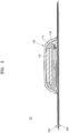
- FIG. 2 illustrates a cross-section of the wearable device 10 taken along a line II-II of FIG. 1
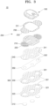
- FIG. 3 is an exploded perspective view of the wearable device 10, according to an embodiment of the disclosure
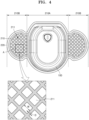
- FIG. 4 is a top view of an electrode unit 200
- FIG. 5 illustrates an electrode pattern layer 220 of an electrode unit
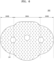
- FIG. 6 is a top view of a patch unit 300.
- the wearable device 10 may be an electronic device that is used by being attached to a user's back, chest, shoulder, arm, or leg.
- the wearable device 10 is attached to the user's skin and measures a biosignal such as an electrocardiogram (ECG), an electromyogram (EMG), or a blood pressure.
- ECG electrocardiogram
- EMG electromyogram
- the wearable device 10 may be a device for measuring an ECG by inputting, by the electrode unit 200, a voltage generated along with a heartbeat.
- the wearable device 10 may be a device for measuring an electroencephalogram (EEG) by inputting, by the electrode unit 200, a voltage generated from cranial nerves.
- ECG electrocardiogram
- EMG electromyogram
- the wearable device 10 may be a device for measuring an EMG by inputting, by the electrode unit 200, a voltage generated from a skeletal muscle.
- the wearable device 10 may be a continuous glucose monitor (CGM) or a transdermal therapeutic device using iontophoresis based on a measured biosignal such as an ECG, an EEG, or an EMG.
- the wearable device 10 may be in a contact switch type using a button or a touch switch type.
- the wearable device 10 may include a circuit for detecting the button press or detecting the touch of an object.
- the wearable device 10 may include a main body unit 100, the electrode unit 200, and the patch unit 300.
- the main body unit 100 is arranged on one side of the wearable device 10 and may include a housing 110, a battery 120, and a substrate 130.
- the main body unit 100 is a component for measuring an ECG while the wearable device 10 is attached to the user's body, and may include a processor, a memory, a display, an indicator, and other support structures.
- specific components will be mainly described for convenience of description, but unless otherwise stated, components not described are not omitted or reduced in the wearable device 10.
- the housing 110 protects other components of the main body unit 100 from an external shock and prevents an external foreign material from being introduced thereinto.
- a shape, a size, and a material of the housing 110 are not particularly limited and may be appropriately selected according to the purpose of use of the wearable device 10.
- the housing 110 may have a dome shape including an internal space.
- a button may be arranged on an upper surface of the housing 110.
- FIG. 1 illustrates that only one power button is arranged on the upper surface of the housing 110, the disclosure is not limited thereto.
- a plurality of buttons for controlling power of the wearable device 10 and controlling an operation mode of the wearable device 10 may be arranged on the upper surface or a side surface of the housing 110.
- the battery 120 and the substrate 130 may be arranged in the internal space of the housing 110.
- the substrate 130 may be supported by a support structure arranged in the internal space of the housing 110, and the battery 120 may be arranged on the substrate 130.
- a signal amplification circuit for the wearable device 10 to operate, a signal processing circuit, a control circuit, a processor, and a memory may be arranged on the substrate 130.
- an antistatic paint may be coated on the inside of the main body unit 100.
- an antistatic paint is coated or applied to the housing 110, so that external static electricity may be prevented from flowing into the main body unit 100 through the housing 110.
- the electrode unit 200 may be arranged on one side of the main body unit 100 and may include a sensing electrode 221 (see FIG. 5 ) connected to the main body unit 100.
- the electrode unit 200 may be connected to the substrate 130 of the main body unit 100, and the sensing electrode 221 may measure a potential appearing in relation to an electrogram on the body surface or apply a current to inject an electrolyte drug into the user's body through his or her skin or mucous membrane.
- the sensing electrode 221 may measure an impedance between electrodes.
- the electrode unit 200 may include a shielding layer 210 and the electrode pattern layer 220.
- the shielding layer 210 may include a conductive material such as a metal, and may be arranged on an upper surface of the electrode unit 200 to prevent an abnormal potential such as external static electricity from being applied to the sensing electrode 221 and affecting a measurement signal.
- the shielding layer 210 may be arranged to cover the electrode pattern layer 220 printed on a rear surface of the electrode unit 200.
- the shielding layer 210 includes a first shielding region 210A and a second shielding region 210B.
- the first shielding region 210A may be arranged at the center of the shielding layer 210 so that the main body unit 100 is arranged inside the first shielding region 210A. Also, when viewed from the top, the first shielding region 210A is spaced apart from an edge of the main body unit 100 by a certain distance, and the main body unit 100 is arranged inside the first shielding region 210A.
- a connection portion of the sensing electrode 221 and the main body unit 100 may be arranged inside the first shielding region 210A. That is, the first shielding region 210A may cover a first sensing electrode terminal 221a of the sensing electrode 221, which will be described below. Also, the first shielding region 210A may cover at least one of a plurality of conductive members 310.
- the second shielding region 210B may extend from both sides of the first shielding region 210A. When viewed from the top, at least one conductive member 310 may be arranged inside the second shielding region 210B. That is, the second shielding region 210B may over at least one of the plurality of conductive members 310.
- the shielding layer 210 may be floating relative to the main body unit 100. That is, the shielding layer 210 and the main body unit 100 may maintain a state not electrically connected to each other. Accordingly, the influence of external static electricity on the main body unit 100 while flowing through the shielding layer 210 may be minimized.
- the shielding layer 210 may include a plurality of third ventilation holes 211 arranged in a certain pattern. For example, as illustrated in FIG. 4 , when the shielding layer 210 is viewed from the top, the plurality of third ventilation holes 211 may be arranged on both sides of the shielding layer 210. That is, the third ventilation holes 211 may be arranged in the second shielding region 210B.
- moisture generated from his or her skin may not flow into the main body unit 100 and may be discharged to the outside through the plurality of third ventilation holes 211.
- a width of a third ventilation hole 211 may be greater than a distance between adjacent third ventilation holes 211.
- a width W of the third ventilation hole 211 may be greater than a distance D between adjacent third ventilation holes 211.
- the width of the third ventilation hole 211 may be sufficiently secured to increase moisture permeability, and static electricity applied from the outside may also flow to the outside through a ground electrode 222 of the electrode pattern layer 220, which will be described below, through a region between the third ventilation holes 211. Therefore, both the moisture permeability and an effect of preventing measurement noise caused by static electricity may be achieved.
- FIG. 4 illustrates that the plurality of third ventilation holes 211 form a mesh structure
- the disclosure is not limited thereto.
- the plurality of third ventilation holes 211 may each have a circular shape, a polygonal shape, or a shape in which a straight line and a curved line are mixed, and may have different sizes and shapes.
- the shielding layer 210 may be printed on the upper surface of the electrode unit 200 with an inductive ink.
- the shielding layer 210 may be in a state in which a certain potential is applied through a separate circuit separated from the main body unit 100 to prevent external static electricity from flowing into the main body unit 100.
- the electrode pattern layer 220 may be arranged on one surface of the electrode unit 200, for example, on the other surface of the electrode unit 200, which is a surface opposite to the shielding layer 210.
- the electrode pattern layer 220 may be printed on the rear surface of the electrode unit 200 and may include a plurality of sensing electrodes 221.
- FIG. 5 illustrates that three sensing electrodes 221 are respectively arranged at the center and both sides of the electrode pattern layer 220 in a longitudinal direction, four or more sensing electrodes 221 or two or less sensing electrodes 221 may be present, and locations of the sensing electrodes 221 are not particularly limited. However, hereinafter, a case in which the wearable device 10 includes three sensing electrodes 221 will be mainly described for convenience of description.
- Each of the sensing electrodes 221 may include a first sensing electrode terminal 221a connected to the main body unit 100 (in more detail, connected to the substrate 130 of the main body unit 100) and a second electrode terminal 221b connected to the conductive member 310 of the patch unit 300, which will be described below.
- the first sensing electrode terminal 221a of the sensing electrode 221 may be arranged at the center of the electrode pattern layer 220 in the longitudinal direction, and one second electrode terminal 221b may be arranged at each of the center and both sides of the electrode pattern layer 220.
- the electrode pattern layer 220 is in contact with the user's skin and is connected to the shielding layer 210, so that external static electricity may flow into the user's skin.
- the electrode pattern layer 220 may further include the ground electrode 222 in addition to the sensing electrodes 221.
- the ground electrode 222 may be in contact with the user's skin and may include a first ground electrode terminal 222a connected to the shielding layer 210 and a second ground electrode terminal 222b connected to the conductive member 310. Also, the ground electrode 222 may not be electrically connected to the main body unit 100 or the first ground electrode terminal 222a may be omitted.
- the electrode pattern layer 220 is connected to the shielding layer 210 and the user's skin so that the user's skin may be used as a kind of ground. Accordingly, when static electricity is generated, energy of the static electricity transmitted from the shielding layer 210 may be grounded to the user's skin. Also, because the ground electrode 222 is not connected to the main body unit 100, external static electricity may be prevented from flowing into the main body unit 100.
- the electrode unit 200 may further include an electrode protection layer 230.
- the electrode protection layer 230 may block external static electricity to prevent static electricity from affecting the measurement precision of the wearable device 10.
- the electrode protection layer 230 may be arranged on the upper surface of the electrode unit 200, that is, on the shielding layer 210.
- the electrode unit 200 may include a conductor (e.g., a structure printed with a metal paint or a metal body), and a portion of the electrode unit 200 may not be electrically connected to the main body unit 100.
- a conductor e.g., a structure printed with a metal paint or a metal body
- the electrode protection layer 230 may have an area greater than those of other components of the electrode unit 200. In more detail, because the electrode protection layer 230 has an area greater than those of the shielding layer 210 and the electrode pattern layer 220, a portion of the wearable device 10 may be in contact with the user's body while the wearable device 10 is attached to the user's body.
- Such a configuration may prevent external static electricity from affecting the main body unit 100 and cause static electricity to be applied to the user's body by using the user's body as a kind of ground electrode.
- the electrode protection layer 230 may include, on the inside thereof, a mounting groove 231 corresponding to a shape of the main body unit 100 and may include, on the outside thereof, a plurality of fourth ventilation holes 232 arranged in a certain pattern.
- the main body unit 100 may be positioned inside the mounting groove 231.
- the mounting groove 231 may be positioned at the center of the electrode protection layer 230 in a longitudinal direction.
- the plurality of fourth ventilation holes 232 may be arranged on both sides of the mounting groove 231, respectively.
- the plurality of fourth ventilation holes 232 may be arranged in the same pattern as the plurality of third ventilation holes 211.
- the same pattern means that sizes of a plurality of ventilation holes and distances therebetween may be slightly different from each other but shapes of the plurality of ventilation holes are the same as rectangular, square, rhombus, or circular shapes.
- the plurality of fourth ventilation holes 232 may be arranged to correspond to the plurality of third ventilation holes 211. That is, the plurality of fourth ventilation holes 232 may have the same size, shape, and location as the plurality of third ventilation holes 211. Also, the plurality of fourth ventilation holes 232 may have irregular shapes with permeability.
- moisture introduced into the electrode unit 200 through the patch unit 300 may be smoothly discharged to the outside through the third ventilation holes 211 and/or the fourth ventilation holes 232.
- the patch unit 300 may be arranged under the electrode unit 200 and may be in direct contact with the user's skin to inject a drug into the user's skin.
- the patch unit 300 may include one or more conductive members 310 for electrically connecting the electrode unit 200 to the user's skin, and may include multiple layers including a plurality of ventilation holes.
- the patch unit 300 may include a main region 300A and a pair of sub-regions 300B extending from both sides of the main region 300A, respectively.
- the main region 300A may be arranged at the center of the patch unit 300 in a longitudinal direction, and the sub-regions 300B may be arranged on both sides of the main region 300A, respectively.
- the conductive members 310 are members in direct contact with the user's skin while the wearable device 10 is attached to the user's skin, and may be electrically connected to the electrode unit 200.
- each of the conductive members 310 may include a biocompatible material and may be hydrogel.
- the conductive members 310 may be in direct contact with the user's skin while being inserted into the patch unit 300 through mounting holes 301 provided in each of the main region 300A and the sub-regions 300B of the patch unit 300 by one.
- the mounting holes 301 may be formed through at least one of a plurality of layers of the patch unit 300 in a height direction.
- the mounting holes 301 may be formed through a first attachment layer 320 and an absorption layer 330 of the patch unit 300, which will be described below.
- the conductive members 310 may be in contact with the electrode unit 200 while being inserted into the mounting holes 301.
- the conductive members 310 may be in contact with the electrode unit 200 while being inserted into the patch unit 300 through contact holes 302 provided in each of the main region 300A and the sub-regions 300B of the patch unit 300 by one.
- the contact holes 302 may be formed through at least one of the plurality of layers of the patch unit 300 in the height direction.
- the contact holes 302 may be formed through a second attachment layer 340 and a current-stopping layer 350 of the patch unit 300, which will be described below.
- the conductive members 310 may be in contact with the electrode unit 200 through the contact holes 302 while being inserted into the mounting holes 301.
- ventilation holes of the patch unit 300 may be arranged in at least one of the main region 300A and the sub-regions 300B except for a region in which the mounting holes 301 and/or the contact holes 302 are formed.
- the patch unit 300 may include the first attachment layer 320, the absorption layer 330, the second attachment layer 340, and the current-stopping layer 350.
- the first attachment layer 320 is a member in direct contact with the user's skin and may be an adhesive member for fixing the patch unit 300 to the user's skin.
- the first attachment layer 320 is a tape including a biocompatible material and may be a silicon tape.
- the first attachment layer 320 may include a plurality of first ventilation holes 321.
- the first ventilation holes 321 may be randomly arranged on the entire surface of the first attachment layer 320 in a remaining region except for the mounting holes 301. Accordingly, sweat generated on the user's skin may be discharged to the outside through the first attachment layer 320 without staying in the first attachment layer 320 for a long time.
- the absorption layer 330 may be arranged on the first attachment layer 320 and may include a material capable of retaining moisture so that the sweat generated on the user's skin or external moisture does not flow into the main body unit 100 or the electrode unit 200.
- the absorption layer 330 may be a fibrous layer, and more particularly, may include a non-woven fabric and may re-discharge retained moisture.
- the second attachment layer 340 is a member for attaching the patch unit 300 to the electrode unit 200, may be arranged on the absorption layer 330 to connect the electrode unit 200 to the patch unit 300, and may include a plurality of second ventilation holes 341.
- An adhesive material may be coated on both sides of the second attachment layer 340, and the second attachment layer 340 may be a double-sided tape.
- the plurality of second ventilation holes 341 may be arranged to communicate with the plurality of first ventilation holes 321 in a height direction. That is, the plurality of second ventilation holes 341 may be arranged at positions corresponding to the plurality of first ventilation holes 321. Alternatively, the plurality of second ventilation holes 341 may be arranged in the same pattern as the plurality of first ventilation holes 321. Alternatively, the plurality of second ventilation holes 341 may be arranged with the same size, shape, and number as the plurality of first ventilation holes 321.
- the patch unit 300 may further include current-stopping layer 350.
- the current-stopping layer 350 may be between the absorption layer 330 and the second attachment layer 340 and may prevent current flowing between other members of the wearable device 10 or prevent fine current application between the wearable device 10 and the user's skin.
- the current-stopping layer 350 may include a moisture-permeable material and may be a moisture-permeable polyurethane tape.
- the current-stopping layer 350 may also include ventilation holes, and the ventilation holes may be arranged to communicate with ventilation holes of the first attachment layer 320, the absorption layer 330, and the second attachment layer 340.
- the ventilation holes of the current-stopping layer 350 may be arranged with the same number, pattern, and shape as the ventilation holes of the first attachment layer 320, the absorption layer 330, and the second attachment layer 340.
- the patch unit 300 may be simplified by using the same function or different materials.
- FIG. 7 illustrates a wearable device 10A according to another embodiment of the disclosure.
- the wearable device 10A may further include a fixing unit 400.
- the fixing unit 400 includes an accommodation groove 410 in which the main body unit 100 is accommodated, and both side regions of the accommodation groove 410 covers the upper surface of the electrode unit 200.
- the fixing unit 400 may have an area greater than those of the electrode unit 200 and/or the patch unit 300. In more detail, as illustrated in FIG. 7 , at least a portion of the fixing unit 400 may protrude to the outside of the electrode unit 200 and/or the patch unit 300 to adhere to the user's skin while the fixing unit 400 is arranged on the electrode unit 200.
- the fixing unit 400 may include a moisture-permeable material.
- the fixing unit 400 may include a material having moisture directionality, such as a moisture-permeable polyurethane tape or Gore-Tex.
- the fixing unit 400 may include a waterproof material. Accordingly, the fixing unit 400 may prevent external moisture from flowing into the inside of the wearable device 10A (waterproofness) and may discharge internal moisture to the outside (moisture permeability).
- the method of manufacturing the wearable device may manufacture a wearable device 10 used by being attached to a user's skin, by assembling a patch unit 300 by stacking a plurality of layers, and stacking the assembled patch unit 300, an electrode unit 200, and a main body unit 100. Also, according to an embodiment of the disclosure, the method of manufacturing the wearable device may form a plurality of ventilation holes in the patch unit 300 by blanking the plurality of stacked layers by using a press tool.
- the patch unit 300 is assembled by stacking the plurality of layers.
- the patch unit 300 is assembled by stacking a first attachment layer 320, an absorption layer 330, a second attachment layer 340, and a current-stopping layer 350.
- the electrode unit 200 is assembled by assembling and stacking a plurality of members in a similar manner.
- the electrode unit 200 may be assembled by forming a shielding layer 210 and an electrode pattern layer 220 in the electrode unit 200, and then arranging an electrode protection layer 230 on the shielding layer 210.
- an order of assembling the electrode unit 200 and the patch unit 300 is not particularly limited, and the electrode unit 200 may be assembled first or the electrode unit 200 and the patch unit 300 may be assembled simultaneously.
- ventilation holes are formed in the patch unit 300 by performing a blanking process by using the press tool.
- the plurality of ventilation holes may be formed in the patch unit 300 by blanking the patch unit 300, in which the plurality of layers, such as the first attachment layer 320, the absorption layer 330, the second attachment layer 340, and the current-stopping layer 350, are stacked, by using the press tool.
- the wearable device 10 is manufactured by stacking the blanked patch unit 300, the electrode unit 200, and the main body unit 100.
- ventilation holes are formed by blanking the shielding layer 210 and the electrode protection layer 230 by using the press tool, and then, the electrode unit 200 may be assembled.
- the shielding layer 210 and the electrode protection layer 230 may be blanked while the shielding layer 210 and the electrode protection layer 230 are stacked, or the shielding layer 210 and the electrode protection layer 230 may be blanked separately.
- a blanking process may be performed on each member first before the patch unit 300 is stacked. That is, a blanking process may be performed by using different press tools for each of the first attachment layer 320, the absorption layer 330, the second attachment layer 340, and the current-stopping layer 350 of the patch unit 300.
- the patch unit 300 may be assembled by stacking the first attachment layer 320, the absorption layer 330, the second attachment layer 340, and the current-stopping layer 350.
- the wearable device has a structure for preventing noise caused by static electricity, the structure preventing external static electricity from affecting a main body unit, and thus, the measurement precision of the wearable device may be prevented from deteriorating due to external static electricity.
Landscapes
- Health & Medical Sciences (AREA)
- Life Sciences & Earth Sciences (AREA)
- Engineering & Computer Science (AREA)
- Physics & Mathematics (AREA)
- Animal Behavior & Ethology (AREA)
- Veterinary Medicine (AREA)
- Public Health (AREA)
- General Health & Medical Sciences (AREA)
- Biomedical Technology (AREA)
- Pathology (AREA)
- Medical Informatics (AREA)
- Molecular Biology (AREA)
- Surgery (AREA)
- Heart & Thoracic Surgery (AREA)
- Biophysics (AREA)
- Microelectronics & Electronic Packaging (AREA)
- Electromagnetism (AREA)
- Radiology & Medical Imaging (AREA)
- Nuclear Medicine, Radiotherapy & Molecular Imaging (AREA)
- Cardiology (AREA)
- Measurement And Recording Of Electrical Phenomena And Electrical Characteristics Of The Living Body (AREA)
- Signal Processing (AREA)
- Artificial Intelligence (AREA)
- Computer Vision & Pattern Recognition (AREA)
- Physiology (AREA)
- Psychiatry (AREA)
- Chemical & Material Sciences (AREA)
- Dispersion Chemistry (AREA)
Claims (9)
- Tragbare Vorrichtung (10), die durch Befestigung an der Haut eines Benutzers verwendet wird, wobei die tragbare Vorrichtung (10) aufweist:- eine Hauptkörpereinheit (100), die ein Gehäuse (110) und ein Substrat (130) umfasst, wobei das Substrat (130) innerhalb des Gehäuses (110) angeordnet ist;- eine Elektrodeneinheit (200), die eine mit der Hauptkörpereinheit (100) verbundene Sensorelektrode (221) umfasst; und- eine Patch-Einheit (300) mit einem oder mehreren leitfähigen Elementen (310), wobei die ein oder mehrere leitfähigen Elemente (310) eingerichtet sind, um die Elektrodeneinheit (200) elektrisch mit der Haut des Benutzers zu verbinden,- wobei die Elektrodeneinheit (200) eine Abschirmschicht (210) umfasst, die nicht elektrisch mit der Hauptkörpereinheit (100) verbunden ist, wobei die Abschirmschicht (210) mit einem schwebenden Potential leitfähig ist, und- wobei die Abschirmschicht (210) einen ersten Abschirmbereich (210A) und einen zweiten Abschirmbereich (210B) umfasst und, bei Betrachtung von oben, der erste Abschirmbereich (210A) um einen bestimmten Abstand von einer Kante der Hauptkörpereinheit (100) getrennt ist, und dadurch gekennzeichnet, dass die Hauptkörpereinheit (100) innerhalb des ersten Abschirmbereichs (210A) angeordnet ist.
- Tragbare Vorrichtung (10) nach Anspruch 1, wobei sich die Abschirmschicht (210) auf einer oberen Fläche der Elektrodeneinheit (100) befindet, um eine auf eine hintere Fläche der Elektrodeneinheit (210) gedruckte Elektrodenmusterschicht (220) abzudecken.
- Tragbare Vorrichtung (10) nach Anspruch 1, wobei sich der zweite Abschirmbereich (210B) von beiden Seiten des ersten Abschirmbereichs (210A) erstreckt.
- Tragbare Vorrichtung (10) gemäß Anspruch 3, wobei, bei Betrachtung von oben, ein Verbindungsabschnitt der Sensorelektrode (221) und der Hauptkörpereinheit (100) innerhalb des ersten Abschirmbereichs (210A) angeordnet ist und ein oder mehrere leitfähigen Elemente (310) innerhalb des zweiten Abschirmbereichs (210B) angeordnet sind.
- Tragbare Vorrichtung (10) nach Anspruch 3, wobei der zweite Abschirmbereich (210B) eine Maschenstruktur aufweist.
- Tragbare Vorrichtung (10) nach Anspruch 1, wobei die Abschirmschicht (210) auf eine obere Fläche der Elektrodeneinheit (200) mit einer induktiven Tinte gedruckt ist.
- Tragbare Vorrichtung (10) nach Anspruch 1, wobei ein bestimmtes Potenzial über einen separaten Schaltkreis, der von der Hauptkörpereinheit (100) getrennt ist, an die Abschirmschicht (210) angelegt wird, so dass keine externe statische Elektrizität in die Hauptkörpereinheit (100) fließt.
- Tragbare Vorrichtung (10) gemäß Anspruch 1, wobei die Elektrodeneinheit (100) ferner eine Elektrodenmusterschicht (220) umfasst, die auf eine hintere Fläche der Elektrodeneinheit (210) gedruckt ist, mit der Haut des Benutzers über das eine oder mehrere leitfähige Elemente (310) in Kontakt steht und mit der Abschirmschicht (210) verbunden ist, um einen Fließen von externer statischer Elektrizität in die Haut des Benutzers zu bewirken.
- Tragbare Vorrichtung nach Anspruch 1, wobei die Abschirmschicht (210) eine Elektrode umfasst, die nicht elektrisch mit der Hauptkörpereinheit (100) verbunden ist und mit der Haut des Benutzers verbunden ist.
Applications Claiming Priority (1)
| Application Number | Priority Date | Filing Date | Title |
|---|---|---|---|
| KR1020210087857A KR102360815B1 (ko) | 2021-07-05 | 2021-07-05 | 정전기로 인한 노이즈 방지 구조를 구비하는 웨어러블 디바이스 |
Publications (2)
| Publication Number | Publication Date |
|---|---|
| EP4115809A1 EP4115809A1 (de) | 2023-01-11 |
| EP4115809B1 true EP4115809B1 (de) | 2025-05-07 |
Family
ID=80254103
Family Applications (1)
| Application Number | Title | Priority Date | Filing Date |
|---|---|---|---|
| EP22167180.3A Active EP4115809B1 (de) | 2021-07-05 | 2022-04-07 | Am körper tragbare vorrichtung mit einer struktur zur verhinderung von durch statische elektrizität verursachte störungen |
Country Status (3)
| Country | Link |
|---|---|
| US (1) | US12303276B2 (de) |
| EP (1) | EP4115809B1 (de) |
| KR (1) | KR102360815B1 (de) |
Families Citing this family (1)
| Publication number | Priority date | Publication date | Assignee | Title |
|---|---|---|---|---|
| USD1048908S1 (en) * | 2022-10-04 | 2024-10-29 | Masimo Corporation | Wearable sensor |
Citations (1)
| Publication number | Priority date | Publication date | Assignee | Title |
|---|---|---|---|---|
| US20150223716A1 (en) * | 2013-05-15 | 2015-08-13 | Polar Electro Oy | Heart activity sensor structure |
Family Cites Families (11)
| Publication number | Priority date | Publication date | Assignee | Title |
|---|---|---|---|---|
| NO330410B1 (no) | 2007-10-09 | 2011-04-11 | Wireless Patient Recording Medical As | Anordning ved elektrodedel for tradlos biopotensialemaleenhet |
| KR101002020B1 (ko) | 2008-03-27 | 2010-12-16 | 계명대학교 산학협력단 | 실시간 심전도 모니터링 시스템 및 방법, 패치형 심전도측정장치, 통신장치 |
| US9901273B2 (en) * | 2012-07-04 | 2018-02-27 | I Medex Co., Ltd. | Bioelectrode |
| AU2014209376B2 (en) * | 2013-01-24 | 2017-03-16 | Irhythm Technologies, Inc. | Physiological monitoring device |
| US20180368769A1 (en) | 2014-07-01 | 2018-12-27 | Nikomed Usa Inc. | Printed Conductive Leads for Medical Applications |
| US9918669B2 (en) * | 2014-08-08 | 2018-03-20 | Medtronic Xomed, Inc. | Wireless nerve integrity monitoring systems and devices |
| KR101868688B1 (ko) | 2016-08-08 | 2018-06-18 | 박지만 | 생체 신호 측정 방법 및 장치 |
| KR20180061819A (ko) | 2016-11-30 | 2018-06-08 | 주식회사 베프스 | 다중 생체 인증 장치 또는 다중 생체 인증 시스템, 그리고 이를 사용한 다중 생체 인증 방법 |
| KR101784736B1 (ko) | 2017-05-29 | 2017-10-12 | 주식회사 중일산업 | 압전 센서 |
| KR20200113861A (ko) * | 2019-03-26 | 2020-10-07 | 주식회사 이큐브머티리얼즈 | 생체 신호 측정 전극용 전도성 실리콘 점착 패드 |
| KR20200113819A (ko) | 2019-03-26 | 2020-10-07 | 주식회사 이큐브머티리얼즈 | 생체 신호 측정용 전극 |
-
2021
- 2021-07-05 KR KR1020210087857A patent/KR102360815B1/ko active Active
-
2022
- 2022-04-06 US US17/714,649 patent/US12303276B2/en active Active
- 2022-04-07 EP EP22167180.3A patent/EP4115809B1/de active Active
Patent Citations (1)
| Publication number | Priority date | Publication date | Assignee | Title |
|---|---|---|---|---|
| US20150223716A1 (en) * | 2013-05-15 | 2015-08-13 | Polar Electro Oy | Heart activity sensor structure |
Also Published As
| Publication number | Publication date |
|---|---|
| KR102360815B1 (ko) | 2022-02-14 |
| US12303276B2 (en) | 2025-05-20 |
| US20230000414A1 (en) | 2023-01-05 |
| EP4115809A1 (de) | 2023-01-11 |
| KR102360815B9 (ko) | 2023-03-03 |
Similar Documents
| Publication | Publication Date | Title |
|---|---|---|
| US12551692B2 (en) | Garments for wearable medical devices | |
| US9901273B2 (en) | Bioelectrode | |
| EP2164389B1 (de) | Abgeschirmte biomedizinische elektrodenfläche | |
| US8560040B2 (en) | Shielded biomedical electrode patch | |
| EP4115808B1 (de) | Tragbare vorrichtung, die eine feuchtigkeitsdurchlässige struktur umfasst, und verfahren zur herstellung derselben | |
| EP2848195B1 (de) | Wegwerfbare Kontaktschutzauflagenabdeckung für biomedizinische Sensoren | |
| US12303276B2 (en) | Wearable device including structure for preventing noise caused by static electricity | |
| EP3914152B1 (de) | Elastischer tragbarer sensor | |
| US10881305B2 (en) | Wearable thoracic element for detecting, monitoring and reporting the physiological status of an individual | |
| US12201430B2 (en) | Wearable device having structure preventing measurement error caused by impedance | |
| US20250247949A1 (en) | Wearable device including structure for preventing noise caused by static electricity | |
| KR20260027696A (ko) | 웨어러블 디바이스 및 웨어러블 디바이스를 이용한 생체신호 측정방법 | |
| EP4236802B1 (de) | Sensormatrix und sensormatrixsystem zur messung elektrischer aktivität | |
| CN117322886A (zh) | 心电监测系统 | |
| HK40063865A (en) | Elastic wearable sensor | |
| HK40063865B (en) | Elastic wearable sensor | |
| PL248787B1 (pl) | Elektrokardiograficzne urządzenie naramienne i sposób pomiaru sygnału elektrokardiograficznego |
Legal Events
| Date | Code | Title | Description |
|---|---|---|---|
| PUAI | Public reference made under article 153(3) epc to a published international application that has entered the european phase |
Free format text: ORIGINAL CODE: 0009012 |
|
| STAA | Information on the status of an ep patent application or granted ep patent |
Free format text: STATUS: REQUEST FOR EXAMINATION WAS MADE |
|
| 17P | Request for examination filed |
Effective date: 20220407 |
|
| AK | Designated contracting states |
Kind code of ref document: A1 Designated state(s): AL AT BE BG CH CY CZ DE DK EE ES FI FR GB GR HR HU IE IS IT LI LT LU LV MC MK MT NL NO PL PT RO RS SE SI SK SM TR |
|
| GRAP | Despatch of communication of intention to grant a patent |
Free format text: ORIGINAL CODE: EPIDOSNIGR1 |
|
| STAA | Information on the status of an ep patent application or granted ep patent |
Free format text: STATUS: GRANT OF PATENT IS INTENDED |
|
| RIC1 | Information provided on ipc code assigned before grant |
Ipc: A61B 5/145 20060101ALN20241018BHEP Ipc: A61B 5/021 20060101ALN20241018BHEP Ipc: A61N 1/04 20060101ALI20241018BHEP Ipc: A61B 5/296 20210101ALI20241018BHEP Ipc: A61B 5/291 20210101ALI20241018BHEP Ipc: A61B 5/282 20210101ALI20241018BHEP Ipc: A61B 5/257 20210101AFI20241018BHEP |
|
| RIC1 | Information provided on ipc code assigned before grant |
Ipc: A61B 5/145 20060101ALN20241112BHEP Ipc: A61B 5/021 20060101ALN20241112BHEP Ipc: A61N 1/04 20060101ALI20241112BHEP Ipc: A61B 5/296 20210101ALI20241112BHEP Ipc: A61B 5/291 20210101ALI20241112BHEP Ipc: A61B 5/282 20210101ALI20241112BHEP Ipc: A61B 5/257 20210101AFI20241112BHEP |
|
| INTG | Intention to grant announced |
Effective date: 20241127 |
|
| RIN1 | Information on inventor provided before grant (corrected) |
Inventor name: KIM, JONG SUNG Inventor name: JEONG, JONG OOK Inventor name: CHO, SEUNG BUM Inventor name: PARK, SOON KEUN |
|
| RIN1 | Information on inventor provided before grant (corrected) |
Inventor name: KIM, JONG SUNG Inventor name: JEONG, JONG OOK Inventor name: CHO, SEUNG BUM Inventor name: PARK, SOON KEUN |
|
| GRAS | Grant fee paid |
Free format text: ORIGINAL CODE: EPIDOSNIGR3 |
|
| GRAA | (expected) grant |
Free format text: ORIGINAL CODE: 0009210 |
|
| STAA | Information on the status of an ep patent application or granted ep patent |
Free format text: STATUS: THE PATENT HAS BEEN GRANTED |
|
| AK | Designated contracting states |
Kind code of ref document: B1 Designated state(s): AL AT BE BG CH CY CZ DE DK EE ES FI FR GB GR HR HU IE IS IT LI LT LU LV MC MK MT NL NO PL PT RO RS SE SI SK SM TR |
|
| REG | Reference to a national code |
Ref country code: GB Ref legal event code: FG4D |
|
| RIN1 | Information on inventor provided before grant (corrected) |
Inventor name: KIM, JONG SUNG Inventor name: JEONG, JONG OOK Inventor name: CHO, SEUNG BUM Inventor name: PARK, SOON KEUN |
|
| REG | Reference to a national code |
Ref country code: CH Ref legal event code: EP |
|
| REG | Reference to a national code |
Ref country code: DE Ref legal event code: R096 Ref document number: 602022014113 Country of ref document: DE |
|
| REG | Reference to a national code |
Ref country code: IE Ref legal event code: FG4D |
|
| REG | Reference to a national code |
Ref country code: NL Ref legal event code: MP Effective date: 20250507 |
|
| PG25 | Lapsed in a contracting state [announced via postgrant information from national office to epo] |
Ref country code: FI Free format text: LAPSE BECAUSE OF FAILURE TO SUBMIT A TRANSLATION OF THE DESCRIPTION OR TO PAY THE FEE WITHIN THE PRESCRIBED TIME-LIMIT Effective date: 20250507 Ref country code: PT Free format text: LAPSE BECAUSE OF FAILURE TO SUBMIT A TRANSLATION OF THE DESCRIPTION OR TO PAY THE FEE WITHIN THE PRESCRIBED TIME-LIMIT Effective date: 20250908 Ref country code: ES Free format text: LAPSE BECAUSE OF FAILURE TO SUBMIT A TRANSLATION OF THE DESCRIPTION OR TO PAY THE FEE WITHIN THE PRESCRIBED TIME-LIMIT Effective date: 20250507 |
|
| REG | Reference to a national code |
Ref country code: LT Ref legal event code: MG9D |
|
| PG25 | Lapsed in a contracting state [announced via postgrant information from national office to epo] |
Ref country code: NO Free format text: LAPSE BECAUSE OF FAILURE TO SUBMIT A TRANSLATION OF THE DESCRIPTION OR TO PAY THE FEE WITHIN THE PRESCRIBED TIME-LIMIT Effective date: 20250807 Ref country code: GR Free format text: LAPSE BECAUSE OF FAILURE TO SUBMIT A TRANSLATION OF THE DESCRIPTION OR TO PAY THE FEE WITHIN THE PRESCRIBED TIME-LIMIT Effective date: 20250808 |
|
| PG25 | Lapsed in a contracting state [announced via postgrant information from national office to epo] |
Ref country code: NL Free format text: LAPSE BECAUSE OF FAILURE TO SUBMIT A TRANSLATION OF THE DESCRIPTION OR TO PAY THE FEE WITHIN THE PRESCRIBED TIME-LIMIT Effective date: 20250507 Ref country code: PL Free format text: LAPSE BECAUSE OF FAILURE TO SUBMIT A TRANSLATION OF THE DESCRIPTION OR TO PAY THE FEE WITHIN THE PRESCRIBED TIME-LIMIT Effective date: 20250507 |
|
| REG | Reference to a national code |
Ref country code: AT Ref legal event code: MK05 Ref document number: 1791548 Country of ref document: AT Kind code of ref document: T Effective date: 20250507 |
|
| PG25 | Lapsed in a contracting state [announced via postgrant information from national office to epo] |
Ref country code: BG Free format text: LAPSE BECAUSE OF FAILURE TO SUBMIT A TRANSLATION OF THE DESCRIPTION OR TO PAY THE FEE WITHIN THE PRESCRIBED TIME-LIMIT Effective date: 20250507 |
|
| PG25 | Lapsed in a contracting state [announced via postgrant information from national office to epo] |
Ref country code: HR Free format text: LAPSE BECAUSE OF FAILURE TO SUBMIT A TRANSLATION OF THE DESCRIPTION OR TO PAY THE FEE WITHIN THE PRESCRIBED TIME-LIMIT Effective date: 20250507 |
|
| PG25 | Lapsed in a contracting state [announced via postgrant information from national office to epo] |
Ref country code: AT Free format text: LAPSE BECAUSE OF FAILURE TO SUBMIT A TRANSLATION OF THE DESCRIPTION OR TO PAY THE FEE WITHIN THE PRESCRIBED TIME-LIMIT Effective date: 20250507 |
|
| PG25 | Lapsed in a contracting state [announced via postgrant information from national office to epo] |
Ref country code: RS Free format text: LAPSE BECAUSE OF FAILURE TO SUBMIT A TRANSLATION OF THE DESCRIPTION OR TO PAY THE FEE WITHIN THE PRESCRIBED TIME-LIMIT Effective date: 20250807 |
|
| PG25 | Lapsed in a contracting state [announced via postgrant information from national office to epo] |
Ref country code: IS Free format text: LAPSE BECAUSE OF FAILURE TO SUBMIT A TRANSLATION OF THE DESCRIPTION OR TO PAY THE FEE WITHIN THE PRESCRIBED TIME-LIMIT Effective date: 20250907 |
|
| PG25 | Lapsed in a contracting state [announced via postgrant information from national office to epo] |
Ref country code: LV Free format text: LAPSE BECAUSE OF FAILURE TO SUBMIT A TRANSLATION OF THE DESCRIPTION OR TO PAY THE FEE WITHIN THE PRESCRIBED TIME-LIMIT Effective date: 20250507 |
|
| PG25 | Lapsed in a contracting state [announced via postgrant information from national office to epo] |
Ref country code: SM Free format text: LAPSE BECAUSE OF FAILURE TO SUBMIT A TRANSLATION OF THE DESCRIPTION OR TO PAY THE FEE WITHIN THE PRESCRIBED TIME-LIMIT Effective date: 20250507 Ref country code: DK Free format text: LAPSE BECAUSE OF FAILURE TO SUBMIT A TRANSLATION OF THE DESCRIPTION OR TO PAY THE FEE WITHIN THE PRESCRIBED TIME-LIMIT Effective date: 20250507 |
|
| PG25 | Lapsed in a contracting state [announced via postgrant information from national office to epo] |
Ref country code: CZ Free format text: LAPSE BECAUSE OF FAILURE TO SUBMIT A TRANSLATION OF THE DESCRIPTION OR TO PAY THE FEE WITHIN THE PRESCRIBED TIME-LIMIT Effective date: 20250507 |
|
| PG25 | Lapsed in a contracting state [announced via postgrant information from national office to epo] |
Ref country code: EE Free format text: LAPSE BECAUSE OF FAILURE TO SUBMIT A TRANSLATION OF THE DESCRIPTION OR TO PAY THE FEE WITHIN THE PRESCRIBED TIME-LIMIT Effective date: 20250507 |
|
| PG25 | Lapsed in a contracting state [announced via postgrant information from national office to epo] |
Ref country code: SK Free format text: LAPSE BECAUSE OF FAILURE TO SUBMIT A TRANSLATION OF THE DESCRIPTION OR TO PAY THE FEE WITHIN THE PRESCRIBED TIME-LIMIT Effective date: 20250507 |
|
| PG25 | Lapsed in a contracting state [announced via postgrant information from national office to epo] |
Ref country code: IT Free format text: LAPSE BECAUSE OF FAILURE TO SUBMIT A TRANSLATION OF THE DESCRIPTION OR TO PAY THE FEE WITHIN THE PRESCRIBED TIME-LIMIT Effective date: 20250507 |
|
| REG | Reference to a national code |
Ref country code: DE Ref legal event code: R097 Ref document number: 602022014113 Country of ref document: DE |
|
| PLBE | No opposition filed within time limit |
Free format text: ORIGINAL CODE: 0009261 |
|
| STAA | Information on the status of an ep patent application or granted ep patent |
Free format text: STATUS: NO OPPOSITION FILED WITHIN TIME LIMIT |
|
| REG | Reference to a national code |
Ref country code: CH Ref legal event code: L10 Free format text: ST27 STATUS EVENT CODE: U-0-0-L10-L00 (AS PROVIDED BY THE NATIONAL OFFICE) Effective date: 20260318 |
|
| 26N | No opposition filed |
Effective date: 20260210 |