EP4115384B1 - Auflösungsverbesserung bei dualer energie - Google Patents
Auflösungsverbesserung bei dualer energie Download PDFInfo
- Publication number
- EP4115384B1 EP4115384B1 EP21710041.1A EP21710041A EP4115384B1 EP 4115384 B1 EP4115384 B1 EP 4115384B1 EP 21710041 A EP21710041 A EP 21710041A EP 4115384 B1 EP4115384 B1 EP 4115384B1
- Authority
- EP
- European Patent Office
- Prior art keywords
- inspection
- data
- pixel intensity
- energy mode
- intensity values
- Prior art date
- Legal status (The legal status is an assumption and is not a legal conclusion. Google has not performed a legal analysis and makes no representation as to the accuracy of the status listed.)
- Active
Links
Images

Classifications
-
- G—PHYSICS
- G06—COMPUTING OR CALCULATING; COUNTING
- G06T—IMAGE DATA PROCESSING OR GENERATION, IN GENERAL
- G06T7/00—Image analysis
- G06T7/0002—Inspection of images, e.g. flaw detection
- G06T7/0004—Industrial image inspection
-
- G—PHYSICS
- G01—MEASURING; TESTING
- G01V—GEOPHYSICS; GRAVITATIONAL MEASUREMENTS; DETECTING MASSES OR OBJECTS; TAGS
- G01V5/00—Prospecting or detecting by the use of ionising radiation, e.g. of natural or induced radioactivity
- G01V5/20—Detecting prohibited goods, e.g. weapons, explosives, hazardous substances, contraband or smuggled objects
- G01V5/22—Active interrogation, i.e. by irradiating objects or goods using external radiation sources, e.g. using gamma rays or cosmic rays
- G01V5/224—Multiple energy techniques using one type of radiation, e.g. X-rays of different energies
-
- G—PHYSICS
- G06—COMPUTING OR CALCULATING; COUNTING
- G06T—IMAGE DATA PROCESSING OR GENERATION, IN GENERAL
- G06T5/00—Image enhancement or restoration
- G06T5/40—Image enhancement or restoration using histogram techniques
-
- G—PHYSICS
- G06—COMPUTING OR CALCULATING; COUNTING
- G06T—IMAGE DATA PROCESSING OR GENERATION, IN GENERAL
- G06T5/00—Image enhancement or restoration
- G06T5/90—Dynamic range modification of images or parts thereof
- G06T5/92—Dynamic range modification of images or parts thereof based on global image properties
-
- G—PHYSICS
- G06—COMPUTING OR CALCULATING; COUNTING
- G06T—IMAGE DATA PROCESSING OR GENERATION, IN GENERAL
- G06T7/00—Image analysis
- G06T7/0002—Inspection of images, e.g. flaw detection
-
- G—PHYSICS
- G06—COMPUTING OR CALCULATING; COUNTING
- G06V—IMAGE OR VIDEO RECOGNITION OR UNDERSTANDING
- G06V10/00—Arrangements for image or video recognition or understanding
- G06V10/40—Extraction of image or video features
- G06V10/50—Extraction of image or video features by performing operations within image blocks; by using histograms, e.g. histogram of oriented gradients [HoG]; by summing image-intensity values; Projection analysis
- G06V10/507—Summing image-intensity values; Histogram projection analysis
-
- H—ELECTRICITY
- H04—ELECTRIC COMMUNICATION TECHNIQUE
- H04N—PICTORIAL COMMUNICATION, e.g. TELEVISION
- H04N25/00—Circuitry of solid-state image sensors [SSIS]; Control thereof
- H04N25/40—Extracting pixel data from image sensors by controlling scanning circuits, e.g. by modifying the number of pixels sampled or to be sampled
- H04N25/46—Extracting pixel data from image sensors by controlling scanning circuits, e.g. by modifying the number of pixels sampled or to be sampled by combining or binning pixels
-
- G—PHYSICS
- G06—COMPUTING OR CALCULATING; COUNTING
- G06T—IMAGE DATA PROCESSING OR GENERATION, IN GENERAL
- G06T2207/00—Indexing scheme for image analysis or image enhancement
- G06T2207/10—Image acquisition modality
- G06T2207/10116—X-ray image
-
- G—PHYSICS
- G06—COMPUTING OR CALCULATING; COUNTING
- G06T—IMAGE DATA PROCESSING OR GENERATION, IN GENERAL
- G06T2207/00—Indexing scheme for image analysis or image enhancement
- G06T2207/20—Special algorithmic details
- G06T2207/20212—Image combination
- G06T2207/20216—Image averaging
-
- G—PHYSICS
- G06—COMPUTING OR CALCULATING; COUNTING
- G06T—IMAGE DATA PROCESSING OR GENERATION, IN GENERAL
- G06T2207/00—Indexing scheme for image analysis or image enhancement
- G06T2207/20—Special algorithmic details
- G06T2207/20212—Image combination
- G06T2207/20221—Image fusion; Image merging
-
- G—PHYSICS
- G06—COMPUTING OR CALCULATING; COUNTING
- G06T—IMAGE DATA PROCESSING OR GENERATION, IN GENERAL
- G06T2207/00—Indexing scheme for image analysis or image enhancement
- G06T2207/30—Subject of image; Context of image processing
- G06T2207/30108—Industrial image inspection
- G06T2207/30112—Baggage; Luggage; Suitcase
Definitions
- the invention relates but is not limited to methods for processing inspection data associated with cargo irradiated by a plurality of pulses of inspection radiation.
- the invention also relates to associated devices and computer program products.
- Some accelerators have a dual energy mode, for example for use for material discrimination.
- the accelerators are used to irradiate cargo with a lower energy mode and with a higher energy mode. Transmission levels of the modes are different for a given cargo, and the material of the cargo may be determined.
- US 2014/233692 discloses multi energy x-ray microscope data acquisition and reconstruction technique.
- Embodiments of the disclosure enable to use the transformed intensities in combination with available intensities associated with the higher energy mode data. Alternatively or additionally, embodiments of the disclosure may enable to effectively double acquisition frequency during inspection. Alternatively or additionally, embodiments of the disclosure may enable to double image resolution in a direction of scanning during inspection. Alternatively or additionally, embodiments of the disclosure enable to improve quality of the inspection image by using the combined intensities. Alternatively or additionally, embodiments of the disclosure enable faster scans during inspection.
- embodiments of the disclosure enable to generate the transformation table using the inspection data obtained from the inspection of the cargo itself.
- embodiments of the disclosure enable the transformation table to remain accurate, even if, for the cargo, the inspection radiation changes, due for example to inspection system aging, radiation source energy variation, detectors replacement, addition of a filter, etc.
- embodiments of the disclosure may enable avoiding a need for a calibration using calibration devices of different materials and/or thicknesses to generate transformation tables.
- embodiments of the disclosure may enable to improve reliability of the generated transformation table.
- Figure 1 schematically represents a flowchart of an example method 100 according to the disclosure.
- the method 100 of Figure 1 may be used for processing inspection data associated with cargo irradiated by a plurality N of pulses of inspection radiation.
- the inspection data may be representative of intensity values of pixels of an inspection image of the cargo.
- the inspection image may be generated as a result of a plurality of detectors detecting the plurality N of pulses transmitted through the cargo.
- the inspection data comprises data associated with a higher energy mode, and data associated with a lower energy mode.
- the data associated with the higher energy mode comprises data generated using a pulse of a higher energy mode (e.g. by a radiation source generating the pulses of inspection radiation), and the data associated with the lower energy mode comprises data generated using a pulse of a lower energy mode.
- the radiation source may be configured to generate pulses with a lower energy, such as an energy of substantially 4 MeV, and pulses with a higher energy, such as an energy of substantially 6 MeV. Other values of energy for each of the modes may be envisaged.
- the plurality N of pulses comprises duplets of inspection radiation, each duplet of inspection radiation comprising a pulse of higher energy mode, and a pulse of lower energy mode.
- the radiation source may be configured to generate the pulses with a lower energy and higher energy alternately, i.e. a pulse of lower energy following a pulse of higher energy, and vice versa.
- the radiation source may be configured to generate the pulses with a lower energy and higher energy following a sequence different from an alternate sequence, i.e. two pulses of higher energy following each other before and after a pulse of lower energy. Other sequences of pulses of higher energy and lower energy may be envisaged.
- the data associated with the higher energy mode comprises data generated using a detector comprising a higher energy mode
- the data associated with the lower energy mode comprises data generated using a detector comprising a lower energy mode
- the radiation source may be configured to generate pulses with a given energy, such as an energy of comprised between 4 MeV-6 MeV (other values of energy for the given energy may be envisaged), and each pulse with given higher energy is detected by two detectors, i.e. both the detector comprising a higher energy mode and the detector comprising a lower energy mode.
- the method 100 of Figure 1 comprises obtaining, at S1, the inspection data.
- the method 100 also comprises generating, at S3, a histogram.
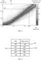
- Figure 2 schematically represents an example histogram 200 according to the disclosure.
- the histogram of Figure 2 has
- generating at S2 the histogram 200 comprises binning, for each pixel (i,j) of the inspection image corresponding to each pulse i and each detector j of the plurality of detectors, an occurrence in the obtained inspection data such that: HM i j ; LM i ⁇ 1 , j + LM i + 1 , j 2 .
- a thickness of the inspected cargo with respect to transmission of pulses is assumed to be constant between pulses (i-1), i and (i+1).
- HM(i,j) corresponds to the pixel intensity value of pixel (i,j) associated with the higher energy mode, such as a higher energy pulse i in some examples.
- LM(i-1,j) and LM(i+1,j) correspond, respectively, to the pixel intensity value of pixels (i-1,j) and (i+1,j) associated with the lower energy mode, such as lower energy pulses (i-1) or (i +1) in some examples.
- LM i ⁇ 1 , j + LM i + 1 , j 2 corresponds to an average of intensities associated with two lower modes and corrects small thickness transitions.
- the method 100 proceeds to selecting, at S4, on the generated histogram, for each bin of the pixel intensity values LM, a bin corresponding to a most frequent bin of the pixel intensity values HM.
- Dash lines on Figure 2 represent steps of S4.
- the method 100 of Figure 1 also comprises generating, at S5, a transformation table by mapping each bin of the pixel intensity values LM with the selected bin of the pixel intensity values HM.
- Figure 3 schematically represents an example transformation table 300 according to the disclosure.
- Embodiments of the disclosure enable to generate the transformation table using the inspection data obtained from the inspection of the cargo itself.
- embodiments of the disclosure enable the transformation table to remain accurate, even if, for the cargo, the inspection radiation changes, due for example to inspection system aging, radiation source energy variation, detectors replacement, addition of a filter, etc.
- embodiments of the disclosure may enable avoiding a need for a calibration using calibration devices of different materials and/or thicknesses to generate transformation tables.
- embodiments of the disclosure may enable to improve reliability of the generated transformation table.
- the method may be such that determining the transformed pixel intensity value LM' may comprise interpolating mapped bins in the generated transformation table 300.
- determining the transformed pixel intensity value LM' may comprise interpolating mapped bins in the generated transformation table 300.
- the transformed pixel intensity value LM'(x) 303 may be interpolated using HM1 and HM2.
- the method of Figure 1 may also comprise determining at S6, for each pixel of the inspection image associated with the lower energy mode, whether the intensity value is greater than a predetermined threshold.
- the predetermined threshold may be substantially equal to e.g. 0.01. Other values of the predetermined threshold are envisaged.
- the predetermined threshold may be set by a user of an inspection system on which the inspection of the cargo is performed. In some examples, the predetermined threshold enables to ensure that the intensity value associated with the lower energy mode is not too low to be used, because e.g. a pulse with a lower energy is not penetrating the cargo enough.
- the method 100 of Figure 1 may comprise, for each pixel having an intensity value greater than the predetermined threshold, determining at S7 a transformed pixel intensity value LM' corresponding to a pixel intensity value HM, using the generated transformation table 300 as shown in Figure 3 .
- the method 100 of Figure 1 may further comprise generating, at S9, an enhanced inspection image using the pixel intensity values HM associated with the higher energy mode and at least one of the determined transformed pixel intensity values LM' and/or the determined average pixel intensity values HM'.
- Embodiments of the disclosure enable to use the transformed intensities in combination with available intensities associated with the higher energy mode data. Alternatively or additionally, embodiments of the disclosure may enable to effectively double acquisition frequency during inspection. Alternatively or additionally, embodiments of the disclosure may enable to double image resolution in a direction of scanning during inspection. Alternatively or additionally, embodiments of the disclosure enable to improve quality of the inspection image by using the combined intensities. Alternatively or additionally, embodiments of the disclosure enable faster scans during inspection.
- a tanh function may be used and provide a smooth transition between predetermined uses of LM' and HM' in the enhanced inspection image.
- the predetermined uses of LM' and HM' may be determined by the user of the inspection system.
- Other functions than a tanh function may also be envisaged.
- the transformation table may be used to determine LM'. If it is determined at S6 that the intensity value associated with the LM mode is below the predetermined threshold, there is not enough intensity value associated with the LM mode and the transformation table may not be used. There is more intensity in the pixels corresponding to the higher mode HM. The average pixel intensity value HM' corresponding to the pixel intensity value HM as described above may be used.
- T be the predetermined threshold value.
- S may be a pixel intensity value associated with the lower energy mode.
- W may be a predetermined width of a transition zone between the predetermined use of LM' and the predetermined use of HM' in the enhanced inspection image. The width W may thus be chosen by the user of the inspection system on which the inspection of the cargo is performed.
- LM' is the intensity value calculated from the transition table corresponding to S as described above, and HM' is the average corresponding to S as described above.
- the cargo to be inspected may comprise different materials or different thicknesses with respect to transmission of pulses.
- the user of the inspection system on which the inspection of the cargo is performed may be interested in a part only of the cargo.
- the image of the cargo may comprise different features due to angular properties of the pulses of inspection radiation.
- obtaining the data at S1 may further comprise an optional step of selecting, at S2, in the inspection data, at least one zone associated with a part of the image.
- Selecting at S2 may comprise selecting, in the inspection data, at least one zone associated with a part of the cargo having a constant material for the plurality N of pulses.
- the at least one zone associated with a part of the image may be selected such that a histogram may be generated for each zone having a constant material.
- the part of the image may be associated with a part of the cargo having a constant thickness for the plurality N of pulses.
- the at least one zone associated with a part of the image may be selected such that a histogram may be generated for each zone having a constant thickness.
- the at least one zone associated with a part of the image may be selected such that a histogram may be generated for each zone in which the user of the inspection system is interested.
- the part of the image may be associated with at least one of: an upper part of the image, a middle part of the image, a lower part of the image.
- different histograms may be generated for different parts of the image.
- obtaining the inspection data may further comprise obtaining further data.
- the further data may comprise inspection data representative of intensity values of pixels of a further inspection image of extra cargo generated as a result of scanning the extra cargo by transmitting a plurality of pulses through the extra cargo.
- the further data may comprise calibration data representative of intensity values of pixels of a calibration image generated as a result of scanning a calibration device by transmitting a plurality N of pulses through the calibration device.
- the bins of the histogram may be selected as explained below.
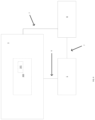
- Figure 4 illustrates an inspection system 1 comprising an analyser 5 configured to perform, at least partly, a method according to any aspect of the disclosure.
- the cargo 101 to be inspected is located in a container 100.
- the inspection system 1 of Figure 4 may be configured to generate the inspection data according to any aspects of the disclosure.
- the analyser 5 is configured to receive the inspection data from the system 1, for example over a communication network 6 which may be wired and/or may be wireless.
- the analyser 5 conventionally comprises at least a processor and a memory in order to carry out an example method according to the disclosure.
- the inspection system 1 is configured to inspect the container 100.
- the inspection may be performed by transmission of inspection radiation from an inspection radiation source to the detectors through the container 100.
- a communication server 8 may be configured to communicate, via a communication network 7 which may be wired and/or may be wireless, with the system 1 and/or the analyser 5.
- the communication server 8 may be configured to provide a remote data management system.
- the server 8 may comprise a database. The database may be configured to store the inspection data and/or the further data of any aspects of the disclosure.
- analyser 5 may be configured to store the inspection data and/or the further data of any aspects of the disclosure.
- the inspection radiation source may comprise sources of other radiation, such as, as non-limiting examples, sources of ionizing radiation, for example gamma rays or neutrons.
- the inspection radiation source may also comprise sources which are not adapted to be activated by a power supply, such as radioactive sources, such as using Co60 or Cs137.
- a computer program, computer program product, or computer readable medium comprising computer program instructions to cause a programmable computer to carry out any one or more of the methods described herein.
- at least some portions of the activities related to the analyser 5 herein may be implemented in software. It is appreciated that software components of the present disclosure may, if desired, be implemented in ROM (read only memory) form. The software components may, generally, be implemented in hardware, if desired, using conventional techniques.
- the server 8 and/or the analyser 5 should not be understood as a single entity, but rather refers to a physical and/or virtual device comprising at least a processor and a memory, the memory may be comprised in one or more servers which can be located in a single location or can be remote from each other to form a distributed network (such as "server farms", e.g., using wired or wireless technology).
- server farms e.g., using wired or wireless technology
- one or more memory elements can store data used for the operations described herein. This includes the memory element being able to store software, logic, code, or processor instructions that are executed to carry out the activities described in the disclosure.
- a processor can execute any type of instructions associated with the data to achieve the operations detailed herein in the disclosure.
- the processor could transform an element or an article (e.g., data) from one state or thing to another state or thing.
- the activities outlined herein may be implemented with fixed logic or programmable logic (e.g., software/computer instructions executed by a processor) and the elements identified herein could be some type of a programmable processor, programmable digital logic (e.g., a field programmable gate array (FPGA), an erasable programmable read only memory (EPROM), an electrically erasable programmable read only memory (EEPROM)), an ASIC that includes digital logic, software, code, electronic instructions, flash memory, optical disks, CD-ROMs, DVD ROMs, magnetic or optical cards, other types of machine-readable mediums suitable for storing electronic instructions, or any suitable combination thereof.
- FPGA field programmable gate array
- EPROM erasable programmable read only memory
- EEPROM electrically eras
- the communications network 6 and the communications network 7 may form only one network.
- the data received by the analyser 5 may be typically received over a range of possible communications networks 6 and/or 7 at least such as: a satellite based communications network; a cable based communications network; a telephony based communications network; a mobile-telephony based communications network; an Internet Protocol (IP) communications network; and/or a computer based communications network.
- IP Internet Protocol
- the communications networks 6 and/or 7 and/or the analyser 5 may comprise one or more networks.
- Networks may be provisioned in any form including, but not limited to, local area networks (LANs), wireless local area networks (WLANs), virtual local area networks (VLANs), metropolitan area networks (MANs), wide area networks (WANs), virtual private networks (VPNs), Intranet, Extranet, any other appropriate architecture or system, or any combination thereof that facilitates communications in a network.
- LANs local area networks
- WLANs wireless local area networks
- VLANs virtual local area networks
- MANs metropolitan area networks
- WANs wide area networks
- VPNs virtual private networks
- Intranet Extranet
- Extranet any other appropriate architecture or system, or any combination thereof that facilitates communications in a network.
- the container 100 may be any type of container, such as a holder, a vessel, or a box, etc.
- the container 100 may thus be, as non-limiting examples, a trailer and/or a palette (for example a palette of European standard, of US standard or of any other standard) and/or a train wagon and/or a tank and/or a boot of a vehicle such as a truck, a van and/or a car and/or a train, and/or the container 100 may be a "shipping container” (such as a tank or an ISO container or a non-ISO container or a Unit Load Device (ULD) container).
- the radiation source is configured to cause inspection of the cargo 101 through the material (usually steel) of walls of the container 100, e.g. for detection and/or identification of the cargo 101.
- the system 1 is configured to, in the inspection mode, cause inspection of the container 100, in totality (i.e. the whole container 100 is inspected) or partially (i.e. only a chosen part of the container is inspected, e.g., typically, when inspecting a vehicle, a cabin of the vehicle may not be inspected, whereas a rear part of the vehicle is inspected).
- the inspection system 1 may be mobile and may be transported from a location to another location (the system 1 may comprise an automotive vehicle). Alternatively or additionally, the inspection system 1 may be static with respect to the ground and cannot be displaced.
- the inspection radiation source may comprise an X-ray generator.
- the energy of the X-rays may be comprised between 100keV and 15MeV, and the dose may be comprised between 2mGy and 20Gy (Gray).
- the power of the X-ray source may be e.g., between 100keV and 9.0MeV, typically e.g., 2MeV, 3.5MeV, 4MeV, or 6MeV, for a steel penetration capacity e.g., between 40mm to 400mm, typically e.g., 300mm (12in).
- the dose may be e.g., between 20mGy and 120mGy.
- the power of the X-ray source may be e.g., between 4MeV and 10MeV, typically e.g., 9MeV, for a steel penetration capacity e.g., between 300mm to 450mm, typically e.g., 410mm (16.1in).
- the dose may be 17Gy.
- the detectors may comprise, amongst other conventional electrical elements, radiation detection lines, such as X-ray detection lines.
- the detectors may further comprise other types of detectors, such as optional gamma and/or neutrons detectors, e.g., adapted to detect the presence of radioactive gamma and/or neutrons emitting materials within the container 100, e.g., simultaneously to the X-ray inspection.
- the detectors may also comprise an electro-hydraulic boom which can operate in a retracted position in a transport mode and in an inspection position. The boom may be operated by hydraulic activators (such as hydraulic cylinders).
- the detectors may also comprise a structure and/or gantry.
- the detection lines may be mounted on the boom or structure and/or gantry, facing the source on the other side of the container 100.
- the system 1 may comprise a motion generation device so that the system 1 may be displaced, the container 100 being static (this mode is sometimes referred to as a 'scanning' mode).
- the motion generation device may cause the container 100 to be displaced, the system 1 being static with respect to the ground.
- the throughput i.e. the number of containers 100 and/or images 10 by unit of time, may be of 20 to 30 images/hour.
- the system 1 in a 'pass-through' mode the system 1 does not comprise a motion generation device and the container moves with respect to the system 1, the system 1 being static with respect to the ground.
- the throughput in the pass-through mode may be higher than the throughput in the scanning mode, and may be for example of 50 to 200 images/hour, or even of 50 to a few thousands images/hour in the case of an inspection of a passing train (for example a throughput of more than 1000 images/hour).
Landscapes
- Engineering & Computer Science (AREA)
- Physics & Mathematics (AREA)
- General Physics & Mathematics (AREA)
- Theoretical Computer Science (AREA)
- Multimedia (AREA)
- Quality & Reliability (AREA)
- Computer Vision & Pattern Recognition (AREA)
- High Energy & Nuclear Physics (AREA)
- Life Sciences & Earth Sciences (AREA)
- General Life Sciences & Earth Sciences (AREA)
- Geophysics (AREA)
- Signal Processing (AREA)
- Analysing Materials By The Use Of Radiation (AREA)
- Health & Medical Sciences (AREA)
- General Health & Medical Sciences (AREA)
- Nuclear Medicine, Radiotherapy & Molecular Imaging (AREA)
- Radiology & Medical Imaging (AREA)
- Spectroscopy & Molecular Physics (AREA)
Claims (14)
- Computerimplementiertes Verfahren (100) zur Verarbeitung von Inspektionsdaten, die mit Fracht assoziiert sind, die mit einer Vielzahl N von Pulsen von Inspektionsstrahlung bestrahlt wird, wobei das Verfahren umfasst:Beziehen (S1) der Inspektionsdaten,wobei die Inspektionsdaten Intensitätswerte von Pixeln eines Inspektionsbilds der Fracht darstellen, die infolgedessen erzeugt werden, dass eine Vielzahl von Detektoren die Vielzahl N von durch die Fracht übertragenen Pulsen erfasst, unddie Inspektionsdaten Daten, die mit einem höheren Energiemodus assoziiert sind, und Daten, die mit einem niedrigeren Energiemodus assoziiert sind, umfassen;Erzeugen (S3) eines Histogramms (200) mit Bins, die Pixelintensitätswerten HM entsprechen, die mit dem höheren Energiemodus assoziiert sind, als eine erste Achse und Bins, die Pixelintensitätswerten LM entsprechen, die mit dem niedrigeren Energiemodus assoziiert sind, als eine zweite Achse,
wobei das Erzeugen des Histogramms ein Binnen eines Vorkommens in den bezogenen Inspektionsdaten für jedes Pixel (i, j) des Inspektionsbilds, das jedem Puls i und jedem Detektor j der Vielzahl von Detektoren entspricht, so dass: Auswählen (S4) einer Bin, die einer häufigsten Bin der Pixelintensitätswerte HM entspricht, auf dem erzeugten Histogramm für jede Bin der Pixelintensitätswerte LM; undErzeugen (S5) einer Umwandlungstabelle (300) durch Abbilden jeder Bin der Pixelintensitätswerte LM mit der ausgewählten Bin der Pixelintensitätswerte HM.
 - Verfahren (100) nach dem vorhergehenden Anspruch, ferner umfassend:Bestimmen (S6) für jedes Pixel des Inspektionsbilds, das mit dem niedrigeren Energiemodus assoziiert ist, ob der Intensitätswert größer als eine vorbestimmte Schwelle ist; undfür jedes Pixel mit einem Intensitätswert, der größer als die vorbestimmte Schwelle ist, Bestimmen (S7) eines umgewandelten Pixelintensitätswerts LM', der einem Pixelintensitätswert HM entspricht, unter Verwendung der erzeugten Umwandlungstabelle, optional ferner umfassend:
für jedes Pixel mit einem Intensitätswert, der kleiner als die vorbestimmte Schwelle ist, Bestimmen (S8) eines durchschnittlichen Pixelintensitätswerts HM', der einem Pixelintensitätswert HM entspricht, so dass:
- Verfahren (100) nach dem vorhergehenden Anspruch, wobei das Bestimmen des umgewandelten Pixelintensitätswerts LM' umfasst:
Interpolieren von abgebildeten Bins in der erzeugen Umwandlungstabelle. - Verfahren (100) nach einem der vorhergehenden Ansprüche, wobei das Beziehen (S1) der Inspektionsdaten ferner umfasst:
Auswählen (S2) mindestens einer Zone, die mit einem Teil des Bilds assoziiert ist, in den Inspektionsdaten, optional wobei der Teil des Bilds mit mindestens einem von: einem oberen Teil des Bilds, einem mittleren Teil des Bilds, einem unteren Teil des Bilds assoziiert ist. - Verfahren (100) nach dem vorhergehenden Anspruch, wobei der Teil des Bilds mit einem Teil der Fracht mit einer konstanten Dicke für die Vielzahl N von Pulsen assoziiert ist.
- Verfahren (100) nach einem der zwei vorhergehenden Ansprüche, wobei das Beziehen (S1) der Inspektionsdaten ferner umfasst:
Auswählen mindestens einer Zone, die mit einem Teil der Fracht mit einem konstanten Material für die Vielzahl N von Pulsen assoziiert ist, in den Inspektionsdaten. - Verfahren (100) nach einem der vorhergehenden Ansprüche, ferner umfassend:
Auswählen einer Bin-Größe für einen Bereich von Intensitäten auf der Basis einer Anzahl von Pixeln des Inspektionsbilds innerhalb des Bereichs von Intensitäten. - Verfahren (100) nach einem der vorhergehenden Ansprüche, wobei das Beziehen der Inspektionsdaten ferner ein Beziehen weiterer Daten umfasst, wobei die weiteren Daten mindestens eines von:Inspektionsdaten, die Intensitätswerte von Pixeln eines weiteren Inspektionsbilds von Extrafracht darstellen, die infolgedessen eines Abtastens der Extrafracht durch Übertragen einer Vielzahl von Pulsen durch die Extrafracht erzeugt werden, und/oderKalibrierdaten, die Intensitätswerte von Pixeln eines Kalibrierbilds darstellen, die infolgedessen eines Abtastens einer Kalibriervorrichtung durch Übertragen einer Vielzahl N von Pulsen durch die Kalibriervorrichtung erzeugt werden, umfassen.
- Verfahren (100) nach einem der vorhergehenden Ansprüche, wobeidie Daten, die mit dem höheren Energiemodus assoziiert sind, Daten umfassen, die unter Verwendung eines Pulses eines höheren Energiemodus erzeugt werden, unddie Daten, die mit dem niedrigen Energiemodus assoziiert sind, Daten umfassen, die unter Verwendung eines Pulses eines niedrigeren Energiemodus erzeugt werden, optional wobei die Vielzahl N von Pulsen Dupletts von Inspektionsstrahlung umfasst, wobei jedes Duplett von Inspektionsstrahlung einen Puls bei höherem Energiemodus und einen Puls bei niedrigerem Energiemodus umfasst.
- Verfahren (100) nach einem der Ansprüche 1 bis 9, wobeidie Daten, die mit dem höheren Energiemodus assoziiert sind, Daten umfassen, die unter Verwendung eines Detektors, der einen höheren Energiemodus umfasst, erzeugt werden, unddie Daten, die mit dem niedrigeren Energiemodus assoziiert sind, Daten umfassen, die unter Verwendung eines Detektors, der einen niedrigeren Energiemodus umfasst, erzeugt werden.
- Verfahren (100) nach einem der vorhergehenden Ansprüche bei Abhängigkeit von Anspruch 2, ferner umfassend ein Erzeugen (S9) eines verbesserten Inspektionsbilds unter Verwendung:der Pixelintensitätswerte HM, die mit dem höheren Energiemodus assoziiert sind; undmindestens eines der bestimmten umgewandelten Pixelintensitätswerte LM' und/oder der bestimmten durchschnittlichen Pixelintensitätswerte HM'.
- Verfahren (100) nach dem vorhergehenden Anspruch bei Abhängigkeit von Anspruch 2, wobei das Erzeugen (S9) des verbesserten Inspektionsbilds für jeden Pixelintensitätswert S, der mit dem niedrigeren Energiemodus LM assoziiert ist, in dem bezogenen Inspektionsbild ein Verwenden eines Intensitätswerts V in dem verbesserten Inspektionsbild umfasst, so dass:
 wobei T der vorbestimmte Schwellenwert ist,LM' der umgewandelte Pixelintensitätswert ist, der aus der Umwandlungstabelle berechnet wird und S entspricht,HM' der durchschnittliche Pixelintensitätswert ist, der S entspricht, undW eine vorbestimmte Breite einer Übergangszone zwischen einer vorbestimmten Verwendung von LM' und einer vorbestimmten Verwendung von HM' ist.
 - Analysator (5), umfassend:einen Prozessor; undeinen Speicher, der Anweisungen speichert, die bei Ausführung durch den Prozessor den Prozessor dazu befähigen, ein Verfahren (100) zur Verarbeitung von Inspektionsdaten, die mit Fracht assoziiert sind, die mit einer Vielzahl N von Pulsen von Inspektionsstrahlung bestrahlt wird, auszuführen, wobei das Verfahren umfasst:Beziehen der Inspektionsdaten,wobei die Inspektionsdaten Intensitätswerte von Pixeln eines Inspektionsbilds der Fracht darstellen, die infolgedessen erzeugt werden, dass eine Vielzahl von Detektoren die Vielzahl N von durch die Fracht übertragenen Pulsen erfasst, unddie Inspektionsdaten Daten, die mit einem höheren Energiemodus assoziiert sind, und Daten, die mit einem niedrigeren Energiemodus assoziiert sind, umfassen;Erzeugen eines Histogramms mit Bins, die Pixelintensitätswerten HM entsprechen, die mit dem höheren Energiemodus assoziiert sind, als eine erste Achse und Bins, die Pixelintensitätswerten LM entsprechen, die mit dem niedrigeren Energiemodus assoziiert sind, als eine zweite Achse,
wobei das Erzeugen des Histogramms ein Binnen eines Vorkommens in den bezogenen Inspektionsdaten für jedes Pixel (i, j) des Inspektionsbilds, das jedem Puls i und jedem Detektor j der Vielzahl von Detektoren entspricht, so dass: Auswählen einer Bin, die einer häufigsten Bin der Pixelintensitätswerte HM entspricht, auf dem erzeugten Histogramm für jede Bin der Pixelintensitätswerte LM; undErzeugen einer Umwandlungstabelle durch Abbilden jeder Bin der Pixelintensitätswerte LM mit der ausgewählten Bin der Pixelintensitätswerte HM, optional wobei der Prozessor dazu konfiguriert ist, das Verfahren nach einem der Ansprüche 2 bis 12 durchzuführen.
 - Computerprogramm oder Computerprogrammprodukt, das Anweisungen umfasst, die bei Ausführung durch einen Prozessor den Prozessor dazu befähigen, das Verfahren (100) nach einem der Ansprüche 1 bis 12 auszuführen.
Applications Claiming Priority (2)
| Application Number | Priority Date | Filing Date | Title |
|---|---|---|---|
| GB2003046.6A GB2592607B (en) | 2020-03-03 | 2020-03-03 | Resolution improvement in dual energy |
| PCT/GB2021/050521 WO2021176207A1 (en) | 2020-03-03 | 2021-03-02 | Resolution improvement in dual energy |
Publications (2)
| Publication Number | Publication Date |
|---|---|
| EP4115384A1 EP4115384A1 (de) | 2023-01-11 |
| EP4115384B1 true EP4115384B1 (de) | 2025-06-11 |
Family
ID=70278653
Family Applications (1)
| Application Number | Title | Priority Date | Filing Date |
|---|---|---|---|
| EP21710041.1A Active EP4115384B1 (de) | 2020-03-03 | 2021-03-02 | Auflösungsverbesserung bei dualer energie |
Country Status (5)
| Country | Link |
|---|---|
| US (1) | US12276770B2 (de) |
| EP (1) | EP4115384B1 (de) |
| CN (1) | CN115298689A (de) |
| GB (1) | GB2592607B (de) |
| WO (1) | WO2021176207A1 (de) |
Families Citing this family (1)
| Publication number | Priority date | Publication date | Assignee | Title |
|---|---|---|---|---|
| GB2594449B (en) | 2020-04-20 | 2023-07-19 | Smiths Detection France S A S | Pulse frequency adjustment |
Family Cites Families (10)
| Publication number | Priority date | Publication date | Assignee | Title |
|---|---|---|---|---|
| JP5173405B2 (ja) | 2004-03-01 | 2013-04-03 | バリアン・メディカル・システムズ・インコーポレイテッド | 2エネルギー放射線走査および遅発中性子検出による物体調査 |
| US20080167552A1 (en) * | 2007-01-04 | 2008-07-10 | General Electric Company | System and method of generating an image of a contrast agent injected into an imaged subject |
| US7983382B2 (en) * | 2008-11-26 | 2011-07-19 | General Electric Company | System and method for material segmentation utilizing computed tomography scans |
| DE102011006398A1 (de) * | 2011-03-30 | 2012-10-04 | Siemens Aktiengesellschaft | Verfahren, Bildverarbeitungseinrichtung und Computertomographiesystem zur Ermittlung eines Anteils von nekrotischem Gewebe sowie Computerprogrammprodukt mit Programmcodeabschnitten zur Ermittlung eines Anteils von nekrotischem Gewebe |
| US9128584B2 (en) * | 2013-02-15 | 2015-09-08 | Carl Zeiss X-ray Microscopy, Inc. | Multi energy X-ray microscope data acquisition and image reconstruction system and method |
| KR101635980B1 (ko) * | 2013-12-30 | 2016-07-05 | 삼성전자주식회사 | 방사선 디텍터 및 그에 따른 컴퓨터 단층 촬영 장치 |
| US9964499B2 (en) * | 2014-11-04 | 2018-05-08 | Toshiba Medical Systems Corporation | Method of, and apparatus for, material classification in multi-energy image data |
| KR20190003960A (ko) * | 2016-05-03 | 2019-01-10 | 라피스캔 시스템스, 인코포레이티드 | 방사선 신호 처리 시스템 |
| GB2556941B (en) * | 2016-11-28 | 2021-10-20 | Smiths Heimann Sas | Detection of irregularities using registration |
| GB2589926B (en) * | 2019-12-13 | 2024-10-23 | Smiths Detection France S A S | Correction of images and depth information for detection with matrix |
-
2020
- 2020-03-03 GB GB2003046.6A patent/GB2592607B/en active Active
-
2021
- 2021-03-02 WO PCT/GB2021/050521 patent/WO2021176207A1/en not_active Ceased
- 2021-03-02 CN CN202180018359.XA patent/CN115298689A/zh active Pending
- 2021-03-02 US US17/908,424 patent/US12276770B2/en active Active
- 2021-03-02 EP EP21710041.1A patent/EP4115384B1/de active Active
Also Published As
| Publication number | Publication date |
|---|---|
| WO2021176207A1 (en) | 2021-09-10 |
| GB2592607A (en) | 2021-09-08 |
| US12276770B2 (en) | 2025-04-15 |
| CN115298689A (zh) | 2022-11-04 |
| GB2592607B (en) | 2024-06-19 |
| EP4115384A1 (de) | 2023-01-11 |
| US20230089927A1 (en) | 2023-03-23 |
| GB202003046D0 (en) | 2020-04-15 |
Similar Documents
| Publication | Publication Date | Title |
|---|---|---|
| US10713759B2 (en) | Denoising and/or zooming of inspection images | |
| EP3912084B1 (de) | Klassifizierer mit datenerzeugung | |
| EP3491425B1 (de) | Rasterartige überprüfungsvorrichtung und verfahren | |
| EP3545493B1 (de) | Erfassung von unregelmässigkeiten mittels registrierung | |
| US8090150B2 (en) | Method and system for identifying a containment vessel | |
| EP4115384B1 (de) | Auflösungsverbesserung bei dualer energie | |
| US12385854B2 (en) | Methods and systems for performing on-the-fly automatic calibration adjustments of X-ray inspection systems | |
| US12203879B2 (en) | Pulse frequency adjustment | |
| EP4409511A1 (de) | Entrauschen und superauflösung | |
| CN107077728B (zh) | 确定图像中的均匀度 | |
| WO2026017671A1 (en) | Depth information in inspection images | |
| GB2636094A (en) | Decomposition of inspection image of cargo | |
| US20230334639A1 (en) | Detection of liquid |
Legal Events
| Date | Code | Title | Description |
|---|---|---|---|
| STAA | Information on the status of an ep patent application or granted ep patent |
Free format text: STATUS: UNKNOWN |
|
| STAA | Information on the status of an ep patent application or granted ep patent |
Free format text: STATUS: THE INTERNATIONAL PUBLICATION HAS BEEN MADE |
|
| PUAI | Public reference made under article 153(3) epc to a published international application that has entered the european phase |
Free format text: ORIGINAL CODE: 0009012 |
|
| STAA | Information on the status of an ep patent application or granted ep patent |
Free format text: STATUS: REQUEST FOR EXAMINATION WAS MADE |
|
| 17P | Request for examination filed |
Effective date: 20220930 |
|
| AK | Designated contracting states |
Kind code of ref document: A1 Designated state(s): AL AT BE BG CH CY CZ DE DK EE ES FI FR GB GR HR HU IE IS IT LI LT LU LV MC MK MT NL NO PL PT RO RS SE SI SK SM TR |
|
| DAV | Request for validation of the european patent (deleted) | ||
| DAX | Request for extension of the european patent (deleted) | ||
| REG | Reference to a national code |
Ref country code: DE Ref legal event code: R079 Free format text: PREVIOUS MAIN CLASS: G06T0005000000 Ipc: G06T0005920000 Ref country code: DE Ref legal event code: R079 Ref document number: 602021032092 Country of ref document: DE Free format text: PREVIOUS MAIN CLASS: G06T0005000000 Ipc: G06T0005920000 |
|
| RIC1 | Information provided on ipc code assigned before grant |
Ipc: G06T 5/40 20060101ALI20241120BHEP Ipc: G06T 7/00 20170101ALI20241120BHEP Ipc: G06T 5/92 20240101AFI20241120BHEP |
|
| GRAP | Despatch of communication of intention to grant a patent |
Free format text: ORIGINAL CODE: EPIDOSNIGR1 |
|
| STAA | Information on the status of an ep patent application or granted ep patent |
Free format text: STATUS: GRANT OF PATENT IS INTENDED |
|
| INTG | Intention to grant announced |
Effective date: 20250108 |
|
| GRAS | Grant fee paid |
Free format text: ORIGINAL CODE: EPIDOSNIGR3 |
|
| GRAA | (expected) grant |
Free format text: ORIGINAL CODE: 0009210 |
|
| STAA | Information on the status of an ep patent application or granted ep patent |
Free format text: STATUS: THE PATENT HAS BEEN GRANTED |
|
| AK | Designated contracting states |
Kind code of ref document: B1 Designated state(s): AL AT BE BG CH CY CZ DE DK EE ES FI FR GB GR HR HU IE IS IT LI LT LU LV MC MK MT NL NO PL PT RO RS SE SI SK SM TR |
|
| REG | Reference to a national code |
Ref country code: GB Ref legal event code: FG4D |
|
| REG | Reference to a national code |
Ref country code: CH Ref legal event code: EP |
|
| REG | Reference to a national code |
Ref country code: IE Ref legal event code: FG4D |
|
| REG | Reference to a national code |
Ref country code: DE Ref legal event code: R096 Ref document number: 602021032092 Country of ref document: DE |
|
| PG25 | Lapsed in a contracting state [announced via postgrant information from national office to epo] |
Ref country code: FI Free format text: LAPSE BECAUSE OF FAILURE TO SUBMIT A TRANSLATION OF THE DESCRIPTION OR TO PAY THE FEE WITHIN THE PRESCRIBED TIME-LIMIT Effective date: 20250611 Ref country code: ES Free format text: LAPSE BECAUSE OF FAILURE TO SUBMIT A TRANSLATION OF THE DESCRIPTION OR TO PAY THE FEE WITHIN THE PRESCRIBED TIME-LIMIT Effective date: 20250611 |
|
| REG | Reference to a national code |
Ref country code: LT Ref legal event code: MG9D |
|
| PG25 | Lapsed in a contracting state [announced via postgrant information from national office to epo] |
Ref country code: GR Free format text: LAPSE BECAUSE OF FAILURE TO SUBMIT A TRANSLATION OF THE DESCRIPTION OR TO PAY THE FEE WITHIN THE PRESCRIBED TIME-LIMIT Effective date: 20250912 Ref country code: NO Free format text: LAPSE BECAUSE OF FAILURE TO SUBMIT A TRANSLATION OF THE DESCRIPTION OR TO PAY THE FEE WITHIN THE PRESCRIBED TIME-LIMIT Effective date: 20250911 |
|
| REG | Reference to a national code |
Ref country code: NL Ref legal event code: MP Effective date: 20250611 |
|
| PG25 | Lapsed in a contracting state [announced via postgrant information from national office to epo] |
Ref country code: BG Free format text: LAPSE BECAUSE OF FAILURE TO SUBMIT A TRANSLATION OF THE DESCRIPTION OR TO PAY THE FEE WITHIN THE PRESCRIBED TIME-LIMIT Effective date: 20250611 |
|
| PG25 | Lapsed in a contracting state [announced via postgrant information from national office to epo] |
Ref country code: HR Free format text: LAPSE BECAUSE OF FAILURE TO SUBMIT A TRANSLATION OF THE DESCRIPTION OR TO PAY THE FEE WITHIN THE PRESCRIBED TIME-LIMIT Effective date: 20250611 |
|
| PG25 | Lapsed in a contracting state [announced via postgrant information from national office to epo] |
Ref country code: RS Free format text: LAPSE BECAUSE OF FAILURE TO SUBMIT A TRANSLATION OF THE DESCRIPTION OR TO PAY THE FEE WITHIN THE PRESCRIBED TIME-LIMIT Effective date: 20250911 |
|
| P01 | Opt-out of the competence of the unified patent court (upc) registered |
Free format text: CASE NUMBER: UPC_APP_7476_4115384/2025 Effective date: 20250918 |
|
| PG25 | Lapsed in a contracting state [announced via postgrant information from national office to epo] |
Ref country code: LV Free format text: LAPSE BECAUSE OF FAILURE TO SUBMIT A TRANSLATION OF THE DESCRIPTION OR TO PAY THE FEE WITHIN THE PRESCRIBED TIME-LIMIT Effective date: 20250611 |
|
| PG25 | Lapsed in a contracting state [announced via postgrant information from national office to epo] |
Ref country code: NL Free format text: LAPSE BECAUSE OF FAILURE TO SUBMIT A TRANSLATION OF THE DESCRIPTION OR TO PAY THE FEE WITHIN THE PRESCRIBED TIME-LIMIT Effective date: 20250611 |
|
| PG25 | Lapsed in a contracting state [announced via postgrant information from national office to epo] |
Ref country code: PT Free format text: LAPSE BECAUSE OF FAILURE TO SUBMIT A TRANSLATION OF THE DESCRIPTION OR TO PAY THE FEE WITHIN THE PRESCRIBED TIME-LIMIT Effective date: 20251013 |
|
| REG | Reference to a national code |
Ref country code: AT Ref legal event code: MK05 Ref document number: 1802879 Country of ref document: AT Kind code of ref document: T Effective date: 20250611 |
|
| PG25 | Lapsed in a contracting state [announced via postgrant information from national office to epo] |
Ref country code: IS Free format text: LAPSE BECAUSE OF FAILURE TO SUBMIT A TRANSLATION OF THE DESCRIPTION OR TO PAY THE FEE WITHIN THE PRESCRIBED TIME-LIMIT Effective date: 20251011 |
|
| PG25 | Lapsed in a contracting state [announced via postgrant information from national office to epo] |
Ref country code: AT Free format text: LAPSE BECAUSE OF FAILURE TO SUBMIT A TRANSLATION OF THE DESCRIPTION OR TO PAY THE FEE WITHIN THE PRESCRIBED TIME-LIMIT Effective date: 20250611 Ref country code: SM Free format text: LAPSE BECAUSE OF FAILURE TO SUBMIT A TRANSLATION OF THE DESCRIPTION OR TO PAY THE FEE WITHIN THE PRESCRIBED TIME-LIMIT Effective date: 20250611 |
|
| PGFP | Annual fee paid to national office [announced via postgrant information from national office to epo] |
Ref country code: FR Payment date: 20251231 Year of fee payment: 6 |
|
| PG25 | Lapsed in a contracting state [announced via postgrant information from national office to epo] |
Ref country code: CZ Free format text: LAPSE BECAUSE OF FAILURE TO SUBMIT A TRANSLATION OF THE DESCRIPTION OR TO PAY THE FEE WITHIN THE PRESCRIBED TIME-LIMIT Effective date: 20250611 |
|
| PG25 | Lapsed in a contracting state [announced via postgrant information from national office to epo] |
Ref country code: PL Free format text: LAPSE BECAUSE OF FAILURE TO SUBMIT A TRANSLATION OF THE DESCRIPTION OR TO PAY THE FEE WITHIN THE PRESCRIBED TIME-LIMIT Effective date: 20250611 |
|
| PG25 | Lapsed in a contracting state [announced via postgrant information from national office to epo] |
Ref country code: EE Free format text: LAPSE BECAUSE OF FAILURE TO SUBMIT A TRANSLATION OF THE DESCRIPTION OR TO PAY THE FEE WITHIN THE PRESCRIBED TIME-LIMIT Effective date: 20250611 |
|
| PG25 | Lapsed in a contracting state [announced via postgrant information from national office to epo] |
Ref country code: SK Free format text: LAPSE BECAUSE OF FAILURE TO SUBMIT A TRANSLATION OF THE DESCRIPTION OR TO PAY THE FEE WITHIN THE PRESCRIBED TIME-LIMIT Effective date: 20250611 |
|
| REG | Reference to a national code |
Ref country code: DE Ref legal event code: R097 Ref document number: 602021032092 Country of ref document: DE |
|
| PGFP | Annual fee paid to national office [announced via postgrant information from national office to epo] |
Ref country code: GB Payment date: 20260106 Year of fee payment: 6 |
|
| PG25 | Lapsed in a contracting state [announced via postgrant information from national office to epo] |
Ref country code: DK Free format text: LAPSE BECAUSE OF FAILURE TO SUBMIT A TRANSLATION OF THE DESCRIPTION OR TO PAY THE FEE WITHIN THE PRESCRIBED TIME-LIMIT Effective date: 20250611 |
|
| PGFP | Annual fee paid to national office [announced via postgrant information from national office to epo] |
Ref country code: DE Payment date: 20260102 Year of fee payment: 6 |
|
| PG25 | Lapsed in a contracting state [announced via postgrant information from national office to epo] |
Ref country code: IT Free format text: LAPSE BECAUSE OF FAILURE TO SUBMIT A TRANSLATION OF THE DESCRIPTION OR TO PAY THE FEE WITHIN THE PRESCRIBED TIME-LIMIT Effective date: 20250611 |
|
| PLBE | No opposition filed within time limit |
Free format text: ORIGINAL CODE: 0009261 |
|
| STAA | Information on the status of an ep patent application or granted ep patent |
Free format text: STATUS: NO OPPOSITION FILED WITHIN TIME LIMIT |
|
| REG | Reference to a national code |
Ref country code: CH Ref legal event code: L10 Free format text: ST27 STATUS EVENT CODE: U-0-0-L10-L00 (AS PROVIDED BY THE NATIONAL OFFICE) Effective date: 20260423 |