EP4114144A1 - Induction heating device - Google Patents
Induction heating device Download PDFInfo
- Publication number
- EP4114144A1 EP4114144A1 EP20922202.5A EP20922202A EP4114144A1 EP 4114144 A1 EP4114144 A1 EP 4114144A1 EP 20922202 A EP20922202 A EP 20922202A EP 4114144 A1 EP4114144 A1 EP 4114144A1
- Authority
- EP
- European Patent Office
- Prior art keywords
- coil
- sensing
- layer sensing
- layer
- coils
- Prior art date
- Legal status (The legal status is an assumption and is not a legal conclusion. Google has not performed a legal analysis and makes no representation as to the accuracy of the status listed.)
- Granted
Links
Images






Classifications
-
- H—ELECTRICITY
- H05—ELECTRIC TECHNIQUES NOT OTHERWISE PROVIDED FOR
- H05B—ELECTRIC HEATING; ELECTRIC LIGHT SOURCES NOT OTHERWISE PROVIDED FOR; CIRCUIT ARRANGEMENTS FOR ELECTRIC LIGHT SOURCES, IN GENERAL
- H05B6/00—Heating by electric, magnetic or electromagnetic fields
- H05B6/02—Induction heating
- H05B6/10—Induction heating apparatus, other than furnaces, for specific applications
- H05B6/12—Cooking devices
- H05B6/1209—Cooking devices induction cooking plates or the like and devices to be used in combination with them
- H05B6/1245—Cooking devices induction cooking plates or the like and devices to be used in combination with them with special coil arrangements
- H05B6/1272—Cooking devices induction cooking plates or the like and devices to be used in combination with them with special coil arrangements with more than one coil or coil segment per heating zone
-
- H—ELECTRICITY
- H05—ELECTRIC TECHNIQUES NOT OTHERWISE PROVIDED FOR
- H05B—ELECTRIC HEATING; ELECTRIC LIGHT SOURCES NOT OTHERWISE PROVIDED FOR; CIRCUIT ARRANGEMENTS FOR ELECTRIC LIGHT SOURCES, IN GENERAL
- H05B6/00—Heating by electric, magnetic or electromagnetic fields
- H05B6/02—Induction heating
- H05B6/10—Induction heating apparatus, other than furnaces, for specific applications
- H05B6/12—Cooking devices
- H05B6/1209—Cooking devices induction cooking plates or the like and devices to be used in combination with them
- H05B6/1245—Cooking devices induction cooking plates or the like and devices to be used in combination with them with special coil arrangements
- H05B6/1263—Cooking devices induction cooking plates or the like and devices to be used in combination with them with special coil arrangements using coil cooling arrangements
-
- H—ELECTRICITY
- H05—ELECTRIC TECHNIQUES NOT OTHERWISE PROVIDED FOR
- H05B—ELECTRIC HEATING; ELECTRIC LIGHT SOURCES NOT OTHERWISE PROVIDED FOR; CIRCUIT ARRANGEMENTS FOR ELECTRIC LIGHT SOURCES, IN GENERAL
- H05B6/00—Heating by electric, magnetic or electromagnetic fields
- H05B6/02—Induction heating
- H05B6/06—Control, e.g. of temperature, of power
- H05B6/062—Control, e.g. of temperature, of power for cooking plates or the like
-
- H—ELECTRICITY
- H05—ELECTRIC TECHNIQUES NOT OTHERWISE PROVIDED FOR
- H05B—ELECTRIC HEATING; ELECTRIC LIGHT SOURCES NOT OTHERWISE PROVIDED FOR; CIRCUIT ARRANGEMENTS FOR ELECTRIC LIGHT SOURCES, IN GENERAL
- H05B6/00—Heating by electric, magnetic or electromagnetic fields
- H05B6/02—Induction heating
- H05B6/06—Control, e.g. of temperature, of power
- H05B6/062—Control, e.g. of temperature, of power for cooking plates or the like
- H05B6/065—Control, e.g. of temperature, of power for cooking plates or the like using coordinated control of multiple induction coils
-
- H—ELECTRICITY
- H05—ELECTRIC TECHNIQUES NOT OTHERWISE PROVIDED FOR
- H05B—ELECTRIC HEATING; ELECTRIC LIGHT SOURCES NOT OTHERWISE PROVIDED FOR; CIRCUIT ARRANGEMENTS FOR ELECTRIC LIGHT SOURCES, IN GENERAL
- H05B6/00—Heating by electric, magnetic or electromagnetic fields
- H05B6/02—Induction heating
- H05B6/36—Coil arrangements
- H05B6/44—Coil arrangements having more than one coil or coil segment
-
- H—ELECTRICITY
- H05—ELECTRIC TECHNIQUES NOT OTHERWISE PROVIDED FOR
- H05B—ELECTRIC HEATING; ELECTRIC LIGHT SOURCES NOT OTHERWISE PROVIDED FOR; CIRCUIT ARRANGEMENTS FOR ELECTRIC LIGHT SOURCES, IN GENERAL
- H05B2213/00—Aspects relating both to resistive heating and to induction heating, covered by H05B3/00 and H05B6/00
- H05B2213/05—Heating plates with pan detection means
Definitions
- an induction heating device that can detect whether a container placed on a heating coil is eccentric and can sense a direction of eccentricity, by using a plurality of sensing coils having a sector shape and being arranged circumferentially on the heating coil.
- an induction heating device that heats a food item to be cooked by using a magnetic field.
- the induction heating device supplies current to a heating coil therein, a magnetic field is generated in a direction of the container and induces eddy current to the container, to heat the container.
- the heating coil and the container need to be aligned perpendicularly.
- a container is usually placed approximately on the induction heating device.
- the container is partially off-center (hereafter, being eccentric) on the heating coil of the induction heating device, and due to eccentricity, a food item to be cooked in the container is undercooked or overheated depending on a position of the food item, causing deterioration in cooking quality.
- KR Patent No. 10-1904642 hereafter, a prior art document.
- a method of detecting eccentricity according to the prior art document is described with reference to FIGS. 1 and 2 .
- FIGS. 1 and 2 are excerpted from the drawings ( FIGS. 1 and 2 ) of the prior art document, and are view for describing the method of the related art by which eccentricity of a container is sensed.
- an induction heating device 1' includes a heating coil 103, and a plurality of sensing coils 105, 106 being arranged around the heating coil 103 and sensing a load placed in a heating zone 102.
- a current measuring part (not illustrated) measures current flowing in each of the sensing coils 105, 106 and compares the measurement with a reference value, to determine whether a load is mounted onto the heating zone 102.
- the plurality of sensing coils 105, 106 are necessarily placed around the heating coil 103, to sense eccentricity. That is, according to the prior art document, a coil needs to be placed even in a zone where heating is not actually performed, causing inefficiency in the usability of space when it comes to design of the induction heating device 1'.
- One objective of the present disclosure is to provide an induction heating device that can detect whether a container is eccentric by using a sensing coil placed on a heating coil.
- Another objective of the present disclosure is to provide an induction heating device that can sense a direction of eccentricity of a container, by using sensing coils arranged circumferentially side by side.
- Yet another objective of the present disclosure is to provide an induction heating device that prevents a magnetic field output from a heating coil from being offset by a sensing coil placed on the heating coil.
- an induction heating device may include a plurality of sensing coils being arranged circumferentially side by side on a heating coil, and based on a change in resonance current generated in each sensing coil, detect whether a container is eccentric.
- the induction heating device can identify at least one sensing coil where resonance current changes, among the plurality of sensing coils arranged circumferentially side by side, and based on a direction in which the identified sensing coil is arranged, sense a direction of eccentricity of a container.
- the plurality of sensing coils are disposed in two layers, and any one layer of sensing coils and the other layer of sensing coils are designed to be wound in opposite directions, to prevent a magnetic field output from the heating coil from being offset by the sensing coils placed on the heating coil.
- an induction heating device may detect whether a container is eccentric, by using a sensing coil placed on a heating coil, thereby ensuring efficiency in usability of space when it comes to design of a device for sensing eccentricity.
- the induction heating device may sense a direction of eccentricity of a container by using sensing coils arranged circumferentially side by side, thereby informing a user of a direction of movement of the container and effectively guiding the container to the correction position.
- the induction heating device may prevent a magnetic field output from the heating coil from being offset by the sensing coil disposed on the heating coil, thereby preventing deterioration in heating efficiency, caused by the operation of sensing eccentricity.
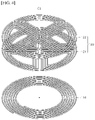
- FIG. 3 is a view showing an induction heating device of one embodiment, and a container placed on the induction heating device. Additionally, FIG. 4 is a view showing that a heating coil separates from a sensing part including first and second layer sensing coils, in one embodiment.
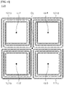
- FIGS. 5 to 7 are views showing disposition of sensing coils in each embodiment.
- FIG. 8 is view showing that a first layer sensing coil and a second layer sensing coil are misaligned
- FIG. 9 is a view showing that a first layer sensing coil and a second layer sensing coil, wound in opposite directions, connect to each other.
- FIG. 10 is a view showing that any one first layer sensing coil is disposed to overlap two adjacent second layer sensing coils.
- FIG. 11 is a view showing that a controller allows resonance current to flow in a pair of a first layer sensing coil and a second layer sensing coil
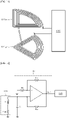
- FIG. 12 is a view showing that a controller is provided with an output of an oscillator connected to a sensing coil.
- FIG. 13 is a view showing that a container is placed in the correction position on a sensing coil
- FIG. 14 is a view showing electrical properties of resonance current flowing in each pair of sensing coils when a container is placed in the correction position.
- FIG. 15 is a view showing that a container is eccentric on a sensing coil.
- FIG. 16 is a view showing that amplitude of resonance current flowing in any one pair of sensing coils decreases when a container is eccentric, and
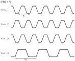
- FIG. 17 is a view showing that a frequency of resonance current flowing in any one pair of sensing coils decreases when a container is eccentric.
- the induction heating device 1 of one embodiment may include an upper plate 10 on which a container 2 is placed, and a control plate 30 on which user manipulation is performed.
- a display 31 displaying operation information, state information and the like of the induction heating device 1, a plurality of buttons 32 for inputting user manipulation, and a knob switch 33 may be disposed on the control plate 30.
- the knob switch 33 may generate a signal based on a degree to which the knob switch 33 rotates, and a heating coil 110 described hereafter may output power based on the signal generated by the knob switch 33. In other words, the output of the heating coil 110 may be controlled based on the degree of the knob switch 33's rotation.
- the heating coil 110 and a sensing part 120 may be disposed inside the upper plate 10, and a guide line 20 for guiding the container 2 to the upper portion of the heating coil 110 may be formed on the upper plate 10.
- a magnetic field may be generated in the heating coil 110.
- the magnetic field generated in the heating coil 110 may induce eddy current to the container 2 placed on the heating coil 110 of the upper plate 10, and the container 2 may be heated by Joule's heat produced by the induced current.
- the container 2 may be made of any ingredient having a magnetic property.
- the container 2 may be made of cast iron including iron (Fe), or a clad where iron (Fe) and stainless steel and the like are joined.
- the induction heating device 1 heats the container 2 using the magnetic field produced in the heating coil 110.
- the heating coil 110 and the container 2 need to be aligned perpendicularly, to maximize heating efficiency and evenly heat the container 2.
- the container 2 may be away from the center of the heating coil 110 of the induction heating device 1.
- the induction heating device 1 itself needs to detect eccentricity of the container 2, so that a user can recognize eccentricity of the container 2.
- the induction heating device 1 may include a sensing part 120 comprised of a plurality of first layer sensing coils 121 and a plurality of second layer sensing coils 122.
- a sensing part 120 comprised of a plurality of first layer sensing coils 121 and a plurality of second layer sensing coils 122.
- structural features of the sensing part 120 are specifically described with reference to FIGS. 4 to 10 .
- the sensing part 120 may include the plurality of first layer sensing coils 121 and the plurality of second layer sensing coils 122 that are spaced from a central perpendicular line CL of the heating coil 110 at regular intervals and arranged side by side along a circumferential direction.
- the plurality of first layer sensing coils 121 and the plurality of second layer sensing coils 122 may be disposed to contact each other perpendicularly, or spaced from each other perpendicularly. However, to offset electromotive force induced by the magnetic field generated in the heating coil 110 as described below, the plurality of first layer sensing coils 121 and the plurality of second layer sensing coils 122 are close to each other perpendicularly, for example.
- the 'first layer sensing coil' described hereafter refers to at least one of the plurality of first layer sensing coils 121 and that the 'second layer sensing coil' described hereafter refers to at least one of the plurality of second layer sensing coils 122.
- the plurality of first layer sensing coils 121 and the plurality of second layer sensing coils 122 are collectively referred to as sensing coils, and when necessary, the plurality of first layer sensing coils 121 is distinguished from the plurality of second layer sensing coils 122.
- the container 2's eccentricity occurs when the bottom surface of the container 2 is away from the center of the heating coil 110.
- the sensing part 120 may be formed around the central perpendicular line CL of the heating coil 110. Additionally, the surface area of the sensing part 120 may be the same as or greater than the surface area of the heating coil 110. For example, when the heating coil 110 and the sensing part 120 have a circular shape, as illustrated in FIG. 4 , the center of the sensing part 120 and the center of the heating coil 110 are placed on the same perpendicular line, and the diameter of the sensing part 120 may be the same as or greater than the diameter of the heating coil 110.
- the plurality of first layer sensing coils 121 may be disposed on the same horizontal surface, and the plurality of second layer sensing coils 122 may also be disposed on the same horizontal surface.
- the plurality of first and second layer sensing coils 121, 122 may have the same shape.
- any two horizontally adjacent sensing coils may be spaced from each other at a regular interval.
- the plurality of first layer sensing coils 121 may be spaced from each other at regular intervals
- the plurality of second layer sensing coils 122 may be spaced from each other at regular intervals.
- first and second layer sensing coils 121, 122 have the same shape as described above, the shape and structure of the first layer sensing coil 121 are only described with reference to FIGS. 5 to 7 .
- each of the plurality of first layer sensing coils 121 may have a circular planar coil shape.
- the first layer sensing coils 121 may be respectively spaced from the central perpendicular line CL of the heating coil 110 at a regular interval, and spaced from each other at regular intervals.
- the plurality of first layer sensing coils 121 may include circular 1-1 to 1-4 sensing coils 121a, 121b, 121c, 121d.
- the centers of the 1-1 to 1-4 sensing coils 121a, 121b, 121c, 121d are respectively defined as 1 to 4 center points cp1, cp2, cp3, cp4
- a distance between the first center point cp1 and the central perpendicular line CL may be the same as a distance between the second center point cp2 and the central perpendicular line CL, a distance between the third center point cp3 and the central perpendicular line CL, and a distance between the fourth center point cp4 and the central perpendicular line CL.
- a distance between the first center point cp1 and the second center point cp2 may be the same as a distance between the second center point cp2 and the third center point cp3, a distance between the third center point cp3 and the fourth center point cp4, and a distance between the fourth center point cp4 and the first center point cp1.
- first and second layer sensing coils 121, 122 may be respectively disposed to contact each other.
- adjacent first layer sensing coils 121 may be disposed to contact each other on the same horizontal surface
- adjacent second layer sensing coils 122 may also be disposed to contact each other on the same horizontal surface.
- each of the plurality of first layer sensing coils 121 may include square 1-1 to 1-4 sensing coils 121a, 121b, 121c, 121d.
- the 1-1 sensing coil 121a may be disposed to contact the adjacent 1-2 and 1-4 sensing coils 121b, 121d respectively
- the 1-3 sensing coil 121c may be disposed to contact the adjacent 1-2 and 1-4 sensing coils 121b, 121d respectively.
- the first layer sensing coils 121 may be respectively spaced from the central perpendicular line CL of the heating coil 110 at a regular interval, and spaced from each other at regular intervals.
- a distance between the first center point cp1 and the central perpendicular line CL may be the same as a distance between the second center point cp2 and the central perpendicular line CL, a distance between the third center point cp3 and the central perpendicular line CL, and a distance between the fourth center point cp4 and the central perpendicular line CL.
- a distance between the first center point cp1 and the second center point cp2 may be the same as a distance between the second center point cp2 and the third center point cp3, a distance between the third center point cp3 and the fourth center point cp4, and a distance between the fourth center point cp4 and the first center point cp1.
- the plurality of first and second layer sensing coils 121, 122 may have a sector shape and be formed around the central perpendicular line CL.
- each of the plurality of first layer sensing coils 121 may include sector-shaped 1-1 to 1-4 sensing coils 121a, 121b, 121c, 121d.
- Each first layer sensing coil 121 may have a sector shape in which one side and the other side are surrounded by an arc, and have a central angle ⁇ and a radius r.
- each of the 1-1 to 1-4 sensing coils 121a, 121b, 121c, 121d may be disposed in a way that the outer edges (the two sides) of each of the 1-1 to 1-4 sensing coils 121a, 121b, 121c, 121d contact adjacent sensing coils.
- the two sides of any one sensing coil, among the 1-1 to 1-4 sensing coils 121a, 121b, 121c, 121d may respectively contact any one side of another sensing coil.
- a total of the central angle of each first layer sensing coil 121 may be 360 degrees.
- the central angle of each of the 1-1 to 1-4 sensing coils 121a, 121b, 121c, 121d may be 90 degrees, and the entire shape of the 1-1 to 1-4 sensing coils 121a, 121b, 121c, 121d may be a circle, for example.
- the central angle of each sensing coil may be 60 degrees, and the entire shape of the plurality of sensing coils may be a circle.
- the example shapes of the first layer sensing coil 121 are described with reference to FIGS. 5 to 7 .
- the shapes of the sensing coils are not limited to the above example shapes.
- the first layer sensing coil 121 including four coils is provided as an example and described with reference to FIGS. 5 to 7 , for convenience of description.
- the first layer sensing coil 121 may include more than four coils, to improve accuracy of detection of a direction of eccentricity described below.
- the example shapes and disposition of the first layer sensing coil 121 are descried with reference to FIGS. 5 to 7 .
- the second layer sensing coil 122 may have the same shape and disposition as the first layer sensing coil 121.
- the first and second layer sensing coils 121, 122 having the shape illustrated in FIG. 7 are described for convenience of description.
- Each of the plurality of first layer sensing coils 121 may electrically connect to each of the plurality of second layer sensing coils 122, and be misaligned with each of the plurality of second layer sensing coils 122 perpendicularly.
- a plurality of first layer sensing coils 121 may include 1-1 to 1-4 sensing coils 121a, 121b, 121c, 121d
- a plurality of second layer sensing coils 122 may include 2-1 to 2-4 sensing coils 122a, 122b, 122c, 122d.
- the 1-1 sensing coil 121a, the 1-2 sensing coil 121b, the 1-3 sensing coil 121c, and the 1-4 sensing coil 121d may respectively connect to the 2-1 sensing coil 122a, the 2-2 sensing coil 122b, the 2-3 sensing coil 122c, and the 2-4 sensing coil 122d.
- the 1-1 sensing coil 121a and the 2-1 sensing coil 122a, the 1-2 sensing coil 121b and the 2-2 sensing coil 122b, the 1-3 sensing coil 121c and the 2-3 sensing coil 122c, and the 1-4 sensing coil 121d and 2-4 sensing coil 122d may be comprised of a single conducting wire respectively, and form a pair.
- the 1-1 sensing coil 121a and the 2-1 sensing coil 122a is referred to as a first pair of sensing coils L1, the 1-2 sensing coil 121b and the 2-2 sensing coil 122b as a second pair of sensing coils L2, the 1-3 sensing coil 121c and the 2-3 sensing coil 122c as a third pair of sensing coils L3, and the 1-4 sensing coil 121d and 2-4 sensing coil 122d as a fourth pair of sensing coils L4.
- the second layer sensing coil 122 may be disposed on the first layer sensing coil 121.
- the second layer sensing coil 122 may be misaligned with the first layer sensing coil 121 circumferentially.
- the first layer sensing coil 121 and the second layer sensing coil 122 include a plurality of sensing coils that has a sector shape and is disposed around the central perpendicular line CL of the heating coil 110, the second layer sensing coil 122 may be misaligned with the first layer sensing coil 121 by a reference angle ⁇ r counterclockwise.
- FIG. 9 is a view only showing the first pair of sensing coils L1 separate from the first layer sensing coil 121 and the second layer sensing coil 122 illustrated in FIG. 8 .
- the 1-1 layer sensing coil 121a and the 2-1 layer sensing coil 122a included in the first pair of sensing coils L1 may be disposed vertically and comprised of a single conducting wire.
- the 1-1 layer sensing coil 121a may be misaligned with the 2-1 layer sensing coil 122a perpendicularly. That is, any one of the 1-1 sensing coil 121a and the 2-1 sensing coil 122a may be misaligned circumferentially with the other such that the 1-1 sensing coil 121a does not completely overlap the 2-1 sensing coil 122a perpendicularly.
- the first and second layer sensing coils 121, 122 may be stacked on a single printed circuit board (PCB) substrate such that the first and second layer sensing coils 121, 122 connect to each other and are fixedly misaligned perpendicularly.
- the first layer sensing coil 121 may be fixedly disposed in the PCB substrate
- the second layer sensing coil 122 may be stacked on the first layer sensing coil 121 and fixedly disposed on the PCB substrate.
- winding directions of the first layer sensing coil 121 and the second layer sensing coil 122 may be opposite to each other.
- first and second layer sensing coils 121, 122 are planar coils as described above, any one of the first and second layer sensing coils 121, 122 may be wound clockwise, and the other may be wound counterclockwise.
- the 2-1 sensing coil 122a of the first pair of sensing coils L1 may be wound clockwise, and the 1-1 sensing coil 121a of the first pair of sensing coils L1 may be wound counterclockwise.
- induced electromotive force generated in a pair of sensing coils may be offset.
- the first pair of sensing coils L1 may be disposed on the heating coil 110, and disposed in the area of the magnetic field E generated upward in the heating coil 110.
- Induced electromotive force may be generated respectively in the 1-1 sensing coil 121a and the 2-1 sensing coil 122a constituting the first pair of sensing coils L1.
- the 1-1 sensing coil 121a and the 2-1 sensing coil 122a are wound in opposite directions, induced electromotive force caused by a magnetic field E supplied in one direction is generated in each of the sensing coils 121a, 122a in opposite directions. Accordingly, the induced electromotive force generated in the 1-1 sensing coil 121a and the induced electromotive force generated in the 2-1 sensing coil 122a may be mutually offset.
- the magnetic field E generated in the heating coil 110 cannot generate induced electromotive force in the first and second layer sensing coils 121, 122.
- the magnetic field E generated in the heating coil 110 may all be used to heat the container 2 placed on the heating coil 110.
- the magnetic field E output from the heating coil 110 is structurally prevented from being offset by the sensing coils placed on the heating coil 110, thereby fundamentally preventing a decrease in heating efficiency, caused by the operation of sensing eccentricity.
- the second layer sensing coil 122 may partially overlap the first layer sensing coil 121, connected to the second layer sensing coil 122, perpendicularly.
- FIG. 10 is a top view schematically showing a 1-1 sensing coil 121a, a 1-4 sensing coil 121d adjacent to the 1-1 sensing coil 121a, and a 2-1 sensing coil 122a connected to the 1-1 sensing coil 121a.
- the 2-1 sensing coil 122a may be disposed to partially overlap the 1-1 sensing coil 121a, connected to the 2-1 sensing coil 122a, perpendicularly. Additionally, since the 1-1 sensing coil 121a contacts the 1-4 sensing coil 121d, the 2-1 sensing coil 122a may also be disposed to partially overlap the 1-4 sensing coil 121d perpendicularly, In other words, the second layer sensing coil 122 may partially overlap each of the two adjacent first layer sensing coils 121a, 121d perpendicularly.
- the first and second layer sensing coils 121, 122 may be disposed so that a coupling coefficient k between any one pair of sensing coils and each pair of sensing coils adjacent to the any one pair of sensing coils can be the same. That is, the coupling coefficient relates to the positions of the sensing coils.
- the first pair of sensing coils L1 may be adjacent to the second pair of sensing coils L2 and the fourth pair of sensing coils L4.
- the first, second and fourth pairs of sensing coils L1, L2, L4 may be disposed so that a coupling coefficient between the first pair of sensing coils L1 and the second pair of sensing coils L2, and a coupling coefficient between the first pair of sensing coils L1 and the fourth pair of sensing coils L4 can be the same.
- the second pair of sensing coils L2 may be adjacent to the first pair of sensing coils L1 and the third pair of sensing coils L3.
- the first, second and third pairs of sensing coils L1, L2, L3 may be disposed so that a coupling coefficient between the first pair of sensing coils L1 and the second pair of sensing coils L2, and a coupling coefficient between the second pair of sensing coils L2 and the third pair of sensing coils L3 can be the same.
- Inductance of each pair of sensing coils L1, L2, L3, L4 may be properly adjusted so that a coupling coefficient among adjacent pairs of sensing coils L1, L2, L3, L4 can be the same.
- the second layer sensing coil 122 may be disposed in a way that the second layer sensing coil 122 and each of the two adjacent first layer sensing coils 121 form an overlapping area of the same size.
- the 2-1 sensing coil 122a may be disposed to overlap each of the 1-1 sensing coil 121a and the 1-4 sensing coil 121d perpendicularly.
- the surface of the area where the 2-1 sensing coil 122a overlaps the 1-1 sensing coil 121a, and the surface of the area where the 2-1 sensing coil 122a overlaps the 1-4 sensing coil 121d may have the same size.
- the second layer sensing coil 122 may be misaligned circumferentially by 45 degrees with respect to the first layer sensing coil 121.
- the second layer sensing coil 122 and each of the two adjacent first layer sensing coils 121 form an overlapping area of the same size.
- the above-described disposition can result in the same coupling coefficient between the first pair of sensing coils L1 and the second pair of sensing coils L2, between the second pair of sensing coils L2 and the third pair of sensing coils L3, between the third pair of sensing coils L3 and the fourth pair of sensing coils L4, and between the fourth pair of sensing coils L4 and the first pair of sensing coils L1.
- each pair of sensing coils L1, L2, L3, L4 may have the same resonance point. Description in relation to this is provided below.
- each pair of sensing coils L1, L2, L3, L4 constituting the sensing part 120 may connect to the controller 130.
- one end of each first layer sensing coil 121 and one end of each second layer sensing coil 122 may connect to each other, and the other end of each first layer sensing coil 121 and the other end of each second layer sensing coil 122 may connect to the controller 130.
- the controller 130 may detect eccentricity of the container 2 placed on the heating coil 110, based on a change in resonance current generated in the sensing part 120. In other words, the controller 130 may detect resonance current flowing in both ends of each pair of sensing coils L1, L2, L3, L4, and based on a change in electrical properties of the detected resonance current, detect eccentricity of the container 2.
- the controller 130 may include at least one physical component among application specific integrated circ (ASICs), digital signal processors (DSPs), digital signal processing devices (DSPs), programmable logic devices (PLDs), field programmable gate arrays (FPGAs), processors, controllers, micro-controllers, and microprocessors.
- ASICs application specific integrated circ
- DSPs digital signal processors
- DSPs digital signal processing devices
- PLDs programmable logic devices
- FPGAs field programmable gate arrays
- processors controllers, micro-controllers, and microprocessors.
- each pair of sensing coils L1, L2, L3, L4 may have the same resonance point.
- the shapes and dispositions of the sensing coils are all the same and coupling coefficients among adjacent sensing coils are all the same, as described above, other adjacent sensing coils (???) may have the same electromagnetic effect on all the sensing coils.
- each sensing coil may have the same resonance point, and resonance current having predetermined magnitude and resonance frequencies may flow in each sensing coil.
- each sensing coil may have a different resonance point, and resonance current having different magnitude and different frequencies may flow in each sensing coil.
- the controller 130 may sense eccentricity of the container 2 by sensing the above-described electric change. Specifically, the controller 130 may sense eccentricity of the container 2, based on at least one of changes in the amplitude and frequency of resonance current flowing in the sensing coil.
- all the plurality of sensing coils may completely overlap the container 2 perpendicularly.
- the bottom surface of the container 2 may be disposed to cover the upper portions of all the sensing coils.
- At least one of the plurality of sensing coils may not completely overlap the container 2 perpendicularly.
- the bottom surface of the container 2 may be disposed to cover the upper portions of some of the sensing coils only.
- amplitude of resonance current flowing in the sensing coils that do not completely overlap the container 2 perpendicularly may be lower than that of resonance current flowing in the sensing coils that completely overlap the container 2 perpendicularly.
- a frequency of resonance current flowing in the sensing coils that do not completely overlap the container 2 perpendicularly may be lower than that of resonance current flowing in the sensing coils that completely overlap the container 2 perpendicularly.
- the controller 130 may compare the amplitude of the resonance current with reference magnitude to determine whether the container 2 is eccentric. That is, when the amplitude of the resonance current is less than the reference magnitude, the controller may determine that the container 2 is eccentric.
- the controller 130 may compare the frequency of the resonance current with a reference frequency to determine whether the container 2 is eccentric. That is, when the frequency of the resonance current is less than the reference frequency, the controller may determine that the container 2 is eccentric.
- each pair of sensing coils L1, L2, L3, L4 may connect to the oscillator 140, and the controller 130 may identify a change in the resonance current, based on an output of the oscillator 140.
- each pair of sensing coils L1, L2, L3, L4 constituting the sensing part 120 may be equalized by the inductor L having inductance of predetermined magnitude, and parasitic resistance ESR.
- each pair of sensing coils L1, L2, L3, L4 may connect to the oscillator 140.
- the oscillator 140 may connect in parallel with each pair of sensing coils L1, L2, L3, L4, and include an amplifier including a capacitor C that determines a resonance frequency, and a plurality of resistances Ra, Rb, Rc. As power is supplied to the oscillator 140 by the controller 130, predetermined magnitude of current having a resonance frequency may flow in each pair of sensing coils L1, L2, L3, L4.
- the oscillator 140 may convert current flowing in the sensing coil into amplified voltage and output the amplified voltage, and the controller 130 may detect eccentricity of the container 2, based on the output Vout of the oscillator 140.
- the controller 130 may detect a direction of the container 2's eccentricity, based on the position of the sensing coil where resonance current changes.
- the oscillator 140 illustrated in FIG. 12 is used to detect a direction of eccentricity.
- FIG. 13 is a top view showing that a container 2 is placed in the correct position, i.e., all the plurality of sensing coils completely overlaps the container 2 perpendicularly.
- FIG. 14 is a view showing electrical properties of resonance current flowing in each pair of sensing coils L1, L2, L3, L4 when a container 2 is placed in the correct position.
- the resonance point of each sensing coil may be the same, as described above. Accordingly, resonance current having the same magnitude and the same resonance frequency may flow in each sensing coil.
- magnitude and frequency of voltage at which the current is scaled may be the same.
- the amplitude and frequency of each of the output Vout_L1 of the oscillator 140 connected to the first pair of sensing coils L1, the output Vout_L2 of the oscillator 140 connected to the second pair of sensing coils L2, the output Vout_L2 of the oscillator 140 connected to the third pair of sensing coils L3, and the output Vout_L4 of the oscillator 140 connected to the fourth pair of sensing coils L4 may be the same.
- FIG. 15 is a top view showing that a container 2 is eccentric, i.e., at least one of the plurality of sensing coils does not completely overlap the container 2 perpendicularly.
- FIG. 16 is a view showing that amplitude of resonance current flowing in any one pair of sensing coils decreases when a container 2 is eccentric. Referring to FIGS. 15 and 16 , the resonance point of at least one sensing coil when the container 2 is eccentric may differ from the resonance point of at least one sensing coil when the container 2 is placed in the correct position, as described above.
- the fourth pair of sensing coils L4 may not completely overlap the container 2 perpendicularly. Accordingly, the resonance point of the fourth pair of sensing coils L4 may differ from the resonance points of the first to third pairs of sensing coils L1, L2, L3. In other words, the magnitude and frequency of current flowing in the fourth pair of sensing coils L4 may differ from the magnitude and frequency of current flowing in the first to third pairs of sensing coils L1, L2, L3.
- the output Vout_L4 of the oscillator 140 connected to the fourth pair of sensing coils L4 may also differ from each of the outputs Vout_L1, Vout_L2, Vout_L3 of the oscillator 140 connected to the first to third pairs of sensing coils L1, L2, L3.
- the amplitude M2 of the output Vout_L4 of the oscillator 140 connected to the fourth pair of sensing coils L4 may be less than the amplitude M1 of the outputs Vout_L1, Vout_L2, Vout_L3 of the oscillator 140 connected to the first to third pairs of sensing coils L1, L2, L3.
- the controller 130 may compare the amplitude M2 of the output Vout_L4 of the oscillator 140 connected to the fourth pair of sensing coils L4 with reference magnitude or with the amplitude M1 of the outputs Vout_L1, Vout_L2, Vout_L3 of the oscillator 140 connected to the first to third pairs of sensing coils L1, L2, L3, to determine that the container 2 is eccentric.
- the frequency 1/T2 of the output Vout_L4 of the oscillator 140 connected to the fourth pair of sensing coils L4 may be less than the frequency 1/T1 of the outputs Vout_L1, Vout_L2, Vout_L3 of the oscillator 140 connected to the first to third pairs of sensing coils L1, L2, L3.
- the controller 130 may compare the frequency 1/T2 of the output Vout_L4 of the oscillator 140 connected to the fourth pair of sensing coils L4 with a reference frequency, or with the frequency 1/T1 of the outputs Vout_L1, Vout_L2, Vout_L3 of the oscillator 140 connected to the first to third pair of sensing coils L1, L2, L3, to determine that the container 2 is eccentric.
- the sensing coils disposed on the heating coil 110 sense that the container 2 is eccentric, as described above, a space in the induction heating device 1 may be efficiently used.
- the controller 130 may identify a sensing coil where resonance current changes. Additionally, the controller 130 may determine that the container 2 is eccentric in direction symmetrical to the direction of the sensing coil identified with respect to the central perpendicular line CL.
- the controller 130 may identify the fourth pair of sensing coils (L4) as the sensing coil where resonance current changes, using the method described with reference to FIGS. 16 and 17 .
- the controller 130 may identify the left-upward direction as the direction of the disposition of the fourth pair of sensing coils L4 based on identification information of the fourth pair of sensing coils L4, with respect to the central perpendicular line CL. Then the controller 130 may determine the right-downward direction symmetrical to the direction of the disposition of the fourth sensing coil as the direction De of the eccentricity of the container 2, with respect to the central perpendicular line CL.
- the sensing coils arranged side by side circumferentially sense the direction of the eccentricity of the container 2, as described above, the user may be informed of a direction of movement of the container 2 so that the container 2 can be placed in the correct position, thereby effectively guiding the container 2 to the correction position.
Landscapes
- Physics & Mathematics (AREA)
- Electromagnetism (AREA)
- General Induction Heating (AREA)
Abstract
Description
- Disclosed herein is an induction heating device that can detect whether a container placed on a heating coil is eccentric and can sense a direction of eccentricity, by using a plurality of sensing coils having a sector shape and being arranged circumferentially on the heating coil.
- In recent years, various types of cooking appliances using a wireless induction heating method have been developed. Under the circumstances, research has been conducted into a device (hereafter, an induction heating device) that heats a food item to be cooked by using a magnetic field.
- As a container is placed on the induction heating device and then the induction heating device supplies current to a heating coil therein, a magnetic field is generated in a direction of the container and induces eddy current to the container, to heat the container.
- In the above-mentioned method, to maximize heating efficiency and evenly heat the container, the heating coil and the container need to be aligned perpendicularly. However, since ordinary users do not understand why a container is aligned with a heating coil technically, a container is usually placed approximately on the induction heating device.
- Accordingly, the container is partially off-center (hereafter, being eccentric) on the heating coil of the induction heating device, and due to eccentricity, a food item to be cooked in the container is undercooked or overheated depending on a position of the food item, causing deterioration in cooking quality.
- To solve the problem, a technology for detecting eccentricity of a container is suggested in
KR Patent No. 10-1904642 FIGS. 1 and 2 . -
FIGS. 1 and 2 are excerpted from the drawings (FIGS. 1 and 2 ) of the prior art document, and are view for describing the method of the related art by which eccentricity of a container is sensed. - Referring to
FIGS. 1 and 2 , an induction heating device 1' according to the prior art document includes aheating coil 103, and a plurality ofsensing coils heating coil 103 and sensing a load placed in a heating zone 102. - In the case, a current measuring part (not illustrated) measures current flowing in each of the
sensing coils - However, according to the prior art document, the plurality of
sensing coils heating coil 103, to sense eccentricity. That is, according to the prior art document, a coil needs to be placed even in a zone where heating is not actually performed, causing inefficiency in the usability of space when it comes to design of the induction heating device 1'. - One objective of the present disclosure is to provide an induction heating device that can detect whether a container is eccentric by using a sensing coil placed on a heating coil.
- Another objective of the present disclosure is to provide an induction heating device that can sense a direction of eccentricity of a container, by using sensing coils arranged circumferentially side by side.
- Yet another objective of the present disclosure is to provide an induction heating device that prevents a magnetic field output from a heating coil from being offset by a sensing coil placed on the heating coil.
- Aspects according to the present disclosure are not limited to the above ones, and other aspects and advantages that are not mentioned above can be clearly understood from the following description and can be more clearly understood from the embodiments set forth herein. Additionally, the aspects and advantages in the present disclosure can be realized via means and combinations thereof that are described in the appended claims.
- According to the present disclosure, an induction heating device may include a plurality of sensing coils being arranged circumferentially side by side on a heating coil, and based on a change in resonance current generated in each sensing coil, detect whether a container is eccentric.
- According to the present disclosure, the induction heating device can identify at least one sensing coil where resonance current changes, among the plurality of sensing coils arranged circumferentially side by side, and based on a direction in which the identified sensing coil is arranged, sense a direction of eccentricity of a container.
- According to the present disclosure, the plurality of sensing coils are disposed in two layers, and any one layer of sensing coils and the other layer of sensing coils are designed to be wound in opposite directions, to prevent a magnetic field output from the heating coil from being offset by the sensing coils placed on the heating coil.
- According to the present disclosure, an induction heating device may detect whether a container is eccentric, by using a sensing coil placed on a heating coil, thereby ensuring efficiency in usability of space when it comes to design of a device for sensing eccentricity.
- The induction heating device may sense a direction of eccentricity of a container by using sensing coils arranged circumferentially side by side, thereby informing a user of a direction of movement of the container and effectively guiding the container to the correction position.
- The induction heating device may prevent a magnetic field output from the heating coil from being offset by the sensing coil disposed on the heating coil, thereby preventing deterioration in heating efficiency, caused by the operation of sensing eccentricity.
- Specific effects are described along with the above-described effects in the section of Detailed Description.
-
-
FIGS. 1 and 2 are views for describing a method of sensing eccentricity of a container in the related art. -
FIG. 3 is a view showing an induction heating device of one embodiment, and a container placed on the induction heating device. -
FIG. 4 is a view showing that a heating coil separates from a sensing part including first and second layer sensing coils, in one embodiment. -
FIGS. 5 to 7 are views showing disposition of sensing coils in each embodiment. -
FIG. 8 is view showing that a first layer sensing coil and a second layer sensing coil are misaligned. -
FIG. 9 is a view showing that a first layer sensing coil and a second layer sensing coil, wound in opposite directions, connect to each other. -
FIG. 10 is a view showing that any one first layer sensing coil is disposed to overlap two adjacent second layer sensing coils. -
FIG. 11 is a view showing that a controller allows resonance current to flow in a pair of a first layer sensing coil and a second layer sensing coil. -
FIG. 12 is a view showing that a controller is provided with an output of an oscillator connected to a sensing coil. -
FIG. 13 is a view showing that a container is placed in the correction position on a sensing coil. -
FIG. 14 is a view showing electrical properties of resonance current flowing in each pair of sensing coils when a container is placed in the correction position. -
FIG. 15 is a view showing that a container is eccentric on a sensing coil. -
FIG. 16 is a view showing that amplitude of resonance current flowing in any one pair of sensing coils decreases when a container is eccentric. -
FIG. 17 is a view showing that a frequency of resonance current flowing in any one pair of sensing coils decreases when a container is eccentric. - The above-described aspects, features and advantages are specifically described hereunder with reference to the accompanying drawings so that one having ordinary skill in the art to which the present disclosure pertains can easily implement the technical spirit of the disclosure. In the disclosure, detailed description of known technologies in relation to the disclosure is omitted if it is deemed to make the gist of the disclosure unnecessarily vague.
- The terms "first", "second" and the like are used herein only to distinguish one component from another component. Thus, the components should not be limited by the terms. When any one component is described as being "connected" or "coupled" to another component, any one component can be directly connected or coupled to another component, but an additional component can be "interposed" between the two components or the two components can be "connected" or "coupled" by an additional component. In the disclosure, the singular forms "a", "an" and "the" are intended to include the plural forms as well, unless explicitly indicated otherwise. It is to be understood that the term "comprise" or "include," when used in this disclosure, is not interpreted as necessarily including stated components or steps.
- Hereafter, an induction heating device of one embodiment, and a method of operating the same are specifically described with reference to
FIGS. 3 to17. -
FIG. 3 is a view showing an induction heating device of one embodiment, and a container placed on the induction heating device. Additionally,FIG. 4 is a view showing that a heating coil separates from a sensing part including first and second layer sensing coils, in one embodiment. -
FIGS. 5 to 7 are views showing disposition of sensing coils in each embodiment. -
FIG. 8 is view showing that a first layer sensing coil and a second layer sensing coil are misaligned, andFIG. 9 is a view showing that a first layer sensing coil and a second layer sensing coil, wound in opposite directions, connect to each other. -
FIG. 10 is a view showing that any one first layer sensing coil is disposed to overlap two adjacent second layer sensing coils. -
FIG. 11 is a view showing that a controller allows resonance current to flow in a pair of a first layer sensing coil and a second layer sensing coil, andFIG. 12 is a view showing that a controller is provided with an output of an oscillator connected to a sensing coil. -
FIG. 13 is a view showing that a container is placed in the correction position on a sensing coil, andFIG. 14 is a view showing electrical properties of resonance current flowing in each pair of sensing coils when a container is placed in the correction position. -
FIG. 15 is a view showing that a container is eccentric on a sensing coil.FIG. 16 is a view showing that amplitude of resonance current flowing in any one pair of sensing coils decreases when a container is eccentric, andFIG. 17 is a view showing that a frequency of resonance current flowing in any one pair of sensing coils decreases when a container is eccentric. - Referring to
FIG. 3 , the induction heating device 1 of one embodiment may include anupper plate 10 on which acontainer 2 is placed, and acontrol plate 30 on which user manipulation is performed. - A
display 31 displaying operation information, state information and the like of the induction heating device 1, a plurality ofbuttons 32 for inputting user manipulation, and aknob switch 33 may be disposed on thecontrol plate 30. - The
knob switch 33 may generate a signal based on a degree to which theknob switch 33 rotates, and aheating coil 110 described hereafter may output power based on the signal generated by theknob switch 33. In other words, the output of theheating coil 110 may be controlled based on the degree of theknob switch 33's rotation. - Additionally, the
heating coil 110 and asensing part 120 may be disposed inside theupper plate 10, and aguide line 20 for guiding thecontainer 2 to the upper portion of theheating coil 110 may be formed on theupper plate 10. - Current may flow in the
heating coil 110 under the control of acontroller 130 described below. Accordingly, a magnetic field may be generated in theheating coil 110. The magnetic field generated in theheating coil 110 may induce eddy current to thecontainer 2 placed on theheating coil 110 of theupper plate 10, and thecontainer 2 may be heated by Joule's heat produced by the induced current. - For induced current to be generated, the
container 2 may be made of any ingredient having a magnetic property. For example, thecontainer 2 may be made of cast iron including iron (Fe), or a clad where iron (Fe) and stainless steel and the like are joined. - That is, the induction heating device 1 according to the present disclosure heats the
container 2 using the magnetic field produced in theheating coil 110. In the electromagnetic induction-based heating described above, theheating coil 110 and thecontainer 2 need to be aligned perpendicularly, to maximize heating efficiency and evenly heat thecontainer 2. - However, ordinary users often place the
container 2 approximately on the induction heating device 1 because the user does not understand why thecontainer 2 is aligned with theheating coil 110 on the induction heating device 1 technically. Thus, sometimes, thecontainer 2 may be away from the center of theheating coil 110 of the induction heating device 1. - Due to eccentricity, a food item to be cooked in the
container 2 is undercooked or overheated depending on a position of the food item. Thus, cooking quality may deteriorate. To prevent this from happening, the induction heating device 1 itself needs to detect eccentricity of thecontainer 2, so that a user can recognize eccentricity of thecontainer 2. - To this end, the induction heating device 1 according to the present disclosure may include a
sensing part 120 comprised of a plurality of first layer sensing coils 121 and a plurality of second layer sensing coils 122. Hereafter, structural features of thesensing part 120 are specifically described with reference toFIGS. 4 to 10 . - Referring to
FIG. 4 , thesensing part 120 may include the plurality of first layer sensing coils 121 and the plurality of second layer sensing coils 122 that are spaced from a central perpendicular line CL of theheating coil 110 at regular intervals and arranged side by side along a circumferential direction. - The plurality of first layer sensing coils 121 and the plurality of second layer sensing coils 122 may be disposed to contact each other perpendicularly, or spaced from each other perpendicularly. However, to offset electromotive force induced by the magnetic field generated in the
heating coil 110 as described below, the plurality of first layer sensing coils 121 and the plurality of second layer sensing coils 122 are close to each other perpendicularly, for example. - Further, it is to be understood that the 'first layer sensing coil' described hereafter refers to at least one of the plurality of first layer sensing coils 121 and that the 'second layer sensing coil' described hereafter refers to at least one of the plurality of second layer sensing coils 122. For convenience of description, the plurality of first layer sensing coils 121 and the plurality of second layer sensing coils 122 are collectively referred to as sensing coils, and when necessary, the plurality of first layer sensing coils 121 is distinguished from the plurality of second layer sensing coils 122.
- The
container 2's eccentricity occurs when the bottom surface of thecontainer 2 is away from the center of theheating coil 110. To sense the eccentricity, thesensing part 120 may be formed around the central perpendicular line CL of theheating coil 110. Additionally, the surface area of thesensing part 120 may be the same as or greater than the surface area of theheating coil 110. For example, when theheating coil 110 and thesensing part 120 have a circular shape, as illustrated inFIG. 4 , the center of thesensing part 120 and the center of theheating coil 110 are placed on the same perpendicular line, and the diameter of thesensing part 120 may be the same as or greater than the diameter of theheating coil 110. - The plurality of first layer sensing coils 121 may be disposed on the same horizontal surface, and the plurality of second layer sensing coils 122 may also be disposed on the same horizontal surface. The plurality of first and second layer sensing coils 121, 122 may have the same shape.
- In this case, among the plurality of first and second layer sensing coils 121, 122, any two horizontally adjacent sensing coils may be spaced from each other at a regular interval. In other words, the plurality of first layer sensing coils 121 may be spaced from each other at regular intervals, and the plurality of second layer sensing coils 122 may be spaced from each other at regular intervals.
- Since the plurality of first and second layer sensing coils 121, 122 have the same shape as described above, the shape and structure of the first
layer sensing coil 121 are only described with reference toFIGS. 5 to 7 . - Referring to
FIG. 5 , each of the plurality of first layer sensing coils 121 may have a circular planar coil shape. In this case, the first layer sensing coils 121 may be respectively spaced from the central perpendicular line CL of theheating coil 110 at a regular interval, and spaced from each other at regular intervals. - The plurality of first layer sensing coils 121, as illustrated in
FIG. 5 , may include circular 1-1 to 1-4sensing coils sensing coils - Additionally, a distance between the first center point cp1 and the second center point cp2 may be the same as a distance between the second center point cp2 and the third center point cp3, a distance between the third center point cp3 and the fourth center point cp4, and a distance between the fourth center point cp4 and the first center point cp1.
- Further, the plurality of first and second layer sensing coils 121, 122 may be respectively disposed to contact each other. In other words, adjacent first layer sensing coils 121 may be disposed to contact each other on the same horizontal surface, and adjacent second layer sensing coils 122 may also be disposed to contact each other on the same horizontal surface.
- Referring to
FIG. 6 , each of the plurality of first layer sensing coils 121 may include square 1-1 to 1-4sensing coils sensing coil 121a may be disposed to contact the adjacent 1-2 and 1-4sensing coils sensing coil 121c may be disposed to contact the adjacent 1-2 and 1-4sensing coils - In this case, the first layer sensing coils 121 may be respectively spaced from the central perpendicular line CL of the
heating coil 110 at a regular interval, and spaced from each other at regular intervals. - When the centers of the 1-1 to 1-4
sensing coils FIG. 6 , a distance between the first center point cp1 and the central perpendicular line CL may be the same as a distance between the second center point cp2 and the central perpendicular line CL, a distance between the third center point cp3 and the central perpendicular line CL, and a distance between the fourth center point cp4 and the central perpendicular line CL. - Additionally, a distance between the first center point cp1 and the second center point cp2 may be the same as a distance between the second center point cp2 and the third center point cp3, a distance between the third center point cp3 and the fourth center point cp4, and a distance between the fourth center point cp4 and the first center point cp1.
- Furthermore, the plurality of first and second layer sensing coils 121, 122 may have a sector shape and be formed around the central perpendicular line CL.
- Referring to
FIG. 7 , each of the plurality of first layer sensing coils 121 may include sector-shaped 1-1 to 1-4sensing coils layer sensing coil 121 may have a sector shape in which one side and the other side are surrounded by an arc, and have a central angle θ and a radius r. - In this case, each of the 1-1 to 1-4
sensing coils sensing coils sensing coils - To this end, a total of the central angle of each first
layer sensing coil 121 may be 360 degrees. As illustrated inFIG. 7 , the central angle of each of the 1-1 to 1-4sensing coils sensing coils - In the case of a first
layer sensing coil 121 including six sensing coils, the central angle of each sensing coil may be 60 degrees, and the entire shape of the plurality of sensing coils may be a circle. - The example shapes of the first
layer sensing coil 121 are described with reference toFIGS. 5 to 7 . However, the shapes of the sensing coils are not limited to the above example shapes. Additionally, the firstlayer sensing coil 121 including four coils is provided as an example and described with reference toFIGS. 5 to 7 , for convenience of description. However, the firstlayer sensing coil 121 may include more than four coils, to improve accuracy of detection of a direction of eccentricity described below. - Further, the example shapes and disposition of the first
layer sensing coil 121 are descried with reference toFIGS. 5 to 7 . However, the secondlayer sensing coil 122 may have the same shape and disposition as the firstlayer sensing coil 121. Hereafter, the first and second layer sensing coils 121, 122 having the shape illustrated inFIG. 7 are described for convenience of description. - Each of the plurality of first layer sensing coils 121 may electrically connect to each of the plurality of second layer sensing coils 122, and be misaligned with each of the plurality of second layer sensing coils 122 perpendicularly.
- Referring to
FIG. 8 , a plurality of first layer sensing coils 121 may include 1-1 to 1-4sensing coils sensing coils sensing coil 121a, the 1-2sensing coil 121b, the 1-3sensing coil 121c, and the 1-4sensing coil 121d may respectively connect to the 2-1sensing coil 122a, the 2-2sensing coil 122b, the 2-3sensing coil 122c, and the 2-4sensing coil 122d. - In other words, the 1-1
sensing coil 121a and the 2-1sensing coil 122a, the 1-2sensing coil 121b and the 2-2sensing coil 122b, the 1-3sensing coil 121c and the 2-3sensing coil 122c, and the 1-4sensing coil 121d and 2-4sensing coil 122d may be comprised of a single conducting wire respectively, and form a pair. - Hereafter, the 1-1
sensing coil 121a and the 2-1sensing coil 122a is referred to as a first pair of sensing coils L1, the 1-2sensing coil 121b and the 2-2sensing coil 122b as a second pair of sensing coils L2, the 1-3sensing coil 121c and the 2-3sensing coil 122c as a third pair of sensing coils L3, and the 1-4sensing coil 121d and 2-4sensing coil 122d as a fourth pair of sensing coils L4. - Referring back to
FIG. 8 , the secondlayer sensing coil 122 may be disposed on the firstlayer sensing coil 121. In this case, the secondlayer sensing coil 122 may be misaligned with the firstlayer sensing coil 121 circumferentially. Specifically, when the firstlayer sensing coil 121 and the secondlayer sensing coil 122 include a plurality of sensing coils that has a sector shape and is disposed around the central perpendicular line CL of theheating coil 110, the secondlayer sensing coil 122 may be misaligned with the firstlayer sensing coil 121 by a reference angle θr counterclockwise. -
FIG. 9 is a view only showing the first pair of sensing coils L1 separate from the firstlayer sensing coil 121 and the secondlayer sensing coil 122 illustrated inFIG. 8 . - Referring to
FIG. 9 , based on the above-described disposition and connection relationship, the 1-1layer sensing coil 121a and the 2-1layer sensing coil 122a included in the first pair of sensing coils L1 may be disposed vertically and comprised of a single conducting wire. In this case, the 1-1layer sensing coil 121a may be misaligned with the 2-1layer sensing coil 122a perpendicularly. That is, any one of the 1-1sensing coil 121a and the 2-1sensing coil 122a may be misaligned circumferentially with the other such that the 1-1sensing coil 121a does not completely overlap the 2-1sensing coil 122a perpendicularly. - The first and second layer sensing coils 121, 122 may be stacked on a single printed circuit board (PCB) substrate such that the first and second layer sensing coils 121, 122 connect to each other and are fixedly misaligned perpendicularly. For example, the first
layer sensing coil 121 may be fixedly disposed in the PCB substrate, and the secondlayer sensing coil 122 may be stacked on the firstlayer sensing coil 121 and fixedly disposed on the PCB substrate. - Additionally, winding directions of the first
layer sensing coil 121 and the secondlayer sensing coil 122 may be opposite to each other. When the first and second layer sensing coils 121, 122 are planar coils as described above, any one of the first and second layer sensing coils 121, 122 may be wound clockwise, and the other may be wound counterclockwise. - Referring back to
FIG. 9 , the 2-1sensing coil 122a of the first pair of sensing coils L1 may be wound clockwise, and the 1-1sensing coil 121a of the first pair of sensing coils L1 may be wound counterclockwise. - Accordingly, induced electromotive force generated in a pair of sensing coils may be offset. Specifically, as illustrated in
FIG. 9 . The first pair of sensing coils L1 may be disposed on theheating coil 110, and disposed in the area of the magnetic field E generated upward in theheating coil 110. - Induced electromotive force may be generated respectively in the 1-1
sensing coil 121a and the 2-1sensing coil 122a constituting the first pair of sensing coils L1. In this case, since the 1-1sensing coil 121a and the 2-1sensing coil 122a are wound in opposite directions, induced electromotive force caused by a magnetic field E supplied in one direction is generated in each of thesensing coils sensing coil 121a and the induced electromotive force generated in the 2-1sensing coil 122a may be mutually offset. - Thus, the magnetic field E generated in the
heating coil 110 cannot generate induced electromotive force in the first and second layer sensing coils 121, 122. As a result, the magnetic field E generated in theheating coil 110 may all be used to heat thecontainer 2 placed on theheating coil 110. - According to the present disclosure, since the magnetic field E output from the
heating coil 110 is structurally prevented from being offset by the sensing coils placed on theheating coil 110, thereby fundamentally preventing a decrease in heating efficiency, caused by the operation of sensing eccentricity. - Further, since the first
layer sensing coil 121 and the secondlayer sensing coil 122 are misaligned perpendicularly, as described above, the secondlayer sensing coil 122 may partially overlap the firstlayer sensing coil 121, connected to the secondlayer sensing coil 122, perpendicularly. -
FIG. 10 is a top view schematically showing a 1-1sensing coil 121a, a 1-4sensing coil 121d adjacent to the 1-1sensing coil 121a, and a 2-1sensing coil 122a connected to the 1-1sensing coil 121a. - Referring to
FIG. 10 , the 2-1sensing coil 122a may be disposed to partially overlap the 1-1sensing coil 121a, connected to the 2-1sensing coil 122a, perpendicularly. Additionally, since the 1-1sensing coil 121a contacts the 1-4sensing coil 121d, the 2-1sensing coil 122a may also be disposed to partially overlap the 1-4sensing coil 121d perpendicularly, In other words, the secondlayer sensing coil 122 may partially overlap each of the two adjacent firstlayer sensing coils - In this case, the first and second layer sensing coils 121, 122 may be disposed so that a coupling coefficient k between any one pair of sensing coils and each pair of sensing coils adjacent to the any one pair of sensing coils can be the same. That is, the coupling coefficient relates to the positions of the sensing coils.
- Referring back to
FIG. 8 , the first pair of sensing coils L1 may be adjacent to the second pair of sensing coils L2 and the fourth pair of sensing coils L4. In this case, the first, second and fourth pairs of sensing coils L1, L2, L4 may be disposed so that a coupling coefficient between the first pair of sensing coils L1 and the second pair of sensing coils L2, and a coupling coefficient between the first pair of sensing coils L1 and the fourth pair of sensing coils L4 can be the same. - Likewise, the second pair of sensing coils L2 may be adjacent to the first pair of sensing coils L1 and the third pair of sensing coils L3. In this case, the first, second and third pairs of sensing coils L1, L2, L3 may be disposed so that a coupling coefficient between the first pair of sensing coils L1 and the second pair of sensing coils L2, and a coupling coefficient between the second pair of sensing coils L2 and the third pair of sensing coils L3 can be the same.
- Inductance of each pair of sensing coils L1, L2, L3, L4 may be properly adjusted so that a coupling coefficient among adjacent pairs of sensing coils L1, L2, L3, L4 can be the same.
- However, when each of the sensing coils included in the
sensing part 120 has the same shape and the same inductance, the secondlayer sensing coil 122 may be disposed in a way that the secondlayer sensing coil 122 and each of the two adjacent first layer sensing coils 121 form an overlapping area of the same size. - Referring back to
FIG. 10 , the 2-1sensing coil 122a may be disposed to overlap each of the 1-1sensing coil 121a and the 1-4sensing coil 121d perpendicularly. In this case, the surface of the area where the 2-1sensing coil 122a overlaps the 1-1sensing coil 121a, and the surface of the area where the 2-1sensing coil 122a overlaps the 1-4sensing coil 121d may have the same size. - When the first and second layer sensing coils 121, 122 are formed into a sector having a central angle of 90 degrees, as illustrated in
FIG. 10 , the secondlayer sensing coil 122 may be misaligned circumferentially by 45 degrees with respect to the firstlayer sensing coil 121. Thus, the secondlayer sensing coil 122 and each of the two adjacent first layer sensing coils 121 form an overlapping area of the same size. - The above-described disposition can result in the same coupling coefficient between the first pair of sensing coils L1 and the second pair of sensing coils L2, between the second pair of sensing coils L2 and the third pair of sensing coils L3, between the third pair of sensing coils L3 and the fourth pair of sensing coils L4, and between the fourth pair of sensing coils L4 and the first pair of sensing coils L1.
- Accordingly, when the
container 2 is not placed on theheating coil 110 or is placed in the correct position on theheating coil 110, each pair of sensing coils L1, L2, L3, L4 may have the same resonance point. Description in relation to this is provided below. - Hereafter, a method of detecting eccentricity of the
container 2 based on a change in electrical properties of theabove sensing part 120 is specifically described with reference toFIGS. 11 to 17 . - Referring to
FIG. 11 , each pair of sensing coils L1, L2, L3, L4 constituting thesensing part 120 may connect to thecontroller 130. Specifically, one end of each firstlayer sensing coil 121 and one end of each secondlayer sensing coil 122 may connect to each other, and the other end of each firstlayer sensing coil 121 and the other end of each secondlayer sensing coil 122 may connect to thecontroller 130. - The
controller 130 may detect eccentricity of thecontainer 2 placed on theheating coil 110, based on a change in resonance current generated in thesensing part 120. In other words, thecontroller 130 may detect resonance current flowing in both ends of each pair of sensing coils L1, L2, L3, L4, and based on a change in electrical properties of the detected resonance current, detect eccentricity of thecontainer 2. - The
controller 130 may include at least one physical component among application specific integrated circ (ASICs), digital signal processors (DSPs), digital signal processing devices (DSPs), programmable logic devices (PLDs), field programmable gate arrays (FPGAs), processors, controllers, micro-controllers, and microprocessors. - When the
container 2 is not placed on theheating coil 110, or is placed in the correct position on theheating coil 110, each pair of sensing coils L1, L2, L3, L4 may have the same resonance point. Specifically, when the shapes and dispositions of the sensing coils are all the same and coupling coefficients among adjacent sensing coils are all the same, as described above, other adjacent sensing coils (???) may have the same electromagnetic effect on all the sensing coils. - Accordingly, each sensing coil may have the same resonance point, and resonance current having predetermined magnitude and resonance frequencies may flow in each sensing coil.
- When the
container 2 is eccentric on theheating coil 110, thecontainer 2 placed on theheating coil 110 may have a different electromagnetic effect on each sensing coil. Accordingly, each sensing coil may have a different resonance point, and resonance current having different magnitude and different frequencies may flow in each sensing coil. - The
controller 130 may sense eccentricity of thecontainer 2 by sensing the above-described electric change. Specifically, thecontroller 130 may sense eccentricity of thecontainer 2, based on at least one of changes in the amplitude and frequency of resonance current flowing in the sensing coil. - When the
container 2 is placed in the correct position, all the plurality of sensing coils may completely overlap thecontainer 2 perpendicularly. In other words, the bottom surface of thecontainer 2 may be disposed to cover the upper portions of all the sensing coils. - When the
container 2 is eccentric, at least one of the plurality of sensing coils may not completely overlap thecontainer 2 perpendicularly. In other words, the bottom surface of thecontainer 2 may be disposed to cover the upper portions of some of the sensing coils only. - In this case, amplitude of resonance current flowing in the sensing coils that do not completely overlap the
container 2 perpendicularly may be lower than that of resonance current flowing in the sensing coils that completely overlap thecontainer 2 perpendicularly. Additionally, a frequency of resonance current flowing in the sensing coils that do not completely overlap thecontainer 2 perpendicularly may be lower than that of resonance current flowing in the sensing coils that completely overlap thecontainer 2 perpendicularly. - The
controller 130 may compare the amplitude of the resonance current with reference magnitude to determine whether thecontainer 2 is eccentric. That is, when the amplitude of the resonance current is less than the reference magnitude, the controller may determine that thecontainer 2 is eccentric. - Additionally, the
controller 130 may compare the frequency of the resonance current with a reference frequency to determine whether thecontainer 2 is eccentric. That is, when the frequency of the resonance current is less than the reference frequency, the controller may determine that thecontainer 2 is eccentric. - To generate resonance current in each sensing coil, each pair of sensing coils L1, L2, L3, L4 may connect to the
oscillator 140, and thecontroller 130 may identify a change in the resonance current, based on an output of theoscillator 140. - Referring to
FIG. 12 , each pair of sensing coils L1, L2, L3, L4 constituting thesensing part 120 may be equalized by the inductor L having inductance of predetermined magnitude, and parasitic resistance ESR. In this case, each pair of sensing coils L1, L2, L3, L4 may connect to theoscillator 140. - The
oscillator 140 may connect in parallel with each pair of sensing coils L1, L2, L3, L4, and include an amplifier including a capacitor C that determines a resonance frequency, and a plurality of resistances Ra, Rb, Rc. As power is supplied to theoscillator 140 by thecontroller 130, predetermined magnitude of current having a resonance frequency may flow in each pair of sensing coils L1, L2, L3, L4. - The
oscillator 140 may convert current flowing in the sensing coil into amplified voltage and output the amplified voltage, and thecontroller 130 may detect eccentricity of thecontainer 2, based on the output Vout of theoscillator 140. - The
controller 130 may detect a direction of thecontainer 2's eccentricity, based on the position of the sensing coil where resonance current changes. Hereafter, suppose that theoscillator 140 illustrated inFIG. 12 is used to detect a direction of eccentricity. -
FIG. 13 is a top view showing that acontainer 2 is placed in the correct position, i.e., all the plurality of sensing coils completely overlaps thecontainer 2 perpendicularly.FIG. 14 is a view showing electrical properties of resonance current flowing in each pair of sensing coils L1, L2, L3, L4 when acontainer 2 is placed in the correct position. - Referring to
FIGS. 13 and 14 , when thecontainer 2 is placed in the correct position, the resonance point of each sensing coil may be the same, as described above. Accordingly, resonance current having the same magnitude and the same resonance frequency may flow in each sensing coil. - Since the magnitude and frequency of current flowing in each pair of sensing coils L1, L2, L3, L4 are the same, magnitude and frequency of voltage at which the current is scaled may be the same. Specifically, as illustrated in
FIG. 14 , the amplitude and frequency of each of the output Vout_L1 of theoscillator 140 connected to the first pair of sensing coils L1, the output Vout_L2 of theoscillator 140 connected to the second pair of sensing coils L2, the output Vout_L2 of theoscillator 140 connected to the third pair of sensing coils L3, and the output Vout_L4 of theoscillator 140 connected to the fourth pair of sensing coils L4 may be the same. -
FIG. 15 is a top view showing that acontainer 2 is eccentric, i.e., at least one of the plurality of sensing coils does not completely overlap thecontainer 2 perpendicularly.FIG. 16 is a view showing that amplitude of resonance current flowing in any one pair of sensing coils decreases when acontainer 2 is eccentric. Referring toFIGS. 15 and 16 , the resonance point of at least one sensing coil when thecontainer 2 is eccentric may differ from the resonance point of at least one sensing coil when thecontainer 2 is placed in the correct position, as described above. - For example, as illustrated in
FIG. 15 , the fourth pair of sensing coils L4 may not completely overlap thecontainer 2 perpendicularly. Accordingly, the resonance point of the fourth pair of sensing coils L4 may differ from the resonance points of the first to third pairs of sensing coils L1, L2, L3. In other words, the magnitude and frequency of current flowing in the fourth pair of sensing coils L4 may differ from the magnitude and frequency of current flowing in the first to third pairs of sensing coils L1, L2, L3. - Because of the above-described difference in the resonance points, the output Vout_L4 of the
oscillator 140 connected to the fourth pair of sensing coils L4 may also differ from each of the outputs Vout_L1, Vout_L2, Vout_L3 of theoscillator 140 connected to the first to third pairs of sensing coils L1, L2, L3. - In an example, referring to
FIG. 16 , the amplitude M2 of the output Vout_L4 of theoscillator 140 connected to the fourth pair of sensing coils L4 may be less than the amplitude M1 of the outputs Vout_L1, Vout_L2, Vout_L3 of theoscillator 140 connected to the first to third pairs of sensing coils L1, L2, L3. - The
controller 130 may compare the amplitude M2 of the output Vout_L4 of theoscillator 140 connected to the fourth pair of sensing coils L4 with reference magnitude or with the amplitude M1 of the outputs Vout_L1, Vout_L2, Vout_L3 of theoscillator 140 connected to the first to third pairs of sensing coils L1, L2, L3, to determine that thecontainer 2 is eccentric. - In another example, referring to
FIG. 17 , the frequency 1/T2 of the output Vout_L4 of theoscillator 140 connected to the fourth pair of sensing coils L4 may be less than the frequency 1/T1 of the outputs Vout_L1, Vout_L2, Vout_L3 of theoscillator 140 connected to the first to third pairs of sensing coils L1, L2, L3. - The
controller 130 may compare the frequency 1/T2 of the output Vout_L4 of theoscillator 140 connected to the fourth pair of sensing coils L4 with a reference frequency, or with the frequency 1/T1 of the outputs Vout_L1, Vout_L2, Vout_L3 of theoscillator 140 connected to the first to third pair of sensing coils L1, L2, L3, to determine that thecontainer 2 is eccentric. - According to the present disclosure, since the sensing coils disposed on the
heating coil 110 sense that thecontainer 2 is eccentric, as described above, a space in the induction heating device 1 may be efficiently used. - In addition to sensing eccentricity, the
controller 130 may identify a sensing coil where resonance current changes. Additionally, thecontroller 130 may determine that thecontainer 2 is eccentric in direction symmetrical to the direction of the sensing coil identified with respect to the central perpendicular line CL. - When the
container 2 is eccentric in the right-downward direction, as illustrated inFIG. 15 , thecontroller 130 may identify the fourth pair of sensing coils (L4) as the sensing coil where resonance current changes, using the method described with reference toFIGS. 16 and17 . - In this case, the
controller 130 may identify the left-upward direction as the direction of the disposition of the fourth pair of sensing coils L4 based on identification information of the fourth pair of sensing coils L4, with respect to the central perpendicular line CL. Then thecontroller 130 may determine the right-downward direction symmetrical to the direction of the disposition of the fourth sensing coil as the direction De of the eccentricity of thecontainer 2, with respect to the central perpendicular line CL. - According to the present disclosure, since the sensing coils arranged side by side circumferentially sense the direction of the eccentricity of the
container 2, as described above, the user may be informed of a direction of movement of thecontainer 2 so that thecontainer 2 can be placed in the correct position, thereby effectively guiding thecontainer 2 to the correction position. - The embodiments are described above with reference to a number of illustrative embodiments thereof. However, embodiments are not limited to the embodiments and drawings set forth herein, and numerous other modifications and embodiments can be devised by one skilled in the art. Further, the effects and predictable effects based on the configurations in the disclosure are to be included within the range of the disclosure though not explicitly described in the description of the embodiments.
Claims (15)
- An induction heating device, comprising:a heating coil;a sensing part comprising a plurality of first layer sensing coils and a plurality of second layer sensing coils that are spaced from the heating coil in parallel; anda controller detecting eccentricity of a container placed on the heating coil, based on a change in resonance current generated in the sensing part,wherein each of the plurality of first layer sensing coils electrically connects to a corresponding second layer sensing coil among the plurality of second layer sensing coils, andwherein the first layer sensing coil and the second layer sensing coil that connect to each other are misaligned perpendicularly, and wound in opposite directions.
- The induction heating device of claim 1, wherein any two horizontally adjacent sensing coils, among the plurality of first and second layer sensing coils, are spaced from each other at a regular interval.
- The induction heating device of claim 1, wherein each of the plurality of first layer sensing coils and each of the plurality of second layer sensing coils contact each other.
- The induction heating device of claim 1, wherein the plurality of first layer sensing coils and the plurality of second layer sensing coils are spaced from a central perpendicular line of the heating coil and arranged side by side circumferentially, and
wherein the plurality of first and second layer sensing coils has a sector shape and is arranged around the central perpendicular line. - The induction heating device of claim 1, wherein the plurality of first and second layer sensing coils has the same shape.
- The induction heating device of claim 1, wherein the first layer sensing coil and the second layer sensing coil that connect to each other are disposed to partially overlap each other perpendicularly.
- The induction heating device of claim 1, wherein the second layer sensing coil partially overlaps each of the two adjacent first layer sensing coils perpendicularly.
- The induction heating device of claim 1, wherein a coupling coefficient of any one pair of the first layer sensing coil and the second layer sensing coil that connect to each other is the same as a coupling coefficient of each pair of the first layer sensing coil and the second layer sensing coil, adjacent to the any one pair of the first layer sensing coil and the second layer sensing coil.
- The induction heating device of claim 1, wherein the second layer sensing coil is disposed in a way that the second layer sensing coil and each of the two adjacent first layer sensing coils form an overlapping area of the same size.
- The induction heating device of claim 1, wherein the controller detects eccentricity of the container, based on at least one of changes in amplitude and a frequency of the resonance current.
- The induction heating device of claim 1, wherein the first layer sensing coil and the second layer sensing coil that connect to each other connects to an oscillator, and
wherein the controller identifies a change in the resonance current, based on an output of the oscillator. - The induction heating device of claim 1, wherein the controller detects a direction of eccentricity of the container, based on a position of a sensing coil in which the resonance current changes.
- The induction heating device of claim 1, wherein when amplitude of the resonance current is less than reference magnitude, the controller determines that the container is eccentric.
- The induction heating device of claim 1, wherein when a frequency of the resonance current is less than a reference frequency, the controller determines that the container is eccentric.
- The induction heating device of claim 1, wherein the controller identifies a sensing coil in which the resonance current changes, and determines that the container is eccentric in a direction symmetrical to a direction of the identified sensing coil with respect to a central perpendicular line of the heating coil.
Applications Claiming Priority (2)
| Application Number | Priority Date | Filing Date | Title |
|---|---|---|---|
| KR1020200024188A KR102752829B1 (en) | 2020-02-27 | 2020-02-27 | Induction heating device |
| PCT/KR2020/008309 WO2021172667A1 (en) | 2020-02-27 | 2020-06-26 | Induction heating device |
Publications (3)
| Publication Number | Publication Date |
|---|---|
| EP4114144A1 true EP4114144A1 (en) | 2023-01-04 |
| EP4114144A4 EP4114144A4 (en) | 2024-03-27 |
| EP4114144B1 EP4114144B1 (en) | 2025-08-06 |
Family
ID=77491067
Family Applications (1)
| Application Number | Title | Priority Date | Filing Date |
|---|---|---|---|
| EP20922202.5A Active EP4114144B1 (en) | 2020-02-27 | 2020-06-26 | Induction heating device |
Country Status (4)
| Country | Link |
|---|---|
| US (1) | US20230056952A1 (en) |
| EP (1) | EP4114144B1 (en) |
| KR (1) | KR102752829B1 (en) |
| WO (1) | WO2021172667A1 (en) |
Families Citing this family (4)
| Publication number | Priority date | Publication date | Assignee | Title |
|---|---|---|---|---|
| JP7634206B2 (en) * | 2022-03-14 | 2025-02-21 | パナソニックIpマネジメント株式会社 | Coil unit and induction heating cooker |
| WO2025063684A1 (en) * | 2023-09-21 | 2025-03-27 | 엘지전자 주식회사 | Home appliance |
| CN121866846A (en) * | 2023-09-21 | 2026-04-14 | Lg电子株式会社 | Home appliances |
| WO2026083627A1 (en) * | 2024-10-15 | 2026-04-23 | 国立大学法人東京海洋大学 | Induction heating device |
Family Cites Families (9)
| Publication number | Priority date | Publication date | Assignee | Title |
|---|---|---|---|---|
| US4334135A (en) * | 1980-12-22 | 1982-06-08 | General Electric Company | Utensil location sensor for induction surface units |
| JP2003282232A (en) * | 2002-03-25 | 2003-10-03 | Matsushita Electric Ind Co Ltd | Induction heating device |
| KR101769327B1 (en) * | 2011-09-02 | 2017-08-18 | 삼성전자주식회사 | User interface for induction heating cooker and control method for the same |
| JP2016157590A (en) * | 2015-02-24 | 2016-09-01 | 三重工熱株式会社 | Electromagnetic induction heating coil and electromagnetic induction heating cooker |
| KR101904642B1 (en) * | 2017-02-07 | 2018-10-04 | 엘지전자 주식회사 | Induction cooking appartus |
| KR101981791B1 (en) * | 2017-05-25 | 2019-05-27 | 엘지전자 주식회사 | Induction cooking apparatus |
| KR102052704B1 (en) * | 2017-06-26 | 2019-12-05 | 엘지전자 주식회사 | Induction heating apparatus |
| KR101860490B1 (en) | 2018-01-12 | 2018-05-23 | 주식회사 아미크론 | Induction range to detect position of container |
| KR102841074B1 (en) * | 2021-05-25 | 2025-07-30 | 엘지전자 주식회사 | Induction heating device |
-
2020
- 2020-02-27 KR KR1020200024188A patent/KR102752829B1/en active Active
- 2020-06-26 EP EP20922202.5A patent/EP4114144B1/en active Active
- 2020-06-26 WO PCT/KR2020/008309 patent/WO2021172667A1/en not_active Ceased
- 2020-06-26 US US17/797,005 patent/US20230056952A1/en active Pending
Also Published As
| Publication number | Publication date |
|---|---|
| KR20210109218A (en) | 2021-09-06 |
| KR102752829B1 (en) | 2025-01-10 |
| US20230056952A1 (en) | 2023-02-23 |
| EP4114144A4 (en) | 2024-03-27 |
| EP4114144B1 (en) | 2025-08-06 |
| WO2021172667A1 (en) | 2021-09-02 |
Similar Documents
| Publication | Publication Date | Title |
|---|---|---|
| EP4114144B1 (en) | Induction heating device | |
| US20240006924A1 (en) | Inductive power transmitter | |
| EP2209351B1 (en) | A method for detecting the pan size in induction cooking hobs and induction cooking hob for carrying out such method | |
| US11329519B2 (en) | Inductive power transmitter | |
| EP2048914B1 (en) | A cooking device having an induction heating element | |
| US6242721B1 (en) | Cooktop with a non-metallic hotplate | |
| US20170317536A1 (en) | Inductive power transmitter | |
| JP5474213B2 (en) | Induction heating cooker and control method thereof | |
| CN117136484A (en) | Foreign object detection in wireless power transfer systems | |
| US20090084777A1 (en) | Cooking device having an induction heating element | |
| KR102052704B1 (en) | Induction heating apparatus | |
| KR102169640B1 (en) | Induction heating device and pot detecting method thereof | |
| JP5943683B2 (en) | Induction heating device | |
| US20210215845A1 (en) | Foreign Object Detector, Wireless Power Transmission System Comprising a Foreign Object Detector and Method of Detecting a Foreign Object | |
| JPWO2020166061A1 (en) | Induction heating cooker | |
| KR102052705B1 (en) | Induction heating apparatus | |
| KR101981791B1 (en) | Induction cooking apparatus | |
| JP6899696B2 (en) | Induction heating cooker | |
| JP2007329025A (en) | Induction heating cooker | |
| WO2018073037A1 (en) | Induction cooking hob and method for checking an optimal position of a cooking pot on the induction cooking hob | |
| KR102830422B1 (en) | Integrated sensor module for induction range and heating assembly for induction range including the same | |
| KR102132398B1 (en) | Induction range | |
| JP4848792B2 (en) | Induction heating device | |
| JP2017099055A (en) | Power transmission device | |
| CA3248105A1 (en) | Audible feedback system to guide pot centering on a cooktop |
Legal Events
| Date | Code | Title | Description |
|---|---|---|---|
| STAA | Information on the status of an ep patent application or granted ep patent |
Free format text: STATUS: THE INTERNATIONAL PUBLICATION HAS BEEN MADE |
|
| PUAI | Public reference made under article 153(3) epc to a published international application that has entered the european phase |
Free format text: ORIGINAL CODE: 0009012 |
|
| STAA | Information on the status of an ep patent application or granted ep patent |
Free format text: STATUS: REQUEST FOR EXAMINATION WAS MADE |
|
| 17P | Request for examination filed |
Effective date: 20220909 |
|
| AK | Designated contracting states |
Kind code of ref document: A1 Designated state(s): AL AT BE BG CH CY CZ DE DK EE ES FI FR GB GR HR HU IE IS IT LI LT LU LV MC MK MT NL NO PL PT RO RS SE SI SK SM TR |
|
| DAV | Request for validation of the european patent (deleted) | ||
| DAX | Request for extension of the european patent (deleted) | ||
| A4 | Supplementary search report drawn up and despatched |
Effective date: 20240228 |
|
| RIC1 | Information provided on ipc code assigned before grant |
Ipc: H05B 6/06 20060101ALI20240222BHEP Ipc: H05B 6/12 20060101AFI20240222BHEP |
|
| GRAP | Despatch of communication of intention to grant a patent |
Free format text: ORIGINAL CODE: EPIDOSNIGR1 |
|
| STAA | Information on the status of an ep patent application or granted ep patent |
Free format text: STATUS: GRANT OF PATENT IS INTENDED |
|
| INTG | Intention to grant announced |
Effective date: 20250130 |
|
| GRAS | Grant fee paid |
Free format text: ORIGINAL CODE: EPIDOSNIGR3 |
|
| GRAA | (expected) grant |
Free format text: ORIGINAL CODE: 0009210 |
|
| STAA | Information on the status of an ep patent application or granted ep patent |
Free format text: STATUS: THE PATENT HAS BEEN GRANTED |
|
| AK | Designated contracting states |
Kind code of ref document: B1 Designated state(s): AL AT BE BG CH CY CZ DE DK EE ES FI FR GB GR HR HU IE IS IT LI LT LU LV MC MK MT NL NO PL PT RO RS SE SI SK SM TR |
|
| REG | Reference to a national code |
Ref country code: GB Ref legal event code: FG4D |
|
| REG | Reference to a national code |
Ref country code: CH Ref legal event code: EP |
|
| REG | Reference to a national code |
Ref country code: DE Ref legal event code: R096 Ref document number: 602020056257 Country of ref document: DE |
|
| REG | Reference to a national code |
Ref country code: IE Ref legal event code: FG4D |
|
| REG | Reference to a national code |
Ref country code: NL Ref legal event code: MP Effective date: 20250806 |
|
| PG25 | Lapsed in a contracting state [announced via postgrant information from national office to epo] |
Ref country code: IS Free format text: LAPSE BECAUSE OF FAILURE TO SUBMIT A TRANSLATION OF THE DESCRIPTION OR TO PAY THE FEE WITHIN THE PRESCRIBED TIME-LIMIT Effective date: 20251206 |
|
| PG25 | Lapsed in a contracting state [announced via postgrant information from national office to epo] |
Ref country code: NO Free format text: LAPSE BECAUSE OF FAILURE TO SUBMIT A TRANSLATION OF THE DESCRIPTION OR TO PAY THE FEE WITHIN THE PRESCRIBED TIME-LIMIT Effective date: 20251106 |
|
| REG | Reference to a national code |
Ref country code: LT Ref legal event code: MG9D |
|
| PG25 | Lapsed in a contracting state [announced via postgrant information from national office to epo] |
Ref country code: PT Free format text: LAPSE BECAUSE OF FAILURE TO SUBMIT A TRANSLATION OF THE DESCRIPTION OR TO PAY THE FEE WITHIN THE PRESCRIBED TIME-LIMIT Effective date: 20251209 |
|
| PG25 | Lapsed in a contracting state [announced via postgrant information from national office to epo] |
Ref country code: FI Free format text: LAPSE BECAUSE OF FAILURE TO SUBMIT A TRANSLATION OF THE DESCRIPTION OR TO PAY THE FEE WITHIN THE PRESCRIBED TIME-LIMIT Effective date: 20250806 |
|
| PG25 | Lapsed in a contracting state [announced via postgrant information from national office to epo] |
Ref country code: NL Free format text: LAPSE BECAUSE OF FAILURE TO SUBMIT A TRANSLATION OF THE DESCRIPTION OR TO PAY THE FEE WITHIN THE PRESCRIBED TIME-LIMIT Effective date: 20250806 Ref country code: HR Free format text: LAPSE BECAUSE OF FAILURE TO SUBMIT A TRANSLATION OF THE DESCRIPTION OR TO PAY THE FEE WITHIN THE PRESCRIBED TIME-LIMIT Effective date: 20250806 |
|
| PG25 | Lapsed in a contracting state [announced via postgrant information from national office to epo] |
Ref country code: GR Free format text: LAPSE BECAUSE OF FAILURE TO SUBMIT A TRANSLATION OF THE DESCRIPTION OR TO PAY THE FEE WITHIN THE PRESCRIBED TIME-LIMIT Effective date: 20251107 |
|
| PG25 | Lapsed in a contracting state [announced via postgrant information from national office to epo] |
Ref country code: SE Free format text: LAPSE BECAUSE OF FAILURE TO SUBMIT A TRANSLATION OF THE DESCRIPTION OR TO PAY THE FEE WITHIN THE PRESCRIBED TIME-LIMIT Effective date: 20250806 |
|
| PG25 | Lapsed in a contracting state [announced via postgrant information from national office to epo] |
Ref country code: LV Free format text: LAPSE BECAUSE OF FAILURE TO SUBMIT A TRANSLATION OF THE DESCRIPTION OR TO PAY THE FEE WITHIN THE PRESCRIBED TIME-LIMIT Effective date: 20250806 |
|
| PG25 | Lapsed in a contracting state [announced via postgrant information from national office to epo] |
Ref country code: PL Free format text: LAPSE BECAUSE OF FAILURE TO SUBMIT A TRANSLATION OF THE DESCRIPTION OR TO PAY THE FEE WITHIN THE PRESCRIBED TIME-LIMIT Effective date: 20250806 Ref country code: BG Free format text: LAPSE BECAUSE OF FAILURE TO SUBMIT A TRANSLATION OF THE DESCRIPTION OR TO PAY THE FEE WITHIN THE PRESCRIBED TIME-LIMIT Effective date: 20250806 |
|
| PG25 | Lapsed in a contracting state [announced via postgrant information from national office to epo] |
Ref country code: RS Free format text: LAPSE BECAUSE OF FAILURE TO SUBMIT A TRANSLATION OF THE DESCRIPTION OR TO PAY THE FEE WITHIN THE PRESCRIBED TIME-LIMIT Effective date: 20251106 |
|
| PG25 | Lapsed in a contracting state [announced via postgrant information from national office to epo] |
Ref country code: ES Free format text: LAPSE BECAUSE OF FAILURE TO SUBMIT A TRANSLATION OF THE DESCRIPTION OR TO PAY THE FEE WITHIN THE PRESCRIBED TIME-LIMIT Effective date: 20250806 |
|
| REG | Reference to a national code |
Ref country code: AT Ref legal event code: MK05 Ref document number: 1823518 Country of ref document: AT Kind code of ref document: T Effective date: 20250806 |
|
| PG25 | Lapsed in a contracting state [announced via postgrant information from national office to epo] |
Ref country code: SM Free format text: LAPSE BECAUSE OF FAILURE TO SUBMIT A TRANSLATION OF THE DESCRIPTION OR TO PAY THE FEE WITHIN THE PRESCRIBED TIME-LIMIT Effective date: 20250806 |
|
| PG25 | Lapsed in a contracting state [announced via postgrant information from national office to epo] |
Ref country code: DK Free format text: LAPSE BECAUSE OF FAILURE TO SUBMIT A TRANSLATION OF THE DESCRIPTION OR TO PAY THE FEE WITHIN THE PRESCRIBED TIME-LIMIT Effective date: 20250806 |
|
| PG25 | Lapsed in a contracting state [announced via postgrant information from national office to epo] |
Ref country code: AT Free format text: LAPSE BECAUSE OF FAILURE TO SUBMIT A TRANSLATION OF THE DESCRIPTION OR TO PAY THE FEE WITHIN THE PRESCRIBED TIME-LIMIT Effective date: 20250806 |
|
| PG25 | Lapsed in a contracting state [announced via postgrant information from national office to epo] |
Ref country code: IT Free format text: LAPSE BECAUSE OF FAILURE TO SUBMIT A TRANSLATION OF THE DESCRIPTION OR TO PAY THE FEE WITHIN THE PRESCRIBED TIME-LIMIT Effective date: 20250806 |
|
| PG25 | Lapsed in a contracting state [announced via postgrant information from national office to epo] |
Ref country code: CZ Free format text: LAPSE BECAUSE OF FAILURE TO SUBMIT A TRANSLATION OF THE DESCRIPTION OR TO PAY THE FEE WITHIN THE PRESCRIBED TIME-LIMIT Effective date: 20250806 |
|
| PG25 | Lapsed in a contracting state [announced via postgrant information from national office to epo] |
Ref country code: EE Free format text: LAPSE BECAUSE OF FAILURE TO SUBMIT A TRANSLATION OF THE DESCRIPTION OR TO PAY THE FEE WITHIN THE PRESCRIBED TIME-LIMIT Effective date: 20250806 Ref country code: SK Free format text: LAPSE BECAUSE OF FAILURE TO SUBMIT A TRANSLATION OF THE DESCRIPTION OR TO PAY THE FEE WITHIN THE PRESCRIBED TIME-LIMIT Effective date: 20250806 |