EP4114076A1 - Data transmission method and device - Google Patents
Data transmission method and device Download PDFInfo
- Publication number
- EP4114076A1 EP4114076A1 EP21771321.3A EP21771321A EP4114076A1 EP 4114076 A1 EP4114076 A1 EP 4114076A1 EP 21771321 A EP21771321 A EP 21771321A EP 4114076 A1 EP4114076 A1 EP 4114076A1
- Authority
- EP
- European Patent Office
- Prior art keywords
- link
- field
- tid
- size
- transmit end
- Prior art date
- Legal status (The legal status is an assumption and is not a legal conclusion. Google has not performed a legal analysis and makes no representation as to the accuracy of the status listed.)
- Pending
Links
- 238000000034 method Methods 0.000 title claims abstract description 191
- 230000005540 biological transmission Effects 0.000 title claims abstract description 121
- 230000011664 signaling Effects 0.000 claims abstract description 198
- 239000000872 buffer Substances 0.000 claims abstract description 74
- 238000013507 mapping Methods 0.000 claims description 229
- 230000004044 response Effects 0.000 claims description 100
- 238000004891 communication Methods 0.000 claims description 83
- 230000015654 memory Effects 0.000 claims description 53
- 238000004590 computer program Methods 0.000 claims description 15
- 230000007246 mechanism Effects 0.000 abstract description 18
- 238000012545 processing Methods 0.000 description 41
- 238000005516 engineering process Methods 0.000 description 27
- 238000010586 diagram Methods 0.000 description 26
- 230000006870 function Effects 0.000 description 21
- 230000008569 process Effects 0.000 description 14
- 230000001360 synchronised effect Effects 0.000 description 5
- 108700026140 MAC combination Proteins 0.000 description 4
- 238000013467 fragmentation Methods 0.000 description 4
- 238000006062 fragmentation reaction Methods 0.000 description 4
- 230000002776 aggregation Effects 0.000 description 3
- 238000004220 aggregation Methods 0.000 description 3
- VYLDEYYOISNGST-UHFFFAOYSA-N bissulfosuccinimidyl suberate Chemical compound O=C1C(S(=O)(=O)O)CC(=O)N1OC(=O)CCCCCCC(=O)ON1C(=O)C(S(O)(=O)=O)CC1=O VYLDEYYOISNGST-UHFFFAOYSA-N 0.000 description 3
- 238000004364 calculation method Methods 0.000 description 3
- 230000008878 coupling Effects 0.000 description 3
- 238000010168 coupling process Methods 0.000 description 3
- 238000005859 coupling reaction Methods 0.000 description 3
- 238000012217 deletion Methods 0.000 description 3
- 230000037430 deletion Effects 0.000 description 3
- 238000013461 design Methods 0.000 description 3
- 238000013475 authorization Methods 0.000 description 2
- 238000011161 development Methods 0.000 description 2
- 230000000977 initiatory effect Effects 0.000 description 2
- 230000003993 interaction Effects 0.000 description 2
- 230000007774 longterm Effects 0.000 description 2
- 238000010295 mobile communication Methods 0.000 description 2
- 238000001228 spectrum Methods 0.000 description 2
- 230000003068 static effect Effects 0.000 description 2
- 230000004931 aggregating effect Effects 0.000 description 1
- 238000004422 calculation algorithm Methods 0.000 description 1
- 230000001413 cellular effect Effects 0.000 description 1
- 230000008859 change Effects 0.000 description 1
- 239000003795 chemical substances by application Substances 0.000 description 1
- 238000009472 formulation Methods 0.000 description 1
- 239000000203 mixture Substances 0.000 description 1
- 230000003287 optical effect Effects 0.000 description 1
- 230000001960 triggered effect Effects 0.000 description 1
Images


Classifications
-
- H—ELECTRICITY
- H04—ELECTRIC COMMUNICATION TECHNIQUE
- H04W—WIRELESS COMMUNICATION NETWORKS
- H04W72/00—Local resource management
- H04W72/12—Wireless traffic scheduling
-
- H—ELECTRICITY
- H04—ELECTRIC COMMUNICATION TECHNIQUE
- H04W—WIRELESS COMMUNICATION NETWORKS
- H04W28/00—Network traffic management; Network resource management
- H04W28/02—Traffic management, e.g. flow control or congestion control
-
- H—ELECTRICITY
- H04—ELECTRIC COMMUNICATION TECHNIQUE
- H04L—TRANSMISSION OF DIGITAL INFORMATION, e.g. TELEGRAPHIC COMMUNICATION
- H04L5/00—Arrangements affording multiple use of the transmission path
- H04L5/003—Arrangements for allocating sub-channels of the transmission path
- H04L5/0053—Allocation of signaling, i.e. of overhead other than pilot signals
-
- H—ELECTRICITY
- H04—ELECTRIC COMMUNICATION TECHNIQUE
- H04L—TRANSMISSION OF DIGITAL INFORMATION, e.g. TELEGRAPHIC COMMUNICATION
- H04L5/00—Arrangements affording multiple use of the transmission path
- H04L5/0091—Signaling for the administration of the divided path
-
- H—ELECTRICITY
- H04—ELECTRIC COMMUNICATION TECHNIQUE
- H04W—WIRELESS COMMUNICATION NETWORKS
- H04W28/00—Network traffic management; Network resource management
- H04W28/02—Traffic management, e.g. flow control or congestion control
- H04W28/0278—Traffic management, e.g. flow control or congestion control using buffer status reports
-
- H—ELECTRICITY
- H04—ELECTRIC COMMUNICATION TECHNIQUE
- H04W—WIRELESS COMMUNICATION NETWORKS
- H04W72/00—Local resource management
- H04W72/20—Control channels or signalling for resource management
- H04W72/21—Control channels or signalling for resource management in the uplink direction of a wireless link, i.e. towards the network
-
- H—ELECTRICITY
- H04—ELECTRIC COMMUNICATION TECHNIQUE
- H04W—WIRELESS COMMUNICATION NETWORKS
- H04W76/00—Connection management
- H04W76/10—Connection setup
- H04W76/15—Setup of multiple wireless link connections
-
- H—ELECTRICITY
- H04—ELECTRIC COMMUNICATION TECHNIQUE
- H04W—WIRELESS COMMUNICATION NETWORKS
- H04W84/00—Network topologies
- H04W84/02—Hierarchically pre-organised networks, e.g. paging networks, cellular networks, WLAN [Wireless Local Area Network] or WLL [Wireless Local Loop]
- H04W84/10—Small scale networks; Flat hierarchical networks
- H04W84/12—WLAN [Wireless Local Area Networks]
-
- H—ELECTRICITY
- H04—ELECTRIC COMMUNICATION TECHNIQUE
- H04W—WIRELESS COMMUNICATION NETWORKS
- H04W28/00—Network traffic management; Network resource management
- H04W28/16—Central resource management; Negotiation of resources or communication parameters, e.g. negotiating bandwidth or QoS [Quality of Service]
- H04W28/18—Negotiating wireless communication parameters
-
- Y—GENERAL TAGGING OF NEW TECHNOLOGICAL DEVELOPMENTS; GENERAL TAGGING OF CROSS-SECTIONAL TECHNOLOGIES SPANNING OVER SEVERAL SECTIONS OF THE IPC; TECHNICAL SUBJECTS COVERED BY FORMER USPC CROSS-REFERENCE ART COLLECTIONS [XRACs] AND DIGESTS
- Y02—TECHNOLOGIES OR APPLICATIONS FOR MITIGATION OR ADAPTATION AGAINST CLIMATE CHANGE
- Y02D—CLIMATE CHANGE MITIGATION TECHNOLOGIES IN INFORMATION AND COMMUNICATION TECHNOLOGIES [ICT], I.E. INFORMATION AND COMMUNICATION TECHNOLOGIES AIMING AT THE REDUCTION OF THEIR OWN ENERGY USE
- Y02D30/00—Reducing energy consumption in communication networks
- Y02D30/70—Reducing energy consumption in communication networks in wireless communication networks
Definitions
- This application relates to the field of wireless communication technologies, and more specifically, to a data transmission method and an apparatus.
- WLAN wireless local area network
- the institute of electrical and electronics engineers (institute of electrical and electronics engineers, IEEE) 802.11ax standard further uses an orthogonal frequency division multiple access (orthogonal frequency division multiple access, OFDMA) technology based on an existing orthogonal frequency division multiplexing (orthogonal frequency division multiplexing, OFDM) technology.
- OFDMA orthogonal frequency division multiple access
- OFDM orthogonal frequency division multiplexing
- the OFDMA technology supports simultaneous data sending and receiving by multiple nodes.
- a buffer status report (buffer status report, BSR) mechanism may be used for assisting an access point (access point, AP) in uplink OFDMA scheduling.
- An operating frequency band range of an IEEE 802.11ax-compliant device is expanded from 2.4 GHz and 5 GHz to 2.4 GHz, 5 GHz, and 6 GHz. Due to an increasingly high user requirement for quality of service of communication, it is difficult for the IEEE 802.11ax standard to meet user requirements in terms of a large throughput, low jitter, a low latency, and the like. Therefore, a next-generation IEEE technology, for example, the IEEE 802.11be standard, urgently needs to be developed.
- the IEEE 802.11be standard is referred to as an extremely high throughput (extremely high throughput, EHT) standard.
- An IEEE 802.11be-compliant device may reduce a service transmission delay through multi-link (multi-link, ML) cooperation.
- This application provides a data transmission method and an apparatus, to introduce a BSR mechanism through ML cooperation, to improve performance of scheduling a station by an ML device.
- a data transmission method may be performed by a multi-link transmit end, or may be performed by a chip or a circuit disposed in the multi-link transmit end. This is not limited in this application.
- the multi-link transmit end may be a multi-link station (station, STA), a multi-link AP, or another multi-link device.
- the data transmission method includes: The multi-link transmit end determines buffer status report BSR signaling, where the BSR signaling is used by a multi-link receive end for scheduling a station of the multi-link transmit end over one or more links.
- the multi-link transmit end sends the BSR signaling to the multi-link receive end over the one or more links.
- the multi-link transmit end sends the BSR signaling to the multi-link receive end, so that the multi-link receive end can schedule the station of the multi-link transmit end over the one or more links based on the BSR signaling. This improves, based on a BSR mechanism, performance of scheduling a station by an ML device through multi-link cooperation.
- the method further includes: The multi-link transmit end sends a request message to the multi-link receive end.
- the multi-link transmit end receives a response message from the multi-link receive end.
- the request message and the response message are used for negotiating to set up a traffic identifier-to-link TID-to-link mapping relationship.
- the multi-link transmit end may further obtain the TID-to-link mapping relationship by negotiating with the multi-link receive end. Service buffer sizes on different links can be determined based on the TID-to-link mapping relationship, so that the multi-link transmit end can more accurately determine, based on the TID-to-link mapping relationship, the BSR signaling that needs to be sent.
- the BSR signaling includes one or more of a queue size all field of a transmission link, a scaling factor field of the transmission link, a TID field, a queue size field, and a first scaling factor field.
- the queue size all field of the transmission link indicates a size of a first buffered service on a link for sending the BSR signaling
- the scaling factor field of the transmission link indicates a unit of the size of the first buffered service
- the TID field indicates a reported first service type
- the queue size field indicates a size of a second buffered service corresponding to the first service type
- the first scaling factor field indicates a unit of the size of the second buffered service.
- the transmission link indicates a link for transmitting the BSR signaling.
- a format of the BSR signaling includes the queue size all field of the transmission link, the scaling factor field of the transmission link, the TID field, the queue size field, and the field indicating the unit of the size of the second buffered service
- the multi-link receive end can schedule the station of the multi-link transmit end on the transmission link based on the BSR signaling.
- the BSR signaling includes one or more of a first TID field, a first queue size field, a second TID field, a second queue size field, and a second scaling factor field.
- the first TID field indicates a reported second service type
- the first queue size field indicates a size of a third buffered service corresponding to the second service type
- the second TID field indicates a reported third service type
- the second queue size field indicates a size of a fourth buffered service corresponding to the third service type
- the second scaling factor field indicates a unit of the size of the third buffered service and a unit of the size of the fourth buffered service.
- the multi-link receive end can schedule the station of the multi-link transmit end on a link corresponding to a first TID and a link corresponding to a second TID based on the BSR signaling.
- the BSR signaling includes one or more of a third TID field, a third queue size field, a third scaling factor field, a fourth TID field, a fourth queue size field, and a scaling factor difference field.
- the third TID field indicates a reported fourth service type
- the third queue size field indicates a size of a fifth buffered service corresponding to the fourth service type
- the fourth TID field indicates a reported fifth service type
- the fourth queue size field indicates a size of a sixth buffered service corresponding to the fifth service type
- the third scaling factor field indicates a unit of the size of the fifth buffered service
- the third scaling factor field and the scaling factor difference field indicate a unit of the size of the sixth buffered service.
- the multi-link receive end can schedule the station of the multi-link transmit end on a link corresponding to a third TID and a link corresponding to a fourth TID based on the BSR signaling.
- the request message and/or the response message include/includes control information and mapping information
- the control information is used for determining to set up the mapping relationship
- the mapping information indicates the mapping relationship
- the request message and the response message used for negotiating to set up the TID-to-link mapping relationship include the control information and the mapping information, so that the multi-link transmit end and the multi-link receive end can successfully set up the TID-to-link mapping relationship based on the request message and the response message.
- a value of the control information includes at least one of the following: 0, 1, 2, 3, 4, 5, or 6.
- the value of the control information included in the request message is 0, it indicates that the transmit end requests to set up the mapping relationship.
- the value of the control information included in the request message is 1, it indicates that the transmit end requests to set up the mapping relationship and provide a suggested mapping relationship.
- the value of the control information included in the request message is 2, it indicates that the transmit end requests to set up the mapping relationship and provide a required mapping relationship.
- the value of the control information included in the response message is 3, it indicates that the receive end accepts a request that is for setting up the mapping relationship and that is sent by the transmit end.
- the value of the control information included in the response message is 4, it indicates that a mapping relationship suggested by the receive end is different from a mapping relationship suggested or required by the transmit end.
- the value of the control information included in the response message is 5, it indicates that a mapping relationship required by the receive end is different from a mapping relationship suggested or required by the transmit end.
- the value of the control information included in the response message is 6, it indicates that the receive end rejects the request that is for setting up the mapping relationship and that is sent by the transmit end.
- the control information may be 1-bit information, so that signaling overheads can be reduced.
- the mapping information includes N link identifier bitmaps, and N is a positive integer.
- the mapping information included in the request message and the response message used for negotiating to set up the TID-to-link mapping relationship may be the N link identifier bitmaps.
- the multi-link transmit end and the multi-link receive end determine the TID-to-link mapping relationship based on the N link identifier bitmaps.
- the mapping information includes a control field and N link identifier bitmaps, and N is a positive integer.
- the mapping information included in the request message and the response message used for negotiating to set up the TID-to-link mapping relationship may be the N link identifier bitmaps and the control field.
- the multi-link transmit end and the multi-link receive end determine the TID-to-link mapping relationship based on the N link identifier bitmaps and the control field.
- the request message includes a request management frame, and the response message includes a response management frame.
- the request message includes an ADDBA request frame, and the response message includes an ADDBA response frame.
- the request message and the response message used for negotiating to set up the TID-to-link mapping relationship may reuse signaling in an existing procedure, to reduce signaling overheads.
- the method before the multi-link transmit end sends the BSR signaling to the multi-link receive end over the one or more links, the method further includes: The multi-link transmit end receives trigger information from the multi-link receive end, where the trigger information is used for triggering the multi-link transmit end to send the BSR signaling over the one or more links.
- the multi-link transmit end may passively determine, based on the trigger information of the multi-link receive end, to send the BSR signaling to the multi-link receive end, to provide an initiative for the multi-link receive end.
- the multi-link transmit end sends the BSR signaling to the multi-link receive end over the one or more links includes: The multi-link transmit end sends a quality of service QoS data packet to the multi-link receive end, where a media access control MAC header of the QoS data packet carries the BSR signaling.
- the multi-link transmit end may include the BSR signaling in the MAC header of the QoS data packet to send the BSR signaling to the multi-link receive end, to provide a simple manner of sending the BSR signaling.
- a QoS control field of the QoS data packet further includes buffer status indication information, and the buffer status indication information indicates a size of a buffered service of the multi-link transmit end.
- the QoS data packet carrying the BSR signaling may further carry buffer status indication information that indicates the size of the buffered service of the transmit end, so that the multi-link receive end learns the size of the service locally buffered by the multi-link transmit end.
- the buffer status indication information includes one bit of a TID field in the QoS control field and eight bits of a queue size field in the QoS control field.
- the buffer status indication information may be implemented by reusing a field in an existing QoS data packet, to reduce signaling overheads.
- the data transmission method may be performed by a multi-link receive end, or may be performed by a chip or a circuit disposed in the multi-link receive end. This is not limited in this application.
- the second device may be a multi-link STA, a multi-link AP, or another multi-link device.
- the data transmission method includes: The multi-link receive end receives buffer status report BSR signaling from a multi-link transmit end over one or more links.
- the multi-link receive end schedules a station of the multi-link transmit end over the one or more links based on the BSR signaling.
- the multi-link transmit end sends the BSR signaling to the multi-link receive end, so that the multi-link receive end can schedule the station of the multi-link transmit end over the one or more links based on the BSR signaling. This improves, based on a BSR mechanism, performance of scheduling a station by an ML device through multi-link cooperation.
- the method further includes: The multi-link receive end receives a request message from the multi-link transmit end.
- the multi-link receive end sends a response message to the multi-link transmit end.
- the request message and the response message are used for negotiating to set up a traffic identifier-to-link TID-to-link mapping relationship.
- the multi-link transmit end may further obtain the TID-to-link mapping relationship by negotiating with the multi-link receive end. Service buffer sizes on different links can be determined based on the TID-to-link mapping relationship, so that the multi-link transmit end can more accurately determine, based on the TID-to-link mapping relationship, the BSR signaling that needs to be sent.
- the BSR signaling includes one or more of a queue size all field of a transmission link, a scaling factor field of the transmission link, a TID field, a queue size field, and a first scaling factor field.
- the transmission link indicates a link for transmitting the BSR signaling.
- a format of the BSR signaling includes the queue size all field of the transmission link, the scaling factor field of the transmission link, the TID field, the queue size field, and the field indicating the unit of the size of the second buffered service
- the multi-link receive end can schedule the station of the multi-link transmit end on the transmission link based on the BSR signaling.
- the BSR signaling includes one or more of a first TID field, a first queue size field, a second TID field, a second queue size field, and a second scaling factor field.
- the first TID field indicates a reported second service type
- the first queue size field indicates a size of a third buffered service corresponding to the second service type
- the second TID field indicates a reported third service type
- the second queue size field indicates a size of a fourth buffered service corresponding to the third service type
- the second scaling factor field indicates a unit of the size of the third buffered service and a unit of the size of the fourth buffered service.
- the multi-link receive end can schedule the station of the multi-link transmit end on a link corresponding to a first TID and a link corresponding to a second TID based on the BSR signaling.
- the BSR signaling includes one or more of a third TID field, a third queue size field, a third scaling factor field, a fourth TID field, a fourth queue size field, and a scaling factor difference field.
- the multi-link receive end can schedule the station of the multi-link transmit end on a link corresponding to a third TID and a link corresponding to a fourth TID based on the BSR signaling.
- the request message and/or the response message include/includes control information and mapping information
- the control information is used for determining to set up the mapping relationship
- the mapping information indicates the mapping relationship
- the request message and the response message used for negotiating to set up the TID-to-link mapping relationship include the control information and the mapping information, so that the multi-link transmit end and the multi-link receive end can successfully set up the TID-to-link mapping relationship based on the request message and the response message.
- a value of the control information includes at least one of the following: 0, 1, 2, 3, 4, 5, or 6.
- the value of the control information included in the request message is 0, it indicates that the transmit end requests to set up the mapping relationship.
- the value of the control information included in the request message is 1, it indicates that the transmit end requests to set up the mapping relationship and provide a suggested mapping relationship.
- the value of the control information included in the request message is 2, it indicates that the transmit end requests to set up the mapping relationship and provide a demanded mapping relationship.
- the value of the control information included in the response message is 3, it indicates that the receive end accepts a request that is for setting up the mapping relationship and that is sent by the transmit end.
- the value of the control information included in the response message is 4, it indicates that a mapping relationship suggested by the receive end is different from a mapping relationship suggested or demanded by the transmit end.
- the value of the control information included in the response message is 5, it indicates that a mapping relationship demanded by the receive end is different from a mapping relationship suggested or demanded by the transmit end.
- the value of the control information included in the response message is 6, it indicates that the receive end rejects the request that is for setting up the mapping relationship and that is sent by the transmit end.
- the mapping information includes N link identifier bitmaps, and N is a positive integer.
- the mapping information included in the request message and the response message used for negotiating to set up the TID-to-link mapping relationship may be the N link identifier bitmaps.
- the multi-link transmit end and the multi-link receive end determine the TID-to-link mapping relationship based on the N link identifier bitmaps.
- the mapping information includes a control field and N link identifier bitmaps, and N is a positive integer.
- the mapping information included in the request message and the response message used for negotiating to set up the TID-to-link mapping relationship may be the N link identifier bitmaps and the control field.
- the multi-link transmit end and the multi-link receive end determine the TID-to-link mapping relationship based on the N link identifier bitmaps and the control field.
- the request message includes a request management frame, and the response message includes a response management frame.
- the request message includes an ADDBA request frame, and the response message includes an ADDBA response frame.
- the request message and the response message used for negotiating to set up the TID-to-link mapping relationship may reuse signaling in an existing procedure, to reduce signaling overheads.
- the method before the multi-link receive end receives the BSR signaling from the multi-link transmit end over the one or more links, the method further includes: The multi-link receive end sends trigger information to the multi-link transmit end, where the trigger information is used for triggering the multi-link transmit end to send the BSR signaling over the one or more links.
- the multi-link transmit end may passively determine, based on the trigger information of the multi-link receive end, to send the BSR signaling to the multi-link receive end, to provide an initiative for the multi-link receive end.
- the multi-link transmit end may include the BSR signaling in the MAC header of the QoS data packet to send the BSR signaling to the multi-link receive end, to provide a simple manner of sending the BSR signaling.
- a QoS control field of the QoS data packet further includes buffer status indication information, and the buffer status indication information indicates a size of a buffered service of the multi-link transmit end.
- the QoS data packet carrying the BSR signaling may further carry buffer status indication information that indicates the size of the buffered service of the transmit end, so that the multi-link receive end learns the size of the service locally buffered by the multi-link transmit end.
- the buffer status indication information includes one bit of a TID field in the QoS control field and eight bits of a queue size field in the QoS control field.
- the buffer status indication information may be implemented by reusing a field in an existing QoS data packet, to reduce signaling overheads.
- a data transmission method may be performed by a multi-link transmit end, or may be performed by a chip or a circuit disposed in the multi-link transmit end. This is not limited in this application.
- the multi-link transmit end may be a multi-link STA, a multi-link AP, or another multi-link device.
- the data transmission method includes: The multi-link transmit end sends a request message to a multi-link receive end.
- the multi-link transmit end receives a response message from the multi-link receive end.
- the request message and the response message are used for negotiating to set up a traffic identifier-to-link TID-to-link mapping relationship.
- the multi-link transmit end may further obtain the TID-to-link mapping relationship by negotiating with the multi-link receive end.
- Service buffer sizes on different links can be determined based on the TID-to-link mapping relationship, so that the multi-link transmit end can more accurately determine, based on the TID-to-link mapping relationship, the BSR signaling that needs to be sent.
- the method further includes: The multi-link transmit end determines buffer status report B SR signaling, where the BSR signaling indicates the multi-link receive end to schedule a station of the multi-link transmit end over one or more links.
- the multi-link transmit end sends the BSR signaling to the multi-link receive end over the one or more links.
- the multi-link transmit end sends the BSR signaling to the multi-link receive end, so that the multi-link receive end can schedule the station of the multi-link transmit end over the one or more links based on the BSR signaling. This improves, based on a BSR mechanism, performance of scheduling a station by an ML device through multi-link cooperation.
- a format of the BSR signaling in the third aspect is the same as the format of the BSR signaling in the first aspect. Details are not described herein again.
- the request message and/or the response message include/includes control information and mapping information
- the control information is used for determining to set up the mapping relationship
- the mapping information indicates the mapping relationship
- the request message and the response message used for negotiating to set up the TID-to-link mapping relationship include the control information and the mapping information, so that the multi-link transmit end and the multi-link receive end can successfully set up the TID-to-link mapping relationship based on the request message and the response message.
- the mapping information includes N link identifier bitmaps, and N is a positive integer.
- the mapping information included in the request message and the response message used for negotiating to set up the TID-to-link mapping relationship may be the N link identifier bitmaps.
- the multi-link transmit end and the multi-link receive end determine the TID-to-link mapping relationship based on the N link identifier bitmaps.
- the mapping information includes a control field and N link identifier bitmaps, and N is a positive integer.
- the mapping information included in the request message and the response message used for negotiating to set up the TID-to-link mapping relationship may be the N link identifier bitmaps and the control field.
- the multi-link transmit end and the multi-link receive end determine the TID-to-link mapping relationship based on the N link identifier bitmaps and the control field.
- the request message includes a request management frame, and the response message includes a response management frame.
- the request message includes an ADDBA request frame, and the response message includes an ADDBA response frame.
- the request message and the response message used for negotiating to set up the TID-to-link mapping relationship may reuse signaling in an existing procedure, to reduce signaling overheads.
- the multi-link transmit end may passively determine, based on the trigger information of the multi-link receive end, to send the BSR signaling to the multi-link receive end, to provide an initiative for the multi-link receive end.
- the multi-link transmit end sends the BSR signaling to the multi-link receive end over the one or more links includes: The multi-link transmit end sends a quality of service QoS data packet to the multi-link receive end, where a media access control MAC header of the QoS data packet carries the BSR signaling.
- the multi-link transmit end may include the BSR signaling in the MAC header of the QoS data packet to send the BSR signaling to the multi-link receive end, to provide a simple manner of sending the BSR signaling.
- a QoS control field of the QoS data packet further includes buffer status indication information, and the buffer status indication information indicates a size of a buffered service of the multi-link transmit end.
- the QoS data packet carrying the BSR signaling may further carry buffer status indication information that indicates the size of the buffered service of the transmit end, so that the multi-link receive end learns the size of the service locally buffered by the multi-link transmit end.
- the buffer status indication information includes one bit of a TID field in the QoS control field and eight bits of a queue size field in the QoS control field.
- the buffer status indication information may be implemented by reusing a field in an existing QoS data packet, to reduce signaling overheads.
- the second device may be a multi-link STA, a multi-link AP, or another multi-link device.
- the data transmission method includes: The multi-link receive end receives a request message from a multi-link transmit end.
- the multi-link receive end sends a response message to the multi-link transmit end.
- the request message and the response message are used for negotiating to set up a traffic identifier-to-link TID-to-link mapping relationship.
- the multi-link transmit end may further obtain the TID-to-link mapping relationship by negotiating with the multi-link receive end.
- Service buffer sizes on different links can be determined based on the TID-to-link mapping relationship, so that the multi-link transmit end can more accurately determine, based on the TID-to-link mapping relationship, the BSR signaling that needs to be sent.
- the method further includes: The multi-link receive end receives the buffer status report BSR signaling from the multi-link transmit end over one or more links.
- the multi-link receive end schedules a station of the multi-link transmit end over the one or more links based on the BSR signaling.
- the multi-link transmit end sends the BSR signaling to the multi-link receive end, so that the multi-link receive end can schedule the station of the multi-link transmit end over the one or more links based on the BSR signaling. This improves, based on a BSR mechanism, performance of scheduling a station by an ML device through multi-link cooperation.
- a format of the BSR signaling in the fourth aspect is the same as the format of the BSR signaling in the second aspect. Details are not described herein again.
- the request message and/or the response message include/includes control information and mapping information
- the control information is used for determining to set up the mapping relationship
- the mapping information indicates the mapping relationship
- the request message and the response message used for negotiating to set up the TID-to-link mapping relationship include the control information and the mapping information, so that the multi-link transmit end and the multi-link receive end can successfully set up the TID-to-link mapping relationship based on the request message and the response message.
- the mapping information includes N link identifier bitmaps, and N is a positive integer.
- the mapping information included in the request message and the response message used for negotiating to set up the TID-to-link mapping relationship may be the N link identifier bitmaps.
- the multi-link transmit end and the multi-link receive end determine the TID-to-link mapping relationship based on the N link identifier bitmaps.
- the mapping information includes a control field and N link identifier bitmaps, and N is a positive integer.
- the mapping information included in the request message and the response message used for negotiating to set up the TID-to-link mapping relationship may be the N link identifier bitmaps and the control field.
- the multi-link transmit end and the multi-link receive end determine the TID-to-link mapping relationship based on the N link identifier bitmaps and the control field.
- the request message includes a request management frame, and the response message includes a response management frame.
- the request message includes an ADDBA request frame, and the response message includes an ADDBA response frame.
- the request message and the response message used for negotiating to set up the TID-to-link mapping relationship may reuse signaling in an existing procedure, to reduce signaling overheads.
- the method before the multi-link receive end receives the BSR signaling from the multi-link transmit end over the one or more links, the method further includes:
- the multi-link receive end sends trigger information to the multi-link transmit end, where the trigger information is used for triggering the multi-link transmit end to send the BSR signaling over the one or more links.
- the multi-link transmit end may passively determine, based on the trigger information of the multi-link receive end, to send the BSR signaling to the multi-link receive end, to provide an initiative for the multi-link receive end.
- the multi-link transmit end may include the BSR signaling in the MAC header of the QoS data packet to send the BSR signaling to the multi-link receive end, to provide a simple manner of sending the BSR signaling.
- a QoS control field of the QoS data packet further includes buffer status indication information, and the buffer status indication information indicates a size of a buffered service of the multi-link transmit end.
- the QoS data packet carrying the BSR signaling may further carry buffer status indication information that indicates the size of the buffered service of the transmit end, so that the multi-link receive end learns the size of the service locally buffered by the multi-link transmit end.
- the buffer status indication information includes one bit of a TID field in the QoS control field and eight bits of a queue size field in the QoS control field.
- the buffer status indication information may be implemented by reusing a field in an existing QoS data packet, to reduce signaling overheads.
- a data transmission apparatus configured to perform the methods provided in the first aspect and the third aspect.
- the apparatus may include a module configured to perform any one of the first aspect, the third aspect, and the possible implementations of the first aspect and the third aspect.
- a data transmission apparatus configured to perform the methods provided in the second aspect and the fourth aspect.
- the apparatus may include a module configured to perform any one of the second aspect, the fourth aspect, and the possible implementations of the second aspect and the fourth aspect.
- a data transmission apparatus includes a processor.
- the processor is coupled to a memory, and may be configured to execute instructions in the memory, to implement the method according to any one of the first aspect, the third aspect, and the possible implementations of the first aspect and the third aspect.
- the apparatus further includes the memory.
- the apparatus further includes a communication interface, and the processor is coupled to the communication interface.
- the apparatus is an access point.
- the communication interface may be a transceiver, or an input/output interface.
- the apparatus is a chip configured in an access point.
- the communication interface may be an input/output interface.
- the apparatus is a station.
- the communication interface may be a transceiver, or an input/output interface.
- the apparatus is a chip configured in a station.
- the communication interface may be an input/output interface.
- the apparatus is a chip or a chip system.
- the transceiver may be a transceiver circuit.
- the input/output interface may be an input/output circuit.
- a data transmission apparatus includes a processor.
- the processor is coupled to a memory, and may be configured to execute instructions in the memory, to implement the method according to any one of the second aspect, the fourth aspect, and the possible implementations of the second aspect and the fourth aspect.
- the apparatus further includes the memory.
- the apparatus further includes a communication interface, and the processor is coupled to the communication interface.
- the apparatus is an access point.
- the communication interface may be a transceiver, or an input/output interface.
- the apparatus is a chip configured in an access point.
- the communication interface may be an input/output interface.
- the apparatus is a station.
- the communication interface may be a transceiver, or an input/output interface.
- the apparatus is a chip configured in a station.
- the communication interface may be an input/output interface.
- the apparatus is a chip or a chip system.
- the transceiver may be a transceiver circuit.
- the input/output interface may be an input/output circuit.
- a computer-readable storage medium stores a computer program.
- the apparatus When the computer program is executed by an apparatus, the apparatus is enabled to implement the method according to any one of the first aspect, the third aspect, and the possible implementations of the first aspect and the third aspect.
- a computer-readable storage medium stores a computer program.
- the apparatus When the computer program is executed by an apparatus, the apparatus is enabled to implement the method according to any one of the second aspect, the fourth aspect, and the possible implementations of the second aspect and the fourth aspect.
- a computer program product including instructions is provided.
- an apparatus is enabled to implement the method according to any one of the first aspect, the third aspect, and the possible implementations of the first aspect and the third aspect.
- a computer program product including instructions is provided.
- an apparatus is enabled to implement the method according to any one of the second aspect, the fourth aspect, and the possible implementations of the second aspect and the fourth aspect.
- a communication system includes the foregoing access point and station.
- a WLAN communication system for example, a WLAN communication system, a global system for mobile communication (global system for mobile communication, GSM), a code division multiple access (code division multiple access, CDMA) system, a wideband code division multiple access (wideband code division multiple access, WCDMA) system, a general packet radio service (general packet radio service, GPRS) system, a long term evolution (long term evolution, LTE) system, an LTE frequency division duplex (frequency division duplex, FDD) system, an LTE time division duplex (time division duplex, TDD) system, a universal mobile telecommunication system (universal mobile telecommunication system, UMTS), a worldwide interoperability for microwave access (worldwide interoperability for microwave access, WiMAX) communication system, a 5th generation (5th generation, 5G) system, a new radio (new radio, NR) system, or a future communication system.
- GSM global system for mobile communication
- CDMA code division multiple access
- WCDMA wideband code division multiple access
- the following describes an application scenario in embodiments of this application and a method in embodiments of this application by using a WLAN system as an example.
- inventions of this application may be applied to a WLAN, and embodiments of this application may be applied to any protocol in IEEE 802.11 series protocols currently used in the WLAN.
- the WLAN may include one or more basic service sets (basic service sets, BSSs), and network nodes of the BSSs include an AP and a STA.
- BSS basic service sets
- Each BSS may include one AP and multiple STAs associated with the AP.
- a transmit end and/or receive end may be a user station (STA) in the WLAN.
- the user station may also be referred to as a system, a subscriber unit, an access terminal, a mobile station, a remote station, a remote terminal, a mobile device, a user terminal, a terminal, a wireless communication device, a user agent, a user apparatus, or user equipment (user equipment, UE).
- the STA may be a cellular phone, a cordless phone, a session initiation protocol (session initiation protocol, SIP) phone, a wireless local loop (wireless local loop, WLL) station, a personal digital assistant (personal digital assistant, PDA), a handheld device having a wireless local area network (for example, Wi-Fi) communication function, a wearable device, a computing device, or another processing device connected to a wireless modem.
- SIP session initiation protocol
- WLL wireless local loop
- PDA personal digital assistant
- the transmit end and/or the receive end in embodiments of this application may alternatively be APs in the WLAN.
- the AP may be configured to: communicate with an access terminal through the wireless local area network, and transmit data of the access terminal to a network side, or transmit data from a network side to the access terminal.
- a scenario system shown in FIG. 1 may be a WLAN system.
- the WLAN system in FIG. 1 may include one or more APs and one or more STAs.
- communication between one AP (the AP shown in FIG. 1 ) and three STAs (a STA #1, a STA #2, and a STA#3 shown in FIG. 1 ) is used as an example.
- Wireless communication may be performed between the AP and the STA according to various standards.
- an uplink transmission manner between the AP and the STA includes but is not limited to an orthogonal frequency division multiple access (orthogonal frequency-division multiple access, OFDMA) manner, a mulit-user multiple-input multiple-output (mulit-user multiple-input multiple-output, MU-MIMO) manner, an OFDMA and MU-MIMO hybrid transmission manner, or a single-user multiple-input multiple-output (single-user multiple-input multiple-output, SU-MIMO) technology.
- OFDMA orthogonal frequency division multiple access
- MU-MIMO mulit-user multiple-input multiple-output
- SU-MIMO single-user multiple-input multiple-output
- the AP is also referred to as a wireless access point, a hotspot, or the like.
- the AP is an access point for a mobile user to access a wired network, and is mainly deployed in homes, buildings, and campuses, or is deployed outdoors.
- the AP is equivalent to a bridge that connects the wired network and a wireless network.
- the AP is mainly used to connect wireless network clients to each other, and then connect the wireless network to the Ethernet.
- the AP may be a terminal device or a network device with a wireless fidelity (wireless fidelity, Wi-Fi) chip.
- the AP may be a device that supports multiple WLAN standards such as 802.11.
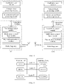
- FIG. 2 shows a diagram of an internal structure of an AP.
- the AP may have multiple antennas or may have a single antenna.
- the AP includes a physical layer (physical layer, PHY) processing circuit and a media access control (media access control, MAC) processing circuit.
- the physical layer processing circuit may be configured to process a physical layer signal
- the MAC layer processing circuit may be configured to process a MAC layer signal.
- An STA product is usually a terminal product, for example, a mobile phone, or a notebook computer, that supports the 802.11 series standards.
- FIG. 3 shows a diagram of a structure of a STA with a single antenna. In an actual scenario, the STA may alternatively have multiple antennas, and may be a device with more than two antennas.
- the STA may include a PHY processing circuit and a MAC processing circuit.
- the physical layer processing circuit may be configured to process a physical layer signal
- the MAC layer processing circuit may be configured to process a MAC layer signal.
- FIG. 2 and FIG. 3 are merely simple schematic diagrams, and do not constitute any limitation on the protection scope of this application.
- internal structures of the AP and the STA refer to descriptions of the conventional technology, or refer to internal structures of an AP and a STA after future technology development, or may be in a form shown in FIG. 4.
- FIG. 4 is a diagram of structures of an AP and a STA according to an embodiment of this application.
- FIG. 4 is a diagram of internal structures of the AP and the STA.
- the AP and/or the STA may be configured with multiple antennas.
- the internal structures of the AP and the STA are not limited in this application, and details are not described again.
- the OFDMA technology is further used in the IEEE 802.11ax standard based on an existing OFDM technology.
- the OFDMA technology is developed based on the OFDM technology.
- the OFDMA technology is a combination of the OFDM technology and a frequency division multiple access (frequency division multiple access, FDMA) technology and is applicable to multi-user access.
- the technology has been adopted by international standards such as LTE and 5G due to its simple implementation and high spectrum utilization.
- a physical channel is divided into multiple resource blocks, each resource block includes multiple subcarriers (subchannels), and each user may occupy one resource block for data transmission. Therefore, multiple users may perform parallel transmission, to reduce time overheads and a conflict probability of contention-based access of multiple users.
- OFDMA technology because subcarriers overlap with each other, spectrum utilization is greatly improved.
- an IEEE 802.11ax standard worker expands, in an IEEE 802.11ax project authorization application (project authorization request, PAR), an operating frequency band range of an IEEE 802.11ax-compliant device from 2.4 GHz and 5 GHz to 2.4 GHz, 5 GHz, and 6 GHz.
- the IEEE 802.11ax standard Due to an increasingly high user requirement for quality of service of communication, it is difficult for the IEEE 802.11ax standard to meet user requirements in terms of a large throughput, low jitter, a low latency, and the like. Therefore, a next-generation IEEE technology, for example, the IEEE 802.11be standard, urgently needs to be developed.
- a device in the IEEE 802.11 next-generation standard needs to be forward compatible, to be specific, compatible with the IEEE 802.11ax standard and an earlier standard. Therefore, the device in the IEEE 802.11 next-generation standard also supports an operating frequency band of an IEEE 802.11ax-compliant device. For example, the device in the IEEE 802.11 next-generation standard supports frequency bands such as 2.4 GHz, 5 GHz, and 6 GHz.
- channel division may be performed based on the latest free 6 GHz frequency band, so that a supported bandwidth may exceed a maximum bandwidth 160 MHz (for example, 320 MHz) supported at 5 GHz.
- a peak throughput may be improved through cooperation of multiple channels and the like, and a service transmission delay may be reduced.
- a device in the IEEE 802.11ax next-generation standard may further improve the peak throughput in a manner such as cooperation of multiple frequency bands (2.4 GHz, 5 GHz, and 6 GHz).
- multiple frequency bands or multiple channels are collectively referred to as multiple links.
- Multi-link device multi-link device, MLD
- a next-generation IEEE 802.11 standard station device that supports multiple links is referred to as a multi-link device.
- two multi-link devices each include multiple STAs, and each STAin one multi-link device may set up a link to one STA in the other multi-link device for communication.
- two multi-link devices each include multiple APs, and each AP in one multi-link device may set up a link to one AP in the other multi-link device for communication.
- one of two multi-link devices includes multiple STAs, and the other multi-link device includes multiple APs.
- Each STA in the multi-link device may set up a link to one AP in the other multi-link device for communication.
- FIG. 5 is a schematic diagram of setting up links between a multi-link AP and a multi-link STA.
- the multi-link AP includes N AP entities (an AP #1, an AP #2, and an AP #N shown in FIG. 5 ).
- the multi-link STA includes N STA entities (a STA#1, a STA #2, and a STA #N shown in FIG. 5 ).
- the N STA entities may share a MAC layer.
- the AP #1 in the multi-link AP communicates with the STA #1 in the multi-link STA over a link (a link #1 shown in FIG. 5 ).
- the AP #2 in the multi-link AP communicates with the STA #2 in the multi-link STA over a link (a link #2 shown in FIG. 5 ).
- the AP #N in the multi-link AP communicates with the STA #N in the multi-link STA over a link (a link #N shown in FIG. 5 ).
- a device in the IEEE 802.11 next-generation standard not only uses continuous ultra-large bandwidth of the new frequency band 6 GHz, but may also use a multi-link cooperation technology to aggregate multiple discontinuous links to form ultra-large bandwidth.
- the multi-link cooperation technology may further be used to simultaneously send a data packet of a same service to a same station.
- the IEEE 802.11ax next-generation standard needs to define a TID-to-link mapping mechanism, to indicate links to which one or more TIDs (in the IEEE 802.11ax, there are a total of eight types of services transmitted based on enhanced distributed channel access (enhanced distributed channel access, EDCA)) are respectively mapped for transmission.
- EDCA enhanced distributed channel access
- each TID can be transmitted over any link.
- each TID can only be transmitted over one or more links to which the TID is mapped.
- an OFDMA technology is introduced into IEEE 802.11ax.
- a STA needs to report an uplink service to an AP, to help the AP correctly allocate a resource block size when scheduling uplink OFMDA transmission.
- An uplink service report mechanism specified in an existing protocol is that when sending a quality of service (quality of service, QoS) data frame (the QoS data frame in this application includes a QoS null data frame), a STA includes BSR signaling in a high throughput control (high throughput control, HT-control) field in a MAC header.
- the HT-control field is 4 bytes, the 4 bytes carry 2-bit indication information, and the indication information indicates that HT-control is high throughput (high throughput, HT) control signaling, or very high throughput (very high throughput, VHT) control signaling, or high efficiency (high efficiency, HE) control signaling.
- each type of control information includes a 4-bit control identifier (control ID), control information, and zero or more padding bits.
- control ID control identifier
- control information control information
- zero or more padding bits The control identifier is used to identify a type of the control signaling, and the control identifier is closely followed by corresponding control information.
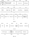
- FIG. 6 is a schematic diagram of a format of BSR signaling. It can be learned from FIG. 6 that BSR information includes an access category identifier (access category identifier, ACI) bitmap (ACI bitmap) field, a delta TID (delta TID) field, an ACI high (ACI high) field, a scaling factor (scaling factor) field, a queue size high (queue size high) field, and a queue size all (queue size all) field.
- a queue in this application is understood as buffer.
- a function of each field in the BSR information is described in detail as follows:
- Size of the buffered service Value of the queue size field + 1 * Value of the scaling factor field
- the value of the queue size field includes a value of the queue size high field or a value of the queue size all field.
- the calculated value is the size of the buffered service of the AC corresponding to the high-priority ACI.
- the calculated value is the total size of the buffered services of all the ACs.
- the queue size field is equal to 254, it indicates that a size of a corresponding buffered service is greater than 254 ⁇ a scaling factor. If the queue size field is equal to 255, it indicates that a size of a corresponding buffered service is unknown.
- the buffer status report mechanism in IEEE 802.11ax is AC-based reporting.
- a multi-link AP cannot determine, based on a service of a specific AC, a size of a service that is of a multi-link STA and that is on each link, and therefore cannot efficiently perform uplink multi-station scheduling.
- indicate may include “directly indicate” and “indirectly indicate”.
- the indication information may directly indicate A or indirectly indicate A, but it does not necessarily indicate that the indication information carries A.
- the information indicated by the indication information is referred to as to-be-indicated information.
- there are multiple manners of indicating the to-be-indicated information for example, but not limited to, the following manners:
- the to-be-indicated information is directly indicated, for example, the to-be-indicated information or an index of the to-be-indicated information is indicated.
- the to-be-indicated information may alternatively be indirectly indicated by indicating other information, where there is an association relationship between the other information and the to-be-indicated information. Alternatively, only a part of the to-be-indicated information may be indicated, and the other part of the to-be-indicated information is known or pre-agreed on.
- specific information may alternatively be indicated by using an arrangement sequence of multiple pieces of information that is pre-agreed on (for example, stipulated in a protocol), to reduce indication overheads to some extent.
- a common part of all pieces of information may be further identified and indicated in a unified manner, to reduce indication overheads caused by separately indicating same information.
- first”, “second”, and various numerical numbers (for example, “#1", and “#2") shown in this application are merely for ease of description, and are used for distinguishing between objects, but are not intended to limit the scope of embodiments of this application.
- the numbers are used for distinguishing between different information, or distinguishing between different STAs, but are not used for describing a particular order or sequence. It should be understood that the objects described in this way are interchangeable in a proper circumstance, so that a solution other than embodiments of this application can be described.
- preset may include “indicated by a device by using signaling” or "predefined”, for example, “defined in a protocol”.
- Predefined may be implemented by storing corresponding code or a table in a device (for example, the device includes a station and an access point) in advance, or may be implemented in another manner that can indicate related information.
- a specific implementation of "predefined” is not limited in this application. For example, “predefined” may be “defined in a protocol”.
- "storage” in embodiments of this application may be storage in one or more memories.
- the one or more memories may be separately disposed, or may be integrated into an encoder, a decoder, a processor, or a communication apparatus.
- a part of the one or more memories may be separately disposed, and a part of the one or more memories are integrated into the translator, the processor, or the communication apparatus.
- a type of the memory may be a storage medium in any form, and this is not limited in this application.
- protocol may be a standard protocol in the communication field, for example, may include an LTE protocol, an NR protocol, a WLAN protocol, and a related protocol applied to a subsequent communication system. This is not limited in this application.
- this application provides a data transmission method, which is applicable to a buffer status report mechanism of a multi-link device.
- Embodiments of this application may be applied to multiple different scenarios, including but not limited to the scenario shown in FIG. 1 .
- a STA may be used as a transmit end, and an AP may be used as a receive end.
- the AP may be used as a transmit end, and the STA may be used as a receive end.
- the STA may be used as a receive end.
- one AP may be used as a transmit end, and the other AP may be used as a receive end.
- one STA may be used as a transmit end, and the other STA may be used as a receive end. Therefore, the following describes embodiments of this application based on a transmit end device and a receive end device.
- a specific structure of an execution body of a method provided in embodiments of this application is not specifically limited in the following embodiments, provided that a program that records code of the method provided in embodiments of this application can be run to perform communication according to the method provided in embodiments of this application.
- the method provided in embodiments of this application may be performed by the receive end device or the transmit end device, or a functional module that is in the receive end device or the transmit end device and that can invoke a program and execute the program.
- the data transmission method provided in embodiments of this application is described in detail below by using interaction between a transmit end device and a receive end device as an example.
- the transmit end device and the receive end device in embodiments of this application are multi-link devices.
- a data transmission manner between multi-link devices is shown in FIG. 5 , and details are not described herein again.
- FIG. 7 is a schematic flowchart of a data transmission method 700 according to an embodiment of this application.
- the method 700 shown in FIG. 7 may include some or all of the following steps.
- a multi-link transmit end determines BSR signaling.
- the BSR signaling indicates a multi-link receive end to schedule a station of the multi-link transmit end over one or more links. For example, OFDMA scheduling is performed.
- how the multi-link receive end performs station scheduling based on the BSR signaling is not limited.
- a multi-link receive end schedules a user station based on BSR signaling reported by a multi-link transmit end in an existing protocol A difference between station scheduling performed by the multi-link receive end in this embodiment of this application and station scheduling performed by a receive end in the conventional technology lies in that the multi-link receive end in this embodiment of this application may schedule the station of the multi-link transmit end over the one or more links.
- For scheduling on each link refer to station scheduling specified in the existing protocol.
- the multi-link transmit end can determine, based on a size of a locally buffered service and a mapping relationship between multiple links and a TID, a format of the BSR signaling sent to the multi-link receive end.
- FIG. 8 is a schematic diagram of the BSR signaling according to an embodiment of this application.
- the BSR signaling includes one or more of a queue size all field of a transmission link, a scaling factor field of the transmission link, a TID field, a queue size field, and a first scaling factor field.
- a queue size all field of a transmission link includes one or more of a queue size all field of a transmission link, a scaling factor field of the transmission link, a TID field, a queue size field, and a first scaling factor field.
- Size of the first buffered service Value of the queue size all field of the transmission link + 1 * Value of the scaling factor field of the transmission link
- the scaling factor field of the transmission link indicates a unit (for example, 16 bytes, 256 bytes, 2048 bytes, or 32768 bytes) of the size of the first buffered service indicated by the queue size all field of the transmission link.
- the queue size field indicates a size of a second buffered service that is corresponding to the first service type indicated by the TID field and that is included in buffered services of the transmit end.
- Size of the second buffered service Value of the queue size field + 1 * Value of the first scaling factor field
- the value of the first scaling factor field indicates a unit (for example, 16 bytes, 256 bytes, 2048 bytes, or 32768 bytes) of the size of the second buffered service indicated by the queue size field.
- Q_T 2 (q_T) - 2
- Q_TID 2 (q_TID) - 2
- Q_T represents the value of the queue size all field of the transmission link
- q_T represents a quantity of bits of the queue size all field of the transmission link
- Q_TID represents the value of the queue size field
- q_TID represents a quantity of bits of the queue size field.
- a quantity of bits occupied by each field included in the BSR signaling in FIG. 8(a) is merely an example, and does not constitute any limitation on the protection scope of this application.
- the quantity of bits occupied by each field included in the BSR signaling may alternatively be another value.
- the queue size all field of the transmission link included in the BSR signaling in FIG. 8(a) may occupy 9 bits or 11 bits.
- the quantity of bits occupied by each field can represent a value of each field.
- a specific quantity is not limited, and examples are not enumerated herein.
- the BSR signaling includes one or more of a first TID field (a TID #1 field shown in FIG. 8(b) ), a first queue size field (a queue #1 size field shown in FIG. 8(b) ), a TID #2 field, a second queue size field (a queue #2 size field shown in FIG. 8(b) ), and a second scaling factor field.
- a first TID field a TID #1 field shown in FIG. 8(b)
- a first queue size field a queue #1 size field shown in FIG. 8(b)
- a TID #2 field a second queue size field
- a second scaling factor field a second scaling factor field
- Size of the third buffered service Value of the queue #1 size field + 1 * Value of the second scaling factor field
- the TID #2 field indicates a currently reported third service type.
- the queue #2 size field indicates a size that is of a fourth buffered service corresponding to the third service type indicated by the TID #2 field and that is included in the buffer of the transmit end.
- the value of the second scaling factor field indicates units (for example, 16 bytes, 256 bytes, 2048 bytes, and 32768 bytes) of the size of the third buffered service and the size of the fourth buffered service.
- Q_1 represents the value of the queue #1 size field
- q_1 represents a quantity of bits of the size field of the queue #1
- Q_2 represents the value of the queue #2 size field
- q_2 represents a quantity of bits of the queue #2 size field.
- a quantity of bits occupied by each field included in the BSR signaling in FIG. 8(b) is merely an example, and does not constitute any limitation on the protection scope of this application.
- the quantity of bits occupied by each field included in the BSR signaling may alternatively be another value.
- the queue #1 size field included in the BSR signaling in FIG. 8(b) may occupy less than or greater than 9 bits.
- the quantity of bits occupied by each field can represent a value of each field.
- a specific quantity is not limited, and examples are not enumerated herein.
- Size of the fifth buffered service Value of the queue # 1 size field + 1 * Value of a scaling factor field
- a value of the third scaling factor field indicates a unit (for example, 16 bytes, 256 bytes, 2048 bytes, or 32768 bytes) of the size of the fifth buffered service indicated by the queue #1 size field.
- the queue #2 size field indicates a size that is of a sixth buffered service corresponding to the fifth service type indicated by the TID #2 field and that is included in the buffer of the transmit end.
- the scaling factor difference field and the third scaling factor field jointly indicate a unit that is of the size of the sixth buffered service and that is indicated by the queue #2 size field.
- the scaling factor difference field when the scaling factor difference field is set to a first value (for example, 0), the unit that is of the size of the sixth buffered service and that is indicated by the queue #2 size field is indicated by using the scaling factor field. This is corresponding to the foregoing calculation manner of the formula 7.
- the scaling factor difference field is set to a second value (for example, 1), the unit that is of the size of the sixth buffered service and that is indicated by the queue #2 size field is a larger value following the unit indicated by the scaling factor field. This is corresponding to the foregoing calculation manner of the formula 8.
- a specific manner of calculating a size that is of a buffered service corresponding to a service type indicated by the TID#2 field and that is indicated by the queue #2 size field in the buffer of the transmit end may be another calculation manner. Details are not described herein again.
- the format of the BSR signaling determined by the multi-link transmit end may include one or more signaling fields mentioned in each of the foregoing three manners.
- the multi-link transmit end needs to learn, based on a mapping relationship between a TID and multiple links (TID-to-link), links over which buffered services indicated by different TIDs are sent.
- the mapping relationship that is between the TID and the multiple links and that is learned by the multi-link transmit end may be determined by negotiating with the receive end.
- the multi-link transmit end sends a request message to the multi-link receive end, where the request message is used for requesting to negotiate the TID-to-link mapping relationship.
- the multi-link receive end sends a response message to the multi-link transmit end, where the response message is used for responding to the negotiated TID-to-link mapping relationship.
- the method shown in FIG. 7 further includes: S711: The transmit end sends the request message to the receive end. S712: The receive end sends the response message to the transmit end.
- the request message is a request management frame
- the response message is a response management frame.
- the multi-link transmit end receives an acknowledgment (acknowledge, ACK) frame returned by the multi-link receive end.
- the multi-link receive end receives an ACK frame returned by the multi-link transmit end.
- the transmit end and the receive end complete negotiation of the TID-to-link mapping relationship.
- TID-to-link mapping negotiation may alternatively be performed in a block acknowledgment setup session, the request message is an ADDBA request frame, and the response message is an ADDBA response frame.
- MAC protocol data unit MAC protocol data unit, MPDU
- MPDU MAC protocol data unit
- the request message and the response message are other frames, for example, management frames used for negotiating the TID-to-link mapping relationship.
- the multi-link transmit end may learn the TID-to-link mapping relationship between the TID and the multiple links through protocol predefinition.
- the multi-link transmit end and the multi-link receive end do not need to determine the mapping relationship by using the foregoing negotiation process.
- the request message is a request management frame and the response message is a response management frame to describe negotiation of a TID-To-Link mapping relationship between the multi-link transmit end and the multi-link receive end.
- the request management frame and the response management frame each carry information related to the TID-to-link mapping relationship between the TID and the multiple links.
- the information related to the TID-to-link mapping relationship includes control information and one or more pieces of mapping information.
- the control information is used for controlling how to set up the TID-to-link mapping relationship, and the mapping information indicates the TID-to-link mapping relationship.
- the control information includes at least one of the following possibilities: Possibility 1: When the request management frame carries a TID-to-link mapping control information field with a value of 0, it indicates that a TID-to-Link mapping is requested (request TID-to-link mapping). The control information field is used for requesting to set up the TID-to-link mapping. In the possibility 1, the multi-link transmit end requests to set up the TID-to-link mapping, and mapping information may be "null" or a special value (for example, 0).
- Possibility 2 When the request management frame carries a TID-to-link mapping control information field with a value of 1, it indicates that a TID-to-Link mapping is suggested (suggest TID-to-link mapping). The control information field is used for suggesting a mapping relationship to be set up. In the possibility 2, the multi-link transmit end requests to set up the TID-to-link mapping relationship and provides the suggested TID-to-link mapping relationship. If the suggested TID-to-link mapping relationship is not satisfied, negotiation for setting up the TID-to-link mapping relationship is still accepted.
- Possibility 3 When the request management frame carries a TID-to-link mapping control information field with a value of 2, it indicates that a TID-to-link mapping is demanded (demand TID-to-link mapping).
- the control information field is used for demanding to set up a specific TID-to-link mapping relationship.
- the multi-link transmit end requests to set up the TID-to-link mapping relationship, and provides the demanded TID-to-link mapping relationship. If the demanded TID-to-link mapping relationship is not satisfied, negotiation for setting up the TID-to-link mapping relationship is not accepted.
- Possibility 4 When the response management frame carries a TID-to-link mapping control information field with a value of 3, it indicates that a TID-to-link mapping is accepted (accept TID-to-link mapping), and the control information field is used for accepting setup of the TID-to-link mapping relationship.
- the multi-link receive end receives a TID-to-link mapping relationship setup request sent by the multi-link transmit end, but TID-to-link mapping information is sent by the multi-link receive end, that is, carried in the response management frame.
- Possibility 5 When the response management frame carries a TID-to-link mapping control information field with a value of 4, it indicates that a TID-to-link mapping is alternated (alternate TID-to-link mapping).
- the control information field is used for alternating the TID-to-link mapping relationship.
- a TID-to-link mapping relationship suggested by the multi-link receive end is different from a suggested TID-to-link mapping relationship or a demanded TID-to-link mapping relationship sent by the multi-link transmit end.
- Possibility 6 When the response management frame carries a TID-to-link mapping control information field with a value of 5, it indicates that a TID-to-link mapping is dictated (dictateTID-to-link mapping).
- the control information field indicates the TID-to-link mapping.
- a TID-to-link mapping relationship demanded by the multi-link receive end is different from a suggested TID-to-link mapping relationship or a demanded TID-to-link mapping relationship sent by the multi-link transmit end.
- Possibility 7 When the response management frame carries a TID-to-link mapping control information field with a value of 6, it indicates that a TID-to-link mapping is rejected (reject TID-to-link mapping).
- the control field information is used for rejecting to set up the TID-to-link mapping relationship.
- the multi-link receive end rejects a TID-to-link mapping setup request sent by the multi-link transmit end.
- the foregoing possibility 1 to possibility 7 may be represented by using the following Table 1: Table 1 Value of a TID-to-link mapping control information field Control information name Description of a transmit end that sends a request management frame Description of a receive end that sends a response management frame 0 Request TID-to-link mapping The multi-link transmit end requests a TID-to-link mapping, and TID-to-link mapping information is 0. None 1 Suggest TID-to-link mapping The multi-link transmit end requests a TID-to-link mapping and provides a suggested TID-to-link mapping. If the suggested TID-to-link mapping is not satisfied, TID-to-link mapping negotiation is still accepted.
- the multi-link transmit end requests a TID-to-link mapping and provides a demanded TID-to-link mapping. If a suggested TID-to-link mapping that is demanded is not satisfied, TID-to-link mapping negotiation is not accepted. None 3 Accept TID-to-link mapping None The multi-link receive end accepts a TID-to-link mapping request sent by the multi-link transmit end, but TID-to-link mapping information is sent by the receive end. 4 Alternate TID-to-link mapping None TID-to-link mapping information suggested by the multi-link receive end is different from suggested TID-to-link mapping information or demanded TID-to-link mapping information sent by the multi-link transmit end.
- TID-to-link mapping None TID-to-link mapping information demanded by the multi-link receive end is different from suggested TID-to-link mapping information or demanded TID-to-link mapping information sent by the multi-link transmit end. 6 Reject TID-to-link mapping None The multi-link receive end rejects a TID-to-link mapping request sent by the multi-link transmit end.
- TID-to-link mapping information includes the following possibilities:
- the TID-to-link mapping information includes N link identifier bitmaps, and N is a positive integer.
- Each link identifier bitmap is corresponding to one TID, a length of the link identifier bitmap is fixed, and a bit whose value is 1 in the link identifier bitmap indicates that a TID corresponding to the link identifier bitmap is corresponding to a link identified by a position of the bit whose value is 1 in the bitmap, so that a TID-to-link mapping is set up.
- the TID-to-link mapping information includes eight link identifier bitmaps, which are 11000000, 10000000, 11100000, 11000000, 10100000, 11000000, 10000000, and 10000000.
- 11000000 is corresponding to a TID #1, and a bit whose value is 1 in 11000000 is located in a first bit and a second bit in the bitmap. In this case, it indicates that the TID #1 is mapped to a link #1 and a link #2.
- a TID #2 is mapped to the link #1
- a TID #3 is mapped to the link #1
- a TID #4 is mapped to the link #1 and the link #2
- a TID #5 is mapped to the link #1 and the link #3
- a TID #6 is mapped to the link #1 and the link #2
- a TID #7 is mapped to the link #1
- a TID #8 is mapped to the link #1.
- the TID corresponding to the link identifier bitmap is corresponding to the link indicated by the position of the bit whose bit value is 1 in the link identifier bitmap is merely an example, and does not constitute any limitation on the protection scope of this application. For example, a position of a bit whose bit value is 0 is located may be determined, to determine a link corresponding to the TID. Details are not described herein again.
- the TID-to-link mapping information includes a control field and N link identifier bitmap fields, and N is a positive integer.
- the control field includes a quantity of TIDs that need to be mapped or a TID bitmap.
- the control field may further include a quantity of links.
- the quantity of links may be located in another position in a multi-link setup request frame and/or a multi-link setup response frame. This is not limited in this application.
- a field of the link identifier bitmap field depends on the quantity of TIDs that need to be mapped or depends on a quantity of bits that are set to a first value in the TID bitmap (for example, a quantity of bits that are set to 1 in the TID bitmap).
- a length of the link identifier bitmap field may be determined by the quantity of links, or may be a fixed length.
- a TID that does not need to be mapped implicitly indicates that the TID can be transmitted over all links, where all the links are links set up in a multi-link setup process.
- a link identifier bitmap further needs to include a corresponding TID identifier number. If the TID-to-link mapping information includes the TID bitmap, a link identifier bitmap does not need to include a link identifier number.
- the TID bitmap is 11000000, the quantity of links is 3, and two link identifier bitmap fields are 110 and 101, it indicates that a TID #1 is mapped to a link #1 and a link #2, a TID #2 is mapped to the link #1 and a link #3, and a TID #3 to a TID #8 are mapped to all links (the link #1, the link #2, and the link #3).
- the quantity of TIDs is 2, the quantity of links is 3, and two link identifier bitmap fields are TID #1 110 101 and TID #2 101, where a TID #1 and a TID #2 also need to be indicated by using a sequence, and are indicated by using four bits or three bits. If the TID# 1 is 0000, and the TID #2 is 0001, it indicates that TID #1 is mapped to a link #1 and a link #2, and the TID #2 is mapped to the link #1 and a link #3, a TID #3 to a TID #8 are mapped to all links (the link #1, the link #2, and the link #3).
- the length of the link identifier bitmap field (excluding a TID identifier) is fixed, for example, is 8 bits.
- bits of the TID bitmap are all set to a second value (for example, the bits of the TID bitmap are all set to 0), it indicates that each TID is mapped to all the links.
- the TID-to-link mapping information may alternatively include multiple TID bitmaps and multiple link identifiers, a quantity of TID bitmaps is equal to a quantity of links, and each TID bitmap is 8 bits.
- Each TID bitmap indicates which TIDs are mapped to a corresponding link.
- the quantity of links is 2, two TID bitmaps are 11110000 and 00001111, two link identifiers are a link #2 and a link #3, where the link identifiers may be represented by multiple bits. In this case, it indicates that a TID #1 to a TID #4 are mapped to the link #2, and a TID #5 to a TID #8 are mapped to the link #3.
- the TID-to-link mapping relationship may be changed later.
- the multi-link transmit end and the multi-link receive end may re-negotiate a second TID-to-link mapping relationship, for example, re-negotiate by using another management frame.
- the first TID-to-link mapping relationship may be different from the second TID-to-link mapping relationship.
- the foregoing process of negotiating, by the multi-link transmit end and the multi-link receive end, to set up the TID-to-link mapping relationship may be independently applied. In other words, there is no need to limit that BSR signaling needs to be transmitted between the multi-link transmit end and the multi-link receive end after the multi-link transmit end and the multi-link receive end negotiate to set up the TID-to-link mapping relationship.
- the multi-link transmit end needs to send the BSR to the multi-link receive end. That is, the method procedure shown in FIG. 7 further includes S720: The multi-link transmit end sends the BSR to the multi-link receive end.
- the multi-link transmit end sends the BSR signaling to the multi-link receive end over the one or more links.
- the multi-link transmit end may send the BSR to the multi-link receive end by sending a data packet carrying the BSR to the multi-link receive end, where a MAC header of the data packet carries the BSR.
- the data packet may be a QoS data packet.
- the QoS data packet in this embodiment of this application includes a QoS null (Null) data packet.
- the multi-link transmit end may actively send the BSR to the multi-link receive end.
- the multi-link transmit end when sending a data packet to the multi-link receive end, the multi-link transmit end carries the BSR signaling in a MAC header of the data packet.
- the multi-link transmit end may be triggered to send the BSR to the multi-link receive end.
- the method procedure shown in FIG. 7 further includes S721: The multi-link receive end sends trigger information to the multi-link transmit end, where the trigger information is used for triggering the multi-link transmit end to report the BSR.
- the multi-link transmit end when receiving a BAR request frame sent by the multi-link receive end, for example, a BAR request frame similar to an 802.11 BSR poll trigger frame, responds with the BSR signaling after a time period of a short interframe space (short interframe space, SIFS).
- SIFS short interframe space
- the multi-link transmit end in addition to sending the BSR signaling to the multi-link receive end, the multi-link transmit end further needs to send buffer status indication information to the multi-link transmit end.
- the data packet further includes the buffer status indication information.
- the buffer status indication information indicates a buffer status of the multi-link transmit end.
- the QoS control field includes: a TID field, an end of service period (end of service period, EOSP) field, an acknowledgment policy (ACK policy) field, an aggregate media access control service data unit (aggregate medium access control service data unit, A-MSDU) present (present) field, a scaling factor field, and a queue size field.
- 1-bit most significant bit in the TID field is reused to indicate, together with an 8-bit queue size field, a buffer size of a service indicated by the TID field.
- This application further provides a method for extending a bitmap of a block acknowledgment frame.
- the transmit end and a receive end Before a transmit end sends a data packet, the transmit end and a receive end usually need to set up a block acknowledgment session, and then the transmit end can send aggregation of multiple data packets. When receiving the aggregation of the multiple data packets, the receive end responds with a block acknowledgment (block Ack) or a multi-STA block acknowledgment (multi-STA block Ack).
- block Ack block acknowledgment
- multi-STA block Ack multi-STA block acknowledgment
- the block acknowledgment session is completed by exchanging an add block acknowledgment (add block acknowledgment, ADDBA) request frame and an ADDBA response frame between the transmit end and the receive end.
- the transmit end sends the ADDBA request frame, and the receive end responds with an acknowledgment frame Ack.
- the receive end returns the ADDBA response frame, and the receive end responds with an acknowledgment frame Ack.
- the transmit end and the receive end exchange the ADDBA request frame and the ADDBA response frame
- the transmit end maintains a transmit window based on content carried in the frames
- the receive end maintains a receive window (or referred to as a scoreboard) and a buffer reordering space based on content carried in the ADDBA request frame and the ADDBA response frame.
- the ADDBA request frame and the ADDBA response frame are a type of function management frames, and include content shown in Table 2 and Table 3.
- Table 2 and Table 3 For specific meanings of the content included in the ADDBA request frame and the ADDBA response frame, refer to the 802.11-2016 standard protocol. Details are not described in this application.
- the block acknowledgment parameter set field includes fields such as an aggregate MAC protocol data unit (aggregate MAC protocol data unit, A-MSDU) support field, a block acknowledgment policy field, a service type field, and a buffer size field.
- FIG. 10 is a schematic diagram of a block acknowledgment parameter set field.
- a type related function of a multi-link block acknowledgment session may be added to a block acknowledgment function field.
- a reserved value in the table 4 below indicates a multi-link block acknowledgment request, a multi-link block acknowledgment response, and multi-link block acknowledgment session teardown.
- FIG. 11 is a schematic diagram of an ADDBA extension element according to an embodiment of this application. It can be seen from FIG. 11 that the ADDBA extension element uses a 10-bit buffer size field in a 1-bit (No-fragmentation (No-fragmentation)), 2-bit (HE fragmentation operation (HE fragmentation operation)), or 5-bit (reserved) joint block acknowledgment parameter set to together indicate a quantity of buffers on a TID indicated by a TID field in the block acknowledgment parameter set.
- No-fragmentation No-fragmentation
- 2-bit HE fragmentation operation
- 5-bit reserved
- a size of each buffered service is equal to a maximum quantity of MSDUs. If the transmit end supports an A-MSDU, a size of each service buffer is equal to a maximum quantity of A-MSDUs.
- An added bit is a most significant bit, and the 10-bit buffer size field of the block acknowledgment parameter set field is a 10-bit least significant bit. Alternatively, a quantity of added bits may be placed in another element (for example, a newly added element), and the quantity of bits may be another quantity of bits, for example, one byte.
- Embodiments of this application provide a data transmission apparatus.
- the apparatus is configured to implement the steps or procedures corresponding to the multi-link receive end in the foregoing method embodiment.
- the apparatus is configured to implement the steps or procedures corresponding to the multi-link transmit end in the foregoing method embodiment.
- FIG. 12 is a schematic block diagram of a data transmission apparatus according to an embodiment of this application.
- the apparatus 1200 may include a communication unit 1210 and a processing unit 1220.
- the communication unit 1210 may communicate with the outside, and the processing unit 1220 is configured to process data.
- the communication unit 1210 may also be referred to as a communication interface or a transceiver unit.
- the apparatus 1200 may implement steps or procedures performed by the multi-link transmit end corresponding to the foregoing method embodiment.
- the processing unit 1220 is configured to perform processing-related operations performed by the multi-link transmit end in the foregoing method embodiment.
- the communication unit 1210 is configured to perform receiving/sending-related operations performed by the multi-link transmit end in the foregoing method embodiment.
- the processing unit 1220 is configured to determine buffer status report BSR signaling, where the BSR signaling indicates a multi-link receive end to schedule a station of a multi-link transmit end over one or more links.
- the communication unit 1210 is configured to send the BSR signaling to the multi-link receive end over the one or more links.
- the multi-link transmit end may be the multi-link STA shown in FIG. 5 .
- the processing unit 1220 may be a processing unit (for example, a processor) in the STA #1 shown in FIG. 5
- the communication unit 1210 may be a communication unit (for example, a transceiver) in the STA #1 shown in FIG. 5 .
- the processing unit 1220 may be a processing unit in the STA #1 and/or the STA #2 shown in FIG.
- the communication unit 1210 may represent communication units in the STA#1 and the STA#2 shown in FIG. 5 .
- the multi-link STA may send the BSR signaling over one or more other links.
- the processing unit 1220 and the communication unit 1210 may represent a processing unit and a communication unit in one or more other STAs. Details are not described herein again.
- the communication unit 1210 is further configured to send a request message to the multi-link receive end, and receive a response message from the multi-link receive end, where the request message and the response message are used for negotiating to set up a traffic identifier-to-link TID-to-link mapping relationship.
- the communication unit 1210 before the communication unit 1210 sends the BSR signaling to the multi-link receive end over the one or more links, the communication unit 1210 is further configured to receive trigger information from the multi-link receive end, where the trigger information is used for triggering the multi-link transmit end to send the BSR signaling over the one or more links.
- the communication unit 1210 sends the BSR signaling to the multi-link receive end over the one or more links includes:
- the communication unit 1210 sends a quality of service QoS data packet to the multi-link receive end over the one or more links, where a media access control MAC header of the QoS data packet carries the BSR signaling.
- the communication unit 1210 may be divided into a receiving unit and a sending unit.
- the receiving unit is configured to perform receiving-related operations of the multi-link transmit end in the foregoing method embodiment
- the sending unit is configured to perform sending-related operations of the multi-link transmit end in the foregoing method embodiment.
- the apparatus 1200 may implement steps or procedures performed by the multi-link receive end in the foregoing method embodiment.
- the communication unit 1210 is configured to perform receiving/sending-related operations performed by the multi-link receive end in the foregoing method embodiment
- the processing unit 1220 is configured to perform processing-related operations performed by the multi-link receive end in the foregoing method embodiment.
- the multi-link receive end may be the multi-link AP shown in FIG. 5 .
- the processing unit 1220 may be a processing unit (for example, a processor) in the AP #1 shown in FIG. 5
- the communication unit 1210 may be a communication unit (for example, a transceiver) in the AP #1 shown in FIG. 5 .
- the processing unit 1220 may be a processing unit in the AP #1 and/or the AP #2 shown in FIG.
- the communication unit 1210 may represent communication units in the AP #1 and the AP #2 shown in FIG. 5 .
- the multi-link AP may receive the BSR signaling over one or more other links.
- the processing unit 1220 and the communication unit 1210 may represent a processing unit and a communication unit in one or more other APs. Details are not described herein again.
- the communication unit 1210 is configured to receive buffer status report BSR signaling from the multi-link transmit end over one or more links.
- the processing unit 1220 is configured to schedule a station of the multi-link transmit end over the one or more links based on the BSR signaling.
- the communication unit 1210 is further configured to receive a request message from the multi-link transmit end, and send a response message to the multi-link transmit end, where the request message and the response message are used for negotiating to set up a traffic identifier-to-link TID-to-link mapping relationship.
- the communication unit 1210 before the communication unit 1210 receives the BSR signaling from the multi-link transmit end over the one or more links, the communication unit 1210 is further configured to send trigger information to the multi-link transmit end, where the trigger information is used for triggering the multi-link transmit end to send the BSR signaling over the one or more links.
- the communication unit 1210 receives BSR signaling from the multi-link transmit end over one or more links includes: The communication unit 1210 receives a quality of service QoS data packet from the multi-link transmit end over the one or more links, where a media access control MAC header of the QoS data packet carries the BSR signaling.
- the communication unit 1210 may be divided into a receiving unit and a sending unit.
- the receiving unit is configured to perform receiving-related operations of the multi-link receive end in the foregoing method embodiment
- the sending unit is configured to perform sending-related operations of the multi-link receive end in the foregoing method embodiment.
- the apparatus 1200 herein is presented in a form of functional units.
- the term "unit" herein may refer to an application-specific integrated circuit (application-specific integrated circuit, ASIC), an electronic circuit, a processor (for example, a shared processor, a dedicated processor, or a group processor) configured to execute one or more software or firmware programs, a memory, a merged logic circuit, and/or another appropriate component that supports the described function.
- ASIC application-specific integrated circuit
- ASIC application-specific integrated circuit
- a processor for example, a shared processor, a dedicated processor, or a group processor
- the apparatus 1200 may be specifically the multi-link transmit end in the foregoing embodiments, and may be configured to perform the procedures and/or steps corresponding to the multi-link transmit end in the foregoing method embodiment.
- the apparatus 1200 may be specifically the multi-link receive end in the foregoing embodiments, and may be configured to perform the procedures and/or steps corresponding to the multi-link receive end in the foregoing method embodiment. To avoid repetition, details are not described herein again.
- the apparatus 1200 in each of the foregoing solutions has functions of implementing corresponding steps performed by the multi-link transmit end in the foregoing method.
- the apparatus 1200 in each of the foregoing solutions has functions of implementing corresponding steps performed by the multi-link receive end in the foregoing method.
- the function may be implemented by hardware, or may be implemented by hardware executing corresponding software.
- the hardware or software includes one or more modules corresponding to the foregoing function.
- a communication unit may be replaced with a transceiver (where for example, a sending unit in the communication unit may be replaced with a transmitter, and a receiving unit in the communication unit may be replaced with a receiver), and another unit such as a processing unit may be replaced with a processor, to separately perform receiving and sending operations and a related processing operation in the method embodiment.
- a transceiver where for example, a sending unit in the communication unit may be replaced with a transmitter, and a receiving unit in the communication unit may be replaced with a receiver
- another unit such as a processing unit may be replaced with a processor, to separately perform receiving and sending operations and a related processing operation in the method embodiment.
- the communication unit may alternatively be a transceiver circuit (where for example, the transceiver circuit may include a receiver circuit and a transmitter circuit), and the processing unit may be a processing circuit.
- the apparatus in FIG. 12 may be the receive end or the transmit end in the foregoing embodiments, or may be a chip or a chip system, for example, a system on chip (system on chip, SoC).
- the communication unit may be an input/output circuit or a communication interface.
- the processing unit is a processor, a microprocessor, or an integrated circuit integrated on the chip. This is not limited herein.
- FIG. 13 shows a data transmission apparatus 1300 according to an embodiment of this application.
- the apparatus 1300 includes a processor 1310 and a transceiver 1320.
- the processor 1310 and the transceiver 1320 communicate with each other through an internal connection path, and the processor 1310 is configured to execute instructions, to control the transceiver 1320 to send a signal and/or receive a signal.
- the apparatus 1300 may further include a memory 1330.
- the memory 1330 communicates with the processor 1310 and the transceiver 1320 through an internal connection path.
- the memory 1330 is configured to store instructions, and the processor 1310 may execute the instructions stored in the memory 1330.
- the apparatus 1300 is configured to implement procedures and steps corresponding to a transmit end in the foregoing method embodiment. In another possible implementation, the apparatus 1300 is configured to implement procedures and steps corresponding to a receive end in the foregoing method embodiment.
- the apparatus 1300 may be specifically the transmit end or the receive end in the foregoing embodiments, or may be a chip or a chip system.
- the transceiver 1320 may be a transceiver circuit of the chip. This is not limited herein.
- the apparatus 1300 may be configured to perform the steps and/or the procedures corresponding to the transmit end or the receive end in the foregoing method embodiment.
- the memory 1330 may include a read-only memory and a random access memory, and provide instructions and data for the processor. A part of the memory may further include a non-volatile random access memory.
- the memory may further store information of a device type.
- the processor 1310 may be configured to execute the instructions stored in the memory. When the processor 1310 executes the instructions stored in the memory, the processor 1310 is configured to perform the steps and/or procedures of the method embodiment corresponding to the transmit end or the receive end.
- steps in the foregoing methods can be implemented by using a hardware integrated logical circuit in the processor, or by using instructions in a form of software.
- the steps of the method disclosed with reference to embodiments of this application may be directly performed by a hardware processor, or may be performed by using a combination of hardware in the processor and a software module.
- a software module may be located in a mature storage medium in the art, such as a random access memory, a flash memory, a read-only memory, a programmable read-only memory, an electrically erasable programmable memory, or a register.
- the storage medium is located in the memory, and a processor reads information in the memory and completes the steps in the foregoing methods in combination with hardware of the processor. To avoid repetition, details are not described herein again.
- the processor in embodiments of this application may be an integrated circuit chip, and has a signal processing capability.
- steps in the foregoing method embodiment can be implemented by using a hardware integrated logical circuit in the processor, or by using instructions in a form of software.
- the processor may be a general purpose processor, a digital signal processor (DSP), an application specific integrated circuit (ASIC), a field programmable gate array (FPGA) or another programmable logic device, a discrete gate or a transistor logic device, or a discrete hardware component.
- DSP digital signal processor
- ASIC application specific integrated circuit
- FPGA field programmable gate array
- the processor in embodiments of this application may implement or perform the methods, the steps, and the logical block diagrams that are disclosed in embodiments of this application.
- the memory in this embodiment of this application may be a volatile memory or a nonvolatile memory, or may include a volatile memory and a nonvolatile memory.
- the nonvolatile memory may be a read-only memory (read-only memory, ROM), a programmable read-only memory (programmable ROM, PROM), an erasable programmable read-only memory (erasable PROM, EPROM), an electrically erasable programmable read-only memory (electrically EPROM, EEPROM), or a flash memory.
- the volatile memory may be a random access memory (random access memory, RAM), used as an external cache.
- RAMs may be used, for example, a static random access memory (static RAM, SRAM), a dynamic random access memory (dynamic RAM, DRAM), a synchronous dynamic random access memory (synchronous DRAM, SDRAM), a double data rate synchronous dynamic random access memory (double data rate SDRAM, DDR SDRAM), an enhanced synchronous dynamic random access memory (enhanced SDRAM, ESDRAM), a synchronous link dynamic random access memory (synchlink DRAM, SLDRAM), and a direct rambus dynamic random access memory (direct rambus RAM, DR RAM).
- static random access memory static random access memory
- DRAM dynamic random access memory
- DRAM dynamic random access memory
- SDRAM synchronous dynamic random access memory
- double data rate SDRAM double data rate SDRAM
- DDR SDRAM double data rate SDRAM
- ESDRAM enhanced synchronous dynamic random access memory
- SLDRAM synchronous link dynamic random access memory
- direct rambus RAM direct rambus RAM
- FIG. 14 shows a data transmission apparatus 1400 according to an embodiment of this application.
- the apparatus 1400 includes a processing circuit 1410 and a transceiver circuit 1420.
- the processing circuit 1410 and the transceiver circuit 1420 communicate with each other through an internal connection path, and the processing circuit 1410 is configured to execute instructions, to control the transceiver circuit 1420 to send a signal and/or receive a signal.
- this application further provides a computer program product.
- the computer program product includes computer program code.
- the computer program code When the computer program code is run on a computer, the computer is enabled to perform the method in the embodiment shown in FIG. 7 .
- this application further provides a computer-readable medium.
- the computer-readable medium stores program code.
- the program code When the program code is run on a computer, the computer is enabled to perform the method in the embodiment shown in FIG. 7 .
- this application further provides a system.
- the system includes the foregoing multi-link transmit end and the foregoing multi-link receive end.
- the disclosed system, apparatus, and method may be implemented in other manners.
- the described apparatus embodiment is merely an example.
- division into the units is merely logical function division and may be other division during actual implementation.
- multiple units or components may be combined or integrated into another system, or some features may be ignored or not performed.
- the displayed or discussed mutual couplings or direct couplings or communication connections may be implemented by using some interfaces.
- the indirect couplings or communication connections between the apparatuses or units may be implemented in electronic, mechanical, or other forms.
- the functions When the functions are implemented in the form of a software functional unit and sold or used as an independent product, the functions may be stored in a computer-readable storage medium. Based on such an understanding, the technical solutions of this application essentially, or the part contributing to the conventional technology, or a part of the technical solutions may be implemented in a form of a software product.
- the computer software product is stored in a storage medium, and includes several instructions for instructing a computer device (which may be a personal computer, a server, a network device, or the like) to perform all or a part of the steps of the methods described in embodiments of this application.
Abstract
Description
- This application claims priority to
Chinese Patent Application No. 202010183125.8, filed with the China National Intellectual Property Administration on March 16, 2020 - This application relates to the field of wireless communication technologies, and more specifically, to a data transmission method and an apparatus.
- Data traffic rapidly grows with development of the mobile Internet and popularization of smart terminals. A wireless local area network (wireless local area network, WLAN) technology with advantages of a high rate and low costs has become one of mainstream mobile broadband access technologies.
- To greatly improve a service transmission rate of a WLAN system, the institute of electrical and electronics engineers (institute of electrical and electronics engineers, IEEE) 802.11ax standard further uses an orthogonal frequency division multiple access (orthogonal frequency division multiple access, OFDMA) technology based on an existing orthogonal frequency division multiplexing (orthogonal frequency division multiplexing, OFDM) technology. The OFDMA technology supports simultaneous data sending and receiving by multiple nodes. In the IEEE 802.11ax standard, a buffer status report (buffer status report, BSR) mechanism may be used for assisting an access point (access point, AP) in uplink OFDMA scheduling.
- An operating frequency band range of an IEEE 802.11ax-compliant device is expanded from 2.4 GHz and 5 GHz to 2.4 GHz, 5 GHz, and 6 GHz. Due to an increasingly high user requirement for quality of service of communication, it is difficult for the IEEE 802.11ax standard to meet user requirements in terms of a large throughput, low jitter, a low latency, and the like. Therefore, a next-generation IEEE technology, for example, the IEEE 802.11be standard, urgently needs to be developed. The IEEE 802.11be standard is referred to as an extremely high throughput (extremely high throughput, EHT) standard. An IEEE 802.11be-compliant device may reduce a service transmission delay through multi-link (multi-link, ML) cooperation.
- However, how to introduce the BSR mechanism to improve performance of scheduling a station by an ML device through ML cooperation becomes an urgent problem to be resolved.
- This application provides a data transmission method and an apparatus, to introduce a BSR mechanism through ML cooperation, to improve performance of scheduling a station by an ML device.
- According to a first aspect, a data transmission method is provided. The data transmission method may be performed by a multi-link transmit end, or may be performed by a chip or a circuit disposed in the multi-link transmit end. This is not limited in this application.
- The multi-link transmit end may be a multi-link station (station, STA), a multi-link AP, or another multi-link device.
- The data transmission method includes:
The multi-link transmit end determines buffer status report BSR signaling, where the BSR signaling is used by a multi-link receive end for scheduling a station of the multi-link transmit end over one or more links. The multi-link transmit end sends the BSR signaling to the multi-link receive end over the one or more links. - According to the data transmission method provided in this embodiment of this application, the multi-link transmit end sends the BSR signaling to the multi-link receive end, so that the multi-link receive end can schedule the station of the multi-link transmit end over the one or more links based on the BSR signaling. This improves, based on a BSR mechanism, performance of scheduling a station by an ML device through multi-link cooperation.
- With reference to the first aspect, in some implementations of the first aspect, the method further includes: The multi-link transmit end sends a request message to the multi-link receive end. The multi-link transmit end receives a response message from the multi-link receive end. The request message and the response message are used for negotiating to set up a traffic identifier-to-link TID-to-link mapping relationship.
- Further, according to the data transmission method provided in this embodiment of this application, before sending the BSR signaling to the multi-link receive end, the multi-link transmit end may further obtain the TID-to-link mapping relationship by negotiating with the multi-link receive end. Service buffer sizes on different links can be determined based on the TID-to-link mapping relationship, so that the multi-link transmit end can more accurately determine, based on the TID-to-link mapping relationship, the BSR signaling that needs to be sent.
- With reference to the first aspect, in some implementations of the first aspect, the BSR signaling includes one or more of a queue size all field of a transmission link, a scaling factor field of the transmission link, a TID field, a queue size field, and a first scaling factor field.
- The queue size all field of the transmission link indicates a size of a first buffered service on a link for sending the BSR signaling, the scaling factor field of the transmission link indicates a unit of the size of the first buffered service, the TID field indicates a reported first service type, the queue size field indicates a size of a second buffered service corresponding to the first service type, and the first scaling factor field indicates a unit of the size of the second buffered service.
- The transmission link indicates a link for transmitting the BSR signaling. To be specific, if a format of the BSR signaling includes the queue size all field of the transmission link, the scaling factor field of the transmission link, the TID field, the queue size field, and the field indicating the unit of the size of the second buffered service, after receiving the BSR signaling, the multi-link receive end can schedule the station of the multi-link transmit end on the transmission link based on the BSR signaling.
- With reference to the first aspect, in some implementations of the first aspect, the BSR signaling includes one or more of a first TID field, a first queue size field, a second TID field, a second queue size field, and a second scaling factor field.
- The first TID field indicates a reported second service type, the first queue size field indicates a size of a third buffered service corresponding to the second service type, the second TID field indicates a reported third service type, the second queue size field indicates a size of a fourth buffered service corresponding to the third service type, and the second scaling factor field indicates a unit of the size of the third buffered service and a unit of the size of the fourth buffered service.
- If the format of the BSR signaling includes the first TID field, the first queue size field, the second TID field, the second queue size field, and the second scaling factor field, after receiving the BSR signaling, the multi-link receive end can schedule the station of the multi-link transmit end on a link corresponding to a first TID and a link corresponding to a second TID based on the BSR signaling.
- With reference to the first aspect, in some implementations of the first aspect, the BSR signaling includes one or more of a third TID field, a third queue size field, a third scaling factor field, a fourth TID field, a fourth queue size field, and a scaling factor difference field.
- The third TID field indicates a reported fourth service type, the third queue size field indicates a size of a fifth buffered service corresponding to the fourth service type, the fourth TID field indicates a reported fifth service type, the fourth queue size field indicates a size of a sixth buffered service corresponding to the fifth service type, the third scaling factor field indicates a unit of the size of the fifth buffered service, and the third scaling factor field and the scaling factor difference field indicate a unit of the size of the sixth buffered service.
- If the BSR signaling format includes the third TID field, the third queue size field, the third scaling factor field, the fourth TID field, the fourth queue size field, and the scaling factor difference field, after receiving the BSR signaling, the multi-link receive end can schedule the station of the multi-link transmit end on a link corresponding to a third TID and a link corresponding to a fourth TID based on the BSR signaling.
- With reference to the first aspect, in some implementations of the first aspect, the request message and/or the response message include/includes control information and mapping information, the control information is used for determining to set up the mapping relationship, and the mapping information indicates the mapping relationship.
- The request message and the response message used for negotiating to set up the TID-to-link mapping relationship include the control information and the mapping information, so that the multi-link transmit end and the multi-link receive end can successfully set up the TID-to-link mapping relationship based on the request message and the response message.
- With reference to the first aspect, in some implementations of the first aspect, a value of the control information includes at least one of the following: 0, 1, 2, 3, 4, 5, or 6. When the value of the control information included in the request message is 0, it indicates that the transmit end requests to set up the mapping relationship. When the value of the control information included in the request message is 1, it indicates that the transmit end requests to set up the mapping relationship and provide a suggested mapping relationship. When the value of the control information included in the request message is 2, it indicates that the transmit end requests to set up the mapping relationship and provide a required mapping relationship. When the value of the control information included in the response message is 3, it indicates that the receive end accepts a request that is for setting up the mapping relationship and that is sent by the transmit end. When the value of the control information included in the response message is 4, it indicates that a mapping relationship suggested by the receive end is different from a mapping relationship suggested or required by the transmit end. When the value of the control information included in the response message is 5, it indicates that a mapping relationship required by the receive end is different from a mapping relationship suggested or required by the transmit end. When the value of the control information included in the response message is 6, it indicates that the receive end rejects the request that is for setting up the mapping relationship and that is sent by the transmit end.
- The control information may be 1-bit information, so that signaling overheads can be reduced.
- With reference to the first aspect, in some implementations of the first aspect, the mapping information includes N link identifier bitmaps, and N is a positive integer.
- According to the data transmission method provided in this embodiment of this application, the mapping information included in the request message and the response message used for negotiating to set up the TID-to-link mapping relationship may be the N link identifier bitmaps. The multi-link transmit end and the multi-link receive end determine the TID-to-link mapping relationship based on the N link identifier bitmaps.
- With reference to the first aspect, in some implementations of the first aspect, the mapping information includes a control field and N link identifier bitmaps, and N is a positive integer.
- According to the data transmission method provided in this embodiment of this application, the mapping information included in the request message and the response message used for negotiating to set up the TID-to-link mapping relationship may be the N link identifier bitmaps and the control field. The multi-link transmit end and the multi-link receive end determine the TID-to-link mapping relationship based on the N link identifier bitmaps and the control field.
- With reference to the first aspect, in some implementations of the first aspect, the request message includes a request management frame, and the response message includes a response management frame. Alternatively, the request message includes an ADDBA request frame, and the response message includes an ADDBA response frame.
- According to the data transmission method provided in this embodiment of this application, the request message and the response message used for negotiating to set up the TID-to-link mapping relationship may reuse signaling in an existing procedure, to reduce signaling overheads.
- With reference to the first aspect, in some implementations of the first aspect, before the multi-link transmit end sends the BSR signaling to the multi-link receive end over the one or more links, the method further includes: The multi-link transmit end receives trigger information from the multi-link receive end, where the trigger information is used for triggering the multi-link transmit end to send the BSR signaling over the one or more links.
- According to the data transmission method provided in this embodiment of this application, the multi-link transmit end may passively determine, based on the trigger information of the multi-link receive end, to send the BSR signaling to the multi-link receive end, to provide an initiative for the multi-link receive end.
- With reference to the first aspect, in some implementations of the first aspect, that the multi-link transmit end sends the BSR signaling to the multi-link receive end over the one or more links includes:
The multi-link transmit end sends a quality of service QoS data packet to the multi-link receive end, where a media access control MAC header of the QoS data packet carries the BSR signaling. - According to the data transmission method provided in this embodiment of this application, the multi-link transmit end may include the BSR signaling in the MAC header of the QoS data packet to send the BSR signaling to the multi-link receive end, to provide a simple manner of sending the BSR signaling.
- With reference to the first aspect, in some implementations of the first aspect, a QoS control field of the QoS data packet further includes buffer status indication information, and the buffer status indication information indicates a size of a buffered service of the multi-link transmit end.
- The QoS data packet carrying the BSR signaling may further carry buffer status indication information that indicates the size of the buffered service of the transmit end, so that the multi-link receive end learns the size of the service locally buffered by the multi-link transmit end.
- With reference to the first aspect, in some implementations of the first aspect, the buffer status indication information includes one bit of a TID field in the QoS control field and eight bits of a queue size field in the QoS control field.
- The buffer status indication information may be implemented by reusing a field in an existing QoS data packet, to reduce signaling overheads.
- According to a second aspect, another data transmission method is provided. The data transmission method may be performed by a multi-link receive end, or may be performed by a chip or a circuit disposed in the multi-link receive end. This is not limited in this application.
- The second device may be a multi-link STA, a multi-link AP, or another multi-link device.
- The data transmission method includes:
The multi-link receive end receives buffer status report BSR signaling from a multi-link transmit end over one or more links. - The multi-link receive end schedules a station of the multi-link transmit end over the one or more links based on the BSR signaling.
- According to the data transmission method provided in this embodiment of this application, the multi-link transmit end sends the BSR signaling to the multi-link receive end, so that the multi-link receive end can schedule the station of the multi-link transmit end over the one or more links based on the BSR signaling. This improves, based on a BSR mechanism, performance of scheduling a station by an ML device through multi-link cooperation.
- With reference to the second aspect, in some implementations of the second aspect, the method further includes: The multi-link receive end receives a request message from the multi-link transmit end. The multi-link receive end sends a response message to the multi-link transmit end. The request message and the response message are used for negotiating to set up a traffic identifier-to-link TID-to-link mapping relationship.
- Further, according to the data transmission method provided in this embodiment of this application, before sending the BSR signaling to the multi-link receive end, the multi-link transmit end may further obtain the TID-to-link mapping relationship by negotiating with the multi-link receive end. Service buffer sizes on different links can be determined based on the TID-to-link mapping relationship, so that the multi-link transmit end can more accurately determine, based on the TID-to-link mapping relationship, the BSR signaling that needs to be sent.
- With reference to the second aspect, in some implementations of the second aspect, the BSR signaling includes one or more of a queue size all field of a transmission link, a scaling factor field of the transmission link, a TID field, a queue size field, and a first scaling factor field.
- The queue size all field of the transmission link indicates a size of a first buffered service on a link for sending the BSR signaling, the scaling factor field of the transmission link indicates a unit of the size of the first buffered service, the TID field indicates a reported first service type, the queue size field indicates a size of a second buffered service corresponding to the first service type, and the first scaling factor field indicates a unit of the size of the second buffered service.
- The transmission link indicates a link for transmitting the BSR signaling. To be specific, if a format of the BSR signaling includes the queue size all field of the transmission link, the scaling factor field of the transmission link, the TID field, the queue size field, and the field indicating the unit of the size of the second buffered service, after receiving the BSR signaling, the multi-link receive end can schedule the station of the multi-link transmit end on the transmission link based on the BSR signaling.
- With reference to the second aspect, in some implementations of the second aspect, the BSR signaling includes one or more of a first TID field, a first queue size field, a second TID field, a second queue size field, and a second scaling factor field.
- The first TID field indicates a reported second service type, the first queue size field indicates a size of a third buffered service corresponding to the second service type, the second TID field indicates a reported third service type, the second queue size field indicates a size of a fourth buffered service corresponding to the third service type, and the second scaling factor field indicates a unit of the size of the third buffered service and a unit of the size of the fourth buffered service.
- If the format of the BSR signaling includes the first TID field, the first queue size field, the second TID field, the second queue size field, and the second scaling factor field, after receiving the BSR signaling, the multi-link receive end can schedule the station of the multi-link transmit end on a link corresponding to a first TID and a link corresponding to a second TID based on the BSR signaling.
- With reference to the second aspect, in some implementations of the second aspect, the BSR signaling includes one or more of a third TID field, a third queue size field, a third scaling factor field, a fourth TID field, a fourth queue size field, and a scaling factor difference field.
- The third TID field indicates a reported fourth service type, the third queue size field indicates a size of a fifth buffered service corresponding to the fourth service type, the fourth TID field indicates a reported fifth service type, the fourth queue size field indicates a size of a sixth buffered service corresponding to the fifth service type, the third scaling factor field indicates a unit of the size of the fifth buffered service, and the third scaling factor field and the scaling factor difference field indicate a unit of the size of the sixth buffered service.
- If the BSR signaling format includes the third TID field, the third queue size field, the third scaling factor field, the fourth TID field, the fourth queue size field, and the scaling factor difference field, after receiving the BSR signaling, the multi-link receive end can schedule the station of the multi-link transmit end on a link corresponding to a third TID and a link corresponding to a fourth TID based on the BSR signaling.
- With reference to the second aspect, in some implementations of the second aspect, the request message and/or the response message include/includes control information and mapping information, the control information is used for determining to set up the mapping relationship, and the mapping information indicates the mapping relationship.
- The request message and the response message used for negotiating to set up the TID-to-link mapping relationship include the control information and the mapping information, so that the multi-link transmit end and the multi-link receive end can successfully set up the TID-to-link mapping relationship based on the request message and the response message.
- With reference to the first aspect, in some implementations of the first aspect, a value of the control information includes at least one of the following: 0, 1, 2, 3, 4, 5, or 6. When the value of the control information included in the request message is 0, it indicates that the transmit end requests to set up the mapping relationship. When the value of the control information included in the request message is 1, it indicates that the transmit end requests to set up the mapping relationship and provide a suggested mapping relationship. When the value of the control information included in the request message is 2, it indicates that the transmit end requests to set up the mapping relationship and provide a demanded mapping relationship. When the value of the control information included in the response message is 3, it indicates that the receive end accepts a request that is for setting up the mapping relationship and that is sent by the transmit end. When the value of the control information included in the response message is 4, it indicates that a mapping relationship suggested by the receive end is different from a mapping relationship suggested or demanded by the transmit end. When the value of the control information included in the response message is 5, it indicates that a mapping relationship demanded by the receive end is different from a mapping relationship suggested or demanded by the transmit end. When the value of the control information included in the response message is 6, it indicates that the receive end rejects the request that is for setting up the mapping relationship and that is sent by the transmit end.
- The control information may be 1-bit information, so that signaling overheads can be reduced.
- With reference to the second aspect, in some implementations of the second aspect, the mapping information includes N link identifier bitmaps, and N is a positive integer.
- According to the data transmission method provided in this embodiment of this application, the mapping information included in the request message and the response message used for negotiating to set up the TID-to-link mapping relationship may be the N link identifier bitmaps. The multi-link transmit end and the multi-link receive end determine the TID-to-link mapping relationship based on the N link identifier bitmaps.
- With reference to the second aspect, in some implementations of the second aspect, the mapping information includes a control field and N link identifier bitmaps, and N is a positive integer.
- According to the data transmission method provided in this embodiment of this application, the mapping information included in the request message and the response message used for negotiating to set up the TID-to-link mapping relationship may be the N link identifier bitmaps and the control field. The multi-link transmit end and the multi-link receive end determine the TID-to-link mapping relationship based on the N link identifier bitmaps and the control field.
- With reference to the second aspect, in some implementations of the second aspect, the request message includes a request management frame, and the response message includes a response management frame. Alternatively, the request message includes an ADDBA request frame, and the response message includes an ADDBA response frame.
- According to the data transmission method provided in this embodiment of this application, the request message and the response message used for negotiating to set up the TID-to-link mapping relationship may reuse signaling in an existing procedure, to reduce signaling overheads.
- With reference to the second aspect, in some implementations of the second aspect, before the multi-link receive end receives the BSR signaling from the multi-link transmit end over the one or more links, the method further includes:
The multi-link receive end sends trigger information to the multi-link transmit end, where the trigger information is used for triggering the multi-link transmit end to send the BSR signaling over the one or more links. - According to the data transmission method provided in this embodiment of this application, the multi-link transmit end may passively determine, based on the trigger information of the multi-link receive end, to send the BSR signaling to the multi-link receive end, to provide an initiative for the multi-link receive end.
- With reference to the second aspect, in some implementations of the second aspect, that the multi-link receive end receives BSR signaling from a multi-link transmit end over one or more links includes:
The multi-link receive end receives a quality of service QoS data packet from the multi-link transmit end over the one or more links, where a media access control MAC header of the QoS data packet carries the BSR signaling. - According to the data transmission method provided in this embodiment of this application, the multi-link transmit end may include the BSR signaling in the MAC header of the QoS data packet to send the BSR signaling to the multi-link receive end, to provide a simple manner of sending the BSR signaling.
- With reference to the second aspect, in some implementations of the second aspect, a QoS control field of the QoS data packet further includes buffer status indication information, and the buffer status indication information indicates a size of a buffered service of the multi-link transmit end.
- The QoS data packet carrying the BSR signaling may further carry buffer status indication information that indicates the size of the buffered service of the transmit end, so that the multi-link receive end learns the size of the service locally buffered by the multi-link transmit end.
- With reference to the second aspect, in some implementations of the second aspect, the buffer status indication information includes one bit of a TID field in the QoS control field and eight bits of a queue size field in the QoS control field.
- The buffer status indication information may be implemented by reusing a field in an existing QoS data packet, to reduce signaling overheads.
- According to a third aspect, a data transmission method is provided. The data transmission method may be performed by a multi-link transmit end, or may be performed by a chip or a circuit disposed in the multi-link transmit end. This is not limited in this application.
- The multi-link transmit end may be a multi-link STA, a multi-link AP, or another multi-link device.
- The data transmission method includes:
The multi-link transmit end sends a request message to a multi-link receive end. - The multi-link transmit end receives a response message from the multi-link receive end.
- The request message and the response message are used for negotiating to set up a traffic identifier-to-link TID-to-link mapping relationship.
- According to the data transmission method provided in this embodiment of this application, before sending BSR signaling to the multi-link receive end, the multi-link transmit end may further obtain the TID-to-link mapping relationship by negotiating with the multi-link receive end. Service buffer sizes on different links can be determined based on the TID-to-link mapping relationship, so that the multi-link transmit end can more accurately determine, based on the TID-to-link mapping relationship, the BSR signaling that needs to be sent.
- With reference to the third aspect, in some implementations of the third aspect, the method further includes: The multi-link transmit end determines buffer status report B SR signaling, where the BSR signaling indicates the multi-link receive end to schedule a station of the multi-link transmit end over one or more links. The multi-link transmit end sends the BSR signaling to the multi-link receive end over the one or more links.
- According to the data transmission method provided in this embodiment of this application, the multi-link transmit end sends the BSR signaling to the multi-link receive end, so that the multi-link receive end can schedule the station of the multi-link transmit end over the one or more links based on the BSR signaling. This improves, based on a BSR mechanism, performance of scheduling a station by an ML device through multi-link cooperation.
- Specifically, a format of the BSR signaling in the third aspect is the same as the format of the BSR signaling in the first aspect. Details are not described herein again.
- With reference to the third aspect, in some implementations of the third aspect, the request message and/or the response message include/includes control information and mapping information, the control information is used for determining to set up the mapping relationship, and the mapping information indicates the mapping relationship.
- The request message and the response message used for negotiating to set up the TID-to-link mapping relationship include the control information and the mapping information, so that the multi-link transmit end and the multi-link receive end can successfully set up the TID-to-link mapping relationship based on the request message and the response message.
- With reference to the third aspect, in some implementations of the third aspect, the mapping information includes N link identifier bitmaps, and N is a positive integer.
- According to the data transmission method provided in this embodiment of this application, the mapping information included in the request message and the response message used for negotiating to set up the TID-to-link mapping relationship may be the N link identifier bitmaps. The multi-link transmit end and the multi-link receive end determine the TID-to-link mapping relationship based on the N link identifier bitmaps.
- With reference to the third aspect, in some implementations of the third aspect, the mapping information includes a control field and N link identifier bitmaps, and N is a positive integer.
- According to the data transmission method provided in this embodiment of this application, the mapping information included in the request message and the response message used for negotiating to set up the TID-to-link mapping relationship may be the N link identifier bitmaps and the control field. The multi-link transmit end and the multi-link receive end determine the TID-to-link mapping relationship based on the N link identifier bitmaps and the control field.
- With reference to the third aspect, in some implementations of the third aspect, the request message includes a request management frame, and the response message includes a response management frame. Alternatively, the request message includes an ADDBA request frame, and the response message includes an ADDBA response frame.
- According to the data transmission method provided in this embodiment of this application, the request message and the response message used for negotiating to set up the TID-to-link mapping relationship may reuse signaling in an existing procedure, to reduce signaling overheads.
- With reference to the third aspect, in some implementations of the third aspect, before the multi-link transmit end sends the BSR signaling to the multi-link receive end over the one or more links, the method further includes: The multi-link transmit end receives trigger information from the multi-link receive end, where the trigger information is used for triggering the multi-link transmit end to send the BSR signaling over the one or more links.
- According to the data transmission method provided in this embodiment of this application, the multi-link transmit end may passively determine, based on the trigger information of the multi-link receive end, to send the BSR signaling to the multi-link receive end, to provide an initiative for the multi-link receive end.
- With reference to the third aspect, in some implementations of the third aspect, that the multi-link transmit end sends the BSR signaling to the multi-link receive end over the one or more links includes:
The multi-link transmit end sends a quality of service QoS data packet to the multi-link receive end, where a media access control MAC header of the QoS data packet carries the BSR signaling. - According to the data transmission method provided in this embodiment of this application, the multi-link transmit end may include the BSR signaling in the MAC header of the QoS data packet to send the BSR signaling to the multi-link receive end, to provide a simple manner of sending the BSR signaling.
- With reference to the third aspect, in some implementations of the third aspect, a QoS control field of the QoS data packet further includes buffer status indication information, and the buffer status indication information indicates a size of a buffered service of the multi-link transmit end.
- The QoS data packet carrying the BSR signaling may further carry buffer status indication information that indicates the size of the buffered service of the transmit end, so that the multi-link receive end learns the size of the service locally buffered by the multi-link transmit end.
- With reference to the third aspect, in some implementations of the third aspect, the buffer status indication information includes one bit of a TID field in the QoS control field and eight bits of a queue size field in the QoS control field.
- The buffer status indication information may be implemented by reusing a field in an existing QoS data packet, to reduce signaling overheads.
- According to a fourth aspect, another data transmission method is provided. The data transmission method may be performed by a multi-link receive end, or may be performed by a chip or a circuit disposed in the multi-link receive end. This is not limited in this application.
- The second device may be a multi-link STA, a multi-link AP, or another multi-link device.
- The data transmission method includes:
The multi-link receive end receives a request message from a multi-link transmit end. The multi-link receive end sends a response message to the multi-link transmit end. The request message and the response message are used for negotiating to set up a traffic identifier-to-link TID-to-link mapping relationship. - According to the data transmission method provided in this embodiment of this application, before sending BSR signaling to the multi-link receive end, the multi-link transmit end may further obtain the TID-to-link mapping relationship by negotiating with the multi-link receive end. Service buffer sizes on different links can be determined based on the TID-to-link mapping relationship, so that the multi-link transmit end can more accurately determine, based on the TID-to-link mapping relationship, the BSR signaling that needs to be sent.
- With reference to the fourth aspect, in some implementations of the fourth aspect, the method further includes: The multi-link receive end receives the buffer status report BSR signaling from the multi-link transmit end over one or more links.
- The multi-link receive end schedules a station of the multi-link transmit end over the one or more links based on the BSR signaling.
- Further, according to the data transmission method provided in this embodiment of this application, the multi-link transmit end sends the BSR signaling to the multi-link receive end, so that the multi-link receive end can schedule the station of the multi-link transmit end over the one or more links based on the BSR signaling. This improves, based on a BSR mechanism, performance of scheduling a station by an ML device through multi-link cooperation.
- Specifically, a format of the BSR signaling in the fourth aspect is the same as the format of the BSR signaling in the second aspect. Details are not described herein again.
- With reference to the fourth aspect, in some implementations of the fourth aspect, the request message and/or the response message include/includes control information and mapping information, the control information is used for determining to set up the mapping relationship, and the mapping information indicates the mapping relationship.
- The request message and the response message used for negotiating to set up the TID-to-link mapping relationship include the control information and the mapping information, so that the multi-link transmit end and the multi-link receive end can successfully set up the TID-to-link mapping relationship based on the request message and the response message.
- With reference to the fourth aspect, in some implementations of the fourth aspect, the mapping information includes N link identifier bitmaps, and N is a positive integer.
- According to the data transmission method provided in this embodiment of this application, the mapping information included in the request message and the response message used for negotiating to set up the TID-to-link mapping relationship may be the N link identifier bitmaps. The multi-link transmit end and the multi-link receive end determine the TID-to-link mapping relationship based on the N link identifier bitmaps.
- With reference to the fourth aspect, in some implementations of the fourth aspect, the mapping information includes a control field and N link identifier bitmaps, and N is a positive integer.
- According to the data transmission method provided in this embodiment of this application, the mapping information included in the request message and the response message used for negotiating to set up the TID-to-link mapping relationship may be the N link identifier bitmaps and the control field. The multi-link transmit end and the multi-link receive end determine the TID-to-link mapping relationship based on the N link identifier bitmaps and the control field.
- With reference to the fourth aspect, in some implementations of the fourth aspect, the request message includes a request management frame, and the response message includes a response management frame. Alternatively, the request message includes an ADDBA request frame, and the response message includes an ADDBA response frame.
- According to the data transmission method provided in this embodiment of this application, the request message and the response message used for negotiating to set up the TID-to-link mapping relationship may reuse signaling in an existing procedure, to reduce signaling overheads.
- With reference to the fourth aspect, in some implementations of the fourth aspect, before the multi-link receive end receives the BSR signaling from the multi-link transmit end over the one or more links, the method further includes:
- The multi-link receive end sends trigger information to the multi-link transmit end, where the trigger information is used for triggering the multi-link transmit end to send the BSR signaling over the one or more links.
- According to the data transmission method provided in this embodiment of this application, the multi-link transmit end may passively determine, based on the trigger information of the multi-link receive end, to send the BSR signaling to the multi-link receive end, to provide an initiative for the multi-link receive end.
- With reference to the fourth aspect, in some implementations of the fourth aspect, that the multi-link receive end receives BSR signaling from a multi-link transmit end over one or more links includes:
The multi-link receive end receives a quality of service QoS data packet from the multi-link transmit end over the one or more links, where a media access control MAC header of the QoS data packet carries the BSR signaling. - According to the data transmission method provided in this embodiment of this application, the multi-link transmit end may include the BSR signaling in the MAC header of the QoS data packet to send the BSR signaling to the multi-link receive end, to provide a simple manner of sending the BSR signaling.
- With reference to the fourth aspect, in some implementations of the fourth aspect, a QoS control field of the QoS data packet further includes buffer status indication information, and the buffer status indication information indicates a size of a buffered service of the multi-link transmit end.
- The QoS data packet carrying the BSR signaling may further carry buffer status indication information that indicates the size of the buffered service of the transmit end, so that the multi-link receive end learns the size of the service locally buffered by the multi-link transmit end.
- With reference to the fourth aspect, in some implementations of the fourth aspect, the buffer status indication information includes one bit of a TID field in the QoS control field and eight bits of a queue size field in the QoS control field.
- The buffer status indication information may be implemented by reusing a field in an existing QoS data packet, to reduce signaling overheads.
- According to a fifth aspect, a data transmission apparatus is provided. The apparatus is configured to perform the methods provided in the first aspect and the third aspect. Specifically, the apparatus may include a module configured to perform any one of the first aspect, the third aspect, and the possible implementations of the first aspect and the third aspect.
- According to a sixth aspect, a data transmission apparatus is provided. The apparatus is configured to perform the methods provided in the second aspect and the fourth aspect. Specifically, the apparatus may include a module configured to perform any one of the second aspect, the fourth aspect, and the possible implementations of the second aspect and the fourth aspect.
- According to a seventh aspect, a data transmission apparatus is provided. The apparatus includes a processor. The processor is coupled to a memory, and may be configured to execute instructions in the memory, to implement the method according to any one of the first aspect, the third aspect, and the possible implementations of the first aspect and the third aspect. Optionally, the apparatus further includes the memory. Optionally, the apparatus further includes a communication interface, and the processor is coupled to the communication interface.
- In an implementation, the apparatus is an access point. When the apparatus is an access point, the communication interface may be a transceiver, or an input/output interface.
- In another implementation, the apparatus is a chip configured in an access point. When the apparatus is a chip configured in an access point, the communication interface may be an input/output interface.
- In an implementation, the apparatus is a station. When the apparatus is a station, the communication interface may be a transceiver, or an input/output interface.
- In another implementation, the apparatus is a chip configured in a station. When the apparatus is a chip configured in a station, the communication interface may be an input/output interface.
- In another implementation, the apparatus is a chip or a chip system.
- Optionally, the transceiver may be a transceiver circuit. Optionally, the input/output interface may be an input/output circuit.
- According to an eighth aspect, a data transmission apparatus is provided. The apparatus includes a processor. The processor is coupled to a memory, and may be configured to execute instructions in the memory, to implement the method according to any one of the second aspect, the fourth aspect, and the possible implementations of the second aspect and the fourth aspect. Optionally, the apparatus further includes the memory. Optionally, the apparatus further includes a communication interface, and the processor is coupled to the communication interface.
- In an implementation, the apparatus is an access point. When the apparatus is an access point, the communication interface may be a transceiver, or an input/output interface.
- In another implementation, the apparatus is a chip configured in an access point. When the apparatus is a chip configured in an access point, the communication interface may be an input/output interface.
- In an implementation, the apparatus is a station. When the apparatus is a station, the communication interface may be a transceiver, or an input/output interface.
- In another implementation, the apparatus is a chip configured in a station. When the apparatus is a chip configured in a station, the communication interface may be an input/output interface.
- In another implementation, the apparatus is a chip or a chip system.
- Optionally, the transceiver may be a transceiver circuit. Optionally, the input/output interface may be an input/output circuit.
- According to a ninth aspect, a computer-readable storage medium is provided. The computer-readable storage medium stores a computer program. When the computer program is executed by an apparatus, the apparatus is enabled to implement the method according to any one of the first aspect, the third aspect, and the possible implementations of the first aspect and the third aspect.
- According to a tenth aspect, a computer-readable storage medium is provided. The computer-readable storage medium stores a computer program. When the computer program is executed by an apparatus, the apparatus is enabled to implement the method according to any one of the second aspect, the fourth aspect, and the possible implementations of the second aspect and the fourth aspect.
- According to an eleventh aspect, a computer program product including instructions is provided. When the instructions are executed by a computer, an apparatus is enabled to implement the method according to any one of the first aspect, the third aspect, and the possible implementations of the first aspect and the third aspect.
- According to a twelfth aspect, a computer program product including instructions is provided. When the instructions are executed by a computer, an apparatus is enabled to implement the method according to any one of the second aspect, the fourth aspect, and the possible implementations of the second aspect and the fourth aspect.
- According to a thirteenth aspect, a communication system is provided. The communication system includes the foregoing access point and station.
-
-
FIG. 1 is a schematic diagram of a communication system of a method applicable to an embodiment of this application; -
FIG. 2 is a diagram of an internal structure of an access point applicable to an embodiment of this application; -
FIG. 3 is a diagram of an internal structure of a station applicable to an embodiment of this application; -
FIG. 4 is a diagram of structures of an AP and a STA according to an embodiment of this application; -
FIG. 5 is a schematic diagram of setting up links between a multi-link AP and a multi-link STA; -
FIG. 6 is a schematic diagram of a format of BSR information; -
FIG. 7 is a schematic flowchart of a data transmission method 700 according to an embodiment of this application;- (a) to (c) in
FIG. 8 are schematic diagrams of formats of BSR information according to an embodiment of this application;
- (a) to (c) in
-
FIG. 9 is a schematic diagram of a data packet according to an embodiment of this application; -
FIG. 10 is a schematic diagram of a block acknowledgment parameter set field; -
FIG. 11 is a schematic diagram of an ADDBA extension element according to an embodiment of this application; -
FIG. 12 is a schematic block diagram of a data transmission apparatus according to an embodiment of this application; -
FIG. 13 is another schematic block diagram of a data transmission apparatus according to an embodiment of this application; and -
FIG. 14 is still another schematic block diagram of a data transmission apparatus according to an embodiment of this application. - The following describes technical solutions of this application with reference to accompanying drawings.
- The technical solutions in embodiments of this application may be applied to various communication systems, for example, a WLAN communication system, a global system for mobile communication (global system for mobile communication, GSM), a code division multiple access (code division multiple access, CDMA) system, a wideband code division multiple access (wideband code division multiple access, WCDMA) system, a general packet radio service (general packet radio service, GPRS) system, a long term evolution (long term evolution, LTE) system, an LTE frequency division duplex (frequency division duplex, FDD) system, an LTE time division duplex (time division duplex, TDD) system, a universal mobile telecommunication system (universal mobile telecommunication system, UMTS), a worldwide interoperability for microwave access (worldwide interoperability for microwave access, WiMAX) communication system, a 5th generation (5th generation, 5G) system, a new radio (new radio, NR) system, or a future communication system.
- For example, the following describes an application scenario in embodiments of this application and a method in embodiments of this application by using a WLAN system as an example.
- Specifically, embodiments of this application may be applied to a WLAN, and embodiments of this application may be applied to any protocol in IEEE 802.11 series protocols currently used in the WLAN. The WLAN may include one or more basic service sets (basic service sets, BSSs), and network nodes of the BSSs include an AP and a STA. Each BSS may include one AP and multiple STAs associated with the AP.
- In embodiments of this application, a transmit end and/or receive end may be a user station (STA) in the WLAN. The user station may also be referred to as a system, a subscriber unit, an access terminal, a mobile station, a remote station, a remote terminal, a mobile device, a user terminal, a terminal, a wireless communication device, a user agent, a user apparatus, or user equipment (user equipment, UE). The STA may be a cellular phone, a cordless phone, a session initiation protocol (session initiation protocol, SIP) phone, a wireless local loop (wireless local loop, WLL) station, a personal digital assistant (personal digital assistant, PDA), a handheld device having a wireless local area network (for example, Wi-Fi) communication function, a wearable device, a computing device, or another processing device connected to a wireless modem.
- In addition, the transmit end and/or the receive end in embodiments of this application may alternatively be APs in the WLAN. The AP may be configured to: communicate with an access terminal through the wireless local area network, and transmit data of the access terminal to a network side, or transmit data from a network side to the access terminal.
- For ease of understanding embodiments of this application, a communication system shown in
FIG. 1 is first used as an example to describe in detail a communication system applicable to embodiments of this application. A scenario system shown inFIG. 1 may be a WLAN system. The WLAN system inFIG. 1 may include one or more APs and one or more STAs. InFIG. 1 , communication between one AP (the AP shown inFIG. 1 ) and three STAs (aSTA # 1, aSTA # 2, and aSTA# 3 shown inFIG. 1 ) is used as an example. - Wireless communication may be performed between the AP and the STA according to various standards. For example, an uplink transmission manner between the AP and the STA includes but is not limited to an orthogonal frequency division multiple access (orthogonal frequency-division multiple access, OFDMA) manner, a mulit-user multiple-input multiple-output (mulit-user multiple-input multiple-output, MU-MIMO) manner, an OFDMA and MU-MIMO hybrid transmission manner, or a single-user multiple-input multiple-output (single-user multiple-input multiple-output, SU-MIMO) technology.
- The AP is also referred to as a wireless access point, a hotspot, or the like. The AP is an access point for a mobile user to access a wired network, and is mainly deployed in homes, buildings, and campuses, or is deployed outdoors. The AP is equivalent to a bridge that connects the wired network and a wireless network. The AP is mainly used to connect wireless network clients to each other, and then connect the wireless network to the Ethernet. Specifically, the AP may be a terminal device or a network device with a wireless fidelity (wireless fidelity, Wi-Fi) chip. Optionally, the AP may be a device that supports multiple WLAN standards such as 802.11.
-
FIG. 2 shows a diagram of an internal structure of an AP. The AP may have multiple antennas or may have a single antenna. InFIG. 2 , the AP includes a physical layer (physical layer, PHY) processing circuit and a media access control (media access control, MAC) processing circuit. The physical layer processing circuit may be configured to process a physical layer signal, and the MAC layer processing circuit may be configured to process a MAC layer signal. - An STA product is usually a terminal product, for example, a mobile phone, or a notebook computer, that supports the 802.11 series standards.
FIG. 3 shows a diagram of a structure of a STA with a single antenna. In an actual scenario, the STA may alternatively have multiple antennas, and may be a device with more than two antennas. InFIG. 3 , the STA may include a PHY processing circuit and a MAC processing circuit. The physical layer processing circuit may be configured to process a physical layer signal, and the MAC layer processing circuit may be configured to process a MAC layer signal. - It should be noted that
FIG. 2 and FIG. 3 are merely simple schematic diagrams, and do not constitute any limitation on the protection scope of this application. For internal structures of the AP and the STA, refer to descriptions of the conventional technology, or refer to internal structures of an AP and a STA after future technology development, or may be in a form shown inFIG. 4. FIG. 4 is a diagram of structures of an AP and a STA according to an embodiment of this application. In addition,FIG. 4 is a diagram of internal structures of the AP and the STA. The AP and/or the STA may be configured with multiple antennas. The internal structures of the AP and the STA are not limited in this application, and details are not described again. - For ease of understanding embodiments of this application, several basic concepts in embodiments of this application are briefly described. It should be understood that basic concepts described below are briefly described by using a basic concept specified in a WLAN protocol as an example, but embodiments of this application are not limited to being applied only to a WLAN system. Therefore, standard names appearing when the WLAN system is used as an example for description are all functional descriptions, and specific names are not limited, indicate only functions of a device, and may be correspondingly expanded to another system, for example, an NR system or a future communication system.
- To greatly improve a service transmission rate of a WLAN system, the OFDMA technology is further used in the IEEE 802.11ax standard based on an existing OFDM technology. The OFDMA technology is developed based on the OFDM technology. The OFDMA technology is a combination of the OFDM technology and a frequency division multiple access (frequency division multiple access, FDMA) technology and is applicable to multi-user access. The technology has been adopted by international standards such as LTE and 5G due to its simple implementation and high spectrum utilization. In the OFDMA technology, a physical channel is divided into multiple resource blocks, each resource block includes multiple subcarriers (subchannels), and each user may occupy one resource block for data transmission. Therefore, multiple users may perform parallel transmission, to reduce time overheads and a conflict probability of contention-based access of multiple users. In the OFDMA technology, because subcarriers overlap with each other, spectrum utilization is greatly improved.
- In 2017, during formulation of IEEE 802.11ax, the federal communications commission (federal communications commission, FCC) of the United States released a new free frequency band 5925 MHz to 7125 MHz. In this application, the free frequency band is referred to as 6 GHz for short. Therefore, an IEEE 802.11ax standard worker expands, in an IEEE 802.11ax project authorization application (project authorization request, PAR), an operating frequency band range of an IEEE 802.11ax-compliant device from 2.4 GHz and 5 GHz to 2.4 GHz, 5 GHz, and 6 GHz.
- Due to an increasingly high user requirement for quality of service of communication, it is difficult for the IEEE 802.11ax standard to meet user requirements in terms of a large throughput, low jitter, a low latency, and the like. Therefore, a next-generation IEEE technology, for example, the IEEE 802.11be standard, urgently needs to be developed.
- A device in the IEEE 802.11 next-generation standard needs to be forward compatible, to be specific, compatible with the IEEE 802.11ax standard and an earlier standard. Therefore, the device in the IEEE 802.11 next-generation standard also supports an operating frequency band of an IEEE 802.11ax-compliant device. For example, the device in the IEEE 802.11 next-generation standard supports frequency bands such as 2.4 GHz, 5 GHz, and 6 GHz.
- Specifically, channel division may be performed based on the latest free 6 GHz frequency band, so that a supported bandwidth may exceed a maximum bandwidth 160 MHz (for example, 320 MHz) supported at 5 GHz. On a same frequency band, a peak throughput may be improved through cooperation of multiple channels and the like, and a service transmission delay may be reduced. In addition to ultra-large bandwidth, a device in the IEEE 802.11ax next-generation standard may further improve the peak throughput in a manner such as cooperation of multiple frequency bands (2.4 GHz, 5 GHz, and 6 GHz). In this application, multiple frequency bands or multiple channels are collectively referred to as multiple links.
- In embodiments of this application, a next-generation IEEE 802.11 standard station device that supports multiple links is referred to as a multi-link device.
- For example, two multi-link devices each include multiple STAs, and each STAin one multi-link device may set up a link to one STA in the other multi-link device for communication.
- Alternatively, for example, two multi-link devices each include multiple APs, and each AP in one multi-link device may set up a link to one AP in the other multi-link device for communication.
- Alternatively, for example, one of two multi-link devices includes multiple STAs, and the other multi-link device includes multiple APs. Each STA in the multi-link device may set up a link to one AP in the other multi-link device for communication.
- An operating frequency band of the multi-link device is all or a portion of 1 GHz, 2.4 GHz, 5 GHz, 6 GHz, and a high frequency 60 GHz.
FIG. 5 is a schematic diagram of setting up links between a multi-link AP and a multi-link STA. - It can be learned from
FIG. 5 that the multi-link AP includes N AP entities (anAP # 1, anAP # 2, and an AP #N shown inFIG. 5 ). The multi-link STA includes N STA entities (aSTA# 1, aSTA # 2, and a STA #N shown inFIG. 5 ). The N STA entities may share a MAC layer. - Further, the
AP # 1 in the multi-link AP communicates with theSTA # 1 in the multi-link STA over a link (alink # 1 shown inFIG. 5 ). TheAP # 2 in the multi-link AP communicates with theSTA # 2 in the multi-link STA over a link (alink # 2 shown inFIG. 5 ). The AP #N in the multi-link AP communicates with the STA #N in the multi-link STA over a link (a link #N shown inFIG. 5 ). - It should be noted that, although multiple links are configured in IEEE 802.11ax and an earlier standard, different BSSs are set up for the multiple links, and at one moment, generally, communication can only be performed over one link with a station in a BSS to which the link belongs.
- A device in the IEEE 802.11 next-generation standard not only uses continuous ultra-large bandwidth of the new frequency band 6 GHz, but may also use a multi-link cooperation technology to aggregate multiple discontinuous links to form ultra-large bandwidth. In addition to aggregating a higher bandwidth, the multi-link cooperation technology may further be used to simultaneously send a data packet of a same service to a same station.
- In a multi-link device operation, to better control service transmission over each link, the IEEE 802.11ax next-generation standard needs to define a TID-to-link mapping mechanism, to indicate links to which one or more TIDs (in the IEEE 802.11ax, there are a total of eight types of services transmitted based on enhanced distributed channel access (enhanced distributed channel access, EDCA)) are respectively mapped for transmission. By default, each TID can be transmitted over any link. However, after a multi-link STA and a multi-link AP negotiate TID-to-link mapping, each TID can only be transmitted over one or more links to which the TID is mapped.
- It can be learned from the foregoing description that an OFDMA technology is introduced into IEEE 802.11ax. To assist in uplink OFDMA scheduling, a STA needs to report an uplink service to an AP, to help the AP correctly allocate a resource block size when scheduling uplink OFMDA transmission.
- An uplink service report mechanism specified in an existing protocol is that when sending a quality of service (quality of service, QoS) data frame (the QoS data frame in this application includes a QoS null data frame), a STA includes BSR signaling in a high throughput control (high throughput control, HT-control) field in a MAC header. The HT-control field is 4 bytes, the 4 bytes carry 2-bit indication information, and the indication information indicates that HT-control is high throughput (high throughput, HT) control signaling, or very high throughput (very high throughput, VHT) control signaling, or high efficiency (high efficiency, HE) control signaling.
- For example, in the HE control signaling, each type of control information includes a 4-bit control identifier (control ID), control information, and zero or more padding bits. The control identifier is used to identify a type of the control signaling, and the control identifier is closely followed by corresponding control information.
- This application relates to uplink buffer status report control information. A value of a control identifier of BSR information is 3, and control information of the BSR information includes 26 bits. Specifically, as shown in
FIG. 6, FIG. 6 is a schematic diagram of a format of BSR signaling. It can be learned fromFIG. 6 that BSR information includes an access category identifier (access category identifier, ACI) bitmap (ACI bitmap) field, a delta TID (delta TID) field, an ACI high (ACI high) field, a scaling factor (scaling factor) field, a queue size high (queue size high) field, and a queue size all (queue size all) field. A queue in this application is understood as buffer. A function of each field in the BSR information is described in detail as follows: - (1) The ACI bitmap field indicates access categories (access categories, ACs) of which there is a buffered service.
- (2) The ACI bitmap field and the delta TID field jointly indicate a quantity of TIDs of which there is a buffered service.
- (3) The ACI high field indicates which AC is an AC with a high priority for this buffer status report.
- (4) The scaling factor field indicates a queue size unit (for example, 16 bytes, 256 bytes, 2048 bytes, or 32768 bytes).
- (5) The queue size high field indicates a size of a buffered service of an AC corresponding to a high-priority ACI in this buffer status report.
- (6) The queue size all field indicates a total size of buffered services of all ACs in this buffer status report.
- Specifically, a manner of calculating a size of a buffered service is as follows:

- The value of the queue size field includes a value of the queue size high field or a value of the queue size all field. When the value of the queue size field in the
formula 1 is the value of the queue size high field, the calculated value is the size of the buffered service of the AC corresponding to the high-priority ACI. When the value of the queue size field in theformula 1 is the value of the queue size all field, the calculated value is the total size of the buffered services of all the ACs. - Further, if the queue size field is equal to 254, it indicates that a size of a corresponding buffered service is greater than 254 ∗ a scaling factor. If the queue size field is equal to 255, it indicates that a size of a corresponding buffered service is unknown.
- It can be learned from the foregoing description that the buffer status report mechanism in IEEE 802.11ax is AC-based reporting. In this mechanism, a multi-link AP cannot determine, based on a service of a specific AC, a size of a service that is of a multi-link STA and that is on each link, and therefore cannot efficiently perform uplink multi-station scheduling.
- In addition, the following descriptions are first provided to facilitate understanding of embodiments of this application.
- First, in this application, "indicate" may include "directly indicate" and "indirectly indicate". When a piece of indication information is described as indicating A, the indication information may directly indicate A or indirectly indicate A, but it does not necessarily indicate that the indication information carries A.
- The information indicated by the indication information is referred to as to-be-indicated information. In a specific implementation process, there are multiple manners of indicating the to-be-indicated information, for example, but not limited to, the following manners: The to-be-indicated information is directly indicated, for example, the to-be-indicated information or an index of the to-be-indicated information is indicated. The to-be-indicated information may alternatively be indirectly indicated by indicating other information, where there is an association relationship between the other information and the to-be-indicated information. Alternatively, only a part of the to-be-indicated information may be indicated, and the other part of the to-be-indicated information is known or pre-agreed on. For example, specific information may alternatively be indicated by using an arrangement sequence of multiple pieces of information that is pre-agreed on (for example, stipulated in a protocol), to reduce indication overheads to some extent. In addition, a common part of all pieces of information may be further identified and indicated in a unified manner, to reduce indication overheads caused by separately indicating same information.
- Second, "first", "second", and various numerical numbers (for example, "#1", and "#2") shown in this application are merely for ease of description, and are used for distinguishing between objects, but are not intended to limit the scope of embodiments of this application. For example, the numbers are used for distinguishing between different information, or distinguishing between different STAs, but are not used for describing a particular order or sequence. It should be understood that the objects described in this way are interchangeable in a proper circumstance, so that a solution other than embodiments of this application can be described.
- Third, in embodiments of this application, "preset" may include "indicated by a device by using signaling" or "predefined", for example, "defined in a protocol". "Predefined" may be implemented by storing corresponding code or a table in a device (for example, the device includes a station and an access point) in advance, or may be implemented in another manner that can indicate related information. A specific implementation of "predefined" is not limited in this application. For example, "predefined" may be "defined in a protocol".
- Fourth, "storage" in embodiments of this application may be storage in one or more memories. The one or more memories may be separately disposed, or may be integrated into an encoder, a decoder, a processor, or a communication apparatus. Alternatively, a part of the one or more memories may be separately disposed, and a part of the one or more memories are integrated into the translator, the processor, or the communication apparatus. A type of the memory may be a storage medium in any form, and this is not limited in this application.
- Fifth, in embodiments of this application, "protocol" may be a standard protocol in the communication field, for example, may include an LTE protocol, an NR protocol, a WLAN protocol, and a related protocol applied to a subsequent communication system. This is not limited in this application.
- Sixth, in embodiments of this application, "of (of)", "corresponding (corresponding, relevant)", and "corresponding (corresponding)" may be interchangeably used sometimes. It should be noted that meanings expressed by the terms are consistent when differences are not emphasized.
- The foregoing briefly describes the buffer status report mechanism specified in the existing protocol, and points out that the existing buffer status report mechanism is not well applicable to a multi-link device operation due to AC-based reporting. To resolve a disadvantage existing in the existing buffer status report mechanism, this application provides a data transmission method, which is applicable to a buffer status report mechanism of a multi-link device.
- The following describes in detail technical solutions provided in this application with reference to the accompanying drawings. Embodiments of this application may be applied to multiple different scenarios, including but not limited to the scenario shown in
FIG. 1 . For example, for uplink transmission, a STA may be used as a transmit end, and an AP may be used as a receive end. For downlink transmission, the AP may be used as a transmit end, and the STA may be used as a receive end. For another transmission scenario, for example, data transmission between APs, one AP may be used as a transmit end, and the other AP may be used as a receive end. For another example, for uplink transmission between STAs, one STA may be used as a transmit end, and the other STA may be used as a receive end. Therefore, the following describes embodiments of this application based on a transmit end device and a receive end device. - It should be further understood that, a specific structure of an execution body of a method provided in embodiments of this application is not specifically limited in the following embodiments, provided that a program that records code of the method provided in embodiments of this application can be run to perform communication according to the method provided in embodiments of this application. For example, the method provided in embodiments of this application may be performed by the receive end device or the transmit end device, or a functional module that is in the receive end device or the transmit end device and that can invoke a program and execute the program.
- Without loss of generality, the data transmission method provided in embodiments of this application is described in detail below by using interaction between a transmit end device and a receive end device as an example. The transmit end device and the receive end device in embodiments of this application are multi-link devices. A data transmission manner between multi-link devices is shown in
FIG. 5 , and details are not described herein again. -
FIG. 7 is a schematic flowchart of a data transmission method 700 according to an embodiment of this application. The method 700 shown inFIG. 7 may include some or all of the following steps. - S710: A multi-link transmit end determines BSR signaling.
- The BSR signaling indicates a multi-link receive end to schedule a station of the multi-link transmit end over one or more links. For example, OFDMA scheduling is performed.
- It should be noted that, in this embodiment of this application, how the multi-link receive end performs station scheduling based on the BSR signaling is not limited. Refer to a manner in which a multi-link receive end schedules a user station based on BSR signaling reported by a multi-link transmit end in an existing protocol. A difference between station scheduling performed by the multi-link receive end in this embodiment of this application and station scheduling performed by a receive end in the conventional technology lies in that the multi-link receive end in this embodiment of this application may schedule the station of the multi-link transmit end over the one or more links. For scheduling on each link, refer to station scheduling specified in the existing protocol.
- For example, the multi-link transmit end can determine, based on a size of a locally buffered service and a mapping relationship between multiple links and a TID, a format of the BSR signaling sent to the multi-link receive end.
- For example, in this embodiment of this application, the format of the BSR signaling determined by the multi-link transmit end is shown in
FIG. 8. FIG. 8 is a schematic diagram of the BSR signaling according to an embodiment of this application. - In a possible implementation, it can be seen from
FIG. 8(a) that, the BSR signaling includes one or more of a queue size all field of a transmission link, a scaling factor field of the transmission link, a TID field, a queue size field, and a first scaling factor field. The following briefly describes functions of the fields included in the BSR signaling shown inFIG. 8(a) . - (1) The queue size all field of the transmission link indicate a size of a first buffered service on a link over which the BSR signaling is sent.
- Specifically, a manner of calculating the size of the first buffered service on the link is:

- (2) The scaling factor field of the transmission link indicates a unit (for example, 16 bytes, 256 bytes, 2048 bytes, or 32768 bytes) of the size of the first buffered service indicated by the queue size all field of the transmission link.
- (3) The TID field indicates a currently reported first service type.
- (4) The queue size field indicates a size of a second buffered service that is corresponding to the first service type indicated by the TID field and that is included in buffered services of the transmit end.
- Specifically, a manner of calculating the size of the second buffered service corresponding to the first service type is as follows:

- (5) The value of the first scaling factor field indicates a unit (for example, 16 bytes, 256 bytes, 2048 bytes, or 32768 bytes) of the size of the second buffered service indicated by the queue size field.
- Optionally, if Q_T = 2(q_T) - 2, it indicates that the size of the first buffered service > (2(q_T)) ∗ the value of the scaling factor field of the transmission link; and/or if Q_TID = 2(q_TID) - 2, it indicates that the size of the second buffered service > (2(q_TID)) ∗ the value of the first scaling factor field.
- If Q_T = 2(q_T) - 1, it indicates that the size of the first buffered service is unknown; and/or if Q_TID = 2(q_TID)- 1, it indicates that the size of the second buffered service is unknown.
- Q_T represents the value of the queue size all field of the transmission link, q_T represents a quantity of bits of the queue size all field of the transmission link, Q_TID represents the value of the queue size field, and q_TID represents a quantity of bits of the queue size field.
- Specifically, a maximum size that can be indicated by the queue size all field of the transmission link and that is of the first buffered service = (2^10 - 2) ∗ 32768 = 1022 ∗ 32768 bytes = 33488896 bytes, and the queue size field can indicate that a maximum size of the second buffered service = (2^9 - 2) ∗ 32768 = 510∗32768 bytes = 16711680 bytes. This meets a large throughput requirement of 802.11be.
- It should be noted that a quantity of bits occupied by each field included in the BSR signaling in
FIG. 8(a) is merely an example, and does not constitute any limitation on the protection scope of this application. The quantity of bits occupied by each field included in the BSR signaling may alternatively be another value. For example, the queue size all field of the transmission link included in the BSR signaling inFIG. 8(a) may occupy 9 bits or 11 bits. The quantity of bits occupied by each field can represent a value of each field. A specific quantity is not limited, and examples are not enumerated herein. - In another possible implementation, it can be seen from
FIG. 8(b) that the BSR signaling includes one or more of a first TID field (aTID # 1 field shown inFIG. 8(b) ), a first queue size field (aqueue # 1 size field shown inFIG. 8(b) ), aTID # 2 field, a second queue size field (aqueue # 2 size field shown inFIG. 8(b) ), and a second scaling factor field. The following briefly describes usage of each field included in the BSR signaling. - (1) The
TID # 1 field indicates a currently reported second service type. - (2) The
queue # 1 size field indicates a size that is of a third buffered service corresponding to the second service type indicated by theTID # 1 field and that is included in a buffer of the transmit end. - Specifically, a manner of calculating the size of the third buffered service corresponding to the second service type is as follows:

- (3) The
TID # 2 field indicates a currently reported third service type. - (4) The
queue # 2 size field indicates a size that is of a fourth buffered service corresponding to the third service type indicated by theTID # 2 field and that is included in the buffer of the transmit end. - Specifically, a manner of calculating the size of the fourth buffered service corresponding to the third service type is as follows:

- (5) The value of the second scaling factor field indicates units (for example, 16 bytes, 256 bytes, 2048 bytes, and 32768 bytes) of the size of the third buffered service and the size of the fourth buffered service.
- Optionally, if Q_1 = 2(q_1) - 2, it indicates that the size of the third buffered service > (2(q_1)) ∗ a second scaling factor; and/or if Q_2 = 2(q_2) - 2, it indicates that the size of the fourth buffered service > (2(q_2)) ∗ the second scaling factor.
- If Q_1 = 2(q_1) - 1, it indicates that the size of the third buffered service is unknown; and/or if Q_2 = 2(q_2) - 2, it indicates that the size of the fourth buffered service is unknown.
- Q_1 represents the value of the
queue # 1 size field, q_1 represents a quantity of bits of the size field of thequeue # 1, Q_2 represents the value of thequeue # 2 size field, and q_2 represents a quantity of bits of thequeue # 2 size field. - Specifically, the reported queue size fields of two TIDs can indicate that a maximum buffer size = 510 ∗ 32768 bytes = 16711680 bytes. This meets a large throughput requirement of 802.11be.
- It should be noted that a quantity of bits occupied by each field included in the BSR signaling in
FIG. 8(b) is merely an example, and does not constitute any limitation on the protection scope of this application. The quantity of bits occupied by each field included in the BSR signaling may alternatively be another value. For example, thequeue # 1 size field included in the BSR signaling inFIG. 8(b) may occupy less than or greater than 9 bits. The quantity of bits occupied by each field can represent a value of each field. A specific quantity is not limited, and examples are not enumerated herein. - In still another possible implementation, it can be learned from
FIG. 8(c) that the BSR signaling includes one or more of a third TID field (aTID # 1 field shown inFIG. 8(c) ), a third queue size field (aqueue # 1 size field shown inFIG. 8(c) ), a third scaling factor field, a fourth TID field (aTID # 2 field shown inFIG. 8(c) ), a fourth queue size field (aqueue # 2 size field shown inFIG. 8(c) ), and a scaling factor difference field. The following briefly describes usage of each field included in the BSR signaling. - (1) The
TID # 1 field indicates a currently reported fourth service type. - (2) The
queue # 1 size field indicates a size that is of a fifth buffered service corresponding to the fourth service type indicated by theTID # 1 field and that is included in a buffer of the transmit end. - Specifically, a manner of calculating the size of the fifth buffered service corresponding to the fourth service type is as follows:

- (3) A value of the third scaling factor field indicates a unit (for example, 16 bytes, 256 bytes, 2048 bytes, or 32768 bytes) of the size of the fifth buffered service indicated by the
queue # 1 size field. - (4) The
TID # 2 field indicates a currently reported fifth service type. - (5) The
queue # 2 size field indicates a size that is of a sixth buffered service corresponding to the fifth service type indicated by theTID # 2 field and that is included in the buffer of the transmit end. - Specifically, a manner of calculating the size of the sixth buffered service corresponding to the fifth service type is as follows:


- (6) The scaling factor difference field and the third scaling factor field jointly indicate a unit that is of the size of the sixth buffered service and that is indicated by the
queue # 2 size field. - Optionally, when the scaling factor difference field is set to a first value (for example, 0), the unit that is of the size of the sixth buffered service and that is indicated by the
queue # 2 size field is indicated by using the scaling factor field. This is corresponding to the foregoing calculation manner of the formula 7. When the scaling factor difference field is set to a second value (for example, 1), the unit that is of the size of the sixth buffered service and that is indicated by thequeue # 2 size field is a larger value following the unit indicated by the scaling factor field. This is corresponding to the foregoing calculation manner of theformula 8. - It should be noted that, a specific manner of calculating a size that is of a buffered service corresponding to a service type indicated by the
TID# 2 field and that is indicated by thequeue # 2 size field in the buffer of the transmit end may be another calculation manner. Details are not described herein again. - In addition, it should be further noted that, in this embodiment of this application, the format of the BSR signaling determined by the multi-link transmit end may include one or more signaling fields mentioned in each of the foregoing three manners.
- It should be noted that, in this embodiment of this application, the format of the BSR signaling determined by the multi-link transmit end may alternatively be a combination of one or more signaling fields in the foregoing three manners.
- Several possible forms of the BSR signaling are described in detail above with reference to
FIG. 8 . It should be understood that when determining the format of the BSR signaling, the multi-link transmit end needs to learn, based on a mapping relationship between a TID and multiple links (TID-to-link), links over which buffered services indicated by different TIDs are sent. - For example, in this embodiment of this application, the mapping relationship that is between the TID and the multiple links and that is learned by the multi-link transmit end may be determined by negotiating with the receive end.
- The multi-link transmit end sends a request message to the multi-link receive end, where the request message is used for requesting to negotiate the TID-to-link mapping relationship. The multi-link receive end sends a response message to the multi-link transmit end, where the response message is used for responding to the negotiated TID-to-link mapping relationship.
- In other words, the method shown in
FIG. 7 further includes: S711: The transmit end sends the request message to the receive end. S712: The receive end sends the response message to the transmit end. - In a possible implementation, the request message is a request management frame, and the response message is a response management frame. In this implementation, after sending the request management frame to the multi-link receive end, the multi-link transmit end receives an acknowledgment (acknowledge, ACK) frame returned by the multi-link receive end. After sending the response management frame to the multi-link transmit end, the multi-link receive end receives an ACK frame returned by the multi-link transmit end. In this process, the transmit end and the receive end complete negotiation of the TID-to-link mapping relationship.
- In another possible implementation, TID-to-link mapping negotiation may alternatively be performed in a block acknowledgment setup session, the request message is an ADDBA request frame, and the response message is an ADDBA response frame. In this implementation, a single MAC protocol data unit (MAC protocol data unit, MPDU) of each TID that does not need a block acknowledgment or that is under no acknowledgment protocol is transmitted over all links, where the all the links are links in multi-link setup.
- In still another possible implementation, the request message and the response message are other frames, for example, management frames used for negotiating the TID-to-link mapping relationship.
- For example, the multi-link transmit end may learn the TID-to-link mapping relationship between the TID and the multiple links through protocol predefinition. The multi-link transmit end and the multi-link receive end do not need to determine the mapping relationship by using the foregoing negotiation process.
- To be compatible with signaling interaction between an existing multi-link transmit end and an existing multi-link receive end, the following mainly uses an example in which the request message is a request management frame and the response message is a response management frame to describe negotiation of a TID-To-Link mapping relationship between the multi-link transmit end and the multi-link receive end.
- Specifically, the request management frame and the response management frame each carry information related to the TID-to-link mapping relationship between the TID and the multiple links. The information related to the TID-to-link mapping relationship includes control information and one or more pieces of mapping information. The control information is used for controlling how to set up the TID-to-link mapping relationship, and the mapping information indicates the TID-to-link mapping relationship.
- The control information includes at least one of the following possibilities:
Possibility 1: When the request management frame carries a TID-to-link mapping control information field with a value of 0, it indicates that a TID-to-Link mapping is requested (request TID-to-link mapping). The control information field is used for requesting to set up the TID-to-link mapping. In thepossibility 1, the multi-link transmit end requests to set up the TID-to-link mapping, and mapping information may be "null" or a special value (for example, 0). - Possibility 2: When the request management frame carries a TID-to-link mapping control information field with a value of 1, it indicates that a TID-to-Link mapping is suggested (suggest TID-to-link mapping). The control information field is used for suggesting a mapping relationship to be set up. In the
possibility 2, the multi-link transmit end requests to set up the TID-to-link mapping relationship and provides the suggested TID-to-link mapping relationship. If the suggested TID-to-link mapping relationship is not satisfied, negotiation for setting up the TID-to-link mapping relationship is still accepted. - Possibility 3: When the request management frame carries a TID-to-link mapping control information field with a value of 2, it indicates that a TID-to-link mapping is demanded (demand TID-to-link mapping). The control information field is used for demanding to set up a specific TID-to-link mapping relationship. In
possibility 3, the multi-link transmit end requests to set up the TID-to-link mapping relationship, and provides the demanded TID-to-link mapping relationship. If the demanded TID-to-link mapping relationship is not satisfied, negotiation for setting up the TID-to-link mapping relationship is not accepted. - Possibility 4: When the response management frame carries a TID-to-link mapping control information field with a value of 3, it indicates that a TID-to-link mapping is accepted (accept TID-to-link mapping), and the control information field is used for accepting setup of the TID-to-link mapping relationship. In the possibility 4, the multi-link receive end receives a TID-to-link mapping relationship setup request sent by the multi-link transmit end, but TID-to-link mapping information is sent by the multi-link receive end, that is, carried in the response management frame.
- Possibility 5: When the response management frame carries a TID-to-link mapping control information field with a value of 4, it indicates that a TID-to-link mapping is alternated (alternate TID-to-link mapping). The control information field is used for alternating the TID-to-link mapping relationship. In the
possibility 5, a TID-to-link mapping relationship suggested by the multi-link receive end is different from a suggested TID-to-link mapping relationship or a demanded TID-to-link mapping relationship sent by the multi-link transmit end. - Possibility 6: When the response management frame carries a TID-to-link mapping control information field with a value of 5, it indicates that a TID-to-link mapping is dictated (dictateTID-to-link mapping). The control information field indicates the TID-to-link mapping. In the possibility 6, a TID-to-link mapping relationship demanded by the multi-link receive end is different from a suggested TID-to-link mapping relationship or a demanded TID-to-link mapping relationship sent by the multi-link transmit end.
- Possibility 7: When the response management frame carries a TID-to-link mapping control information field with a value of 6, it indicates that a TID-to-link mapping is rejected (reject TID-to-link mapping). The control field information is used for rejecting to set up the TID-to-link mapping relationship. In the possibility 7, the multi-link receive end rejects a TID-to-link mapping setup request sent by the multi-link transmit end.
- The foregoing
possibility 1 to possibility 7 may be represented by using the following Table 1:Table 1 Value of a TID-to-link mapping control information field Control information name Description of a transmit end that sends a request management frame Description of a receive end that sends a response management frame 0 Request TID-to-link mapping The multi-link transmit end requests a TID-to-link mapping, and TID-to-link mapping information is 0. None 1 Suggest TID-to-link mapping The multi-link transmit end requests a TID-to-link mapping and provides a suggested TID-to-link mapping. If the suggested TID-to-link mapping is not satisfied, TID-to-link mapping negotiation is still accepted. None 2 Demand TID-to-link mapping The multi-link transmit end requests a TID-to-link mapping and provides a demanded TID-to-link mapping. If a suggested TID-to-link mapping that is demanded is not satisfied, TID-to-link mapping negotiation is not accepted. None 3 Accept TID-to-link mapping None The multi-link receive end accepts a TID-to-link mapping request sent by the multi-link transmit end, but TID-to-link mapping information is sent by the receive end. 4 Alternate TID-to-link mapping None TID-to-link mapping information suggested by the multi-link receive end is different from suggested TID-to-link mapping information or demanded TID-to-link mapping information sent by the multi-link transmit end. 5 Dictate TID-to-link mapping None TID-to-link mapping information demanded by the multi-link receive end is different from suggested TID-to-link mapping information or demanded TID-to-link mapping information sent by the multi-link transmit end. 6 Reject TID-to-link mapping None The multi-link receive end rejects a TID-to-link mapping request sent by the multi-link transmit end. - Further, the TID-to-link mapping information includes the following possibilities:
- The TID-to-link mapping information includes N link identifier bitmaps, and N is a positive integer. Each link identifier bitmap is corresponding to one TID, a length of the link identifier bitmap is fixed, and a bit whose value is 1 in the link identifier bitmap indicates that a TID corresponding to the link identifier bitmap is corresponding to a link identified by a position of the bit whose value is 1 in the bitmap, so that a TID-to-link mapping is set up.
- For example, there are eight TIDs in total, and the TID-to-link mapping information includes eight link identifier bitmaps, which are 11000000, 10000000, 11100000, 11000000, 10100000, 11000000, 10000000, and 10000000. 11000000 is corresponding to a
TID # 1, and a bit whose value is 1 in 11000000 is located in a first bit and a second bit in the bitmap. In this case, it indicates that theTID # 1 is mapped to alink # 1 and alink # 2. Similarly, aTID # 2 is mapped to thelink # 1, aTID # 3 is mapped to thelink # 1, thelink # 2 and alink # 3, a TID #4 is mapped to thelink # 1 and thelink # 2, aTID # 5 is mapped to thelink # 1 and thelink # 3, a TID #6 is mapped to thelink # 1 and thelink # 2, a TID #7 is mapped to thelink # 1, and aTID # 8 is mapped to thelink # 1. - It should be understood that in the
possibility 1, that the TID corresponding to the link identifier bitmap is corresponding to the link indicated by the position of the bit whose bit value is 1 in the link identifier bitmap is merely an example, and does not constitute any limitation on the protection scope of this application. For example, a position of a bit whose bit value is 0 is located may be determined, to determine a link corresponding to the TID. Details are not described herein again. - The TID-to-link mapping information includes a control field and N link identifier bitmap fields, and N is a positive integer.
- The control field includes a quantity of TIDs that need to be mapped or a TID bitmap. Optionally, the control field may further include a quantity of links. In addition, the quantity of links may be located in another position in a multi-link setup request frame and/or a multi-link setup response frame. This is not limited in this application.
- A field of the link identifier bitmap field depends on the quantity of TIDs that need to be mapped or depends on a quantity of bits that are set to a first value in the TID bitmap (for example, a quantity of bits that are set to 1 in the TID bitmap). A length of the link identifier bitmap field may be determined by the quantity of links, or may be a fixed length.
- Further, a TID that does not need to be mapped implicitly indicates that the TID can be transmitted over all links, where all the links are links set up in a multi-link setup process.
- If the TID-to-link mapping information includes the quantity of TIDs, a link identifier bitmap further needs to include a corresponding TID identifier number. If the TID-to-link mapping information includes the TID bitmap, a link identifier bitmap does not need to include a link identifier number.
- For example, if the TID bitmap is 11000000, the quantity of links is 3, and two link identifier bitmap fields are 110 and 101, it indicates that a
TID # 1 is mapped to alink # 1 and alink # 2, aTID # 2 is mapped to thelink # 1 and alink # 3, and aTID # 3 to aTID # 8 are mapped to all links (thelink # 1, thelink # 2, and the link #3). - For another example, the quantity of TIDs is 2, the quantity of links is 3, and two link identifier bitmap fields are
TID # 1 110 101 andTID # 2 101, where aTID # 1 and aTID # 2 also need to be indicated by using a sequence, and are indicated by using four bits or three bits. If theTID# 1 is 0000, and theTID # 2 is 0001, it indicates thatTID # 1 is mapped to alink # 1 and alink # 2, and theTID # 2 is mapped to thelink # 1 and alink # 3, aTID # 3 to aTID # 8 are mapped to all links (thelink # 1, thelink # 2, and the link #3). - Optionally, if there is no link quantity indication field, the length of the link identifier bitmap field (excluding a TID identifier) is fixed, for example, is 8 bits.
- It should be noted that, if bits of the TID bitmap are all set to a second value (for example, the bits of the TID bitmap are all set to 0), it indicates that each TID is mapped to all the links.
- In addition, the TID-to-link mapping information may alternatively include multiple TID bitmaps and multiple link identifiers, a quantity of TID bitmaps is equal to a quantity of links, and each TID bitmap is 8 bits. Each TID bitmap indicates which TIDs are mapped to a corresponding link. For example, the quantity of links is 2, two TID bitmaps are 11110000 and 00001111, two link identifiers are a
link # 2 and alink # 3, where the link identifiers may be represented by multiple bits. In this case, it indicates that aTID # 1 to a TID #4 are mapped to thelink # 2, and aTID # 5 to aTID # 8 are mapped to thelink # 3. - It should be noted that, after the multi-link transmit end and the multi-link receive end negotiate to set up the TID-to-link mapping relationship, the TID-to-link mapping relationship may be changed later.
- For example, after the multi-link transmit end and the multi-link receive end set up a first TID-to-link mapping relationship, sizes of buffered services on different links on a side of the multi-link transmit end change, or a service volume on each link changes (a reason why the TID-to-link mapping relationship needs to be updated is not limited in this application). The multi-link transmit end and the multi-link receive end may re-negotiate a second TID-to-link mapping relationship, for example, re-negotiate by using another management frame. The first TID-to-link mapping relationship may be different from the second TID-to-link mapping relationship.
- It should be further understood that, the foregoing process of negotiating, by the multi-link transmit end and the multi-link receive end, to set up the TID-to-link mapping relationship may be independently applied. In other words, there is no need to limit that BSR signaling needs to be transmitted between the multi-link transmit end and the multi-link receive end after the multi-link transmit end and the multi-link receive end negotiate to set up the TID-to-link mapping relationship.
- Further, after determining BSR, the multi-link transmit end needs to send the BSR to the multi-link receive end. That is, the method procedure shown in
FIG. 7 further includes S720: The multi-link transmit end sends the BSR to the multi-link receive end. - Specifically, the multi-link transmit end sends the BSR signaling to the multi-link receive end over the one or more links.
- In this embodiment of this application, the multi-link transmit end may send the BSR to the multi-link receive end by sending a data packet carrying the BSR to the multi-link receive end, where a MAC header of the data packet carries the BSR. For example, the data packet may be a QoS data packet. The QoS data packet in this embodiment of this application includes a QoS null (Null) data packet.
- In a possible implementation, in this embodiment of this application, the multi-link transmit end may actively send the BSR to the multi-link receive end.
- For example, when sending a data packet to the multi-link receive end, the multi-link transmit end carries the BSR signaling in a MAC header of the data packet.
- In another possible implementation, in this embodiment of this application, the multi-link transmit end may be triggered to send the BSR to the multi-link receive end. In this implementation, the method procedure shown in
FIG. 7 further includes S721: The multi-link receive end sends trigger information to the multi-link transmit end, where the trigger information is used for triggering the multi-link transmit end to report the BSR. - In a possible implementation, when receiving a BAR request frame sent by the multi-link receive end, for example, a BAR request frame similar to an 802.11 BSR poll trigger frame, the multi-link transmit end responds with the BSR signaling after a time period of a short interframe space (short interframe space, SIFS).
- For example, after the multi-link transmit end receives a trigger frame sent by the multi-link receive end, the multi-link transmit end includes the BSR signaling in a MAC header of a data packet when sending the data packet to the multi-link receive end after preset duration.
- In this embodiment of this application, in addition to sending the BSR signaling to the multi-link receive end, the multi-link transmit end further needs to send buffer status indication information to the multi-link transmit end. In other words, the data packet further includes the buffer status indication information. The buffer status indication information indicates a buffer status of the multi-link transmit end.
- For example,
FIG. 9 is a schematic diagram of a data packet according to an embodiment of this application. Not only a HT-control field carries the BSR signaling, but also a QoS control field further carries buffer status indication information. - Currently, the QoS control field includes: a TID field, an end of service period (end of service period, EOSP) field, an acknowledgment policy (ACK policy) field, an aggregate media access control service data unit (aggregate medium access control service data unit, A-MSDU) present (present) field, a scaling factor field, and a queue size field.
- In this embodiment of this application, 1-bit most significant bit in the TID field is reused to indicate, together with an 8-bit queue size field, a buffer size of a service indicated by the TID field.
- This application further provides a method for extending a bitmap of a block acknowledgment frame. The following describes the solution in detail.
- Before a transmit end sends a data packet, the transmit end and a receive end usually need to set up a block acknowledgment session, and then the transmit end can send aggregation of multiple data packets. When receiving the aggregation of the multiple data packets, the receive end responds with a block acknowledgment (block Ack) or a multi-STA block acknowledgment (multi-STA block Ack).
- The block acknowledgment session is completed by exchanging an add block acknowledgment (add block acknowledgment, ADDBA) request frame and an ADDBA response frame between the transmit end and the receive end. Specifically, the transmit end sends the ADDBA request frame, and the receive end responds with an acknowledgment frame Ack. Then, the receive end returns the ADDBA response frame, and the receive end responds with an acknowledgment frame Ack. After the transmit end and the receive end exchange the ADDBA request frame and the ADDBA response frame, the transmit end maintains a transmit window based on content carried in the frames, and the receive end maintains a receive window (or referred to as a scoreboard) and a buffer reordering space based on content carried in the ADDBA request frame and the ADDBA response frame.
- The ADDBA request frame and the ADDBA response frame are a type of function management frames, and include content shown in Table 2 and Table 3. For specific meanings of the content included in the ADDBA request frame and the ADDBA response frame, refer to the 802.11-2016 standard protocol. Details are not described in this application.
Table 2 ADDBA request frame Sequence number 1 Category 2 Block acknowledgment function 3 Dialog token Token number 4 Block acknowledgment parameter set 5 Block acknowledgment timeout value 6 Block acknowledgment starting sequence control 7 GCR group address element (optional) 8 Multi-band (optional) 9 TCLAS (optional) 10 ADDBA Extension (optional) Table 3 ADDBA response frame Sequence number 1 Category 2 Block acknowledgment function 3 Dialog token Token number 4 Status code Status code 5 Block acknowledgment parameter set 6 Block acknowledgment timeout value 7 GCR group address element (optional) 8 Multi-band (optional) 9 TCLAS (optional) 10 ADDBA Extension (optional) 11 Originator preferred MCS (optional), Modulation and coding scheme preferred by a transmit end (optional) - The block acknowledgment parameter set field includes fields such as an aggregate MAC protocol data unit (aggregate MAC protocol data unit, A-MSDU) support field, a block acknowledgment policy field, a service type field, and a buffer size field.
FIG. 10 is a schematic diagram of a block acknowledgment parameter set field. - To support a block acknowledgment session of multi-link aggregation, a type related function of a multi-link block acknowledgment session may be added to a block acknowledgment function field. A reserved value in the table 4 below indicates a multi-link block acknowledgment request, a multi-link block acknowledgment response, and multi-link block acknowledgment session teardown.
Table 4 Field values of a block acknowledgment function Acknowledgment function field value 0 ADDBA request 1 ADDBA response 2 BA session deletion 3 to 127 Reserved 128 NDP ADDBA request (NDP, Null data packet, null data packet) 129 NDP ADDBA response 130 NDP BA session deletion 131 Reserved 132 BAT ADDBA request (BAT, block acknowledgment target wake up time, block acknowledgment target wake up time) 133 BAT ADDBA response 134 BAT BA session deletion 134 to 255 Reserved - To support a bitmap of a 1K or longer block acknowledgment frame, the buffer size field in the block acknowledgment parameter set field shown in
FIG. 10 may be extended.FIG. 11 is a schematic diagram of an ADDBA extension element according to an embodiment of this application. It can be seen fromFIG. 11 that the ADDBA extension element uses a 10-bit buffer size field in a 1-bit (No-fragmentation (No-fragmentation)), 2-bit (HE fragmentation operation (HE fragmentation operation)), or 5-bit (reserved) joint block acknowledgment parameter set to together indicate a quantity of buffers on a TID indicated by a TID field in the block acknowledgment parameter set. If the transmit end does not support an A-MSDU, a size of each buffered service is equal to a maximum quantity of MSDUs. If the transmit end supports an A-MSDU, a size of each service buffer is equal to a maximum quantity of A-MSDUs. An added bit is a most significant bit, and the 10-bit buffer size field of the block acknowledgment parameter set field is a 10-bit least significant bit. Alternatively, a quantity of added bits may be placed in another element (for example, a newly added element), and the quantity of bits may be another quantity of bits, for example, one byte. - The data transmission method provided in embodiments of this application is described above in detail with reference to
FIG. 7 to FIG. 11 . Embodiments of this application provide a data transmission apparatus. In a possible implementation, the apparatus is configured to implement the steps or procedures corresponding to the multi-link receive end in the foregoing method embodiment. In another possible implementation, the apparatus is configured to implement the steps or procedures corresponding to the multi-link transmit end in the foregoing method embodiment. - Data transmission apparatuses provided in embodiments of this application are described below in detail with reference to
FIG. 12 to FIG. 14 . -
FIG. 12 is a schematic block diagram of a data transmission apparatus according to an embodiment of this application. As shown inFIG. 12 , the apparatus 1200 may include acommunication unit 1210 and aprocessing unit 1220. Thecommunication unit 1210 may communicate with the outside, and theprocessing unit 1220 is configured to process data. Thecommunication unit 1210 may also be referred to as a communication interface or a transceiver unit. - In a possible design, the apparatus 1200 may implement steps or procedures performed by the multi-link transmit end corresponding to the foregoing method embodiment. The
processing unit 1220 is configured to perform processing-related operations performed by the multi-link transmit end in the foregoing method embodiment. Thecommunication unit 1210 is configured to perform receiving/sending-related operations performed by the multi-link transmit end in the foregoing method embodiment. - For example, the
processing unit 1220 is configured to determine buffer status report BSR signaling, where the BSR signaling indicates a multi-link receive end to schedule a station of a multi-link transmit end over one or more links. - The
communication unit 1210 is configured to send the BSR signaling to the multi-link receive end over the one or more links. - It should be noted that, in a scenario in which the multi-link transmit end is a multi-link STA, the multi-link transmit end may be the multi-link STA shown in
FIG. 5 . When the multi-link STA sends the BSR signaling over alink # 1, theprocessing unit 1220 may be a processing unit (for example, a processor) in theSTA # 1 shown inFIG. 5 , and thecommunication unit 1210 may be a communication unit (for example, a transceiver) in theSTA # 1 shown inFIG. 5 . When the multi-link STA separately sends the BSR signaling over thelink # 1 and alink # 2, theprocessing unit 1220 may be a processing unit in theSTA # 1 and/or theSTA # 2 shown inFIG. 5 , and thecommunication unit 1210 may represent communication units in theSTA# 1 and theSTA# 2 shown inFIG. 5 . Alternatively, the multi-link STA may send the BSR signaling over one or more other links. Theprocessing unit 1220 and thecommunication unit 1210 may represent a processing unit and a communication unit in one or more other STAs. Details are not described herein again. - Optionally, the
communication unit 1210 is further configured to send a request message to the multi-link receive end, and receive a response message from the multi-link receive end, where the request message and the response message are used for negotiating to set up a traffic identifier-to-link TID-to-link mapping relationship. - Optionally, before the
communication unit 1210 sends the BSR signaling to the multi-link receive end over the one or more links, thecommunication unit 1210 is further configured to receive trigger information from the multi-link receive end, where the trigger information is used for triggering the multi-link transmit end to send the BSR signaling over the one or more links. - Optionally, that the
communication unit 1210 sends the BSR signaling to the multi-link receive end over the one or more links includes: - The
communication unit 1210 sends a quality of service QoS data packet to the multi-link receive end over the one or more links, where a media access control MAC header of the QoS data packet carries the BSR signaling. - For example, the
communication unit 1210 may be divided into a receiving unit and a sending unit. The receiving unit is configured to perform receiving-related operations of the multi-link transmit end in the foregoing method embodiment, and the sending unit is configured to perform sending-related operations of the multi-link transmit end in the foregoing method embodiment. - In another possible design, the apparatus 1200 may implement steps or procedures performed by the multi-link receive end in the foregoing method embodiment. The
communication unit 1210 is configured to perform receiving/sending-related operations performed by the multi-link receive end in the foregoing method embodiment, and theprocessing unit 1220 is configured to perform processing-related operations performed by the multi-link receive end in the foregoing method embodiment. - It should be noted that, in a scenario in which the multi-link receive end is a multi-link AP, the multi-link receive end may be the multi-link AP shown in
FIG. 5 . When the multi-link AP receives the BSR signaling over alink # 1, theprocessing unit 1220 may be a processing unit (for example, a processor) in theAP # 1 shown inFIG. 5 , and thecommunication unit 1210 may be a communication unit (for example, a transceiver) in theAP # 1 shown inFIG. 5 . When the multi-link AP separately receives the BSR signaling over thelink # 1 and alink # 2, theprocessing unit 1220 may be a processing unit in theAP # 1 and/or theAP # 2 shown inFIG. 5 , and thecommunication unit 1210 may represent communication units in theAP # 1 and theAP # 2 shown inFIG. 5 . Alternatively, the multi-link AP may receive the BSR signaling over one or more other links. Theprocessing unit 1220 and thecommunication unit 1210 may represent a processing unit and a communication unit in one or more other APs. Details are not described herein again. - For example, the
communication unit 1210 is configured to receive buffer status report BSR signaling from the multi-link transmit end over one or more links. - The
processing unit 1220 is configured to schedule a station of the multi-link transmit end over the one or more links based on the BSR signaling. - Optionally, the
communication unit 1210 is further configured to receive a request message from the multi-link transmit end, and send a response message to the multi-link transmit end, where the request message and the response message are used for negotiating to set up a traffic identifier-to-link TID-to-link mapping relationship. - Optionally, before the
communication unit 1210 receives the BSR signaling from the multi-link transmit end over the one or more links, thecommunication unit 1210 is further configured to send trigger information to the multi-link transmit end, where the trigger information is used for triggering the multi-link transmit end to send the BSR signaling over the one or more links. - Optionally, that the
communication unit 1210 receives BSR signaling from the multi-link transmit end over one or more links includes:
Thecommunication unit 1210 receives a quality of service QoS data packet from the multi-link transmit end over the one or more links, where a media access control MAC header of the QoS data packet carries the BSR signaling. - For example, the
communication unit 1210 may be divided into a receiving unit and a sending unit. The receiving unit is configured to perform receiving-related operations of the multi-link receive end in the foregoing method embodiment, and the sending unit is configured to perform sending-related operations of the multi-link receive end in the foregoing method embodiment. - It should be understood that, the apparatus 1200 herein is presented in a form of functional units. The term "unit" herein may refer to an application-specific integrated circuit (application-specific integrated circuit, ASIC), an electronic circuit, a processor (for example, a shared processor, a dedicated processor, or a group processor) configured to execute one or more software or firmware programs, a memory, a merged logic circuit, and/or another appropriate component that supports the described function. In an optional example, a person skilled in the art may understand that the apparatus 1200 may be specifically the multi-link transmit end in the foregoing embodiments, and may be configured to perform the procedures and/or steps corresponding to the multi-link transmit end in the foregoing method embodiment. Alternatively, the apparatus 1200 may be specifically the multi-link receive end in the foregoing embodiments, and may be configured to perform the procedures and/or steps corresponding to the multi-link receive end in the foregoing method embodiment. To avoid repetition, details are not described herein again.
- The apparatus 1200 in each of the foregoing solutions has functions of implementing corresponding steps performed by the multi-link transmit end in the foregoing method. Alternatively, the apparatus 1200 in each of the foregoing solutions has functions of implementing corresponding steps performed by the multi-link receive end in the foregoing method. The function may be implemented by hardware, or may be implemented by hardware executing corresponding software. The hardware or software includes one or more modules corresponding to the foregoing function. For example, a communication unit may be replaced with a transceiver (where for example, a sending unit in the communication unit may be replaced with a transmitter, and a receiving unit in the communication unit may be replaced with a receiver), and another unit such as a processing unit may be replaced with a processor, to separately perform receiving and sending operations and a related processing operation in the method embodiment.
- In addition, the communication unit may alternatively be a transceiver circuit (where for example, the transceiver circuit may include a receiver circuit and a transmitter circuit), and the processing unit may be a processing circuit. In this embodiment of this application, the apparatus in
FIG. 12 may be the receive end or the transmit end in the foregoing embodiments, or may be a chip or a chip system, for example, a system on chip (system on chip, SoC). The communication unit may be an input/output circuit or a communication interface. The processing unit is a processor, a microprocessor, or an integrated circuit integrated on the chip. This is not limited herein. -
FIG. 13 shows a data transmission apparatus 1300 according to an embodiment of this application. The apparatus 1300 includes aprocessor 1310 and atransceiver 1320. Theprocessor 1310 and thetransceiver 1320 communicate with each other through an internal connection path, and theprocessor 1310 is configured to execute instructions, to control thetransceiver 1320 to send a signal and/or receive a signal. - Optionally, the apparatus 1300 may further include a
memory 1330. Thememory 1330 communicates with theprocessor 1310 and thetransceiver 1320 through an internal connection path. Thememory 1330 is configured to store instructions, and theprocessor 1310 may execute the instructions stored in thememory 1330. In a possible implementation, the apparatus 1300 is configured to implement procedures and steps corresponding to a transmit end in the foregoing method embodiment. In another possible implementation, the apparatus 1300 is configured to implement procedures and steps corresponding to a receive end in the foregoing method embodiment. - It should be understood that the apparatus 1300 may be specifically the transmit end or the receive end in the foregoing embodiments, or may be a chip or a chip system. Correspondingly, the
transceiver 1320 may be a transceiver circuit of the chip. This is not limited herein. Specifically, the apparatus 1300 may be configured to perform the steps and/or the procedures corresponding to the transmit end or the receive end in the foregoing method embodiment. Optionally, thememory 1330 may include a read-only memory and a random access memory, and provide instructions and data for the processor. A part of the memory may further include a non-volatile random access memory. For example, the memory may further store information of a device type. Theprocessor 1310 may be configured to execute the instructions stored in the memory. When theprocessor 1310 executes the instructions stored in the memory, theprocessor 1310 is configured to perform the steps and/or procedures of the method embodiment corresponding to the transmit end or the receive end. - In an implementation process, steps in the foregoing methods can be implemented by using a hardware integrated logical circuit in the processor, or by using instructions in a form of software. The steps of the method disclosed with reference to embodiments of this application may be directly performed by a hardware processor, or may be performed by using a combination of hardware in the processor and a software module. A software module may be located in a mature storage medium in the art, such as a random access memory, a flash memory, a read-only memory, a programmable read-only memory, an electrically erasable programmable memory, or a register. The storage medium is located in the memory, and a processor reads information in the memory and completes the steps in the foregoing methods in combination with hardware of the processor. To avoid repetition, details are not described herein again.
- It should be noted that, the processor in embodiments of this application may be an integrated circuit chip, and has a signal processing capability. In an implementation process, steps in the foregoing method embodiment can be implemented by using a hardware integrated logical circuit in the processor, or by using instructions in a form of software. The processor may be a general purpose processor, a digital signal processor (DSP), an application specific integrated circuit (ASIC), a field programmable gate array (FPGA) or another programmable logic device, a discrete gate or a transistor logic device, or a discrete hardware component. The processor in embodiments of this application may implement or perform the methods, the steps, and the logical block diagrams that are disclosed in embodiments of this application. The general-purpose processor may be a microprocessor, or the processor may be any conventional processor or the like. Steps of the methods disclosed with reference to embodiments of this application may be directly executed and accomplished by a hardware decoding processor, or may be executed and accomplished by using a combination of hardware and software modules in the decoding processor. A software module may be located in a mature storage medium in the art, such as a random access memory, a flash memory, a read-only memory, a programmable read-only memory, an electrically erasable programmable memory, or a register. The storage medium is located in the memory, and a processor reads information in the memory and completes the steps in the foregoing methods in combination with hardware of the processor.
- It may be understood that the memory in this embodiment of this application may be a volatile memory or a nonvolatile memory, or may include a volatile memory and a nonvolatile memory. The nonvolatile memory may be a read-only memory (read-only memory, ROM), a programmable read-only memory (programmable ROM, PROM), an erasable programmable read-only memory (erasable PROM, EPROM), an electrically erasable programmable read-only memory (electrically EPROM, EEPROM), or a flash memory. The volatile memory may be a random access memory (random access memory, RAM), used as an external cache. Through example but not limitative description, many forms of RAMs may be used, for example, a static random access memory (static RAM, SRAM), a dynamic random access memory (dynamic RAM, DRAM), a synchronous dynamic random access memory (synchronous DRAM, SDRAM), a double data rate synchronous dynamic random access memory (double data rate SDRAM, DDR SDRAM), an enhanced synchronous dynamic random access memory (enhanced SDRAM, ESDRAM), a synchronous link dynamic random access memory (synchlink DRAM, SLDRAM), and a direct rambus dynamic random access memory (direct rambus RAM, DR RAM). It should be noted that the memory of the systems and methods described in this specification includes but is not limited to these and any memory of another proper type.
-
FIG. 14 shows a data transmission apparatus 1400 according to an embodiment of this application. The apparatus 1400 includes aprocessing circuit 1410 and atransceiver circuit 1420. Theprocessing circuit 1410 and thetransceiver circuit 1420 communicate with each other through an internal connection path, and theprocessing circuit 1410 is configured to execute instructions, to control thetransceiver circuit 1420 to send a signal and/or receive a signal. - Optionally, the apparatus 1400 may further include a
storage medium 1430. Thestorage medium 1430 communicates with theprocessing circuit 1410 and thetransceiver circuit 1420 through an internal connection path. Thestorage medium 1430 is configured to store instructions, and theprocessing circuit 1410 may execute the instructions stored in thestorage medium 1430. In a possible implementation, the apparatus 1400 is configured to implement procedures and steps corresponding to a transmit end in the foregoing method embodiment. In another possible implementation, the apparatus 1400 is configured to implement procedures and steps corresponding to a receive end in the foregoing method embodiment. - According to the method provided in embodiments of this application, this application further provides a computer program product. The computer program product includes computer program code. When the computer program code is run on a computer, the computer is enabled to perform the method in the embodiment shown in
FIG. 7 . - According to the method provided in embodiments of this application, this application further provides a computer-readable medium. The computer-readable medium stores program code. When the program code is run on a computer, the computer is enabled to perform the method in the embodiment shown in
FIG. 7 . - According to the method provided in embodiments of this application, this application further provides a system. The system includes the foregoing multi-link transmit end and the foregoing multi-link receive end.
- According to the method provided in embodiments of this application, this application further provides a system. The system includes one or more stations and one or more access points, and the stations and the access points are multi-link stations and multi-link access points.
- A person of ordinary skill in the art may be aware that, in combination with the examples described in embodiments disclosed in this specification, units and algorithm steps may be implemented by electronic hardware or a combination of computer software and electronic hardware. Whether the functions are performed by hardware or software depends on particular applications and design constraint conditions of the technical solutions. A person skilled in the art may use different methods to implement the described functions for each particular application, but it should not be considered that the implementation goes beyond the scope of this application.
- It may be clearly understood by a person skilled in the art that, for the purpose of convenient and brief description, for a detailed working process of the foregoing system, apparatus, and unit, refer to a corresponding process in the foregoing method embodiment, and details are not described herein again.
- In the several embodiments provided in this application, it should be understood that the disclosed system, apparatus, and method may be implemented in other manners. For example, the described apparatus embodiment is merely an example. For example, division into the units is merely logical function division and may be other division during actual implementation. For example, multiple units or components may be combined or integrated into another system, or some features may be ignored or not performed. In addition, the displayed or discussed mutual couplings or direct couplings or communication connections may be implemented by using some interfaces. The indirect couplings or communication connections between the apparatuses or units may be implemented in electronic, mechanical, or other forms.
- The units described as separate parts may or may not be physically separate, and parts displayed as units may or may not be physical units, may be located in one position, or may be distributed on multiple network units. Some or all of the units may be selected based on actual requirements to achieve the objectives of the solutions of embodiments.
- In addition, functional units in embodiments of this application may be integrated into one processing unit, or each of the units may exist alone physically, or two or more units are integrated into one unit.
- When the functions are implemented in the form of a software functional unit and sold or used as an independent product, the functions may be stored in a computer-readable storage medium. Based on such an understanding, the technical solutions of this application essentially, or the part contributing to the conventional technology, or a part of the technical solutions may be implemented in a form of a software product. The computer software product is stored in a storage medium, and includes several instructions for instructing a computer device (which may be a personal computer, a server, a network device, or the like) to perform all or a part of the steps of the methods described in embodiments of this application. The foregoing storage medium includes any medium that can store program code, such as a USB flash drive, a removable hard disk, a read-only memory (read-only memory, ROM), a random access memory (random access memory, RAM), a magnetic disk, or an optical disc.
- The foregoing descriptions are merely specific implementations of this application, but are not intended to limit the protection scope of this application. Any variation or replacement readily figured out by a person skilled in the art within the technical scope disclosed in this application shall fall within the protection scope of this application. Therefore, the protection scope of this application shall be subject to the protection scope of the claims.
Claims (31)
- A data transmission method, comprising:determining, by a multi-link transmit end, buffer status report BSR signaling, wherein the BSR signaling indicates a multi-link receive end to schedule a station of the multi-link transmit end over one or more links; andsending, by the multi-link transmit end, the BSR signaling to the multi-link receive end over the one or more links.
- The method according to claim 1, wherein the method further comprises:sending, by the multi-link transmit end, a request message to the multi-link receive end; andreceiving, by the multi-link transmit end, a response message from the multi-link receive end, whereinthe request message and the response message are used for negotiating to set up a service type and link TID-to-link mapping relationship.
- A data transmission method, comprising:sending, by a multi-link transmit end, a request message to a multi-link receive end; andreceiving, by the multi-link transmit end, a response message from the multi-link receive end, whereinthe request message and the response message are used for negotiating to set up a service type and link TID-to-link mapping relationship.
- The method according to claim 3, wherein the method further comprises:determining, by the multi-link transmit end, buffer status report BSR signaling, wherein the BSR signaling indicates the multi-link receive end to schedule a station of the multi-link transmit end over one or more links; andsending, by the multi-link transmit end, the BSR signaling to the multi-link receive end over the one or more links.
- The method according to claim 1, 2, or 4, wherein the BSR signaling comprises one or more of a queue size all field of a transmission link, a scaling factor field of the transmission link, a TID field, a queue size field, and a first scaling factor field; and
the queue size all field of the transmission link indicates a size of a first buffered service on a link for sending the BSR signaling, the scaling factor field of the transmission link indicates a unit of the size of the first buffered service, the TID field indicates a reported first service type, the queue size field indicates a size of a second buffered service corresponding to the first service type, and the first scaling factor field indicates a unit of the size of the second buffered service. - The method according to claim 1, 2, or 4, wherein the BSR signaling comprises one or more of a first TID field, a first queue size field, a second TID field, a second queue size field, and a second scaling factor field; and
the first TID field indicates a reported second service type, the first queue size field indicates a size of a third buffered service corresponding to the second service type, the second TID field indicates a reported third service type, the second queue size field indicates a size of a fourth buffered service corresponding to the third service type, and the second scaling factor field indicates a unit of the size of the third buffered service and a unit of the size of the fourth buffered service. - The method according to claim 1, 2, or 4, wherein the BSR signaling comprises one or more of a third TID field, a third queue size field, a third scaling factor field, a fourth TID field, a fourth queue size field, and a scaling factor difference field; and
the third TID field indicates a reported fourth service type, the third queue size field indicates a size of a fifth buffered service corresponding to the fourth service type, the fourth TID field indicates a reported fifth service type, the fourth queue size field indicates a size of a sixth buffered service corresponding to the fifth service type, the third scaling factor field indicates a unit of the size of the fifth buffered service, and the third scaling factor field and the scaling factor difference field indicate a unit of the size of the sixth buffered service. - The method according to claim 2 or 3, wherein the request message and/or the response message comprise/comprises control information and mapping information, the control information is used for determining to set up the mapping relationship, and the mapping information indicates the mapping relationship.
- The method according to claim 8, wherein the mapping information comprises N link identifier bitmaps, and N is a positive integer.
- The method according to any one of claims 1 or 4 to 9, wherein before the sending, by the multi-link transmit end, the BSR signaling to the multi-link receive end over the one or more links, the method further comprises:
receiving, by the multi-link transmit end, trigger information from the multi-link receive end, wherein the trigger information is used for triggering the multi-link transmit end to send the BSR signaling over the one or more links. - The method according to any one of claims 1 or 4 to 10, wherein the sending, by the multi-link transmit end, the BSR signaling to the multi-link receive end over the one or more links comprises:
sending, by the multi-link transmit end, a quality of service QoS data packet to the multi-link receive end over the one or more links, wherein a media access control MAC header of the QoS data packet carries the BSR signaling. - The method according to claim 11, wherein a QoS control field of the QoS data packet further comprises buffer status indication information, and the buffer status indication information indicates a size of a buffered service of the multi-link transmit end.
- The method according to claim 12, wherein the buffer status indication information comprises one bit of a TID field in the QoS control field and eight bits of a queue size field in the QoS control field.
- A data transmission method, comprising:receiving, by a multi-link receive end, buffer status report BSR signaling from a multi-link transmit end over one or more links; andscheduling, by the multi-link receive end, a station of the multi-link transmit end over the one or more links based on the BSR signaling.
- The method according to claim 14, wherein the method further comprises:receiving, by the multi-link receive end, a request message from the multi-link transmit end; andsending, by the multi-link receive end, a response message to the multi-link transmit end, whereinthe request message and the response message are used for negotiating to set up a service type and link TID-to-link mapping relationship.
- A data transmission method, comprising:receiving, by a multi-link receive end, a request message from a multi-link transmit end; andsending, by the multi-link receive end, a response message to the multi-link transmit end, whereinthe request message and the response message are used for negotiating to set up a service type and link TID-to-link mapping relationship.
- The method according to claim 16, wherein the method further comprises:receiving, by the multi-link receive end, buffer status report BSR signaling from the multi-link transmit end over one or more links; andscheduling, by the multi-link receive end, a station of the multi-link transmit end over the one or more links based on the BSR signaling.
- The method according to claim 14, 15, or 17, wherein the BSR signaling comprises one or more of a queue size all field of a transmission link, a scaling factor field of the transmission link, a TID field, a queue size field, and a first scaling factor field; and
the queue size all field of the transmission link indicates a size of a first buffered service on a link for sending the BSR signaling, the scaling factor field of the transmission link indicates a unit of the size of the first buffered service, the TID field indicates a reported first service type, the queue size field indicates a size of a second buffered service corresponding to the first service type, and the first scaling factor field indicates a unit of the size of the second buffered service. - The method according to claim 14, 15, or 17, wherein the BSR signaling comprises one or more of a first TID field, a first queue size field, a second TID field, a second queue size field, and a second scaling factor field; and
the first TID field indicates a reported second service type, the first queue size field indicates a size of a third buffered service corresponding to the second service type, the second TID field indicates a reported third service type, the second queue size field indicates a size of a fourth buffered service corresponding to the third service type, and the second scaling factor field indicates a unit of the size of the third buffered service and a unit of the size of the fourth buffered service. - The method according to claim 14, 15, or 17, wherein the BSR signaling comprises one or more of a third TID field, a third queue size field, a third scaling factor field, a fourth TID field, a fourth queue size field, and a scaling factor difference field; and
the third TID field indicates a reported fourth service type, the third queue size field indicates a size of a fifth buffered service corresponding to the fourth service type, the fourth TID field indicates a reported fifth service type, the fourth queue size field indicates a size of a sixth buffered service corresponding to the fifth service type, the third scaling factor field indicates a unit of the size of the fifth buffered service, and the third scaling factor field and the scaling factor difference field indicate a unit of the size of the sixth buffered service. - The method according to claim 15 or 16, wherein the request message and/or the response message comprise/comprises control information and mapping information, the control information is used for determining to set up the mapping relationship, and the mapping information indicates the mapping relationship.
- The method according to claim 21, wherein the mapping information comprises N link identifier bitmaps, and N is a positive integer.
- The method according to any one of claims 14 or 18 to 22, wherein before the receiving, by a multi-link receive end, BSR signaling from a multi-link transmit end over one or more links, the method further comprises:
sending, by the multi-link receive end, trigger information to the multi-link transmit end, wherein the trigger information is used for triggering the multi-link transmit end to send the BSR signaling over the one or more links. - The method according to any one of claims 14 or 18 to 23, wherein the receiving, by a multi-link receive end, buffer status report BSR signaling from a multi-link transmit end over one or more links comprises:
receiving, by the multi-link receive end, a quality of service QoS data packet from the multi-link transmit end over the one or more links, wherein a media access control MAC header of the QoS data packet carries the BSR signaling. - The method according to claim 24, wherein a QoS control field of the QoS data packet further comprises buffer status indication information, and the buffer status indication information indicates a size of a buffered service of the multi-link transmit end.
- The method according to claim 25, wherein the buffer status indication information comprises one bit of a TID field in the QoS control field and eight bits of a queue size field in the QoS control field.
- A data transmission apparatus, configured to implement the method according to any one of claims 1 to 13.
- A data transmission apparatus, configured to implement the method according to any one of claims 14 to 26.
- A communication apparatus, comprising:a memory, configured to store computer instructions; anda processor, configured to execute the computer instructions stored in the memory, to enable the communication apparatus to perform the method according to any one of claims 1 to 13, or to enable the communication apparatus to perform the method according to any one of claims 14 to 26.
- A computer-readable storage medium, configured to store a computer program, wherein the computer program comprises instructions used for implementing the method according to any one of claims 1 to 13, or comprises instructions used for implementing the method according to any one of claims 14 to 26.
- A computer program product, comprising computer program code, wherein when the computer program code is run on a computer, the computer implements the method according to any one of claims 1 to 13, or the computer implements the method according to any one of claims 14 to 26.
Applications Claiming Priority (2)
| Application Number | Priority Date | Filing Date | Title |
|---|---|---|---|
| CN202010183125.8A CN113411831B (en) | 2020-03-16 | 2020-03-16 | Method and device for data transmission |
| PCT/CN2021/080836 WO2021185211A1 (en) | 2020-03-16 | 2021-03-15 | Data transmission method and device |
Publications (2)
| Publication Number | Publication Date |
|---|---|
| EP4114076A1 true EP4114076A1 (en) | 2023-01-04 |
| EP4114076A4 EP4114076A4 (en) | 2023-08-16 |
Family
ID=77676747
Family Applications (1)
| Application Number | Title | Priority Date | Filing Date |
|---|---|---|---|
| EP21771321.3A Pending EP4114076A4 (en) | 2020-03-16 | 2021-03-15 | Data transmission method and device |
Country Status (7)
| Country | Link |
|---|---|
| US (1) | US20230013454A1 (en) |
| EP (1) | EP4114076A4 (en) |
| KR (1) | KR20220154213A (en) |
| CN (4) | CN117793791A (en) |
| AU (1) | AU2021238794B2 (en) |
| BR (1) | BR112022018493A2 (en) |
| WO (1) | WO2021185211A1 (en) |
Cited By (2)
| Publication number | Priority date | Publication date | Assignee | Title |
|---|---|---|---|---|
| WO2023069344A1 (en) * | 2021-10-20 | 2023-04-27 | Sony Group Corporation | Quality of service buffer status report operation |
| WO2024054337A1 (en) * | 2022-09-06 | 2024-03-14 | Sony Group Corporation | Enhanced quality of service status report that supports latency requirements |
Families Citing this family (7)
| Publication number | Priority date | Publication date | Assignee | Title |
|---|---|---|---|---|
| EP4181619A1 (en) * | 2020-07-10 | 2023-05-17 | LG Electronics, Inc. | Multi-link setup in wireless communication system |
| US11800396B2 (en) * | 2020-07-20 | 2023-10-24 | Nxp Usa, Inc. | Method and apparatus for wireless communications |
| CN116017583A (en) * | 2021-10-21 | 2023-04-25 | 华为技术有限公司 | Service priority determining method and related device |
| JP2023083883A (en) * | 2021-12-06 | 2023-06-16 | キヤノン株式会社 | Communication device, communication method, and program |
| CN114765901B (en) * | 2021-12-20 | 2023-05-02 | 极米科技股份有限公司 | Method, device, equipment and storage medium for managing multi-link equipment connection |
| CN114630368B (en) * | 2022-04-22 | 2023-03-24 | 成都极米科技股份有限公司 | Method, apparatus, device and medium for controlling data transmission on multilink |
| WO2024011162A1 (en) * | 2022-07-08 | 2024-01-11 | Cisco Technology, Inc. | Predictive traffic identifier-to-link updates in wireless networks |
Family Cites Families (8)
| Publication number | Priority date | Publication date | Assignee | Title |
|---|---|---|---|---|
| US10536948B2 (en) * | 2015-06-22 | 2020-01-14 | Qualcomm Incorporated | Methods and apparatus for requesting buffer status reports for implementing multiple user uplink medium access control protocols in a wireless network |
| US10750401B2 (en) * | 2016-10-04 | 2020-08-18 | Lg Electronics Inc. | Method for transmitting or receiving frame in wireless LAN system, and device therefor |
| US10856203B2 (en) * | 2017-01-19 | 2020-12-01 | Qualcomm Incorporated | Signaling for link aggregation setup and reconfiguration |
| US11638280B2 (en) * | 2018-07-23 | 2023-04-25 | Qualcomm Incorporated | Quality of service (QOS) for uplink access in a wireless local area network (WLAN) |
| CN110830175B (en) * | 2018-08-14 | 2023-03-28 | 华为技术有限公司 | Data packet confirmation method, device, equipment and computer readable storage medium |
| US11102740B2 (en) * | 2018-08-31 | 2021-08-24 | Samsung Electronics Co., Ltd. | System and method for providing a synchronized mode for WLAN operation in a WLAN band |
| CN110418404A (en) * | 2019-09-06 | 2019-11-05 | 展讯通信(上海)有限公司 | Multi-chain circuit transmission, method of reseptance and device, storage medium, terminal |
| SG10202002245YA (en) * | 2020-03-11 | 2021-10-28 | Panasonic Ip Corp America | Communication apparatus and communication method for multi-link setup and link maintenance |
-
2020
- 2020-03-16 CN CN202311610438.7A patent/CN117793791A/en active Pending
- 2020-03-16 CN CN202311623651.1A patent/CN117793792A/en active Pending
- 2020-03-16 CN CN202010183125.8A patent/CN113411831B/en active Active
- 2020-03-16 CN CN202311608039.7A patent/CN117793790A/en active Pending
-
2021
- 2021-03-15 KR KR1020227035839A patent/KR20220154213A/en active Search and Examination
- 2021-03-15 EP EP21771321.3A patent/EP4114076A4/en active Pending
- 2021-03-15 AU AU2021238794A patent/AU2021238794B2/en active Active
- 2021-03-15 BR BR112022018493A patent/BR112022018493A2/en unknown
- 2021-03-15 WO PCT/CN2021/080836 patent/WO2021185211A1/en active Search and Examination
-
2022
- 2022-09-16 US US17/946,924 patent/US20230013454A1/en active Pending
Cited By (2)
| Publication number | Priority date | Publication date | Assignee | Title |
|---|---|---|---|---|
| WO2023069344A1 (en) * | 2021-10-20 | 2023-04-27 | Sony Group Corporation | Quality of service buffer status report operation |
| WO2024054337A1 (en) * | 2022-09-06 | 2024-03-14 | Sony Group Corporation | Enhanced quality of service status report that supports latency requirements |
Also Published As
| Publication number | Publication date |
|---|---|
| AU2021238794A1 (en) | 2022-10-27 |
| AU2021238794B2 (en) | 2024-03-14 |
| CN113411831A (en) | 2021-09-17 |
| US20230013454A1 (en) | 2023-01-19 |
| KR20220154213A (en) | 2022-11-21 |
| CN117793791A (en) | 2024-03-29 |
| CN117793790A (en) | 2024-03-29 |
| WO2021185211A1 (en) | 2021-09-23 |
| CN117793792A (en) | 2024-03-29 |
| EP4114076A4 (en) | 2023-08-16 |
| CN113411831B (en) | 2023-12-08 |
| BR112022018493A2 (en) | 2022-11-01 |
Similar Documents
| Publication | Publication Date | Title |
|---|---|---|
| EP4114076A1 (en) | Data transmission method and device | |
| EP3968731B1 (en) | Communication method applicable to multiple links, and related devices | |
| EP3214788B1 (en) | Method for transmitting and receiving multiple user block acknowledgement frame in wireless lan system, and apparatus therefor | |
| US11464040B2 (en) | Data transmission method and apparatus | |
| WO2021093858A1 (en) | Method and device for transmitting physical layer protocol data unit | |
| US11588585B2 (en) | Methods and apparatus for transmitting information on two PDSCHs | |
| CN108141325B (en) | ACK/NACK signal processing method and device for uplink multi-user transmission | |
| US20170338931A1 (en) | Method for transmitting and receiving acknowledgment/negative-acknowledgment signal for uplink multi-user data in wireless lan system and apparatus therefor | |
| US11924839B2 (en) | Data transmission method and apparatus | |
| US11108503B2 (en) | Multiple traffic class data aggregation in a wireless local area network | |
| US20210167895A1 (en) | Data packet acknowledgment method, apparatus, device, and computer-readable storage medium | |
| US11632219B2 (en) | Resource determining method, indication method, and apparatus | |
| WO2021244647A1 (en) | Method for sending trigger frame, method for receiving trigger frame, and communication apparatus | |
| EP4109798A1 (en) | Communication method and apparatus | |
| WO2020163849A1 (en) | Multi-band single mac communication system | |
| US20240049187A1 (en) | Trigger Frame for Uplink Resource Allocation | |
| US20220039104A1 (en) | Multi-Band Single Mac Communication System | |
| US20240064705A1 (en) | Beacon frame optimization in a wireless network | |
| WO2023036050A1 (en) | Communication method and apparatus | |
| CA3214710A1 (en) | Buffer status reporting for triggered transmission opportunity sharing |
Legal Events
| Date | Code | Title | Description |
|---|---|---|---|
| STAA | Information on the status of an ep patent application or granted ep patent |
Free format text: STATUS: THE INTERNATIONAL PUBLICATION HAS BEEN MADE |
|
| PUAI | Public reference made under article 153(3) epc to a published international application that has entered the european phase |
Free format text: ORIGINAL CODE: 0009012 |
|
| STAA | Information on the status of an ep patent application or granted ep patent |
Free format text: STATUS: REQUEST FOR EXAMINATION WAS MADE |
|
| 17P | Request for examination filed |
Effective date: 20220930 |
|
| AK | Designated contracting states |
Kind code of ref document: A1 Designated state(s): AL AT BE BG CH CY CZ DE DK EE ES FI FR GB GR HR HU IE IS IT LI LT LU LV MC MK MT NL NO PL PT RO RS SE SI SK SM TR |
|
| DAV | Request for validation of the european patent (deleted) | ||
| DAX | Request for extension of the european patent (deleted) | ||
| REG | Reference to a national code |
Ref country code: DE Ref legal event code: R079 Free format text: PREVIOUS MAIN CLASS: H04W0028020000 Ipc: H04W0028180000 |
|
| A4 | Supplementary search report drawn up and despatched |
Effective date: 20230718 |
|
| RIC1 | Information provided on ipc code assigned before grant |
Ipc: H04L 5/00 20060101ALI20230712BHEP Ipc: H04W 72/21 20230101ALI20230712BHEP Ipc: H04W 76/15 20180101ALI20230712BHEP Ipc: H04W 28/02 20090101ALI20230712BHEP Ipc: H04W 28/18 20090101AFI20230712BHEP |
|
| STAA | Information on the status of an ep patent application or granted ep patent |
Free format text: STATUS: EXAMINATION IS IN PROGRESS |