EP4113997A1 - Video decoding method, video encoding method, and related device - Google Patents
Video decoding method, video encoding method, and related device Download PDFInfo
- Publication number
- EP4113997A1 EP4113997A1 EP21879209.1A EP21879209A EP4113997A1 EP 4113997 A1 EP4113997 A1 EP 4113997A1 EP 21879209 A EP21879209 A EP 21879209A EP 4113997 A1 EP4113997 A1 EP 4113997A1
- Authority
- EP
- European Patent Office
- Prior art keywords
- transformation
- encoding
- block
- encoding block
- index
- Prior art date
- Legal status (The legal status is an assumption and is not a legal conclusion. Google has not performed a legal analysis and makes no representation as to the accuracy of the status listed.)
- Pending
Links
- 238000000034 method Methods 0.000 title claims abstract description 84
- 238000012545 processing Methods 0.000 claims abstract description 61
- 238000004364 calculation method Methods 0.000 claims abstract description 36
- 230000009466 transformation Effects 0.000 claims description 232
- 238000013139 quantization Methods 0.000 claims description 71
- 238000004590 computer program Methods 0.000 claims description 21
- 239000011159 matrix material Substances 0.000 claims description 15
- 101150089388 dct-5 gene Proteins 0.000 claims description 4
- 101150090341 dst1 gene Proteins 0.000 claims description 4
- 230000004044 response Effects 0.000 claims description 3
- 230000008569 process Effects 0.000 description 33
- 230000006870 function Effects 0.000 description 15
- 238000010586 diagram Methods 0.000 description 14
- 230000005540 biological transmission Effects 0.000 description 11
- 238000005516 engineering process Methods 0.000 description 9
- 238000004891 communication Methods 0.000 description 7
- 238000001914 filtration Methods 0.000 description 7
- 230000003044 adaptive effect Effects 0.000 description 5
- 208000037170 Delayed Emergence from Anesthesia Diseases 0.000 description 4
- 230000009286 beneficial effect Effects 0.000 description 4
- 230000003287 optical effect Effects 0.000 description 4
- 230000002457 bidirectional effect Effects 0.000 description 3
- 230000006835 compression Effects 0.000 description 3
- 238000007906 compression Methods 0.000 description 3
- 230000008859 change Effects 0.000 description 1
- 238000011161 development Methods 0.000 description 1
- 239000004973 liquid crystal related substance Substances 0.000 description 1
- 238000012986 modification Methods 0.000 description 1
- 230000004048 modification Effects 0.000 description 1
- 239000013307 optical fiber Substances 0.000 description 1
- 238000005457 optimization Methods 0.000 description 1
- 230000000644 propagated effect Effects 0.000 description 1
- 239000004065 semiconductor Substances 0.000 description 1
Images

Classifications
-
- H—ELECTRICITY
- H04—ELECTRIC COMMUNICATION TECHNIQUE
- H04N—PICTORIAL COMMUNICATION, e.g. TELEVISION
- H04N19/00—Methods or arrangements for coding, decoding, compressing or decompressing digital video signals
- H04N19/10—Methods or arrangements for coding, decoding, compressing or decompressing digital video signals using adaptive coding
- H04N19/102—Methods or arrangements for coding, decoding, compressing or decompressing digital video signals using adaptive coding characterised by the element, parameter or selection affected or controlled by the adaptive coding
- H04N19/12—Selection from among a plurality of transforms or standards, e.g. selection between discrete cosine transform [DCT] and sub-band transform or selection between H.263 and H.264
-
- H—ELECTRICITY
- H04—ELECTRIC COMMUNICATION TECHNIQUE
- H04N—PICTORIAL COMMUNICATION, e.g. TELEVISION
- H04N19/00—Methods or arrangements for coding, decoding, compressing or decompressing digital video signals
- H04N19/10—Methods or arrangements for coding, decoding, compressing or decompressing digital video signals using adaptive coding
- H04N19/102—Methods or arrangements for coding, decoding, compressing or decompressing digital video signals using adaptive coding characterised by the element, parameter or selection affected or controlled by the adaptive coding
- H04N19/124—Quantisation
- H04N19/126—Details of normalisation or weighting functions, e.g. normalisation matrices or variable uniform quantisers
-
- H—ELECTRICITY
- H04—ELECTRIC COMMUNICATION TECHNIQUE
- H04N—PICTORIAL COMMUNICATION, e.g. TELEVISION
- H04N19/00—Methods or arrangements for coding, decoding, compressing or decompressing digital video signals
- H04N19/10—Methods or arrangements for coding, decoding, compressing or decompressing digital video signals using adaptive coding
- H04N19/102—Methods or arrangements for coding, decoding, compressing or decompressing digital video signals using adaptive coding characterised by the element, parameter or selection affected or controlled by the adaptive coding
- H04N19/124—Quantisation
-
- H—ELECTRICITY
- H04—ELECTRIC COMMUNICATION TECHNIQUE
- H04N—PICTORIAL COMMUNICATION, e.g. TELEVISION
- H04N19/00—Methods or arrangements for coding, decoding, compressing or decompressing digital video signals
- H04N19/10—Methods or arrangements for coding, decoding, compressing or decompressing digital video signals using adaptive coding
- H04N19/134—Methods or arrangements for coding, decoding, compressing or decompressing digital video signals using adaptive coding characterised by the element, parameter or criterion affecting or controlling the adaptive coding
- H04N19/157—Assigned coding mode, i.e. the coding mode being predefined or preselected to be further used for selection of another element or parameter
- H04N19/159—Prediction type, e.g. intra-frame, inter-frame or bidirectional frame prediction
-
- H—ELECTRICITY
- H04—ELECTRIC COMMUNICATION TECHNIQUE
- H04N—PICTORIAL COMMUNICATION, e.g. TELEVISION
- H04N19/00—Methods or arrangements for coding, decoding, compressing or decompressing digital video signals
- H04N19/10—Methods or arrangements for coding, decoding, compressing or decompressing digital video signals using adaptive coding
- H04N19/169—Methods or arrangements for coding, decoding, compressing or decompressing digital video signals using adaptive coding characterised by the coding unit, i.e. the structural portion or semantic portion of the video signal being the object or the subject of the adaptive coding
- H04N19/17—Methods or arrangements for coding, decoding, compressing or decompressing digital video signals using adaptive coding characterised by the coding unit, i.e. the structural portion or semantic portion of the video signal being the object or the subject of the adaptive coding the unit being an image region, e.g. an object
- H04N19/176—Methods or arrangements for coding, decoding, compressing or decompressing digital video signals using adaptive coding characterised by the coding unit, i.e. the structural portion or semantic portion of the video signal being the object or the subject of the adaptive coding the unit being an image region, e.g. an object the region being a block, e.g. a macroblock
-
- H—ELECTRICITY
- H04—ELECTRIC COMMUNICATION TECHNIQUE
- H04N—PICTORIAL COMMUNICATION, e.g. TELEVISION
- H04N19/00—Methods or arrangements for coding, decoding, compressing or decompressing digital video signals
- H04N19/44—Decoders specially adapted therefor, e.g. video decoders which are asymmetric with respect to the encoder
-
- H—ELECTRICITY
- H04—ELECTRIC COMMUNICATION TECHNIQUE
- H04N—PICTORIAL COMMUNICATION, e.g. TELEVISION
- H04N19/00—Methods or arrangements for coding, decoding, compressing or decompressing digital video signals
- H04N19/70—Methods or arrangements for coding, decoding, compressing or decompressing digital video signals characterised by syntax aspects related to video coding, e.g. related to compression standards
-
- H—ELECTRICITY
- H04—ELECTRIC COMMUNICATION TECHNIQUE
- H04N—PICTORIAL COMMUNICATION, e.g. TELEVISION
- H04N19/00—Methods or arrangements for coding, decoding, compressing or decompressing digital video signals
- H04N19/90—Methods or arrangements for coding, decoding, compressing or decompressing digital video signals using coding techniques not provided for in groups H04N19/10-H04N19/85, e.g. fractals
- H04N19/91—Entropy coding, e.g. variable length coding [VLC] or arithmetic coding
Definitions
- This application relates to the field of computers and communication technologies, and specifically, to video encoding and decoding.
- an encoder side In a video encoding process, an encoder side usually performs transformation, quantization, and entropy coding processing on residual data between original video data and predicted video data before transmitting the residual data to a decoder side. There are also some residuals with weak correlation, which may skip a transformation process.
- DCT discrete cosine transform
- DST discrete sine transform
- Embodiments of this application provide a video decoding method and apparatus, a computer-readable medium, and an electronic device, which can effectively improve video encoding efficiency at least to a certain extent.
- a video decoding method is provided.
- the method is performed by a device with a computing processing function, and the method includes: performing entropy decoding processing on an encoding block of a video image frame to obtain a quantized coefficient block of residual data corresponding to the encoding block; calculating quantization coefficients in the quantized coefficient block to obtain an implicitly derived index value; determining a transformation mode of the encoding block according to the implicitly derived index value and a value of an index identifier included in the encoding block; and performing inverse transformation processing on an inverse quantization result of the quantized coefficient block based on the transformation mode of the encoding block.
- a video encoding method is provided.
- the method is performed by a device with a computing processing function, and the method includes: performing a difference operation on an original image signal and a predicted image signal corresponding to an encoding block to obtain residual data corresponding to the encoding block; performing transform and quantization processing on the residual data according to a transformation mode corresponding to the encoding block to obtain a quantized coefficient block of the residual data corresponding to the encoding block, where the transformation mode corresponding to the encoding block is determined according to an implicitly derived index value and a value of an index identifier included in the encoding block, and the implicitly derived index value has a correspondence with a calculation result of quantization coefficients in the quantized coefficient block; and performing entropy coding on the quantization coefficients in the quantized coefficient block to obtain an encoded video bitstream.
- a video decoding apparatus is provided.
- the apparatus is arranged in a device with a computing processing function, and the apparatus includes: a decoding unit, configured to perform entropy decoding processing on an encoding block of a video image frame to obtain a quantized coefficient block of residual data corresponding to the encoding block; a first processing unit, configured to calculate quantization coefficients in the quantized coefficient block to obtain an implicitly derived index value; a selection unit, configured to determine a transformation mode of the encoding block according to the implicitly derived index value and a value of an index identifier included in the encoding block; and a second processing unit, configured to perform inverse transformation processing on an inverse quantization result of the quantized coefficient block based on the transformation mode of the encoding block.
- the video decoding apparatus further includes: a determining unit, configured to determine, for the encoding block, whether the transformation mode corresponding to the encoding block is to be jointly determined according to the implicitly derived index value and the index identifier included in the encoding block; and
- the selection unit in response to determining that the transformation mode corresponding to the encoding block is to be jointly determined, trigger the selection unit to perform a step of determining a transformation mode of the encoding block according to the implicitly derived index value and a value of an index identifier included in the encoding block.
- a manner in which the determining unit determines for the encoding block, whether the transformation mode corresponding to the encoding block is to be jointly determined according to the implicitly derived index value and the index identifier included in the encoding block includes at least one of the following: an index identifier included in a sequence header of encoded data corresponding to a video image frame sequence, an index identifier included in an image header of encoded data corresponding to a video image frame, and a size of the encoding block.
- a value of the index identifier included in the sequence header is used for indicating whether all encoding blocks, or encoding blocks in an intra-frame encoding mode, or encoding blocks in an inter-frame encoding mode in the encoded data corresponding to the video image frame sequence is to jointly determine the transformation mode corresponding to the encoding block according to the implicitly derived index value and the index identifier included in the encoding block.
- a value of a first index identifier and a value of a second index identifier included in the sequence header are respectively used for indicating for encoding blocks in an intra-frame encoding mode and encoding blocks in an inter-frame encoding mode in the encoded data corresponding to the video image frame sequence, whether the transformation mode corresponding to the encoding block is to be jointly determined according to the implicitly derived index value and the index identifier included in the encoding block.
- the first processing unit is configured to: calculate quantization coefficients in a specified region in the quantized coefficient block to obtain a calculation result of the quantization coefficients; and determine the implicitly derived index value according to parity of the calculation result.
- the first processing unit is configured to: calculate quantization coefficients in a specified region in the quantized coefficient block to obtain a calculation result of the quantization coefficients; calculate a remainder of the calculation result for a set value; and determine the implicitly derived index value according to the remainder.
- the first processing unit is configured to calculate a quantity of non-zero coefficients, even coefficients, non-zero even coefficients, or odd coefficients in the specified region in the quantized coefficient block, and use the quantity as the calculation result of the quantization coefficients.
- the specified region includes an entire region in the quantized coefficient block or a scan region coefficient coding (SRCC) region in the quantized coefficient block.
- SRCC scan region coefficient coding
- the selection unit is configured to: combine the implicitly derived index value and the value of the index identifier according to a set arrangement and combination manner to generate a combined index; and select a transformation mode corresponding to the combined index as a transformation mode of the encoding block according to a correspondence between an index value and a transformation mode.
- the correspondence between the index value and the transformation mode is preset according to a value of the combined index and a set transformation mode.
- the set transformation mode includes at least one of the following: a transformation matrix combination used for performing horizontal transformation and vertical transformation, a sub-block transformation (SBT) mode, and a transform skip mode.
- a transformation kernel used for horizontal transformation and a transformation kernel used for vertical transformation in the transformation matrix combination are selected from following transformation kernels: a DCT2 transformation kernel, a DCT5 transformation kernel, a DCT8 transformation kernel, a DST1 transformation kernel, and a DST7 transformation kernel.
- the encoding block includes at least one of the index identifiers.
- a video encoding apparatus is provided.
- the apparatus is arranged in a device with a computing processing function, and the apparatus includes: a first processing unit, configured to perform a difference operation on an original image signal and a predicted image signal corresponding to an encoding block to obtain residual data corresponding to the encoding block; a second processing unit, configured to perform transform and quantization processing on the residual data according to a transformation mode corresponding to the encoding block to obtain a quantized coefficient block of residual data corresponding to the encoding block, where the transformation mode corresponding to the encoding block is determined according to an implicitly derived index value and a value of an index identifier included in the encoding block, and the implicitly derived index value has a correspondence with a calculation result of quantization coefficients in the quantized coefficient block; and an encoding unit, configured to perform entropy coding on the quantization coefficients in the quantized coefficient block to obtain an encoded video bitstream.
- a computer-readable medium storing a computer program, the computer program, when executed by a processor, implementing the video decoding method or the video encoding method according to the foregoing embodiments.
- an electronic device including: one or more processors; and a storage apparatus, configured to store one or more programs, the one or more programs, when executed by the one or more processors, causing the one or more processors to implement the video decoding method or the video encoding method according to the foregoing embodiments.
- a computer program product or a computer program including computer instructions, the computer instructions being stored in a computer-readable storage medium.
- a processor of a computer device reads the computer instructions from the computer-readable storage medium and executes the computer instructions to cause the computer device to implement the video decoding method or the video encoding method according to the foregoing embodiments.
- the quantization coefficients in the quantized coefficient block are calculated to obtain the implicitly derived index value.
- the transformation mode of the encoding block is determined according to the implicitly derived index value and the value of the index identifier included in the encoding block.
- the index identifier included in the encoding block is an explicit index identifier, so that the corresponding transformation mode can be indicated based on the implicitly derived index value and the explicit index identifier included in the encoding block. In this way, the encoding amount of the index identifier may be reduced while indicating more transformation modes, which is beneficial to improve the video encoding efficiency.
- the block diagrams shown in the accompanying drawings are merely functional entities and do not necessarily correspond to physically independent entities. That is, the functional entities may be implemented in a software form, or in one or more hardware modules or integrated circuits, or in different networks and/or processor apparatuses and/or microcontroller apparatuses.
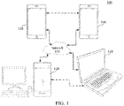
- FIG. 1 is a schematic diagram of an exemplary system architecture to which a technical solution according to an embodiment of this application is applicable.
- a system architecture 100 includes a plurality of terminal devices.
- the plurality of terminal devices may communicate with each other through, for example, a network 150.
- the system architecture 100 may include a first terminal device 110 and a second terminal device 120 that are interconnected by the network 150.
- the first terminal device 110 and the second terminal device 120 perform unidirectional data transmission.
- the first terminal device 110 may encode video data (for example, a video and picture stream acquired by the first terminal device 110) to transmit the encoded video data to the second terminal device 120 through the network 150.
- the encoded video data is transmitted in one or more encoded video bitstreams.
- the second terminal device 120 may receive the encoded video data from the network 150, decode the encoded video data to restore the video data, and display a video picture according to the restored video data.
- the system architecture 100 may include a third terminal device 130 and a fourth terminal device 140 that perform bidirectional transmission of the encoded video data.
- the bidirectional transmission may be performed, for example, during a video conference.
- each of the third terminal device 130 and the fourth terminal device 140 may encode video data (for example, the video and picture stream acquired by the terminal device) to transmit the encoded video data to an other terminal device of the third terminal device 130 and the fourth terminal device 140 through the network 150.
- Each of the third terminal device 130 and the fourth terminal device 140 may further receive the encoded video data transmitted by the other of the third terminal device 130 and the fourth terminal device 140, may decode the encoded video data to restore the video data, and may display a video picture on an accessible display apparatus according to the restored video data.
- the first terminal device 110, the second terminal device 120, the third terminal device 130, and the fourth terminal device 140 may be a server, a personal computer, and a smart phone, but the principles disclosed in this application may not be limited thereto. Embodiments disclosed in this application are applicable to a laptop computer, a tablet computer, a media player, and/or a dedicated video conference device.
- the network 150 represents any quantity of networks including, for example, a wired and/or wireless communication network that transmits the encoded video data between the first terminal device 110, the second terminal device 120, the third terminal device 130, and the fourth terminal device 140.
- a communication network 150 may exchange data in circuit-switched and/or packet-switched channels.
- the network may include a telecommunications network, a local area network, a wide area network, and/or the internet.
- a telecommunications network may include a local area network, a wide area network, and/or the internet.
- an architecture and a topology of network 150 may be immaterial to the operations disclosed in this application.
- FIG. 2 shows a placing manner of a video encoding apparatus and a video decoding apparatus in a streaming transmission environment.
- a topic disclosed in this application is equally applicable to other video-enabled applications including, for example, video conference and digital television (TV), and to storing compressed video on digital media including CD, DVD, memory stick, or the like.
- a streaming system may include an acquisition subsystem 213.
- the acquisition subsystem 213 may include a video source 201 such as a digital camera, and the video source creates an uncompressed video and picture stream 202.
- the video and picture stream 202 includes samples captured by a digital camera.
- the video and picture stream 202 is depicted as a thick line to emphasize the video and picture stream of a high data volume.
- the video and picture stream 202 may be processed by an electronic apparatus 220, and the electronic apparatus 220 includes a video encoding apparatus 203 coupled to a video source 201.
- the video encoding apparatus 203 may include hardware, software, or a combination of hardware and software to implement various aspects of the disclosed topic as described in detail below.
- the encoded video data 204 (or encoded video bitstream 204) is depicted as a thin line to emphasize the encoded video data 204 (or encoded video bitstream 204) of a lower data volume, which may be stored on a streaming transmission server 205 for future use.
- One or more streaming transmission client subsystems such as a client subsystem 206 and a client subsystem 208 in FIG. 2 , may access the streaming transmission server 205 to retrieve a copy 207 and a copy 209 of the encoded video data 204.
- the client subsystem 206 may include, for example, a video decoding apparatus 210 in the electronic apparatus 230.
- the video decoding apparatus 210 decodes the transmission copy 207 of the encoded video data and produces an output video and picture stream 211 that can be presented on a display 212 (for example, a display screen) or another presentation apparatus.
- encoded video data 204, video data 207, and video data 209 may be encoded according to specific video encoding/compression standards. Embodiments of these standards include ITU-T H.265.
- a video coding standard under development is informally referred to as versatile video coding (VVC), and this application may be used in the context of the VVC standard.
- VVC versatile video coding
- the electronic apparatus 220 and the electronic apparatus 230 may include other components not shown in the figure.
- the electronic apparatus 220 may include a video decoding apparatus
- the electronic apparatus 230 may further include a video encoding apparatus.
- HEVC High Efficiency Video Coding
- VVC Versatile Video Coding
- AVS Audio Video Coding Standard
- a video frame image is divided into several non-overlapping processing units according to a block size, and each processing unit performs a similar compression operation.
- the processing unit is referred to as a coding tree unit (CTU), or LCU.
- the CTU may continue to be further divided into finer divisions to obtain one or more basic coding units CU, and the CU is the most basic element in a coding link.
- Predictive coding includes intra-frame prediction and inter-frame prediction. After an original video signal is predicted by a selected reconstructed video signal, a residual video signal is obtained. An encoder side determines which predictive coding mode to select for the current CU and inform a decoder side.
- the intra-frame prediction refers to that a predicted signal comes from a region that has been encoded and reconstructed in the same image; and the inter-frame prediction refers to that a predicted signal comes from another image (referred to as a reference image) that has been encoded and is different from the current image.
- Transform & Quantization After a residual video signal undergoes transformation operations such as Discrete Fourier Transform (DFT) and DCT, a signal is transformed into a transformation domain, which is referred to as a transformation coefficient. A lossy quantization operation is further performed on the transformation coefficient, and a specific amount of information is lost, so that the quantized signal is beneficial to a compressed expression. In some video coding standards, there may be more than one transformation manner to be selected. Therefore, the encoder side also selects one of the transformation manners for the current CU and inform the decoder side. The degree of fineness of quantization is usually determined by the quantization parameter (QP).
- QP quantization parameter
- a larger value of the QP represents that coefficients within a greater range will be quantized as the same output, and therefore, may usually bring a greater distortion and lower bit rate; and conversely, a smaller value of the QP represents that coefficients within a smaller range will be quantized as a same output, and therefore, may usually bring a smaller distortion while corresponding to a higher bit rate.
- Entropy coding or statistical coding Statistical compression coding is performed quantized transform domain signals according to frequencies of occurrence of values, and finally, a binarized (0 or 1) compressed bitstream is outputted. In addition, other information is produced during the coding, such as the selected encoding mode and motion vector data, and the entropy coding also needs to be performed to reduce the bit rate.
- Calculation coding is a lossless coding manner that can effectively reduce the bit rate desired to express the same signal. Common calculation coding manners include variable length coding (VLC) or content adaptive binary arithmetic coding (CABAC).
- Loop filtering The transformed and quantized signal obtains a reconstructed image through operations such as inverse quantization, inverse transformation, and prediction compensation. Compared with an original image, the reconstructed image is different from the original image in some information due to the influence of quantization, that is, distortion is produced in the reconstructed image. Therefore, filtering operations can be performed on the reconstructed image, such as deblocking filter (DB), sample adaptive offset (SAO), or adaptive loop filter (ALF), which can effectively reduce the degree of distortion produced by quantization. Because these filtered reconstructed images are used as references for subsequent encoded images to predict future image signals, the filtering operation is also referred to as the loop filtering, that is, a filtering operation in an encoding loop.
- DB deblocking filter
- SAO sample adaptive offset
- ALF adaptive loop filter
- FIG. 3 is a basic flowchart of a video encoder, in which description is made by using the intra-frame prediction as an example.
- a difference operation is performed between the original image signal s k [ x, y ] and the predicted image signal ⁇ k [ x, y ] to obtain a residual signal u k [ x, y ] .
- Transform and quantization processing is performed on the residual signal u k [ x,y ] to obtain quantization coefficients.
- entropy coding is performed on the quantization coefficients to obtain the encoded bitstream (that is, the encoded video bitstream).
- inverse quantization and inverse transformation processing is performed on the quantization coefficients to obtain the reconstructed residual signal u' k [ x , y ] , and the predicted image signal ⁇ k [ x , y ] and the reconstructed residual signal u' k [ x , y ] are superimposed to generate an image signal s k * x y .
- the image signal s k * x y is inputted to an intra-frame mode decision-making module and an intra-frame prediction module for intra-frame prediction processing.
- a reconstructed image signal s' k [ x , y ] is outputted through the loop filtering, and the reconstructed image signal s ' k [ x , y ] may be used as a reference image of the next frame for motion estimation and motion compensation prediction. Then, a predicted image signal ⁇ k [ x , y ] of the next frame is obtained based on a result s ' r [ x + m x , y + m y ] of the motion compensation prediction and a result of the intra-frame prediction ⁇ s k * x y , and the foregoing process is repeated until the encoding is completed.
- the transformation mode used for the transformation of the residual signal (equivalent to the residual data corresponding to the subsequent encoding block) is determined according to the implicitly derived index value and the value of the index identifier included in the encoding block.
- the implicitly derived index value includes a correspondence with the calculation result of the quantization coefficients in the quantized coefficient block.
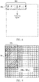
- non-zero coefficients of the residual signal in the quantized coefficient block after transform and quantization processing is performed has a high probability to be concentrated in the left and upper regions of the block, while the non-zero coefficients in the right and lower regions of the block are often 0, the SRCC technology is introduced.
- a size SRx ⁇ SRy of the upper left region of the non-zero coefficients included in each quantized coefficient block may be marked by the SRCC technology, where SRx is a horizontal coordinate of the rightmost non-zero coefficient in the quantized coefficient block, SRy is a vertical coordinate of the lowermost non-zero coefficient in the quantized coefficient block, and 1 ⁇ SRx ⁇ W, 1 ⁇ SRy ⁇ H, and coefficients outside the region are all 0.
- the SRCC technology determines the quantized coefficient region that is to be scanned in the quantized coefficient block by using (SRx, SRy). As shown in FIG. 4 , only the quantization coefficients in the scanning region marked by (SRx, SRy) are to be encoded.
- a scanning sequence of the encoding is shown in FIG. 5 , which can be a reverse zigzag scanning from a lower right corner to an upper left corner.
- entropy decoding is performed to obtain various mode information and quantization coefficients. Then, the inverse quantization and inverse transformation processing is performed on the quantization coefficients to obtain the residual signal.
- the predicted signal corresponding to the CU may be obtained. Then, the reconstructed signal may be obtained by adding the residual signal to the predicted signal. An operation such as the loop filtering is then performed on the reconstructed signal to generate a final output signal.
- the transformation processing performed on the residual signal causes energy of the residual signal to be concentrated on less low-frequency coefficients, that is, most coefficients have smaller values. Then, a subsequent quantization module converts the smaller coefficient value into a zero value, which greatly reduces the cost of encoding the residual signal.
- transformation kernels such as DST7 and DCT8 are introduced into the transformation processing process, and different transformation kernels can be used for horizontal transformation and vertical transformation on the residual signal.
- the possible transformation combinations that may be selected for performing transformation processing on a residual signal are as follows: (DCT2, DCT2), (DCT8, DCT8), (DCT8, DST7), (DST7, DCT8), and (DST7, DST7).
- the sub-block transform (SBT) technology is also mentioned in AVS3.
- SBT sub-block transform
- a width or a height of the non-zero residual sub-block is 64
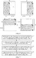
- the horizontal transformation and the vertical transformation of the non-zero residual sub-block are both DCT-2; and in other cases, the selection of the horizontal transformation and the vertical transformation is shown in FIG. 6 .
- FIG. 6 the selection of the horizontal transformation and the vertical transformation is shown in FIG. 6 .
- w1 in FIG. 6 may be 1/2 of the width (w), or may be 1/4 of w; and h1 may be 1/2 of the height (h), or may be 1/4 of h.
- some solutions propose to skip transform in a process of residual encoding in the gray part, and directly perform quantization and coefficient coding.
- rate-distortion optimization is to be used at the encoder side to make a decision.
- some residuals have weak correlations, and therefore, may skip the transformation process.
- a single DCT transformation kernel cannot adapt to all residual features, a plurality of DCT transformation kernels or DST transformation kernels may be selected as a transformation matrix combination for one residual block. In this case, although the adaptability of the transformation matrix combination to the residual block is improved, the encoding amount of a transformation mode index is increased, resulting in low encoding efficiency.
- the corresponding transformation mode is provided based on the implicitly derived index value and the explicit index identifier included in the encoding block.
- the encoding amount of the index identifier may be reduced based on indicating more transformation modes, which is beneficial to improve the video encoding efficiency.
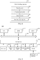
- FIG. 7 is a flowchart of a video decoding method according to an embodiment of this application.
- the video decoding method may be performed by a device with a computing processing function, such as a terminal device or a server.
- the video decoding method includes at least step S710 to step S740. A detailed description is as follows:
- Step S710 Perform entropy decoding processing on an encoding block of a video image frame to obtain a quantized coefficient block of residual data corresponding to the encoding block.
- the video image frame sequence includes a series of images, and each image may be further divided into slices.
- the slices may be divided into a series of LCUs (or CTUs), and the LCUs include several CUs.
- Each image may be referred to as a video image frame.
- the video image frame is encoded in blocks during encoding.
- macroblocks such as the H.264 standard.
- the macroblocks may be further divided into a plurality of prediction blocks that may be used for the predictive coding.
- coding unit CU In the HEVC standard, basic concepts such as a coding unit CU, a prediction unit (PU), and a transform unit (TU) are used, a plurality of block units are functionally divided, and a description is made in which a new tree-based structure is used.
- the CU may be divided into smaller CUs according to a quadtree, and the smaller CUs may be further divided to form a quadtree structure.
- the encoding block in this embodiment of this application may be the CU, or a block smaller than the CU, such as a smaller block obtained by dividing the CU.
- Step S720 Calculate quantization coefficients in the quantized coefficient block to obtain an implicitly derived index value.
- the quantization coefficients in the specified region in the quantized coefficient block may be calculated to obtain a calculation result of the quantization coefficients, and then the implicitly derived index value is determined according to parity of the calculation result.
- the implicitly derived index value is determined based on the parity of the calculation result. For example, if the calculation result is an odd number, the implicitly derived index value may be 1; and if the calculation result is an even number, the implicitly derived index value may be 0. Certainly, if the calculation result is an odd number, the implicitly derived index value may also be 0, and if the calculation result is an even number, the implicitly derived index value may be 1.
- the quantization coefficients in the specified region in the quantized coefficient block may be calculated to obtain a calculation result of the quantization coefficients, then a remainder of the calculation result for a set value is calculated, and then the implicitly derived index value is determined according to the remainder.
- the implicitly derived index value is determined for the remainder of the set value based on the calculation result.
- possible implicitly derived index values may be more than two, for example, the set value may be 3.
- a value of the remainder of the calculation result for 3 may be 0, 1, or 2, and each remainder corresponds to an implicitly derived index value.
- the remainder may be directly used as an implicitly derived index value.
- calculating the quantization coefficients in the specified region in the quantized coefficient block may include calculating a quantity of non-zero coefficients, even coefficients, non-zero even coefficients, or odd coefficients in the specified region in the quantized coefficient block, and using the quantity as the calculation result of the quantization coefficients.
- the specified region may be an entire region in the quantized coefficient block, may also be a partial region in the quantized coefficient block (such as one or more positions specified in the quantized coefficient block, at least one row specified in the quantized coefficient block, at least one column specified in the quantized coefficient block, at least one row specified in the quantized coefficient block, and a position on at least one oblique line in the quantized coefficient block), and may further be an SRCC region in the quantized coefficient block, such as an entire SRCC region or a part of the SRCC region.
- the part of the SRCC region may be one or more positions specified in the SRCC region, at least one row specified in the SRCC region, at least one column specified in the SRCC region, at least one row and at least one column specified in the SRCC region, and a position on at least one oblique line in the SRCC region,
- step S730 Determine a transformation mode of the encoding block according to the implicitly derived index value and a value of an index identifier included in the encoding block.
- the index identifier included in the encoding block is an explicit index identifier, and a value of the index identifier may be 1 or 0.
- One encoding block may include one or more index identifiers. That is, one encoding block may include one or more indication bits, and each indication bit is used for representing an index identifier.
- the implicitly derived index value and the value of the index identifier may be combined according to the set arrangement and combination manner to generate a combined index, and then, the transformation mode corresponding to the combined index is selected as the transformation mode of the encoding block according to the correspondence between the index value and the transformation mode.
- the set arrangement and combination manner may be either the explicit index before the implicitly derived index value, or the implicitly derived index value before the explicit index. That is, the combined index may be either a manner of "explicit index + implicitly derived index value” or a manner of "implicitly derived index value + explicit index”.
- the set arrangement and combination manner may be either the two explicit indices before the implicitly derived index value, or the implicitly derived index value before the two explicit indices, or the implicitly derived index value being between the two explicit indices. That is, the combined index may be either a manner of "explicit index 1 + explicit index 2 + implicitly derived index value", or a manner of "implicitly derived index value + explicit index 1 + explicit index 2", or a manner of "explicit index 1 + implicitly derived index value + explicit index 2".
- index identifiers may be combined with implicitly derived index values according to the set arrangement and combination manner.
- the correspondence between the index value and the transformation mode in the foregoing embodiment is preset according to the value of the combined index and the set transformation mode.
- the set transformation mode includes at least one of the following: a transformation matrix combination used for performing horizontal transformation and vertical transformation, an SBT mode, and a transform skip mode.
- a transformation kernel used for horizontal transformation and a transformation kernel used for vertical transformation in the transformation matrix combination may be selected from following transformation kernels: a DCT2 transformation kernel, a DCT5 transformation kernel, a DCT8 transformation kernel, a DST1 transformation kernel, and a DST7 transformation kernel.
- the transformation matrix combination may be: (DCT2, DCT2), (DCT8, DCT8), (DCT8, DST7), (DST7, DCT8), or (DST7, DST7).
- the first transformation kernel in the transformation matrix combination represents the transformation kernel used for performing the horizontal transformation
- the second transformation kernel represents the transformation kernel used for performing the vertical transformation.
- the transformation matrix combination (DCT8, DST7) represents that the horizontal transformation is performed by DCT8, and the vertical transformation is performed by DST7.
- Table 1 Explicit index Implicitly derived index value Transformation mode 1 0 (DST7, DST7) 1 (DCT8, DST7) 0 - (DCT2, DCT2)
- the set arrangement and combination manner is the explicit index before the implicitly derived index value.
- a case in which the explicit index is "0" and the implicitly derived index value is "-" represents that: when a value of the explicit index is 0, no matter what the implicitly derived index value is, the transformation mode is (DCT2, DCT2).
- the encoder side may perform implicit indication without adjusting the quantized coefficient block, and the decoder side does not need to perform a process of implicitly deriving the index (In addition, even if the encoder side adjusts the quantized coefficient block for implicit indication, the decoder side does not need to perform the process of implicitly deriving the index).
- Table 2 Explicit index Implicitly derived index value Transformation mode 0 - SBT 1 0 (DST7, DST7) 1 (DCT2, DCT2)
- a case in which the explicit index is "0" and the implicitly derived index value is "-" represents that: when a value of the explicit index is 0, no matter what the implicitly derived index value is, the transformation mode is SBT.
- the encoder side can perform implicit indication without adjusting the quantized coefficient block, and the decoder side does not need to perform a process of implicitly deriving the index (In addition, even if the encoder side adjusts the quantized coefficient block for implicit indication, the decoder side does not need to perform the process of implicitly deriving the index).
- Table 3 Explicit index Implicitly derived index value Transformation mode 0 - SBT 1 0 TS 1 (DCT2, DCT2)
- a case in which the explicit index is "0" and the implicitly derived index value is "-" represents that: when a value of the explicit index is 0, no matter what the implicitly derived index value is, the transformation mode is SBT.
- the encoder side can perform implicit indication without adjusting the quantized coefficient block, and the decoder side does not need to perform a process of implicitly deriving the index (In addition, even if the encoder side adjusts the quantized coefficient block for implicit indication, the decoder side does not need to perform the process of implicitly deriving the index).
- "TS” in Table 3 represents the transform skip mode, that is, the transformation process is skipped during encoding, and the inverse transformation process is to be skipped during decoding.
- the correspondence between the index value and the transformation mode in the foregoing embodiment may further be as shown in Table 4:
- the set arrangement and combination manner is the implicitly derived index value before the explicit index.
- a case in which the implicitly derived index value is "1" and the explicit index is "-" represents that: when the implicitly derived index value is 1, no matter what a value of the explicit index is, the transformation mode is (DCT2, DCT2).
- the encoder side does not need to encode the explicit index in the encoding block, and the decoder side does not need to perform the decoding process of the explicit index.
- Table 5 Explicit index 1 Explicit index 2 Implicitly derived index value Transformation mode 1 1 0 (DST7, DST7) 1 (DCT8, DST7) 0 - SBT 0 - - (DCT2, DCT2)
- the set arrangement and combination manner is two explicit indices before the implicitly derived index value.
- a case in which the explicit index 1 is "1", the explicit index 2 is "0", and the implicitly derived index value is "-" represents that: when a value of the explicit index 1 is 1, and a value of the explicit index 2 is "0", no matter what the implicitly derived index value is, the transformation mode is SBT.
- the encoder side can perform implicit indication without adjusting the quantized coefficient block, and the decoder side does not need to perform a process of implicitly deriving the index (In addition, even if the encoder side adjusts the quantized coefficient block for implicit indication, the decoder side does not need to perform the process of implicitly deriving the index).
- the decoder side does not need to perform the decoding process of the explicit index 2 (In addition, even if the encoder side adjusts the quantized coefficient block for implicit indication, the decoder side does not need to perform the process of implicitly deriving the index).
- the value of the explicit index 1, the value of the explicit index 2, the implicitly derived index value in Table 5, and the corresponding transformation modes are just examples. In other embodiments of this application, there may also be other manners, as shown in Table 6: Table 6 Explicit index 1 Explicit index 2 Implicitly derived index value Transformation mode 1 - - SBT 0 1 0 (DST7, DST7) 1 (DCT8, DST7) 0 - (DCT2, DCT2)
- the decoder side does not need to perform the decoding process of the explicit index 2 (In addition, even if the encoder side adjusts the quantized coefficient block for implicit indication, the decoder side does not need to perform the process of implicitly deriving the index).
- the correspondence between the index value and the transformation mode in the foregoing embodiment may further be as shown in Table 7: Table 7 Explicit index 1 Implicitly derived index value Explicit index 2 Transformation mode 1 0 - (DST7, DST7) 1 0 (DCT8, DST7) 1 (DST7, DCT8) 0 - - (DCT2, DCT2)
- the set arrangement and combination manner is the implicitly derived index value being between two explicit indices.
- a case in which the explicit index 1 is "1", the implicitly derived index value is "0", and the explicit index 2 is "-" represents that: when a value of the explicit index 1 is 1, and the implicitly derived index value is 0, no matter what a value of the explicit index 2 is, the transformation mode is (DST7, DST7).
- the encoder side does not need to encode the explicit index 2 in the encoding block, and the decoder side does not need to perform the decoding process of the explicit index 2.
- the decoder side does not need to perform the decoding process of the explicit index 2 (In addition, even if the encoder side adjusts the quantized coefficient block for implicit indication, the decoder side does not need to perform the process of implicitly deriving the index).
- a manner of determining for the encoding block whether the transformation mode corresponding to the encoding block is to be jointly determined according to the implicitly derived index value and the index identifier included in the encoding block may include at least one of the following: an index identifier included in a sequence header of encoded data corresponding to a video image frame sequence, an index identifier included in an image header of encoded data corresponding to a video image frame, and a size of the encoding block.
- a value of the index identifier included in the sequence header is used for indicating, for all encoding blocks, or encoding blocks in an intra-frame encoding mode, or encoding blocks in an inter-frame encoding mode in the encoded data corresponding to the video image frame sequence, whether the transformation mode corresponding to the encoding block is to be jointly determined according to the implicitly derived index value and the index identifier included in the encoding block.
- the index identifier included in the sequence header either indicates for all encoding blocks in the encoded data corresponding to the video image frame sequence, the transformation mode corresponding to the encoding block is to be jointly determined according to the implicitly derived index value and the explicit index, or indicates for the encoding block in the intra-frame encoding mode in the encoded data corresponding to the video image frame sequence, the transformation mode corresponding to the encoding block is to be jointly determined according to the implicitly derived index value and the explicit index, or indicates for the encoding block in the inter-frame encoding mode in the encoded data corresponding to the video image frame sequence, the transformation mode corresponding to the encoding block is to be jointly determined according to the implicitly derived index value and the explicit index.
- the sequence header includes two index identifiers, the first index identifier and the second index identifier respectively, where a value of the first index identifier and a value of the second index identifier are respectively used for indicating for encoding blocks in an intra-frame encoding mode and encoding blocks in an inter-frame encoding mode in the encoded data corresponding to the video image frame sequence, whether the transformation mode corresponding to the encoding block is to be jointly determined according to the implicitly derived index value and the explicit index.
- the sequence header includes index identifiers respectively corresponding to the encoding block in the intra-frame encoding mode and the encoding block in the inter-frame encoding mode, to respectively indicate for the two types of encoding blocks whether the transformation mode corresponding to the encoding block is to be jointly determined according to the implicitly derived index value and the explicit index.
- a specific indication manner may be:
- the size of a specific encoding block in the encoded data corresponding to the video image frame sequence being less than the set value indicates that the transformation mode corresponding to the encoding block is to be jointly determined according to the implicitly derived index value and the index identifier included in the encoding block.
- the size of a specific encoding block in the encoded data corresponding to the video image frame sequence being larger than the set value indicates that the transformation mode corresponding to the encoding block is not to be jointly determined according to the implicitly derived index value and the index identifier included in the encoding block.
- the index identifier in the sequence header of the encoded data corresponding to the video image frame sequence is 0 (the value is only an example), it indicates that for all the encoding blocks in the encoded data corresponding to the video image frame sequence, the transformation mode corresponding to the encoding block is not to be jointly determined according to the implicitly derived index value and the index identifier included in the encoding block.
- step S740 Perform inverse transformation processing on the inverse quantization result of the quantized coefficient block based on the transformation mode corresponding to the encoding block.
- the process reference may be made to the related descriptions in the foregoing embodiments, and details are not repeated herein.
- the corresponding transformation mode may be indicated based on the implicitly derived index value and the explicit index identifier included in the encoding block. In this way, the encoding amount of the index identifier may be reduced while indicating more transformation modes, which is beneficial to improve the video encoding efficiency.
- FIG. 8 is a block diagram of a video decoding apparatus according to an embodiment of this application.
- the video decoding apparatus may be arranged in a device with a computing processing function, such as a terminal device or a server.
- the video decoding apparatus 800 includes: a decoding unit 802, a first processing unit 804, a selection unit 806, and a second processing unit 808.
- a decoding unit 802 is configured to perform entropy decoding processing on an encoding block of a video image frame to obtain a quantized coefficient block of residual data corresponding to the encoding block; a first processing unit 804 is configured to calculate quantization coefficients in the quantized coefficient block to obtain an implicitly derived index value; a selection unit 806 is configured to determine a transformation mode of the encoding block according to the implicitly derived index value and a value of an index identifier included in the encoding block; and a second processing unit 808 is configured to perform inverse transformation processing on an inverse quantization result of the quantized coefficient block based on the transformation mode of the encoding block.
- the video decoding apparatus 800 further includes: a determining unit, configured to determine for the encoding block, whether the transformation mode corresponding to the encoding block is to be jointly determined according to the implicitly derived index value and the index identifier comprised in the encoding block; and if yes, trigger the selection unit to perform a step of determining a transformation mode of the encoding block according to the implicitly derived index value and a value of an index identifier included in the encoding block.
- a determining unit configured to determine for the encoding block, whether the transformation mode corresponding to the encoding block is to be jointly determined according to the implicitly derived index value and the index identifier comprised in the encoding block.
- a manner in which the determining unit determines for the encoding block, whether the transformation mode corresponding to the encoding block is to be jointly determined according to the implicitly derived index value and the index identifier comprised in the encoding block includes at least one of the following: an index identifier included in a sequence header of encoded data corresponding to a video image frame sequence, an index identifier included in an image header of encoded data corresponding to a video image frame, and a size of the encoding block.
- a value of the index identifier included in the sequence header is used for indicating for all encoding blocks, or encoding blocks in an intra-frame encoding mode, or encoding blocks in an inter-frame encoding mode in the encoded data corresponding to the video image frame sequence, whether the transformation mode corresponding to the encoding block is to be jointly determined according to the implicitly derived index value and the index identifier included in the encoding block.
- a value of a first index identifier and a value of a second index identifier included in the sequence header are respectively used for indicating for encoding blocks in an intra-frame encoding mode and encoding blocks in an inter-frame encoding mode in the encoded data corresponding to the video image frame sequence, whether the transformation mode corresponding to the encoding block is to be jointly determined according to the implicitly derived index value and the index identifier included in the encoding block.
- the first processing unit 804 is configured to: calculate quantization coefficients in a specified region in the quantized coefficient block to obtain a calculation result of the quantization coefficients; and determine the implicitly derived index value according to parity of the calculation result.
- the first processing unit 804 is configured to: calculate quantization coefficients in a specified region in the quantized coefficient block to obtain a calculation result of the quantization coefficients; and calculate a remainder of the calculation result for a set value; and determine the implicitly derived index value according to the remainder.
- the first processing unit 804 is configured to calculate a quantity of non-zero coefficients, even coefficients, non-zero even coefficients, or odd coefficients in the specified region in the quantized coefficient block, and use the quantity as the calculation result of the quantization coefficients.
- the specified region includes an entire region in the quantized coefficient block or an SRCC region in the quantized coefficient block.
- the selection unit 806 is configured to: combine the implicitly derived index value and the value of the index identifier according to a set arrangement and combination manner to generate a combined index; and select a transformation mode corresponding to the combined index as a transformation mode of the encoding block according to a correspondence between an index value and a transformation mode.
- the correspondence between the index value and the transformation mode is preset according to a value of the combined index and a set transformation mode.
- the set transformation mode includes at least one of the following: a transformation matrix combination used for performing horizontal transformation and vertical transformation, a sub-block transformation (SBT) mode, and a transform skip mode.
- a transformation kernel used for horizontal transformation and a transformation kernel used for vertical transformation in the transformation matrix combination are selected from following transformation kernels: a DCT2 transformation kernel, a DCT5 transformation kernel, a DCT8 transformation kernel, a DST1 transformation kernel, and a DST7 transformation kernel.
- the encoding block includes at least one of the index identifiers.
- FIG. 9 is a schematic structural diagram of a computer system adapted to implement an electronic device according to an embodiment of this application.
- a computer system 900 of the electronic device shown in FIG. 9 is merely an example, and does not constitute any limitation on functions and use ranges of the embodiments of this application.
- the computer system 900 includes a central processing unit (CPU) 901, which may perform various suitable actions and processing based on a program stored in a read-only memory (ROM) 902 or a program loaded from a storage part 908 into a random access memory (RAM) 903, for example, perform the method described in the foregoing embodiments.
- the RAM 903 further stores various programs and data required for system operations.
- the CPU 901, the ROM 902, and the RAM 903 are connected to each other by using a bus 904.
- An input/output (I/O) interface 905 is also connected to the bus 904.
- the following components are connected to the I/O interface 905: an input part 906 including a keyboard, a mouse, or the like; an output part 907 including a cathode ray tube (CRT), a liquid crystal display (LCD), a speaker, or the like; a storage part 908 including a hard disk, or the like; and a communication part 909 including a network interface card such as a local area network (LAN) card or a modem.
- the communication part 909 performs communication processing through a network such as the Internet.
- a driver 910 is also connected to the I/O interface 905 as required.
- a removable medium 911 such as a magnetic disk, an optical disc, a magneto-optical disk, or a semiconductor memory, is installed on the drive 910 as required, so that a computer program read from the removable medium is installed into the storage part 908 as required.
- an embodiment of this application includes a computer program product.
- the computer program product includes a computer program stored in a computer-readable medium.
- the computer program includes a computer program used for performing a method shown in the flowchart.
- the computer program may be downloaded and installed from a network through the communication part 909, and/or installed from the removable medium 911.
- the various functions defined in the system of this application are executed.
- the computer-readable medium shown in the embodiments of this application may be a computer-readable signal medium or a computer-readable storage medium or any combination thereof.
- the computer-readable storage medium may be, for example, but is not limited to, an electric, magnetic, optical, electromagnetic, infrared, or semi-conductive system, apparatus, or component, or any combination thereof.
- a more specific example of the computer-readable storage medium may include but is not limited to: an electrical connection having one or more wires, a portable computer magnetic disk, a hard disk, a random access memory (RAM), a read-only memory (ROM), an erasable programmable read-only memory (EPROM), a flash memory, an optical fiber, a compact disc read-only memory (CD-ROM), an optical storage device, a magnetic storage device, or any appropriate combination thereof.
- the computer-readable storage medium may be any tangible medium containing or storing a program, and the program may be used by or used in combination with an instruction execution system, apparatus, or device.
- the computer-readable signal medium may include a data signal transmitted in a baseband or as part of a carrier, and stores a computer-readable computer program.
- the data signal propagated in such a way may assume a plurality of forms, including, but not limited to, an electromagnetic signal, an optical signal, or any appropriate combination thereof.
- the computer-readable signal medium may be further any computer-readable medium in addition to a computer-readable storage medium.
- the computer-readable medium may transmit, propagate, or transmit a program that is used by or used in combination with an instruction execution system, apparatus, or device.
- the computer program included in the computer-readable medium may be transmitted by using any suitable medium, including but not limited to: a wireless medium, a wire, or the like, or any suitable combination thereof.
- Each box in a flowchart or a block diagram may represent a module, a program segment, or a part of code.
- the module, the program segment, or the part of code includes one or more executable instructions used for implementing specified logic functions.
- functions annotated in boxes may alternatively occur in a sequence different from that annotated in an accompanying drawing. For example, actually two boxes shown in succession may be performed basically in parallel, and sometimes the two boxes may be performed in a reverse sequence. This is determined by a related function.
- Each box in a block diagram and/or a flowchart and a combination of boxes in the block diagram and/or the flowchart may be implemented by using a dedicated hardware-based system configured to perform a specified function or operation, or may be implemented by using a combination of dedicated hardware and a computer instruction.
- this application further provides a computer-readable medium.
- the computer-readable medium may be included in the electronic device described in the foregoing embodiments, or may exist alone and is not disposed in the electronic device.
- the computer-readable medium carries one or more programs, the one or more programs, when executed by the electronic device, causing the electronic device to implement the method described in the foregoing embodiments.
- the exemplary implementations described herein may be implemented by using software, or may be implemented by combining software and necessary hardware. Therefore, the technical solutions of the implementations of this application may be implemented in a form of a software product.
- the software product may be stored in a non-volatile storage medium (which may be a CD-ROM, a USB flash drive, a removable hard disk, or the like) or on a network, including several instructions for instructing a computing device (which may be a personal computer, a server, a touch terminal, a network device, or the like) to perform the methods according to the implementations of this application.
Abstract
Description
- This application claims priority to
Chinese Patent Application No. 202011112822.0, entitled "VIDEO DECODING METHOD AND APPARATUS, COMPUTER-READABLE MEDIUM, AND ELECTRONIC DEVICE" and filed with the China National Intellectual Property Administration on October 16, 2020 - This application relates to the field of computers and communication technologies, and specifically, to video encoding and decoding.
- In a video encoding process, an encoder side usually performs transformation, quantization, and entropy coding processing on residual data between original video data and predicted video data before transmitting the residual data to a decoder side. There are also some residuals with weak correlation, which may skip a transformation process.
- Due to the diversity of the residual data, a single discrete cosine transform (DCT) transformation kernel cannot adapt to all residual features. Therefore, for a residual block, a plurality of DCT transformation kernels or discrete sine transform (DST) transformation kernels may be selected as transformation matrix combinations.
- In this case, although the adaptability of the transformation matrix combinations to the residual block is improved, the encoding amount of a transformation mode index is increased, resulting in relatively low encoding efficiency.
- Embodiments of this application provide a video decoding method and apparatus, a computer-readable medium, and an electronic device, which can effectively improve video encoding efficiency at least to a certain extent.
- Other features and advantages of this application become obvious through the following detailed descriptions, or may be partially learned through the practice of this application.
- According to an aspect of this embodiment of this application, a video decoding method is provided. The method is performed by a device with a computing processing function, and the method includes: performing entropy decoding processing on an encoding block of a video image frame to obtain a quantized coefficient block of residual data corresponding to the encoding block; calculating quantization coefficients in the quantized coefficient block to obtain an implicitly derived index value; determining a transformation mode of the encoding block according to the implicitly derived index value and a value of an index identifier included in the encoding block; and performing inverse transformation processing on an inverse quantization result of the quantized coefficient block based on the transformation mode of the encoding block.
- According to an aspect of this embodiment of this application, a video encoding method is provided. The method is performed by a device with a computing processing function, and the method includes: performing a difference operation on an original image signal and a predicted image signal corresponding to an encoding block to obtain residual data corresponding to the encoding block; performing transform and quantization processing on the residual data according to a transformation mode corresponding to the encoding block to obtain a quantized coefficient block of the residual data corresponding to the encoding block, where the transformation mode corresponding to the encoding block is determined according to an implicitly derived index value and a value of an index identifier included in the encoding block, and the implicitly derived index value has a correspondence with a calculation result of quantization coefficients in the quantized coefficient block; and performing entropy coding on the quantization coefficients in the quantized coefficient block to obtain an encoded video bitstream.
- According to an aspect of this embodiment of this application, a video decoding apparatus is provided. The apparatus is arranged in a device with a computing processing function, and the apparatus includes: a decoding unit, configured to perform entropy decoding processing on an encoding block of a video image frame to obtain a quantized coefficient block of residual data corresponding to the encoding block; a first processing unit, configured to calculate quantization coefficients in the quantized coefficient block to obtain an implicitly derived index value; a selection unit, configured to determine a transformation mode of the encoding block according to the implicitly derived index value and a value of an index identifier included in the encoding block; and a second processing unit, configured to perform inverse transformation processing on an inverse quantization result of the quantized coefficient block based on the transformation mode of the encoding block.
- In some embodiments of this application, based on the foregoing solution, the video decoding apparatus further includes: a determining unit, configured to determine, for the encoding block, whether the transformation mode corresponding to the encoding block is to be jointly determined according to the implicitly derived index value and the index identifier included in the encoding block; and
- in response to determining that the transformation mode corresponding to the encoding block is to be jointly determined, trigger the selection unit to perform a step of determining a transformation mode of the encoding block according to the implicitly derived index value and a value of an index identifier included in the encoding block.
- In some embodiments of this application, based on the foregoing solution, a manner in which the determining unit determines for the encoding block, whether the transformation mode corresponding to the encoding block is to be jointly determined according to the implicitly derived index value and the index identifier included in the encoding block includes at least one of the following: an index identifier included in a sequence header of encoded data corresponding to a video image frame sequence, an index identifier included in an image header of encoded data corresponding to a video image frame, and a size of the encoding block.
- In some embodiments of this application, based on the foregoing solution, a value of the index identifier included in the sequence header is used for indicating whether all encoding blocks, or encoding blocks in an intra-frame encoding mode, or encoding blocks in an inter-frame encoding mode in the encoded data corresponding to the video image frame sequence is to jointly determine the transformation mode corresponding to the encoding block according to the implicitly derived index value and the index identifier included in the encoding block.
- In some embodiments of this application, based on the foregoing solution, a value of a first index identifier and a value of a second index identifier included in the sequence header are respectively used for indicating for encoding blocks in an intra-frame encoding mode and encoding blocks in an inter-frame encoding mode in the encoded data corresponding to the video image frame sequence, whether the transformation mode corresponding to the encoding block is to be jointly determined according to the implicitly derived index value and the index identifier included in the encoding block.
- In some embodiments of this application, based on the foregoing solution, the first processing unit is configured to: calculate quantization coefficients in a specified region in the quantized coefficient block to obtain a calculation result of the quantization coefficients; and determine the implicitly derived index value according to parity of the calculation result.
- In some embodiments of this application, based on the foregoing solution, the first processing unit is configured to: calculate quantization coefficients in a specified region in the quantized coefficient block to obtain a calculation result of the quantization coefficients; calculate a remainder of the calculation result for a set value; and determine the implicitly derived index value according to the remainder.
- In some embodiments of this application, based on the foregoing solution, the first processing unit is configured to calculate a quantity of non-zero coefficients, even coefficients, non-zero even coefficients, or odd coefficients in the specified region in the quantized coefficient block, and use the quantity as the calculation result of the quantization coefficients.
- In some embodiments of this application, based on the foregoing solution, the specified region includes an entire region in the quantized coefficient block or a scan region coefficient coding (SRCC) region in the quantized coefficient block.
- In some embodiments of this application, based on the foregoing solution, the selection unit is configured to: combine the implicitly derived index value and the value of the index identifier according to a set arrangement and combination manner to generate a combined index; and select a transformation mode corresponding to the combined index as a transformation mode of the encoding block according to a correspondence between an index value and a transformation mode.
- In some embodiments of this application, based on the foregoing solution, the correspondence between the index value and the transformation mode is preset according to a value of the combined index and a set transformation mode.
- In some embodiments of this application, based on the foregoing solution, the set transformation mode includes at least one of the following: a transformation matrix combination used for performing horizontal transformation and vertical transformation, a sub-block transformation (SBT) mode, and a transform skip mode.
- In some embodiments of this application, based on the foregoing solution, a transformation kernel used for horizontal transformation and a transformation kernel used for vertical transformation in the transformation matrix combination are selected from following transformation kernels: a DCT2 transformation kernel, a DCT5 transformation kernel, a DCT8 transformation kernel, a DST1 transformation kernel, and a DST7 transformation kernel.
- In some embodiments of this application, based on the foregoing solution, the encoding block includes at least one of the index identifiers.
- According to an aspect of this embodiment of this application, a video encoding apparatus is provided. The apparatus is arranged in a device with a computing processing function, and the apparatus includes: a first processing unit, configured to perform a difference operation on an original image signal and a predicted image signal corresponding to an encoding block to obtain residual data corresponding to the encoding block; a second processing unit, configured to perform transform and quantization processing on the residual data according to a transformation mode corresponding to the encoding block to obtain a quantized coefficient block of residual data corresponding to the encoding block, where the transformation mode corresponding to the encoding block is determined according to an implicitly derived index value and a value of an index identifier included in the encoding block, and the implicitly derived index value has a correspondence with a calculation result of quantization coefficients in the quantized coefficient block; and an encoding unit, configured to perform entropy coding on the quantization coefficients in the quantized coefficient block to obtain an encoded video bitstream.
- According to an aspect of the embodiments of this application, a computer-readable medium is provided, storing a computer program, the computer program, when executed by a processor, implementing the video decoding method or the video encoding method according to the foregoing embodiments.
- According to an aspect of this embodiment of this application, an electronic device is provided, including: one or more processors; and a storage apparatus, configured to store one or more programs, the one or more programs, when executed by the one or more processors, causing the one or more processors to implement the video decoding method or the video encoding method according to the foregoing embodiments.
- According to an aspect of this embodiment of this application, a computer program product or a computer program is provided, the computer program product or the computer program including computer instructions, the computer instructions being stored in a computer-readable storage medium. A processor of a computer device reads the computer instructions from the computer-readable storage medium and executes the computer instructions to cause the computer device to implement the video decoding method or the video encoding method according to the foregoing embodiments.
- In the technical solutions provided in some embodiments of this application, the quantization coefficients in the quantized coefficient block are calculated to obtain the implicitly derived index value. The transformation mode of the encoding block is determined according to the implicitly derived index value and the value of the index identifier included in the encoding block. The index identifier included in the encoding block is an explicit index identifier, so that the corresponding transformation mode can be indicated based on the implicitly derived index value and the explicit index identifier included in the encoding block. In this way, the encoding amount of the index identifier may be reduced while indicating more transformation modes, which is beneficial to improve the video encoding efficiency.
- It is to be understood that the foregoing general descriptions and the following detailed descriptions are merely for illustration and explanation purposes and are not intended to limit this application.
- Accompanying drawings herein are incorporated into a specification and constitute a part of this specification, show embodiments that conform to this application, and are used for describing a principle of this application together with this specification. Obviously, the accompanying drawings in the following descriptions are merely some embodiments of this application, and a person of ordinary skill in the art may further obtain other accompanying drawings according to the accompanying drawings without creative efforts. In the accompanying drawings:
-
FIG. 1 is a schematic diagram of an exemplary system architecture to which a technical solution according to an embodiment of this application is applicable. -
FIG. 2 is a schematic diagram of a placing manner of a video encoding apparatus and a video decoding apparatus in a streaming transmission system. -
FIG. 3 is a basic flowchart of a video encoder. -
FIG. 4 is a scanning region marked by an SRCC technology. -
FIG. 5 is a schematic diagram of a sequence of scanning the marked scanning region. -
FIG. 6 is a schematic diagram of a transformation combination in the sub-block transformation technology. -
FIG. 7 is a flowchart of a video decoding method according to an embodiment of this application. -
FIG. 8 is a block diagram of a video decoding apparatus according to an embodiment of this application. -
FIG. 9 is a schematic structural diagram of a computer system adapted to implement an electronic device according to an embodiment of this application. - Exemplary implementations are now described more comprehensively with reference to the accompanying drawings. However, the exemplary implementations can be implemented in various forms and are not construed as being limited to the examples herein. Conversely, such implementations are provided to make this application more comprehensive and complete, and fully convey the concepts of the exemplary implementations to a person skilled in the art.
- In addition, the described features, structures or characteristics may be combined in one or more embodiments in any appropriate manner. In the following descriptions, a lot of specific details are provided to give a comprehensive understanding of the embodiments of this application. However, a person skilled in the art is to be aware that, the technical solutions in this application may be implemented without one or more of the particular details, or another method, unit, apparatus, or step may be used. In other cases, well-known methods, apparatuses, implementations, or operations are not shown or described in detail, to avoid obscuring the aspects of this application.
- The block diagrams shown in the accompanying drawings are merely functional entities and do not necessarily correspond to physically independent entities. That is, the functional entities may be implemented in a software form, or in one or more hardware modules or integrated circuits, or in different networks and/or processor apparatuses and/or microcontroller apparatuses.
- The flowcharts shown in the accompanying drawings are merely examples for descriptions, do not need to include all content and operations/steps, and do not need to be performed in the described orders either. For example, some operations/steps may be further divided, while some operations/steps may be combined or partially combined. Therefore, an actual execution order may change according to an actual case.
- "Plurality of' mentioned in the specification means two or more. "And/or" describes an association relationship for describing associated objects and represents that three relationships may exist. For example, A and/or B may represent the following three cases: only A exists, both A and B exist, and only B exists. The character "/" generally indicates an "or" relationship between the associated objects.
-
FIG. 1 is a schematic diagram of an exemplary system architecture to which a technical solution according to an embodiment of this application is applicable. - As shown in
FIG. 1 , asystem architecture 100 includes a plurality of terminal devices. The plurality of terminal devices may communicate with each other through, for example, anetwork 150. For example, thesystem architecture 100 may include a firstterminal device 110 and a secondterminal device 120 that are interconnected by thenetwork 150. In the embodiment inFIG. 1 , the firstterminal device 110 and the secondterminal device 120 perform unidirectional data transmission. - For example, the first
terminal device 110 may encode video data (for example, a video and picture stream acquired by the first terminal device 110) to transmit the encoded video data to the secondterminal device 120 through thenetwork 150. The encoded video data is transmitted in one or more encoded video bitstreams. The secondterminal device 120 may receive the encoded video data from thenetwork 150, decode the encoded video data to restore the video data, and display a video picture according to the restored video data. - In an embodiment of this application, the
system architecture 100 may include a thirdterminal device 130 and a fourthterminal device 140 that perform bidirectional transmission of the encoded video data. The bidirectional transmission may be performed, for example, during a video conference. For the bidirectional data transmission, each of the thirdterminal device 130 and the fourthterminal device 140 may encode video data (for example, the video and picture stream acquired by the terminal device) to transmit the encoded video data to an other terminal device of the thirdterminal device 130 and the fourthterminal device 140 through thenetwork 150. Each of the thirdterminal device 130 and the fourthterminal device 140 may further receive the encoded video data transmitted by the other of the thirdterminal device 130 and the fourthterminal device 140, may decode the encoded video data to restore the video data, and may display a video picture on an accessible display apparatus according to the restored video data. - In the embodiment in
FIG. 1 , the firstterminal device 110, the secondterminal device 120, the thirdterminal device 130, and the fourthterminal device 140 may be a server, a personal computer, and a smart phone, but the principles disclosed in this application may not be limited thereto. Embodiments disclosed in this application are applicable to a laptop computer, a tablet computer, a media player, and/or a dedicated video conference device. Thenetwork 150 represents any quantity of networks including, for example, a wired and/or wireless communication network that transmits the encoded video data between the firstterminal device 110, the secondterminal device 120, the thirdterminal device 130, and the fourthterminal device 140. Acommunication network 150 may exchange data in circuit-switched and/or packet-switched channels. The network may include a telecommunications network, a local area network, a wide area network, and/or the internet. For the objective of this application, unless explained below, an architecture and a topology ofnetwork 150 may be immaterial to the operations disclosed in this application. - In an embodiment of this application,
FIG. 2 shows a placing manner of a video encoding apparatus and a video decoding apparatus in a streaming transmission environment. A topic disclosed in this application is equally applicable to other video-enabled applications including, for example, video conference and digital television (TV), and to storing compressed video on digital media including CD, DVD, memory stick, or the like. - A streaming system may include an
acquisition subsystem 213. Theacquisition subsystem 213 may include avideo source 201 such as a digital camera, and the video source creates an uncompressed video andpicture stream 202. In an embodiment, the video andpicture stream 202 includes samples captured by a digital camera. Compared with the encoded video data 204 (or the encoded video bitstream 204), the video andpicture stream 202 is depicted as a thick line to emphasize the video and picture stream of a high data volume. The video andpicture stream 202 may be processed by anelectronic apparatus 220, and theelectronic apparatus 220 includes avideo encoding apparatus 203 coupled to avideo source 201. Thevideo encoding apparatus 203 may include hardware, software, or a combination of hardware and software to implement various aspects of the disclosed topic as described in detail below. Compared with the video andpicture stream 202, the encoded video data 204 (or encoded video bitstream 204) is depicted as a thin line to emphasize the encoded video data 204 (or encoded video bitstream 204) of a lower data volume, which may be stored on astreaming transmission server 205 for future use. One or more streaming transmission client subsystems, such as aclient subsystem 206 and aclient subsystem 208 inFIG. 2 , may access thestreaming transmission server 205 to retrieve acopy 207 and acopy 209 of the encodedvideo data 204. Theclient subsystem 206 may include, for example, avideo decoding apparatus 210 in theelectronic apparatus 230. Thevideo decoding apparatus 210 decodes thetransmission copy 207 of the encoded video data and produces an output video andpicture stream 211 that can be presented on a display 212 (for example, a display screen) or another presentation apparatus. In some streaming transmission systems, encodedvideo data 204,video data 207, and video data 209 (for example, video bitstreams) may be encoded according to specific video encoding/compression standards. Embodiments of these standards include ITU-T H.265. In an embodiment, a video coding standard under development is informally referred to as versatile video coding (VVC), and this application may be used in the context of the VVC standard. - The
electronic apparatus 220 and theelectronic apparatus 230 may include other components not shown in the figure. For example, theelectronic apparatus 220 may include a video decoding apparatus, and theelectronic apparatus 230 may further include a video encoding apparatus. - In an embodiment of this application, using the international video coding standard High Efficiency Video Coding (HEVC), Versatile Video Coding (VVC), and the China national video coding standard Audio Video Coding Standard (AVS) as an example, after a video frame image is inputted, a video frame image is divided into several non-overlapping processing units according to a block size, and each processing unit performs a similar compression operation. The processing unit is referred to as a coding tree unit (CTU), or LCU. The CTU may continue to be further divided into finer divisions to obtain one or more basic coding units CU, and the CU is the most basic element in a coding link. The following introduces some concepts when the CU is encoded:
- Predictive coding: Predictive coding includes intra-frame prediction and inter-frame prediction. After an original video signal is predicted by a selected reconstructed video signal, a residual video signal is obtained. An encoder side determines which predictive coding mode to select for the current CU and inform a decoder side. The intra-frame prediction refers to that a predicted signal comes from a region that has been encoded and reconstructed in the same image; and the inter-frame prediction refers to that a predicted signal comes from another image (referred to as a reference image) that has been encoded and is different from the current image.
- Transform & Quantization: After a residual video signal undergoes transformation operations such as Discrete Fourier Transform (DFT) and DCT, a signal is transformed into a transformation domain, which is referred to as a transformation coefficient. A lossy quantization operation is further performed on the transformation coefficient, and a specific amount of information is lost, so that the quantized signal is beneficial to a compressed expression. In some video coding standards, there may be more than one transformation manner to be selected. Therefore, the encoder side also selects one of the transformation manners for the current CU and inform the decoder side. The degree of fineness of quantization is usually determined by the quantization parameter (QP). A larger value of the QP represents that coefficients within a greater range will be quantized as the same output, and therefore, may usually bring a greater distortion and lower bit rate; and conversely, a smaller value of the QP represents that coefficients within a smaller range will be quantized as a same output, and therefore, may usually bring a smaller distortion while corresponding to a higher bit rate.
- Entropy coding or statistical coding: Statistical compression coding is performed quantized transform domain signals according to frequencies of occurrence of values, and finally, a binarized (0 or 1) compressed bitstream is outputted. In addition, other information is produced during the coding, such as the selected encoding mode and motion vector data, and the entropy coding also needs to be performed to reduce the bit rate. Calculation coding is a lossless coding manner that can effectively reduce the bit rate desired to express the same signal. Common calculation coding manners include variable length coding (VLC) or content adaptive binary arithmetic coding (CABAC).
- Loop filtering: The transformed and quantized signal obtains a reconstructed image through operations such as inverse quantization, inverse transformation, and prediction compensation. Compared with an original image, the reconstructed image is different from the original image in some information due to the influence of quantization, that is, distortion is produced in the reconstructed image. Therefore, filtering operations can be performed on the reconstructed image, such as deblocking filter (DB), sample adaptive offset (SAO), or adaptive loop filter (ALF), which can effectively reduce the degree of distortion produced by quantization. Because these filtered reconstructed images are used as references for subsequent encoded images to predict future image signals, the filtering operation is also referred to as the loop filtering, that is, a filtering operation in an encoding loop.
- In an embodiment of this application,
FIG. 3 is a basic flowchart of a video encoder, in which description is made by using the intra-frame prediction as an example. A difference operation is performed between the original image signal sk [x, y] and the predicted image signal ŝk [x, y] to obtain a residual signal uk [x, y] . Transform and quantization processing is performed on the residual signal uk [x,y] to obtain quantization coefficients. On the one hand, entropy coding is performed on the quantization coefficients to obtain the encoded bitstream (that is, the encoded video bitstream). On the other hand, inverse quantization and inverse transformation processing is performed on the quantization coefficients to obtain the reconstructed residual signal u'k [x, y] , and the predicted image signal ŝk [x, y] and the reconstructed residual signal u'k [x,y] are superimposed to generate an image signal


- The transformation mode used for the transformation of the residual signal (equivalent to the residual data corresponding to the subsequent encoding block) is determined according to the implicitly derived index value and the value of the index identifier included in the encoding block. The implicitly derived index value includes a correspondence with the calculation result of the quantization coefficients in the quantized coefficient block.
- In addition, because non-zero coefficients of the residual signal in the quantized coefficient block after transform and quantization processing is performed has a high probability to be concentrated in the left and upper regions of the block, while the non-zero coefficients in the right and lower regions of the block are often 0, the SRCC technology is introduced. A size SRx × SRy of the upper left region of the non-zero coefficients included in each quantized coefficient block (the size is W × H) may be marked by the SRCC technology, where SRx is a horizontal coordinate of the rightmost non-zero coefficient in the quantized coefficient block, SRy is a vertical coordinate of the lowermost non-zero coefficient in the quantized coefficient block, and 1≤SRx≤W, 1≤SRy≤H, and coefficients outside the region are all 0. The SRCC technology determines the quantized coefficient region that is to be scanned in the quantized coefficient block by using (SRx, SRy). As shown in
FIG. 4 , only the quantization coefficients in the scanning region marked by (SRx, SRy) are to be encoded. A scanning sequence of the encoding is shown inFIG. 5 , which can be a reverse zigzag scanning from a lower right corner to an upper left corner. - Based on the encoding process, for each CU at the decoder side, after obtaining the compressed bitstream (that is, bitstream), entropy decoding is performed to obtain various mode information and quantization coefficients. Then, the inverse quantization and inverse transformation processing is performed on the quantization coefficients to obtain the residual signal. On the other hand, according to the known encoding mode information, the predicted signal corresponding to the CU may be obtained. Then, the reconstructed signal may be obtained by adding the residual signal to the predicted signal. An operation such as the loop filtering is then performed on the reconstructed signal to generate a final output signal.
- In the encoding and decoding process, the transformation processing performed on the residual signal causes energy of the residual signal to be concentrated on less low-frequency coefficients, that is, most coefficients have smaller values. Then, a subsequent quantization module converts the smaller coefficient value into a zero value, which greatly reduces the cost of encoding the residual signal. However, due to the diversity of residual distribution, a single DCT transformation cannot adapt to all residual features. Therefore, transformation kernels such as DST7 and DCT8 are introduced into the transformation processing process, and different transformation kernels can be used for horizontal transformation and vertical transformation on the residual signal. Using the adaptive multiple core transform (AMT) technology as an example, the possible transformation combinations that may be selected for performing transformation processing on a residual signal are as follows: (DCT2, DCT2), (DCT8, DCT8), (DCT8, DST7), (DST7, DCT8), and (DST7, DST7).
- In addition, for the inter-frame encoding mode, the sub-block transform (SBT) technology is also mentioned in AVS3. There are eight sub-block division results in the SBT, and transformation encoding is performed only on a gray part (non-zero residual sub-block) in the sub-block, and a white part (zero residual sub-block) is forcibly cleared. For the selection of transformation combination of the sub-block, when a width or a height of the non-zero residual sub-block is 64, the horizontal transformation and the vertical transformation of the non-zero residual sub-block are both DCT-2; and in other cases, the selection of the horizontal transformation and the vertical transformation is shown in
FIG. 6 . InFIG. 6 , horizontal transformation encoding and vertical transformation encoding are performed on the gray part in the sub-block according to the identified transformation mode, while the white part is forcibly cleared, and w1 inFIG. 6 may be 1/2 of the width (w), or may be 1/4 of w; and h1 may be 1/2 of the height (h), or may be 1/4 of h. - In addition, some solutions propose to skip transform in a process of residual encoding in the gray part, and directly perform quantization and coefficient coding.
- As for which transformation combination to be selected for the residual signal, rate-distortion optimization (RDO) is to be used at the encoder side to make a decision. In addition, some residuals have weak correlations, and therefore, may skip the transformation process. Due to the diversity of the residual data, a single DCT transformation kernel cannot adapt to all residual features, a plurality of DCT transformation kernels or DST transformation kernels may be selected as a transformation matrix combination for one residual block. In this case, although the adaptability of the transformation matrix combination to the residual block is improved, the encoding amount of a transformation mode index is increased, resulting in low encoding efficiency.
- In view of the foregoing problems, in this embodiment of this application, the corresponding transformation mode is provided based on the implicitly derived index value and the explicit index identifier included in the encoding block. In this way, the encoding amount of the index identifier may be reduced based on indicating more transformation modes, which is beneficial to improve the video encoding efficiency.
- The implementation details of the technical solution of this embodiment of this application are described in detail as follows:
-
FIG. 7 is a flowchart of a video decoding method according to an embodiment of this application. The video decoding method may be performed by a device with a computing processing function, such as a terminal device or a server. With reference toFIG. 7 , the video decoding method includes at least step S710 to step S740. A detailed description is as follows: - Step S710. Perform entropy decoding processing on an encoding block of a video image frame to obtain a quantized coefficient block of residual data corresponding to the encoding block.
- In an embodiment of this application, the video image frame sequence includes a series of images, and each image may be further divided into slices. The slices may be divided into a series of LCUs (or CTUs), and the LCUs include several CUs. Each image may be referred to as a video image frame. The video image frame is encoded in blocks during encoding. In some new video coding standards, such as the H.264 standard, there are macroblocks (MB). The macroblocks may be further divided into a plurality of prediction blocks that may be used for the predictive coding. In the HEVC standard, basic concepts such as a coding unit CU, a prediction unit (PU), and a transform unit (TU) are used, a plurality of block units are functionally divided, and a description is made in which a new tree-based structure is used. For example, the CU may be divided into smaller CUs according to a quadtree, and the smaller CUs may be further divided to form a quadtree structure. The encoding block in this embodiment of this application may be the CU, or a block smaller than the CU, such as a smaller block obtained by dividing the CU.
- Step S720. Calculate quantization coefficients in the quantized coefficient block to obtain an implicitly derived index value.
- In an embodiment of this application, the quantization coefficients in the specified region in the quantized coefficient block may be calculated to obtain a calculation result of the quantization coefficients, and then the implicitly derived index value is determined according to parity of the calculation result. In the technical solution of this embodiment, the implicitly derived index value is determined based on the parity of the calculation result. For example, if the calculation result is an odd number, the implicitly derived index value may be 1; and if the calculation result is an even number, the implicitly derived index value may be 0. Certainly, if the calculation result is an odd number, the implicitly derived index value may also be 0, and if the calculation result is an even number, the implicitly derived index value may be 1.
- In an embodiment of this application, the quantization coefficients in the specified region in the quantized coefficient block may be calculated to obtain a calculation result of the quantization coefficients, then a remainder of the calculation result for a set value is calculated, and then the implicitly derived index value is determined according to the remainder. In the technical solution of this embodiment, the implicitly derived index value is determined for the remainder of the set value based on the calculation result. In this solution, possible implicitly derived index values may be more than two, for example, the set value may be 3. In this case, a value of the remainder of the calculation result for 3 may be 0, 1, or 2, and each remainder corresponds to an implicitly derived index value. For example, the remainder may be directly used as an implicitly derived index value.
- In an embodiment of this application, in the foregoing embodiments, calculating the quantization coefficients in the specified region in the quantized coefficient block may include calculating a quantity of non-zero coefficients, even coefficients, non-zero even coefficients, or odd coefficients in the specified region in the quantized coefficient block, and using the quantity as the calculation result of the quantization coefficients. The specified region may be an entire region in the quantized coefficient block, may also be a partial region in the quantized coefficient block (such as one or more positions specified in the quantized coefficient block, at least one row specified in the quantized coefficient block, at least one column specified in the quantized coefficient block, at least one row specified in the quantized coefficient block, and a position on at least one oblique line in the quantized coefficient block), and may further be an SRCC region in the quantized coefficient block, such as an entire SRCC region or a part of the SRCC region. The part of the SRCC region may be one or more positions specified in the SRCC region, at least one row specified in the SRCC region, at least one column specified in the SRCC region, at least one row and at least one column specified in the SRCC region, and a position on at least one oblique line in the SRCC region,
- Continuing to refer to
FIG. 7 , step S730. Determine a transformation mode of the encoding block according to the implicitly derived index value and a value of an index identifier included in the encoding block. - In an embodiment of this application, the index identifier included in the encoding block is an explicit index identifier, and a value of the index identifier may be 1 or 0. One encoding block may include one or more index identifiers. That is, one encoding block may include one or more indication bits, and each indication bit is used for representing an index identifier.
- In an embodiment of this application, in response to determining the transformation mode of the encoding block according to the implicitly derived index value and the value of the index identifier included in the encoding block, the implicitly derived index value and the value of the index identifier may be combined according to the set arrangement and combination manner to generate a combined index, and then, the transformation mode corresponding to the combined index is selected as the transformation mode of the encoding block according to the correspondence between the index value and the transformation mode.
- In an embodiment of this application, if the encoding block includes one index identifier (for the convenience of distinction, the index identifier is referred to as an explicit index hereinafter), then, the set arrangement and combination manner may be either the explicit index before the implicitly derived index value, or the implicitly derived index value before the explicit index. That is, the combined index may be either a manner of "explicit index + implicitly derived index value" or a manner of "implicitly derived index value + explicit index".
- In an embodiment of this application, if the encoding block includes two index identifiers (the index identifiers are referred to as an
explicit index 1 and an explicit index 2 hereinafter), then, the set arrangement and combination manner may be either the two explicit indices before the implicitly derived index value, or the implicitly derived index value before the two explicit indices, or the implicitly derived index value being between the two explicit indices. That is, the combined index may be either a manner of "explicit index 1 + explicit index 2 + implicitly derived index value", or a manner of "implicitly derived index value +explicit index 1 + explicit index 2", or a manner of "explicit index 1 + implicitly derived index value + explicit index 2". - Similarly, if the encoding block includes a larger quantity of index identifiers, these index identifiers may be combined with implicitly derived index values according to the set arrangement and combination manner.
- In an embodiment of this application, the correspondence between the index value and the transformation mode in the foregoing embodiment is preset according to the value of the combined index and the set transformation mode. The set transformation mode includes at least one of the following: a transformation matrix combination used for performing horizontal transformation and vertical transformation, an SBT mode, and a transform skip mode.
- In an embodiment of this application, a transformation kernel used for horizontal transformation and a transformation kernel used for vertical transformation in the transformation matrix combination may be selected from following transformation kernels: a DCT2 transformation kernel, a DCT5 transformation kernel, a DCT8 transformation kernel, a DST1 transformation kernel, and a DST7 transformation kernel. For example, the transformation matrix combination may be: (DCT2, DCT2), (DCT8, DCT8), (DCT8, DST7), (DST7, DCT8), or (DST7, DST7). The first transformation kernel in the transformation matrix combination represents the transformation kernel used for performing the horizontal transformation, and the second transformation kernel represents the transformation kernel used for performing the vertical transformation. For example, the transformation matrix combination (DCT8, DST7) represents that the horizontal transformation is performed by DCT8, and the vertical transformation is performed by DST7.
- Based on the technical solutions of the foregoing embodiments, in an example of this application, if one explicit index is included in the encoding block, the correspondence between the index value and the transformation mode in the foregoing embodiment may be as shown in Table 1:
Table 1 Explicit index Implicitly derived index value Transformation mode 1 0 (DST7, DST7) 1 (DCT8, DST7) 0 - (DCT2, DCT2) - In Table 1, the set arrangement and combination manner is the explicit index before the implicitly derived index value. In Table 1, a case in which the explicit index is "0" and the implicitly derived index value is "-" represents that: when a value of the explicit index is 0, no matter what the implicitly derived index value is, the transformation mode is (DCT2, DCT2). In this case, the encoder side may perform implicit indication without adjusting the quantized coefficient block, and the decoder side does not need to perform a process of implicitly deriving the index (In addition, even if the encoder side adjusts the quantized coefficient block for implicit indication, the decoder side does not need to perform the process of implicitly deriving the index). The value of the explicit index and the implicitly derived index value in Table 1, and the corresponding transformation modes are just examples. In other embodiments of this application, there may also be other manners, as shown in Table 2 and Table 3:
Table 2 Explicit index Implicitly derived index value Transformation mode 0 - SBT 1 0 (DST7, DST7) 1 (DCT2, DCT2) - In Table 2, a case in which the explicit index is "0" and the implicitly derived index value is "-" represents that: when a value of the explicit index is 0, no matter what the implicitly derived index value is, the transformation mode is SBT. In this case, the encoder side can perform implicit indication without adjusting the quantized coefficient block, and the decoder side does not need to perform a process of implicitly deriving the index (In addition, even if the encoder side adjusts the quantized coefficient block for implicit indication, the decoder side does not need to perform the process of implicitly deriving the index).
Table 3 Explicit index Implicitly derived index value Transformation mode 0 - SBT 1 0 TS 1 (DCT2, DCT2) - In Table 3, a case in which the explicit index is "0" and the implicitly derived index value is "-" represents that: when a value of the explicit index is 0, no matter what the implicitly derived index value is, the transformation mode is SBT. In this case, the encoder side can perform implicit indication without adjusting the quantized coefficient block, and the decoder side does not need to perform a process of implicitly deriving the index (In addition, even if the encoder side adjusts the quantized coefficient block for implicit indication, the decoder side does not need to perform the process of implicitly deriving the index). "TS" in Table 3 represents the transform skip mode, that is, the transformation process is skipped during encoding, and the inverse transformation process is to be skipped during decoding.
- In an embodiment of this application, if one explicit index is included in the encoding block, the correspondence between the index value and the transformation mode in the foregoing embodiment may further be as shown in Table 4:
Table 4 Implicitly derived index value Explicit index Transformation mode 0 0 (DST7, DST7) 1 (DCT8, DST7) 1 - (DCT2, DCT2) - In Table 4, the set arrangement and combination manner is the implicitly derived index value before the explicit index. In Table 4, a case in which the implicitly derived index value is "1" and the explicit index is "-" represents that: when the implicitly derived index value is 1, no matter what a value of the explicit index is, the transformation mode is (DCT2, DCT2). In this case, the encoder side does not need to encode the explicit index in the encoding block, and the decoder side does not need to perform the decoding process of the explicit index.
- In an embodiment of this application, if two explicit indices are included in the encoding block, the correspondence between the index value and the transformation mode in the foregoing embodiment may be as shown in Table 5:
Table 5 Explicit index 1Explicit index 2 Implicitly derived index value Transformation mode 1 1 0 (DST7, DST7) 1 (DCT8, DST7) 0 - SBT 0 - - (DCT2, DCT2) - In Table 5, the set arrangement and combination manner is two explicit indices before the implicitly derived index value. In Table 5, a case in which the
explicit index 1 is "1", the explicit index 2 is "0", and the implicitly derived index value is "-" represents that: when a value of theexplicit index 1 is 1, and a value of the explicit index 2 is "0", no matter what the implicitly derived index value is, the transformation mode is SBT. In this case, the encoder side can perform implicit indication without adjusting the quantized coefficient block, and the decoder side does not need to perform a process of implicitly deriving the index (In addition, even if the encoder side adjusts the quantized coefficient block for implicit indication, the decoder side does not need to perform the process of implicitly deriving the index). - In Table 5, a case in which the
explicit index 1 is "0", the explicit index 2 is "-", and the implicitly derived index value is "-" represents that: when a value of theexplicit index 1 is 0, no matter what a value of the explicit index 2 is and what the implicitly derived index value is, the transformation mode is (DCT2, DCT2). In this case, the encoder side can perform implicit indication without adjusting the quantized coefficient block, the encoder side does not need to encode the explicit index 2 in the encoding block, and the decoder side does not need to perform a process of implicitly deriving the index. In addition, the decoder side does not need to perform the decoding process of the explicit index 2 (In addition, even if the encoder side adjusts the quantized coefficient block for implicit indication, the decoder side does not need to perform the process of implicitly deriving the index). The value of theexplicit index 1, the value of the explicit index 2, the implicitly derived index value in Table 5, and the corresponding transformation modes are just examples. In other embodiments of this application, there may also be other manners, as shown in Table 6:Table 6 Explicit index 1Explicit index 2 Implicitly derived index value Transformation mode 1 - - SBT 0 1 0 (DST7, DST7) 1 (DCT8, DST7) 0 - (DCT2, DCT2) - In Table 6, a case in which the
explicit index 1 is "1", the explicit index 2 is "-", and the implicitly derived index value is "-" represents that: when a value of theexplicit index 1 is 1, no matter what a value of the explicit index 2 is and what the implicitly derived index value is, the transformation mode is SBT. In this case, the encoder side can perform implicit indication without adjusting the quantized coefficient block, the encoder side does not need to encode the explicit index 2 in the encoding block, and the decoder side does not need to perform a process of implicitly deriving the index. In addition, the decoder side does not need to perform the decoding process of the explicit index 2 (In addition, even if the encoder side adjusts the quantized coefficient block for implicit indication, the decoder side does not need to perform the process of implicitly deriving the index). - In Table 6, a case in which the
explicit index 1 is "0", the explicit index 2 is "0", and the implicitly derived index value is "-" represents that: when a value of theexplicit index 1 is 0, and a value of the explicit index 2 is "0", no matter what the implicitly derived index value is, the transformation mode is (DCT2, DCT2). In this case, the encoder side may perform implicit indication without adjusting the quantized coefficient block, and the decoder side does not need to perform a process of implicitly deriving the index (In addition, even if the encoder side adjusts the quantized coefficient block for implicit indication, the decoder side does not need to perform the process of implicitly deriving the index). - In an embodiment of this application, if two explicit indices are included in the encoding block, the correspondence between the index value and the transformation mode in the foregoing embodiment may further be as shown in Table 7:
Table 7 Explicit index 1Implicitly derived index value Explicit index 2 Transformation mode 1 0 - (DST7, DST7) 1 0 (DCT8, DST7) 1 (DST7, DCT8) 0 - - (DCT2, DCT2) - In Table 7, the set arrangement and combination manner is the implicitly derived index value being between two explicit indices. In Table 7, a case in which the
explicit index 1 is "1", the implicitly derived index value is "0", and the explicit index 2 is "-" represents that: when a value of theexplicit index 1 is 1, and the implicitly derived index value is 0, no matter what a value of the explicit index 2 is, the transformation mode is (DST7, DST7). In this case, the encoder side does not need to encode the explicit index 2 in the encoding block, and the decoder side does not need to perform the decoding process of the explicit index 2. - In Table 7, a case in which the
explicit index 1 is "0", the implicitly derived index value is "- ", and the explicit index 2 is "-" represents that: when a value of theexplicit index 1 is 0, no matter what the implicitly derived index value is and what a value of the explicit index 2 is, the transformation mode is (DCT2, DCT2). In this case, the encoder side can perform implicit indication without adjusting the quantized coefficient block, the encoder side does not need to encode the explicit index 2 in the encoding block, and the decoder side does not need to perform a process of implicitly deriving the index. In addition, the decoder side does not need to perform the decoding process of the explicit index 2 (In addition, even if the encoder side adjusts the quantized coefficient block for implicit indication, the decoder side does not need to perform the process of implicitly deriving the index). - The correspondences shown in Table 1 to Table 7 are only examples, and in other embodiments of this application, the correspondence may be preset based on the value of the combined index and the set transformation mode according to actual needs.
- In an embodiment of this application, it may be determined, for the encoding block, whether the transformation mode corresponding to the encoding block is to be jointly determined according to the implicitly derived index value and the index identifier included in the encoding block, and if yes, the step of determining the transformation mode of the encoding block according to the implicitly derived index value and the value of the index identifier included in the encoding block is performed.
- In some cases, a manner of determining for the encoding block whether the transformation mode corresponding to the encoding block is to be jointly determined according to the implicitly derived index value and the index identifier included in the encoding block may include at least one of the following: an index identifier included in a sequence header of encoded data corresponding to a video image frame sequence, an index identifier included in an image header of encoded data corresponding to a video image frame, and a size of the encoding block.
- In an embodiment of this application, a value of the index identifier included in the sequence header is used for indicating, for all encoding blocks, or encoding blocks in an intra-frame encoding mode, or encoding blocks in an inter-frame encoding mode in the encoded data corresponding to the video image frame sequence, whether the transformation mode corresponding to the encoding block is to be jointly determined according to the implicitly derived index value and the index identifier included in the encoding block. That is, in this embodiment, the index identifier included in the sequence header either indicates for all encoding blocks in the encoded data corresponding to the video image frame sequence, the transformation mode corresponding to the encoding block is to be jointly determined according to the implicitly derived index value and the explicit index, or indicates for the encoding block in the intra-frame encoding mode in the encoded data corresponding to the video image frame sequence, the transformation mode corresponding to the encoding block is to be jointly determined according to the implicitly derived index value and the explicit index, or indicates for the encoding block in the inter-frame encoding mode in the encoded data corresponding to the video image frame sequence, the transformation mode corresponding to the encoding block is to be jointly determined according to the implicitly derived index value and the explicit index.
- In an embodiment of this application, the sequence header includes two index identifiers, the first index identifier and the second index identifier respectively, where a value of the first index identifier and a value of the second index identifier are respectively used for indicating for encoding blocks in an intra-frame encoding mode and encoding blocks in an inter-frame encoding mode in the encoded data corresponding to the video image frame sequence, whether the transformation mode corresponding to the encoding block is to be jointly determined according to the implicitly derived index value and the explicit index. That is, in this embodiment, the sequence header includes index identifiers respectively corresponding to the encoding block in the intra-frame encoding mode and the encoding block in the inter-frame encoding mode, to respectively indicate for the two types of encoding blocks whether the transformation mode corresponding to the encoding block is to be jointly determined according to the implicitly derived index value and the explicit index.
- For example, if a value of the index identifier included in the sequence header is used for indicating for all encoding blocks in the encoded data corresponding to the video image frame sequence whether the transformation mode corresponding to the encoding block is to be jointly determined according to the implicitly derived index value and the index identifier included in the encoding block, and to perform indication by a size of the sequence header and a size of the encoding block, then a specific indication manner may be:
- If the index identifier in the sequence header of the encoded data corresponding to the video image frame sequence is 1 (the value is only an example), the size of a specific encoding block in the encoded data corresponding to the video image frame sequence being less than the set value indicates that the transformation mode corresponding to the encoding block is to be jointly determined according to the implicitly derived index value and the index identifier included in the encoding block.
- On the contrary, if the index identifier in the sequence header of the encoded data corresponding to the video image frame sequence is 1, the size of a specific encoding block in the encoded data corresponding to the video image frame sequence being larger than the set value indicates that the transformation mode corresponding to the encoding block is not to be jointly determined according to the implicitly derived index value and the index identifier included in the encoding block.
- Alternatively, if the index identifier in the sequence header of the encoded data corresponding to the video image frame sequence is 0 (the value is only an example), it indicates that for all the encoding blocks in the encoded data corresponding to the video image frame sequence, the transformation mode corresponding to the encoding block is not to be jointly determined according to the implicitly derived index value and the index identifier included in the encoding block.
- Continuing to refer to
FIG. 7 , step S740. Perform inverse transformation processing on the inverse quantization result of the quantized coefficient block based on the transformation mode corresponding to the encoding block. For the process, reference may be made to the related descriptions in the foregoing embodiments, and details are not repeated herein. - In the technical solutions of the foregoing embodiments of this application, the corresponding transformation mode may be indicated based on the implicitly derived index value and the explicit index identifier included in the encoding block. In this way, the encoding amount of the index identifier may be reduced while indicating more transformation modes, which is beneficial to improve the video encoding efficiency.
- The following describes apparatus embodiments of this application, and the apparatus embodiments may be used for performing the video decoding method in the foregoing embodiment of this application. For details not disclosed in the apparatus embodiments of this application, reference may be made to the foregoing video decoding method embodiments of this application.
-
FIG. 8 is a block diagram of a video decoding apparatus according to an embodiment of this application. The video decoding apparatus may be arranged in a device with a computing processing function, such as a terminal device or a server. - Referring to
FIG. 8 , thevideo decoding apparatus 800 according to an embodiment of this application includes: adecoding unit 802, afirst processing unit 804, aselection unit 806, and asecond processing unit 808. - A
decoding unit 802 is configured to perform entropy decoding processing on an encoding block of a video image frame to obtain a quantized coefficient block of residual data corresponding to the encoding block; afirst processing unit 804 is configured to calculate quantization coefficients in the quantized coefficient block to obtain an implicitly derived index value; aselection unit 806 is configured to determine a transformation mode of the encoding block according to the implicitly derived index value and a value of an index identifier included in the encoding block; and asecond processing unit 808 is configured to perform inverse transformation processing on an inverse quantization result of the quantized coefficient block based on the transformation mode of the encoding block. - In some embodiments of this application, based on the foregoing solution, the
video decoding apparatus 800 further includes: a determining unit, configured to determine for the encoding block, whether the transformation mode corresponding to the encoding block is to be jointly determined according to the implicitly derived index value and the index identifier comprised in the encoding block; and if yes, trigger the selection unit to perform a step of determining a transformation mode of the encoding block according to the implicitly derived index value and a value of an index identifier included in the encoding block. - In some embodiments of this application, based on the foregoing solution, a manner in which the determining unit determines for the encoding block, whether the transformation mode corresponding to the encoding block is to be jointly determined according to the implicitly derived index value and the index identifier comprised in the encoding block includes at least one of the following: an index identifier included in a sequence header of encoded data corresponding to a video image frame sequence, an index identifier included in an image header of encoded data corresponding to a video image frame, and a size of the encoding block.
- In some embodiments of this application, based on the foregoing solution, a value of the index identifier included in the sequence header is used for indicating for all encoding blocks, or encoding blocks in an intra-frame encoding mode, or encoding blocks in an inter-frame encoding mode in the encoded data corresponding to the video image frame sequence, whether the transformation mode corresponding to the encoding block is to be jointly determined according to the implicitly derived index value and the index identifier included in the encoding block.
- In some embodiments of this application, based on the foregoing solution, a value of a first index identifier and a value of a second index identifier included in the sequence header are respectively used for indicating for encoding blocks in an intra-frame encoding mode and encoding blocks in an inter-frame encoding mode in the encoded data corresponding to the video image frame sequence, whether the transformation mode corresponding to the encoding block is to be jointly determined according to the implicitly derived index value and the index identifier included in the encoding block.
- In some embodiments of this application, based on the foregoing solution, the
first processing unit 804 is configured to: calculate quantization coefficients in a specified region in the quantized coefficient block to obtain a calculation result of the quantization coefficients; and determine the implicitly derived index value according to parity of the calculation result. - In some embodiments of this application, based on the foregoing solution, the
first processing unit 804 is configured to: calculate quantization coefficients in a specified region in the quantized coefficient block to obtain a calculation result of the quantization coefficients; and calculate a remainder of the calculation result for a set value; and determine the implicitly derived index value according to the remainder. - In some embodiments of this application, based on the foregoing solution, the
first processing unit 804 is configured to calculate a quantity of non-zero coefficients, even coefficients, non-zero even coefficients, or odd coefficients in the specified region in the quantized coefficient block, and use the quantity as the calculation result of the quantization coefficients. - In some embodiments of this application, based on the foregoing solution, the specified region includes an entire region in the quantized coefficient block or an SRCC region in the quantized coefficient block.
- In some embodiments of this application, based on the foregoing solution, the
selection unit 806 is configured to: combine the implicitly derived index value and the value of the index identifier according to a set arrangement and combination manner to generate a combined index; and select a transformation mode corresponding to the combined index as a transformation mode of the encoding block according to a correspondence between an index value and a transformation mode. - In some embodiments of this application, based on the foregoing solution, the correspondence between the index value and the transformation mode is preset according to a value of the combined index and a set transformation mode.
- In some embodiments of this application, based on the foregoing solution, the set transformation mode includes at least one of the following: a transformation matrix combination used for performing horizontal transformation and vertical transformation, a sub-block transformation (SBT) mode, and a transform skip mode.
- In some embodiments of this application, based on the foregoing solution, a transformation kernel used for horizontal transformation and a transformation kernel used for vertical transformation in the transformation matrix combination are selected from following transformation kernels: a DCT2 transformation kernel, a DCT5 transformation kernel, a DCT8 transformation kernel, a DST1 transformation kernel, and a DST7 transformation kernel.
- In some embodiments of this application, based on the foregoing solution, the encoding block includes at least one of the index identifiers.
-
FIG. 9 is a schematic structural diagram of a computer system adapted to implement an electronic device according to an embodiment of this application. - A
computer system 900 of the electronic device shown inFIG. 9 is merely an example, and does not constitute any limitation on functions and use ranges of the embodiments of this application. - As shown in
FIG. 9 , thecomputer system 900 includes a central processing unit (CPU) 901, which may perform various suitable actions and processing based on a program stored in a read-only memory (ROM) 902 or a program loaded from astorage part 908 into a random access memory (RAM) 903, for example, perform the method described in the foregoing embodiments. TheRAM 903 further stores various programs and data required for system operations. TheCPU 901, theROM 902, and theRAM 903 are connected to each other by using a bus 904. An input/output (I/O) interface 905 is also connected to the bus 904. - The following components are connected to the I/O interface 905: an
input part 906 including a keyboard, a mouse, or the like; anoutput part 907 including a cathode ray tube (CRT), a liquid crystal display (LCD), a speaker, or the like; astorage part 908 including a hard disk, or the like; and acommunication part 909 including a network interface card such as a local area network (LAN) card or a modem. Thecommunication part 909 performs communication processing through a network such as the Internet. Adriver 910 is also connected to the I/O interface 905 as required. Aremovable medium 911, such as a magnetic disk, an optical disc, a magneto-optical disk, or a semiconductor memory, is installed on thedrive 910 as required, so that a computer program read from the removable medium is installed into thestorage part 908 as required. - Particularly, according to an embodiment of this application, the processes described above by referring to the flowcharts may be implemented as computer software programs. For example, an embodiment of this application includes a computer program product. The computer program product includes a computer program stored in a computer-readable medium. The computer program includes a computer program used for performing a method shown in the flowchart. In such an embodiment, the computer program may be downloaded and installed from a network through the
communication part 909, and/or installed from theremovable medium 911. When the computer program is executed by theCPU 901, the various functions defined in the system of this application are executed. - The computer-readable medium shown in the embodiments of this application may be a computer-readable signal medium or a computer-readable storage medium or any combination thereof. The computer-readable storage medium may be, for example, but is not limited to, an electric, magnetic, optical, electromagnetic, infrared, or semi-conductive system, apparatus, or component, or any combination thereof. A more specific example of the computer-readable storage medium may include but is not limited to: an electrical connection having one or more wires, a portable computer magnetic disk, a hard disk, a random access memory (RAM), a read-only memory (ROM), an erasable programmable read-only memory (EPROM), a flash memory, an optical fiber, a compact disc read-only memory (CD-ROM), an optical storage device, a magnetic storage device, or any appropriate combination thereof. In this application, the computer-readable storage medium may be any tangible medium containing or storing a program, and the program may be used by or used in combination with an instruction execution system, apparatus, or device. In this application, the computer-readable signal medium may include a data signal transmitted in a baseband or as part of a carrier, and stores a computer-readable computer program. The data signal propagated in such a way may assume a plurality of forms, including, but not limited to, an electromagnetic signal, an optical signal, or any appropriate combination thereof. The computer-readable signal medium may be further any computer-readable medium in addition to a computer-readable storage medium. The computer-readable medium may transmit, propagate, or transmit a program that is used by or used in combination with an instruction execution system, apparatus, or device. The computer program included in the computer-readable medium may be transmitted by using any suitable medium, including but not limited to: a wireless medium, a wire, or the like, or any suitable combination thereof.
- The flowcharts and block diagrams in the accompanying drawings illustrate possible system architectures, functions, and operations that may be implemented by a system, a method, and a computer program product according to various embodiments of this application. Each box in a flowchart or a block diagram may represent a module, a program segment, or a part of code. The module, the program segment, or the part of code includes one or more executable instructions used for implementing specified logic functions. In some implementations used as substitutes, functions annotated in boxes may alternatively occur in a sequence different from that annotated in an accompanying drawing. For example, actually two boxes shown in succession may be performed basically in parallel, and sometimes the two boxes may be performed in a reverse sequence. This is determined by a related function. Each box in a block diagram and/or a flowchart and a combination of boxes in the block diagram and/or the flowchart may be implemented by using a dedicated hardware-based system configured to perform a specified function or operation, or may be implemented by using a combination of dedicated hardware and a computer instruction.
- Related units described in the embodiments of this application may be implemented in a software manner, or may be implemented in a hardware manner, and the unit described can also be set in a processor. Names of the units do not constitute a limitation on the units in a specific case.
- According to another aspect, this application further provides a computer-readable medium. The computer-readable medium may be included in the electronic device described in the foregoing embodiments, or may exist alone and is not disposed in the electronic device. The computer-readable medium carries one or more programs, the one or more programs, when executed by the electronic device, causing the electronic device to implement the method described in the foregoing embodiments.
- Although a plurality of modules or units of a device configured to perform actions are discussed in the foregoing detailed description, such division is not mandatory. Actually, according to the implementations of this application, the features and functions of two or more modules or units described above may be specifically implemented in one module or unit. Conversely, features and functions of one module or unit described above may be further divided into a plurality of modules or units for implementation.
- According to the foregoing descriptions of the implementations, a person skilled in the art may readily understand that the exemplary implementations described herein may be implemented by using software, or may be implemented by combining software and necessary hardware. Therefore, the technical solutions of the implementations of this application may be implemented in a form of a software product. The software product may be stored in a non-volatile storage medium (which may be a CD-ROM, a USB flash drive, a removable hard disk, or the like) or on a network, including several instructions for instructing a computing device (which may be a personal computer, a server, a touch terminal, a network device, or the like) to perform the methods according to the implementations of this application.
- After considering the specification and practicing the disclosed implementations, a person skilled in the art may easily conceive of other implementations of this application. This application intends to cover any variations, uses, or adaptive changes of this application following the general principles of this application, and includes well-known knowledge and conventional technical means in the art and undisclosed in this application.
- It is to be understood that this application is not limited to the precise structures described above and shown in the accompanying drawings, and various modifications and changes may be made without departing from the scope of this application. The scope of this application is topic only to the appended claims.
Claims (18)
- A video decoding method, performed by a device with a computing processing function, the method comprising:performing entropy decoding processing on an encoding block of a video image frame to obtain a quantized coefficient block of residual data corresponding to the encoding block;calculating quantization coefficients in the quantized coefficient block to obtain an implicitly derived index value;determining a transformation mode of the encoding block according to the implicitly derived index value and a value of an index identifier included in the encoding block; andperforming inverse transformation processing on an inverse quantization result of the quantized coefficient block based on the transformation mode of the encoding block.
- The video decoding method according to claim 1, wherein the video decoding method further comprises:determining, for the encoding block, whether the transformation mode corresponding to the encoding block is to be jointly determined according to the implicitly derived index value and the index identifier included in the encoding block; andin response to determining that the transformation mode corresponding to the encoding block is to be jointly determined, performing the operation of determining a transformation mode of the encoding block according to the implicitly derived index value and a value of an index identifier included in the encoding block.
- The video decoding method according to claim 2, wherein a manner of determining, for the encoding block, whether the transformation mode corresponding to the encoding block is to be jointly determined according to the implicitly derived index value and the index identifier included in the encoding block comprises at least one of the following:
an index identifier included in a sequence header of encoded data corresponding to a video image frame sequence, an index identifier included in an image header of encoded data corresponding to a video image frame, and a size of the encoding block. - The video decoding method according to claim 3, whereina value of the index identifier included in the sequence header is used for indicating, for all encoding blocks, or encoding blocks in an intra-frame encoding mode, or encoding blocks in an inter-frame encoding mode in the encoded data corresponding to the video image frame sequence, whether the transformation mode corresponding to the encoding block is to be jointly determined according to the implicitly derived index value and the index identifier included in the encoding block; ora value of a first index identifier and a value of a second index identifier included in the sequence header are respectively used for indicating, for encoding blocks in an intra-frame encoding mode and encoding blocks in an inter-frame encoding mode in the encoded data corresponding to the video image frame sequence, whether the transformation mode corresponding to the encoding block is to be jointly determined according to the implicitly derived index value and the index identifier included in the encoding block.
- The video decoding method according to claim 1, wherein the calculating quantization coefficients in the quantized coefficient block to obtain an implicitly derived index value comprises:calculating quantization coefficients in a specified region in the quantized coefficient block to obtain a calculation result of the quantization coefficients; anddetermining the implicitly derived index value according to parity of the calculation result.
- The video decoding method according to claim 1, wherein the calculating quantization coefficients in the quantized coefficient block to obtain an implicitly derived index value comprises:calculating quantization coefficients in a specified region in the quantized coefficient block to obtain a calculation result of the quantization coefficients;calculating a remainder of the calculation result for a set value; anddetermining the implicitly derived index value according to the remainder.
- The video decoding method according to claim 5 or 6, wherein the calculating quantization coefficients in a specified region in the quantized coefficient block to obtain a calculation result of the quantization coefficients comprises:
calculating a quantity of non-zero coefficients, even coefficients, non-zero even coefficients, or odd coefficients in the specified region in the quantized coefficient block, and using the quantity as the calculation result of the quantization coefficients. - The video decoding method according to claim 5 or 6, wherein the specified region comprises an entire region in the quantized coefficient block or a scan region coefficient coding (SRCC) region in the quantized coefficient block.
- The video decoding method according to claim 1, wherein the determining a transformation mode of the encoding block according to the implicitly derived index value and a value of an index identifier included in the encoding block comprises:combining the implicitly derived index value and the value of the index identifier according to a set arrangement and combination manner to generate a combined index; andselecting a transformation mode corresponding to the combined index as the transformation mode of the encoding block according to a correspondence between an index value and a transformation mode.
- The video decoding method according to claim 9, wherein the correspondence between the index value and the transformation mode is preset according to a value of the combined index and a set transformation mode.
- The video decoding method according to claim 9, wherein the set transformation mode comprises at least one of the following:
a transformation matrix combination used for performing horizontal transformation and vertical transformation, a sub-block transformation (SBT) mode, and a transform skip mode. - The video decoding method according to claim 11, wherein a transformation kernel used for horizontal transformation and a transformation kernel used for vertical transformation in the transformation matrix combination are selected from following transformation kernels: a discrete cosine transform DCT2 transformation kernel, a DCT5 transformation kernel, a DCT8 transformation kernel, a discrete sine transform DST1 transformation kernel, and a DST7 transformation kernel.
- A video encoding method, performed by a device with a computing processing function, the method comprising:performing a difference operation on an original image signal and a predicted image signal corresponding to an encoding block to obtain residual data corresponding to the encoding block;performing transform and quantization processing on the residual data according to a transformation mode corresponding to the encoding block to obtain a quantized coefficient block of the residual data corresponding to the encoding block, wherein the transformation mode corresponding to the encoding block is determined according to an implicitly derived index value and a value of an index identifier included in the encoding block, and the implicitly derived index value has a correspondence with a calculation result of quantization coefficients in the quantized coefficient block; andperforming entropy coding on the quantization coefficients in the quantized coefficient block to obtain an encoded video bitstream.
- A video decoding apparatus, arranged in a device with a computing processing function, the apparatus comprising:a decoding unit, configured to perform entropy decoding processing on an encoding block of a video image frame to obtain a quantized coefficient block of residual data corresponding to the encoding block;a first processing unit, configured to calculate quantization coefficients in the quantized coefficient block to obtain an implicitly derived index value;a selection unit, configured to determine a transformation mode of the encoding block according to the implicitly derived index value and a value of an index identifier included in the encoding block; anda second processing unit, configured to perform inverse transformation processing on an inverse quantization result of the quantized coefficient block based on the transformation mode of the encoding block.
- A video encoding apparatus, arranged in a device with a computing processing function, the apparatus comprising:a first processing unit, configured to perform a difference operation on an original image signal and a predicted image signal corresponding to an encoding block to obtain residual data corresponding to the encoding block;a second processing unit, configured to perform transform and quantization processing on the residual data according to a transformation mode corresponding to the encoding block to obtain a quantized coefficient block of residual data corresponding to the encoding block, wherein the transformation mode corresponding to the encoding block is determined according to an implicitly derived index value and a value of an index identifier included in the encoding block, and the implicitly derived index value has a correspondence with a calculation result of quantization coefficients in the quantized coefficient block; andan encoding unit, configured to perform entropy coding on the quantization coefficients in the quantized coefficient block to obtain an encoded video bitstream.
- A computer-readable medium, storing a computer program, the computer program, when executed by a processor, implementing the method according to any of claims 1 to 13.
- An electronic device, comprising:one or more processors; anda storage apparatus, configured to store one or more programs, the one or more programs, when executed by the one or more processors, causing the one or more processors to implement the method according to any one of claims 1 to 13.
- A computer program product, the computer program product, when executed, being configured to implement the method according to any one of claims 1 to 13.
Applications Claiming Priority (2)
| Application Number | Priority Date | Filing Date | Title |
|---|---|---|---|
| CN202011112822.0A CN112533000B (en) | 2020-10-16 | 2020-10-16 | Video decoding method and device, computer readable medium and electronic equipment |
| PCT/CN2021/119492 WO2022078163A1 (en) | 2020-10-16 | 2021-09-22 | Video decoding method, video encoding method, and related device |
Publications (2)
| Publication Number | Publication Date |
|---|---|
| EP4113997A1 true EP4113997A1 (en) | 2023-01-04 |
| EP4113997A4 EP4113997A4 (en) | 2023-09-13 |
Family
ID=74980569
Family Applications (1)
| Application Number | Title | Priority Date | Filing Date |
|---|---|---|---|
| EP21879209.1A Pending EP4113997A4 (en) | 2020-10-16 | 2021-09-22 | Video decoding method, video encoding method, and related device |
Country Status (4)
| Country | Link |
|---|---|
| US (1) | US20230024834A1 (en) |
| EP (1) | EP4113997A4 (en) |
| CN (1) | CN112533000B (en) |
| WO (1) | WO2022078163A1 (en) |
Families Citing this family (6)
| Publication number | Priority date | Publication date | Assignee | Title |
|---|---|---|---|---|
| CN116112668A (en) * | 2020-08-21 | 2023-05-12 | 腾讯科技(深圳)有限公司 | Video encoding method, video encoding device, computer readable medium and electronic equipment |
| CN113824957B (en) * | 2020-09-27 | 2022-10-28 | 腾讯科技(深圳)有限公司 | Video encoding and decoding method and device and electronic equipment |
| CN112533000B (en) * | 2020-10-16 | 2022-08-05 | 腾讯科技(深圳)有限公司 | Video decoding method and device, computer readable medium and electronic equipment |
| US11938439B2 (en) | 2020-12-09 | 2024-03-26 | Suzhou Jingtian Airen Environmental Technology Co. Ltd. | Apparatus for separating and removing dust from exhaust gas |
| CN114449345B (en) * | 2022-02-08 | 2023-06-23 | 腾讯科技(深圳)有限公司 | Video processing method, device, equipment and storage medium |
| CN117354529B (en) * | 2023-11-28 | 2024-03-12 | 广东匠芯创科技有限公司 | Image processing method based on video coding system, electronic equipment and medium |
Family Cites Families (18)
| Publication number | Priority date | Publication date | Assignee | Title |
|---|---|---|---|---|
| US6847735B2 (en) * | 2000-06-07 | 2005-01-25 | Canon Kabushiki Kaisha | Image processing system, image processing apparatus, image input apparatus, image output apparatus and method, and storage medium |
| EP3107294B1 (en) * | 2007-03-20 | 2018-08-15 | Fujitsu Limited | Video encoding method and apparatus, and video decoding apparatus |
| US9813737B2 (en) * | 2013-09-19 | 2017-11-07 | Blackberry Limited | Transposing a block of transform coefficients, based upon an intra-prediction mode |
| CN104301724B (en) * | 2014-10-17 | 2017-12-01 | 华为技术有限公司 | Method for processing video frequency, encoding device and decoding device |
| KR102199463B1 (en) * | 2015-08-31 | 2021-01-06 | 삼성전자주식회사 | Method and apparatus for image transform, and method and apparatus for image inverse transform based on scan order |
| EP3335422B1 (en) * | 2015-12-23 | 2021-12-01 | Huawei Technologies Co., Ltd. | Method and apparatus for transform coding with block-level transform selection and implicit signaling within hierarchical partitioning |
| US10972733B2 (en) * | 2016-07-15 | 2021-04-06 | Qualcomm Incorporated | Look-up table for enhanced multiple transform |
| US10491914B2 (en) * | 2018-03-29 | 2019-11-26 | Tencent America LLC | Transform information prediction |
| WO2020050651A1 (en) * | 2018-09-05 | 2020-03-12 | 엘지전자 주식회사 | Multiple transform selection-based image coding method and device therefor |
| KR20210046002A (en) * | 2018-09-07 | 2021-04-27 | 주식회사 윌러스표준기술연구소 | Video signal processing method and apparatus using multi-transformation kernel |
| EP3687172A1 (en) * | 2019-01-22 | 2020-07-29 | InterDigital VC Holdings, Inc. | Multiple transforms selection signalling |
| CN111225206B (en) * | 2018-11-23 | 2021-10-26 | 华为技术有限公司 | Video decoding method and video decoder |
| CN111385584B (en) * | 2018-12-28 | 2022-09-06 | 杭州海康威视数字技术股份有限公司 | Method, device and system for encoding and decoding |
| CN111669580B (en) * | 2019-03-09 | 2023-02-28 | 杭州海康威视数字技术股份有限公司 | Method, decoding end, encoding end and system for encoding and decoding |
| CN110519601A (en) * | 2019-09-02 | 2019-11-29 | 北京百度网讯科技有限公司 | The coding method of digital video and device |
| WO2021180020A1 (en) * | 2020-03-07 | 2021-09-16 | Beijing Bytedance Network Technology Co., Ltd. | Implicit multiple transform set signaling in video coding |
| CN113824957B (en) * | 2020-09-27 | 2022-10-28 | 腾讯科技(深圳)有限公司 | Video encoding and decoding method and device and electronic equipment |
| CN112533000B (en) * | 2020-10-16 | 2022-08-05 | 腾讯科技(深圳)有限公司 | Video decoding method and device, computer readable medium and electronic equipment |
-
2020
- 2020-10-16 CN CN202011112822.0A patent/CN112533000B/en active Active
-
2021
- 2021-09-22 WO PCT/CN2021/119492 patent/WO2022078163A1/en unknown
- 2021-09-22 EP EP21879209.1A patent/EP4113997A4/en active Pending
-
2022
- 2022-09-30 US US17/958,200 patent/US20230024834A1/en active Pending
Also Published As
| Publication number | Publication date |
|---|---|
| EP4113997A4 (en) | 2023-09-13 |
| CN112533000A (en) | 2021-03-19 |
| CN112533000B (en) | 2022-08-05 |
| US20230024834A1 (en) | 2023-01-26 |
| WO2022078163A1 (en) | 2022-04-21 |
Similar Documents
| Publication | Publication Date | Title |
|---|---|---|
| EP4113997A1 (en) | Video decoding method, video encoding method, and related device | |
| WO2022063033A1 (en) | Video decoding method and apparatus, video coding method and apparatus, computer-readable medium, and electronic device | |
| CN112565751B (en) | Video decoding method and device, computer readable medium and electronic equipment | |
| CN112543338B (en) | Video decoding method and device, computer readable medium and electronic equipment | |
| US20230097724A1 (en) | Video encoding method and apparatus, video decoding method and apparatus, computer-readable medium, and electronic device | |
| US20230053118A1 (en) | Video decoding method, video coding method, and related apparatus | |
| CN113207002B (en) | Video encoding and decoding method and device, computer readable medium and electronic equipment | |
| US20220394265A1 (en) | Video decoding method and apparatus, video coding method and apparatus, storage medium, and electronic device | |
| CN114079772B (en) | Video decoding method and device, computer readable medium and electronic equipment | |
| WO2022174637A1 (en) | Video encoding and decoding method, video encoding and decoding apparatus, computer-readable medium and electronic device | |
| US20240064298A1 (en) | Loop filtering, video encoding, and video decoding methods and apparatus, storage medium, and electronic device | |
| WO2022174701A1 (en) | Video coding method and apparatus, video decoding method and apparatus, and computer-readable medium and electronic device | |
| WO2022174638A1 (en) | Video coding method and apparatus, video decoding method and apparatus, computer readable medium, and electronic device | |
| CN115209146A (en) | Video encoding and decoding method and device, computer readable medium and electronic equipment | |
| CN114979656A (en) | Video encoding and decoding method and device, computer readable medium and electronic equipment | |
| CN115209141A (en) | Video encoding and decoding method and device, computer readable medium and electronic equipment |
Legal Events
| Date | Code | Title | Description |
|---|---|---|---|
| STAA | Information on the status of an ep patent application or granted ep patent |
Free format text: STATUS: THE INTERNATIONAL PUBLICATION HAS BEEN MADE |
|
| PUAI | Public reference made under article 153(3) epc to a published international application that has entered the european phase |
Free format text: ORIGINAL CODE: 0009012 |
|
| STAA | Information on the status of an ep patent application or granted ep patent |
Free format text: STATUS: REQUEST FOR EXAMINATION WAS MADE |
|
| 17P | Request for examination filed |
Effective date: 20221021 |
|
| AK | Designated contracting states |
Kind code of ref document: A1 Designated state(s): AL AT BE BG CH CY CZ DE DK EE ES FI FR GB GR HR HU IE IS IT LI LT LU LV MC MK MT NL NO PL PT RO RS SE SI SK SM TR |
|
| REG | Reference to a national code |
Ref country code: DE Ref legal event code: R079 Free format text: PREVIOUS MAIN CLASS: H04N0019124000 Ipc: H04N0019120000 |
|
| A4 | Supplementary search report drawn up and despatched |
Effective date: 20230811 |
|
| RIC1 | Information provided on ipc code assigned before grant |
Ipc: H04N 19/70 20140101ALI20230807BHEP Ipc: H04N 19/176 20140101ALI20230807BHEP Ipc: H04N 19/12 20140101AFI20230807BHEP |
|
| DAV | Request for validation of the european patent (deleted) | ||
| DAX | Request for extension of the european patent (deleted) |