EP4113802A1 - Electric motor, fan, and air conditioner - Google Patents
Electric motor, fan, and air conditioner Download PDFInfo
- Publication number
- EP4113802A1 EP4113802A1 EP20921463.4A EP20921463A EP4113802A1 EP 4113802 A1 EP4113802 A1 EP 4113802A1 EP 20921463 A EP20921463 A EP 20921463A EP 4113802 A1 EP4113802 A1 EP 4113802A1
- Authority
- EP
- European Patent Office
- Prior art keywords
- bearing
- shaft
- circumferential surface
- support portion
- bearing support
- Prior art date
- Legal status (The legal status is an assumption and is not a legal conclusion. Google has not performed a legal analysis and makes no representation as to the accuracy of the status listed.)
- Withdrawn
Links
Images








Classifications
-
- H—ELECTRICITY
- H02—GENERATION; CONVERSION OR DISTRIBUTION OF ELECTRIC POWER
- H02K—DYNAMO-ELECTRIC MACHINES
- H02K5/00—Casings; Enclosures; Supports
- H02K5/04—Casings or enclosures characterised by the shape, form or construction thereof
- H02K5/16—Means for supporting bearings, e.g. insulating supports or means for fitting bearings in the bearing-shields
- H02K5/173—Means for supporting bearings, e.g. insulating supports or means for fitting bearings in the bearing-shields using bearings with rolling contact, e.g. ball bearings
- H02K5/1732—Means for supporting bearings, e.g. insulating supports or means for fitting bearings in the bearing-shields using bearings with rolling contact, e.g. ball bearings radially supporting the rotary shaft at both ends of the rotor
-
- H—ELECTRICITY
- H02—GENERATION; CONVERSION OR DISTRIBUTION OF ELECTRIC POWER
- H02K—DYNAMO-ELECTRIC MACHINES
- H02K1/00—Details of the magnetic circuit
- H02K1/06—Details of the magnetic circuit characterised by the shape, form or construction
- H02K1/22—Rotating parts of the magnetic circuit
- H02K1/27—Rotor cores with permanent magnets
- H02K1/2706—Inner rotors
- H02K1/272—Inner rotors the magnetisation axis of the magnets being perpendicular to the rotor axis
- H02K1/274—Inner rotors the magnetisation axis of the magnets being perpendicular to the rotor axis the rotor consisting of two or more circumferentially positioned magnets
- H02K1/2746—Inner rotors the magnetisation axis of the magnets being perpendicular to the rotor axis the rotor consisting of two or more circumferentially positioned magnets the rotor consisting of magnets arranged with the same polarity, e.g. consequent pole type
-
- H—ELECTRICITY
- H02—GENERATION; CONVERSION OR DISTRIBUTION OF ELECTRIC POWER
- H02K—DYNAMO-ELECTRIC MACHINES
- H02K21/00—Synchronous motors having permanent magnets; Synchronous generators having permanent magnets
- H02K21/12—Synchronous motors having permanent magnets; Synchronous generators having permanent magnets with stationary armatures and rotating magnets
- H02K21/14—Synchronous motors having permanent magnets; Synchronous generators having permanent magnets with stationary armatures and rotating magnets with magnets rotating within the armatures
- H02K21/16—Synchronous motors having permanent magnets; Synchronous generators having permanent magnets with stationary armatures and rotating magnets with magnets rotating within the armatures having annular armature cores with salient poles
-
- H—ELECTRICITY
- H02—GENERATION; CONVERSION OR DISTRIBUTION OF ELECTRIC POWER
- H02K—DYNAMO-ELECTRIC MACHINES
- H02K7/00—Arrangements for handling mechanical energy structurally associated with dynamo-electric machines, e.g. structural association with mechanical driving motors or auxiliary dynamo-electric machines
- H02K7/08—Structural association with bearings
- H02K7/083—Structural association with bearings radially supporting the rotary shaft at both ends of the rotor
-
- H—ELECTRICITY
- H02—GENERATION; CONVERSION OR DISTRIBUTION OF ELECTRIC POWER
- H02K—DYNAMO-ELECTRIC MACHINES
- H02K7/00—Arrangements for handling mechanical energy structurally associated with dynamo-electric machines, e.g. structural association with mechanical driving motors or auxiliary dynamo-electric machines
- H02K7/14—Structural association with mechanical loads, e.g. with hand-held machine tools or fans
-
- F—MECHANICAL ENGINEERING; LIGHTING; HEATING; WEAPONS; BLASTING
- F24—HEATING; RANGES; VENTILATING
- F24F—AIR-CONDITIONING; AIR-HUMIDIFICATION; VENTILATION; USE OF AIR CURRENTS FOR SCREENING
- F24F1/00—Room units for air-conditioning, e.g. separate or self-contained units or units receiving primary air from a central station
- F24F1/0007—Indoor units, e.g. fan coil units
- F24F1/0018—Indoor units, e.g. fan coil units characterised by fans
-
- F—MECHANICAL ENGINEERING; LIGHTING; HEATING; WEAPONS; BLASTING
- F24—HEATING; RANGES; VENTILATING
- F24F—AIR-CONDITIONING; AIR-HUMIDIFICATION; VENTILATION; USE OF AIR CURRENTS FOR SCREENING
- F24F1/00—Room units for air-conditioning, e.g. separate or self-contained units or units receiving primary air from a central station
- F24F1/06—Separate outdoor units, e.g. outdoor unit to be linked to a separate room comprising a compressor and a heat exchanger
- F24F1/38—Fan details of outdoor units, e.g. bell-mouth shaped inlets or fan mountings
-
- H—ELECTRICITY
- H02—GENERATION; CONVERSION OR DISTRIBUTION OF ELECTRIC POWER
- H02K—DYNAMO-ELECTRIC MACHINES
- H02K1/00—Details of the magnetic circuit
- H02K1/06—Details of the magnetic circuit characterised by the shape, form or construction
- H02K1/22—Rotating parts of the magnetic circuit
- H02K1/28—Means for mounting or fastening rotating magnetic parts on to, or to, the rotor structures
- H02K1/30—Means for mounting or fastening rotating magnetic parts on to, or to, the rotor structures using intermediate parts, e.g. spiders
-
- H—ELECTRICITY
- H02—GENERATION; CONVERSION OR DISTRIBUTION OF ELECTRIC POWER
- H02K—DYNAMO-ELECTRIC MACHINES
- H02K2213/00—Specific aspects, not otherwise provided for and not covered by codes H02K2201/00 - H02K2211/00
- H02K2213/03—Machines characterised by numerical values, ranges, mathematical expressions or similar information
Definitions
- the present disclosure relates to a motor, a fan, and an air conditioner.
- a motor includes a rotor having a shaft, and a stator.
- a bearing that supports the shaft is held by a bearing support portion such as a bracket (for example, see Patent Document 1).
- Patent Document 1 Japanese Utility Model Publication No. 60-141651 ( FIG. 1 )
- a consequent pole rotor in which a permanent magnet forms a magnet magnetic pole, and a part of a rotor core forms a virtual magnetic pole.
- the magnet magnetic pole and the virtual magnetic pole have different magnetic flux densities on the rotor surface, and thus an excitation force in the radial direction is likely to be applied to the rotor.
- a load in the radial direction applied to a bearing that supports a shaft tends to increase.
- outer circumferential creep is a phenomenon in which an outer ring of the bearing moves in the circumferential direction relative to the bearing support portion. Since the outer circumferential creep leads to wear of the bearing, it is required to suppress the occurrence of the outer circumferential creep.
- the present invention is made to solve the above-described problem, and has an object to suppress the occurrence of the outer circumferential creep.
- a motor includes a rotor having a shaft, a rotor core surrounding the shaft from outside in a radial direction about a center axis of the shaft, and a permanent magnet attached to the rotor core, the permanent magnet forming a magnet magnetic pole, a part of the rotor core forming a virtual magnetic pole, a stator surrounding the rotor from outside in the radial direction, a first bearing and a second bearing supporting the shaft, a first bearing support portion having an inner circumferential surface facing an outer circumferential surface of the first bearing, and a second bearing support portion having an inner circumferential surface facing an outer circumferential surface of the second bearing.
- One side of the shaft in a direction of the center axis is defined as a load side to which a load is applied.
- the first bearing is located on the load side.
- a distance D1 from the center axis to the inner circumferential surface of the first bearing support portion, a distance D2 from the center axis to the inner circumferential surface of the second bearing support portion, a distance d1 from the center axis to the outer circumferential surface of the first bearing, and a distance d2 from the center axis to the outer circumferential surface of the second bearing satisfy D1-d1 ⁇ D2-d2.
- the outer ring of the first bearing applied with a larger load in the radial direction is less likely to move in the circumferential direction. Therefore, the occurrence of the outer circumferential creep can be suppressed.
- FIG. 1 is a longitudinal sectional view illustrating a motor 100 according to the first embodiment.
- the motor 100 is used, for example, for a fan of an air conditioner.
- the motor 100 is an interior permanent magnet (IPM) motor in which permanent magnets 16 are embedded in a rotor 1.
- IPM interior permanent magnet
- the motor 100 includes the rotor 1 having a shaft 15 which is a rotary shaft, and a mold stator 4 surrounding the rotor 1.
- the mold stator 4 includes a stator 5 provided to surround the rotor 1, and a mold resin portion 40 covering the stator 5.
- the direction of the center axis C1 of the shaft 15 is referred to as an "axial direction.”
- the circumferential direction about the center axis C1 is referred to as a “circumferential direction” and is indicated by an arrow R1 in FIG. 2 and other figures.
- the radial direction about the center axis C1 is referred to as a "radial direction.”
- a sectional view in a plane parallel to the axial direction is referred to as a "longitudinal sectional view,” and a sectional view in a plane orthogonal to the axial direction is referred to as a "cross-sectional view.”
- the shaft 15 receives a load on one side in the axial direction. More specifically, the shaft 15 protrudes from the mold stator 4 to the left side in FIG. 1 , and, for example, an impeller 505 of a fan ( FIG. 16(A) ) is attached to an attachment portion 15a formed at the tip of the shaft 15 on the protruding side.
- the protruding side of the shaft 15 is referred to as a "load side” and the opposite side of the shaft 15 is referred to as a "counter-load side.”
- the mold stator 4 includes the stator 5 and the mold resin portion 40, as described above.
- the mold resin portion 40 is composed of a thermosetting resin such as a bulk molding compound (BMC).
- the mold resin portion 40 may be composed of a thermoplastic resin such as polybutylene terephthalate (PBT) or polyphenylene sulfide (PPS).
- the mold resin portion 40 has attachment legs 45 on its outer circumference.
- four attachment legs 45 are formed at equal intervals in the circumferential direction.
- Holes 46 FIG. 6 ) through which screws are inserted are formed in the attachment legs 45.
- the attachment legs 45 are fixed to, for example, a frame of an outdoor unit of the air conditioner with screws inserted through the holes 46.
- the mold resin portion 40 has an opening 41 on the load side.
- the rotor 1 is inserted into the hollow portion inside the mold stator 4 through the opening 41.
- a bracket 6 serving as a first bearing support portion is attached to the opening 41 of the mold resin portion 40.
- the bracket 6 is composed of a metal such as a galvanized steel sheet.
- the bracket 6 is fitted to an annular step portion 41a formed around the opening 41.
- the bracket 6 holds a first bearing 21 that supports the shaft 15.
- a waterproof cap 9 for preventing water or the like from entering the first bearing 21 is attached to the shaft 15 so as to surround the bracket 6 from outside.
- the mold resin portion 40 has a bearing support portion 42 serving as a second bearing support portion on the counter-load side.
- the bearing support portion 42 of the mold resin portion 40 holds a second bearing 22 that supports the shaft 15.
- a circuit board 7 is disposed on the outer side of the second bearing 22 in the radial direction.
- the circuit board 7 is covered with and held by the mold resin portion 40.
- a device 71 such as a power transistor for driving the motor 100, a magnetic sensor, and the like are mounted on the circuit board 7.
- Lead wires 73 are wired on the circuit board 7.
- the lead wires 73 on the circuit board 7 are drawn out to the outside of the motor 100 through an outlet part 72 attached to an outer circumferential portion of the mold resin portion 40.
- a heat dissipation plate 8 is provided so as to cover the counter-load side of the mold resin portion 40.
- the heat dissipation plate 8 is partially covered with the mold resin portion 40 and partially exposed from the mold resin portion 40.
- the heat dissipation plate 8 dissipates heat generated by the motor 100 to the outside. It is also possible not to provide the heat dissipation plate 8.
- FIG. 2 is a cross-sectional view illustrating the motor 100.
- the stator 5 includes a stator core 50, an insulating portion 53 provided on the stator core 50, and coils 55 wound on the stator core 50 via the insulating portion 53.
- the stator core 50 is formed by stacking a plurality of electromagnetic steel sheets in the axial direction and fixing them by crimping or the like. The thickness of each electromagnetic steel sheet is, for example, 0.2 to 0.5 mm.
- the stator core 50 includes a yoke 51 in an annular shape about the center axis C1 and a plurality of teeth 52 extending inward in the radial direction from the yoke 51.
- the teeth 52 are arranged at equal intervals in the circumferential direction.
- the number of teeth 52 is 12 in this example, but is not limited to 12. Slots that are spaces for accommodating the coils 55 are formed each between adjacent teeth 52.
- the insulating portion 53 which is made of, for example, polybutylene terephthalate (PBT), is attached to the stator core 50.
- the insulating portion 53 is composed of a thermoplastic resin such as PBT.
- the insulating portion 53 is obtained by molding the thermoplastic resin integrally with the stator core 50 or assembling a molded body of the thermoplastic resin to the stator core 50.
- FIG. 3 is a cross-sectional view illustrating the rotor 1.
- the rotor 1 includes the shaft 15, a rotor core 10 surrounding the shaft 15 from outside in the radial direction, and the plurality of permanent magnets 16 embedded in the rotor core 10.
- the rotor core 10 is a member in an annular shape about the center axis C1.
- the rotor core 10 is formed by stacking a plurality of electromagnetic steel sheets in the axial direction and fixing them by crimping or the like.
- the thickness of each electromagnetic steel sheet is, for example, 0.2 to 0.5 mm.
- the rotor core 10 has a plurality of magnet insertion holes 11a.
- the magnet insertion holes 11a are arranged at equal intervals in the circumferential direction and at equal distances from the center axis C1. In this example, the number of the magnet insertion holes 11a is five.
- the magnet insertion holes 11a are formed along the outer circumference of the rotor core 10.
- Each magnet insertion hole 11a extends linearly in a direction orthogonal to a line in the radial direction (referred to as a magnetic pole center line) passing through a pole center, i.e., the center of the magnet insertion hole 11a in the circumferential direction.
- the magnet insertion hole 11a is not limited to such a shape, and may extend, for example, in a V-shape.
- Flux barriers 11b which are holes are formed at both ends of each magnet insertion hole 11a in the circumferential direction. Thin portions are formed between the flux barriers 11b and the outer circumference of the rotor core 10. To suppress the leakage flux between adjacent magnetic poles, the thickness of the thin portion is desirably the same as the thickness of each electromagnetic steel sheet of the rotor core 10.
- the permanent magnets 16 are inserted into the magnet insertion holes 11a.
- Each permanent magnet 16 is in the form of a flat plate and has a rectangular cross-sectional shape in a plane orthogonal to the axial direction.
- the permanent magnet 16 is composed of a rare earth magnet. More specifically, the permanent magnet 16 is composed of a neodymium sintered magnet containing Nd (neodymium)-Fe (iron)-B (boron).
- the permanent magnets 16 are arranged so that the same magnetic poles (for example, N poles) face the outer circumferential side of the rotor core 10.
- magnetic poles for example, S poles
- magnetic poles opposite to the permanent magnets are formed in the regions each between the permanent magnets adjacent to each other in the circumferential direction.
- the rotor 1 includes five magnet magnetic poles P1 formed by the permanent magnets 16 and five virtual magnetic poles P2 formed by the rotor core 10. Such a configuration is referred to as a consequent pole type.
- magnetic pole refers to either the magnetic pole P1 or the virtual pole P2.
- the rotor 1 has 10 magnetic poles.
- the number of poles of the rotor 1 is 10 in this example, the number of poles of the rotor 1 may be four or any larger even number.
- one permanent magnet 16 is disposed in each magnet insertion hole 11a in this example, two or more permanent magnets 16 may be disposed in each magnet insertion hole 11a.
- the magnetic poles P1 may be S poles, and the virtual poles P2 may be N poles.
- the outer circumference of the rotor core 10 has a so-called flower shape in a plane orthogonal to the axial direction.
- the outer circumference of the rotor core 10 has a maximum outer diameter at the pole center of each of the magnetic poles P1 and P2 and a minimum outer diameter at each inter-pole portion M, and extends in an arc shape from the pole center to the inter-pole portion M.
- the shape of the outer circumference of the rotor core 10 is not limited to the flower shape, but may be a circular shape.
- crimping portions 14 are provided on the inner side of the magnet insertion holes 11a in the radial direction.
- the crimping portions 14 are portions by which the electromagnetic steel sheets constituting the rotor core 10 are fixed.
- a resin part 30 is provided between the inner circumference of the rotor core 10 and the shaft 15.
- the resin part 30 is composed of, for example, a resin such as polybutylene terephthalate (PBT).
- PBT polybutylene terephthalate
- the resin part 30 has an annular inner cylindrical portion 31 fixed to the shaft 15, an annular outer cylindrical portion 33 fixed to the inner circumference of the rotor core 10, and a plurality of ribs 32 connecting the inner cylindrical portion 31 and the outer cylindrical portion 33.
- the shaft 15 is fixed inside the inner cylindrical portion 31 of the resin part 30.
- the ribs 32 are arranged at equal intervals in the circumferential direction and extend radially outward in the radial direction from the inner cylindrical portion 31. Hollow portions are formed each between the ribs 32 adjacent to each other in the circumferential direction.
- the number of ribs 32 is half the number of poles, and the positions of the ribs 32 in the circumferential direction coincide with the pole centers of the virtual magnetic poles P2, but the number and arrangement of the ribs 32 are not limited to the examples described above.
- a sensor magnet 17 is disposed on the counter-load side of the rotor core 10.
- the sensor magnet 17 is held by the resin part 30.
- the magnetic field of the sensor magnet 17 is detected by a magnetic sensor mounted on the circuit board 7, whereby the rotational position of the rotor 1 is detected.
- FIG. 4 is a longitudinal partial sectional view illustrating the motor 100.
- the shaft 15 is rotatably supported by the first bearing 21 and the second bearing 22, as described above.
- the first bearing 21 is disposed on the load side, and the second bearing 22 is disposed on the counter-load side.
- the first bearing 21 includes an inner ring 21a, an outer ring 21b, and a plurality of rolling elements 21c.
- the inner ring 21a is fixed to the shaft 15 by press-fitting.
- the outer ring 21b is fixed to a cylindrical portion 61 (described below) of the bracket 6 by gap-fitting.
- the rolling elements 21c are, for example, balls and are disposed between the inner ring 21a and the outer ring 21b.
- Each of the inner ring 21a, the outer ring 21b, and the rolling elements 21c is composed of a metal.
- the second bearing 22 includes an inner ring 22a, an outer ring 22b, and a plurality of rolling elements 22c.
- the inner ring 22a is fixed to the shaft 15 by press-fitting.
- the outer ring 22b is fixed to the bearing support portion 42 of the mold resin portion 40 by gap-fitting.
- the rolling elements 22c are, for example, balls and are disposed between the inner ring 22a and the outer ring 22b.
- Each of the inner ring 22a, the outer ring 22b, and the rolling elements 22c is composed of a metal.
- FIG. 5(A) is a sectional view illustrating the first bearing 21 and the bracket 6.
- the bracket 6 has a cylindrical portion 61 surrounding the first bearing 21 and a flange portion 62 extending outward in the radial direction from the cylindrical portion 61.
- the inner circumferential surface 61a of the cylindrical portion 61 faces an outer circumferential surface 21d of the outer ring 21b of the first bearing 21 (also referred to as the outer circumferential surface 21d of the first bearing 21).
- An annular fitting portion 63 is formed on the outer circumference of the flange portion 62, and the fitting portion 63 is fitted to the step portion 41a ( FIG. 4 ) of the mold resin portion 40.
- the bracket 6 is fixed to the mold resin portion 40 by fitting the fitting portion 63 to the step portion 41a.
- the bracket 6 further has an end surface portion 64 facing the end surface of the first bearing 21 in the axial direction.
- a shaft insertion hole 65 through which the shaft 15 passes is formed at the center of the end surface portion 64.
- a washer 66 that urges the outer ring 21b of the first bearing 21 in the axial direction is disposed between the end surface portion 64 and the first bearing 21.
- the distance from the center axis C1 to the outer circumferential surface 21d of the outer ring 21b of the first bearing 21 is defined as a distance d1.
- the distance from the center axis C1 to the inner circumferential surface 61a of the cylindrical portion 61 of the bracket 6 is defined as a distance D1.
- the distance D1 is larger than the distance d1.
- the difference (D1-d1) between the distance D1 and the distance d1 is a gap between the outer circumferential surface 21d of the outer ring 21b of the first bearing 21 and the inner circumferential surface 61a of the cylindrical portion 61 of the bracket 6 and is, for example, 5 ⁇ m.
- FIG. 5(B) is a sectional view illustrating the second bearing 22 and the bearing support portion 42.
- the bearing support portion 42 has an inner circumferential surface 42a surrounding the second bearing 22 and an end surface 42b in contact with the outer ring 22b of the second bearing 22 in the axial direction.
- the inner circumferential surface 42a of the bearing support portion 42 faces an outer circumferential surface 22d of the outer ring 22b of the second bearing 22 (also referred to as the outer circumferential surface 22d of the second bearing 22).
- the distance from the center axis C1 to the outer circumferential surface 22d of the outer ring 22b of the second bearing 22 is defined as a distance d2.
- the distance from the center axis C1 to the inner circumferential surface 42a of the bearing support portion 42 is defined as a distance D2.
- the distance D2 is larger than the distance d2.
- the difference (D2-d2) between the distance D2 and the distance d2 is a gap between the outer circumferential surface 22d of the outer ring 22b of the second bearing 22 and the inner circumferential surface 42a of the bearing support portion 42 and is, for example, 10 ⁇ m.
- D1-d1 ⁇ D2-d2 is satisfied. That is, the gap on the outer circumferential side of the outer ring 21b of the first bearing 21 on the load side is narrower than the gap on the outer circumferential side of the outer ring 22b of the second bearing 22 on the counter-load side.
- FIG. 6 is a view of the mold stator 4 as viewed from the load side.
- the rotor 1 is not yet inserted into the mold stator 4, and thus the bearing support portion 42 is exposed through the opening 41 of the mold resin portion 40.
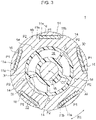
- FIG. 7 is an enlarged view illustrating the central portion in the radial direction of the mold stator 4 illustrated in FIG. 6.
- FIG. 7 illustrates both a circle representing the inner circumferential surfaces 61a and 42a of the bearing support portions 6 and 42 and a circle representing the outer circumferential surfaces 21d and 22d of the outer rings 21b and 22b of the bearings 21 and 22.
- FIG. 8 is a flux diagram illustrating a flux flow in the motor 100 including the consequent pole rotor 1.
- the consequent pole rotor 1 has the magnet magnetic poles P1 at which the permanent magnets 16 are provided and the virtual magnetic poles P2 at which the permanent magnets 16 are not provided, as described above.
- the magnetic flux density on the surface of the rotor 1 is higher at the magnet magnetic poles P1 and is lower at the virtual magnetic poles P2.
- the force acting between the magnet magnetic poles P1 and the teeth 52 is larger than the force acting between the virtual magnetic poles P2 and the teeth 52, and an excitation force in the radial direction is applied to the rotor 1.
- the excitation force in the radial direction applied to the rotor 1 is applied to the shaft 15.
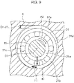
- FIG. 9 is a schematic view illustrating the shaft 15, the first bearing 21, and the bracket 6 holding the first bearing 21.
- the gap (D1-d1) between the outer circumferential surface 21d of the outer ring 21b of the first bearing 21 and the inner circumferential surface 61a of the bracket 6 is shown exaggerated in FIG. 9 .
- the inner ring 21a of the first bearing 21 is fixed to the shaft 15 by press-fitting, while the outer ring 21b is fixed to the bracket 6 by gap-fitting.
- the circumferential length of the outer circumferential surface 21d of the outer ring 21b of the first bearing 21 is a difference between the circumferential length of the inner circumferential surface 61a of the bracket 6.
- the weight of the impeller 505 attached to the shaft 15 is applied to the first bearing 21 disposed on the load side in addition to the excitation force in the radial direction generated by the rotor 1.
- the load Fr in the radial direction applied to the first bearing 21 is larger than the load Fr in the radial direction applied to the second bearing 22.
- the bearings 21 and 22 and the bearing support portions 6 and 42 are configured so that the distances D1, D2, d1, and d2 satisfy D1-d1 ⁇ D2-d2. That is, the gap on the outer circumferential side of the outer ring 21b of the first bearing 21 is narrower than the gap on the outer circumferential side of the outer ring 22b of the second bearing 22.
- the outer ring 21b of the first bearing 21 is less likely to move in the circumferential direction in the bracket 6. That is, it is possible to suppress the occurrence of the outer circumferential creep of the first bearing 21 to which the larger radial load Fr is applied.
- D1-d1 ⁇ D2-d2 is satisfied, for example, when the distances D1 and D2 satisfy D1 ⁇ D2 or when the distances d1 and d2 satisfy d1 > d2.
- the distances D1 and D2 satisfy D1 ⁇ D2.
- the distances d1 and d2 satisfy d1 > d2.
- the distance e1 from the center axis C1 to the inner circumferential surface of the inner ring 21a of the first bearing 21 and the distance e2 from the center axis C1 to the inner circumferential surface of the inner ring 22a of the second bearing 22 are the same.
- the inner diameter (2 ⁇ e1) of the first bearing 21 and the inner diameter (2 ⁇ e2) of the second bearing 22 are the same.
- the outer diameter of the portion supported by the first bearing 21 can be made equal to the outer diameter of the portion supported by the second bearing 22.
- the manufacturing cost can be reduced.
- the carrier frequency is set to a frequency higher than the audible frequency in order to suppress noise accompanying switching.
- a voltage called a shaft voltage is generated in the shaft 15 by the highfrequency induction.
- FIG. 10 is a schematic diagram for describing a current flow when the shaft current is generated. As indicated by the arrows in FIG. 10 , there are a path A1 flowing from the stator 5 to the shaft 15 via the bracket 6 and the first bearing 21, a path A2 flowing from the stator 5 to the shaft 15 via the circuit board 7 and the second bearing 22, and a path A3 flowing from the stator 5 to the shaft 15 via the rotor core 10.
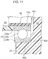
- an insulator 18 is provided between the shaft 15 and the second bearing 22, as illustrated in FIG. 11 . More specifically, the outer diameter of an end portion 15b on the counter-load side of the shaft 15 is reduced, and the cylindrical insulator 18 is attached to the end portion 15b.
- the insulator 18 is composed of a thermoplastic resin such as BMC.
- the shaft 15 and the second bearing 22 can be electrically insulated from each other by the insulator 18, the flow of the current through the path A2 can be suppressed.
- the resin part 30 is disposed between the rotor core 10 and the shaft 15, the current flow from the rotor core 10 to the shaft 15 can be suppressed. That is, the current flow through the path A3 can be suppressed.
- the current flow through the paths A2 and A3 is suppressed, so that the current flow through the path A1 is also suppressed. This makes it possible to suppress the generation of the shaft current and the occurrence of the electrolytic corrosion in the bearings 21 and 22.
- the end portion 15b of the shaft 15 can be worked to be thin and the cylindrical insulator 18 can be attached to the end portion 15b. Thus, the manufacturing cost can be reduced.
- the insulator 18 may be provided not only between the shaft 15 and the second bearing 22 but also between the shaft 15 and the first bearing 21. It is also possible to provide the insulators 18 between the shaft 15 and the first bearing 21 and between the shaft 15 and the second bearing 22.
- the motor 100 of the first embodiment includes the consequent pole rotor 1, the stator 5 surrounding the rotor 1 from outside in the radial direction, the first bearing 21 and the second bearing 22 supporting the shaft 15 of the rotor 1, the bracket 6 (first bearing support portion) having the inner circumferential surface 61a facing the outer circumferential surface 21d of the first bearing 21, and the bearing support portion 42 (second bearing support portion) having the inner circumferential surface 42a facing the outer circumferential surface 22d of the second bearing 22.
- the first bearing 21 is located on the load side
- the second bearing 22 is located on the counter-load side.
- a gap on the outer circumferential side of the first bearing 21 applied with a larger load in the radial direction is made smaller than a gap on the outer circumferential side of the other second bearing 22, and thus the outer ring 21b of the first bearing 21 can be made less likely to move in the circumferential direction. In this way, the occurrence of the outer circumferential creep can be suppressed, and the performance of the motor 100 can be improved.
- the first bearing 21 and the second bearing 22 having the same outer diameter can be used, and thus the manufacturing cost can be reduced.
- the cylindrical portion 61 of the bracket 6 and the bearing support portion 42 can be formed to have the same inner diameter, and thus the manufacturing cost can be reduced.
- the bracket 6 is composed of a metal and the bearing support portion 42 is composed of a resin, the first bearing 21 to which a larger load in the radial direction is applied can be held by the bracket 6 with high positional accuracy.
- the bearing support portion 42 is composed of a resin, the manufacturing cost can be reduced.
- the outer diameter of the portion of the shaft 15 held by the first bearing 21 and the outer diameter of the portion of the shaft 15 held by the second bearing 22 can be made the same, and thus the manufacturing cost can be reduced.
- the insulator 18 is provided between the shaft 15 and at least one of the first bearing 21 and the second bearing 22, the generation of the shaft current can be suppressed, and the occurrence of the electrolytic corrosion of the bearings 21 and 22 can be suppressed.
- the resin part 30 is provided between the rotor core 10 and the shaft 15, the generation of the shaft current can be suppressed, and the occurrence of the electrolytic corrosion in the bearings 21 and 22 can be suppressed.
- FIG. 12 is a longitudinal partial sectional view illustrating a motor 100A according to the second embodiment.
- the motor 100A of the second embodiment differs from the motor 100 of the first embodiment in the material of the rolling elements of the first bearing 21 or the rolling elements of the second bearing 22.
- the insulator 18 ( FIG. 11 ) described in the first embodiment is not provided between the shaft 15 and the second bearing 22. That is, the inner circumferential surface of the second bearing 22 is in contact with the surface of the shaft 15.
- FIG. 13(A) is an enlarged view illustrating the first bearing 21 and the second bearing 22 of the second embodiment.
- the first bearing 21 of the second embodiment includes an inner ring 21a, an outer ring 21b, and a plurality of rolling elements 21e.
- the rolling elements 21e of the first bearing 21 are composed of a ceramic.
- a ceramic is alumina (Al 2 O 3 ).
- any ceramic having strength required for the rolling element and insulating property can be used.
- the structures of the inner ring 21a and the outer ring 21b of the first bearing 21 are as described in the first embodiment.
- the structure of the second bearing 22 is as described in the first embodiment.
- the rolling elements 21e of the first bearing 21 are composed of a ceramic, the inner ring 21a and the outer ring 21b can be electrically insulated from each other. That is, the current flow through the path A1 described in the first embodiment can be suppressed.
- the current flow through the path A3 is suppressed by the resin part 30 disposed between the rotor core 10 and the shaft 15.
- the current flow through the paths A1 and A3 is suppressed, so that the current flow through the path A2 is also suppressed. This makes it possible to suppress the generation of the shaft current and the occurrence of the electrolytic corrosion in the bearings 21 and 22.
- the first bearing 21 on the load side receives a large load in the radial direction, an oil film of a lubricating oil around the rolling elements 21e tends to become thin. As the oil film is thinned, electrolytic corrosion is more likely to occur due to conduction. As the rolling elements 21e of the first bearing 21 is composed of a ceramic, the occurrence of the electrolytic corrosion can be suppressed even when the oil film is thinned.
- the rolling elements 21e of the first bearing 21 are composed of a ceramic and the rolling elements 21c of the second bearing 22 are composed of a metal.
- the rolling elements 21e of at least one of the bearings 21 and 22 are made of a ceramic.
- both the rolling elements 21e of the first bearing 21 and the rolling elements 22e of the second bearing 22 may be composed of a ceramic.
- the shaft current can be more effectively suppressed, and the effect of suppressing the occurrence of the electrolytic corrosion can be enhanced.
- the insulator 18 may be provided between the shaft 15 and the second bearing 22 as described in the first embodiment.
- the motor 100A of the second embodiment is configured in a similar manner to the motor 100 of the first embodiment, except for the points described above.
- At least one of the first bearing 21 and the second bearing 22 for holding the shaft 15 includes rolling elements composed of a ceramic. Therefore, the shaft current can be effectively suppressed, and the effect of suppressing the occurrence of the electrolytic corrosion can be enhanced.
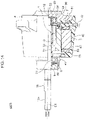
- FIG. 14 is a longitudinal partial sectional view illustrating a motor 100B according to the third embodiment.
- the motor 100B of the third embodiment is different from the motor 100 of the first embodiment in that the motor 100B includes a bearing support member 80 made of a metal and serving as a second bearing support portion and does not include the heat dissipation plate 8 ( FIG. 1 ).
- the bearing support member 80 is provided so as to cover the counter-load side of the mold stator 4.
- the bearing support member 80 is composed of a metal. More specifically, the bearing support member 80 is composed of a hot-dip zinc-aluminum-magnesium alloy plated steel sheet.
- a hot-dip zinc-aluminum-magnesium alloy plated steel sheet is advantageous in that it can be subjected to press-working and has high dimensional accuracy.
- the bearing support member 80 may alternatively be composed of an aluminum alloy such as ADC12 (JIS H5302). Since the aluminum alloy such as ADC12 can be processed by die casting, the degree of freedom of the shape is higher as compared with when extrusion molding or the like is used.
- ADC12 JIS H5302
- the bearing support member 80 has a flange portion 81 positioned on the outer side in the radial direction of the second bearing 22 and a plate-like portion 82 positioned on the counter-load side of the second bearing 22.
- FIG. 15 is an enlarged view illustrating a part of the bearing support member 80.
- An inner circumferential surface 83 in contact with the outer circumferential surface 22d of the outer ring 22b of the second bearing 22 is formed in the flange portion 81 of the bearing support member 80.
- An end surface 84 in contact with the end surface in the axial direction of the outer ring 22b and a facing surface 85 facing the end surface in the axial direction of the inner ring 22a with a space therebetween are formed on the plate-like portion 82.
- the bearing support member 80 is held by the mold resin portion 40.
- the outer circumferential side of the flange portion 81 of the bearing support member 80 is covered with the mold resin portion 40.
- the bearing support member 80 is separated from the circuit board 7, and the mold resin portion 40 is provided between the bearing support member 80 and the stator 5. That is, the bearing support member 80, the circuit board 7, and the stator 5 are not in contact with one another.
- the bearing support member 80 is composed of a metal, the inner circumferential surface 83 of the bearing support member 80 can be formed with high dimensional accuracy as is the case with the inner circumferential surface 61a of the bracket 6. Therefore, D1-d1 ⁇ D2-d2 described in the first embodiment is satisfied, and the gap (D2-d2) on the outer circumferential side of the second bearing 22 can be narrowed, and thus the occurrence of the outer circumferential creep can be suppressed.
- the bearing support member 80 Since the bearing support member 80 is in contact with the outer ring 22b but is not in contact with the inner ring 22a, the current flow between the inner ring 22a and the outer ring 22b can be suppressed.
- the bearing support member 80 is composed of a metal and a portion of the bearing support member 80 is exposed from the mold resin portion 40, the bearing support member 80 can also achieve a heat dissipation effect of dissipating heat generated in the coils 55 or the circuit board 7 to the outside.
- the motor 100B of the third embodiment is configured in a similar manner to the motor 100 of the first embodiment.
- the metal bearing support member 80 (second bearing support portion) holds the second bearing 22, the gap on the outer circumferential side of the second bearing 22 can be narrowed, and the occurrence of the outer circumferential creep of the second bearing 22 can be suppressed.
- the bracket 6 serving as the first bearing support portion is composed of a metal
- the bearing support portion 42 serving as the second bearing support portion is composed of a resin
- both the bracket 6 and the bearing support member 80 are composed of a metal
- both the first bearing support portion and the second bearing support portion may be composed of a resin such as BMC.
- the first bearing support portion may be composed of a resin
- the second bearing support portion may be composed of a metal.
- FIG. 16 (A) is a diagram illustrating the configuration of an air conditioner 500 to which the motor 100 of the first embodiment is applied.
- the air conditioner 500 includes an outdoor unit 501, an indoor unit 502, and a refrigerant pipe 503 connecting the units 501 and 502.
- the outdoor unit 501 includes an outdoor fan 510 such as a propeller fan, a compressor 504, and a heat exchanger 507.
- the outdoor fan 510 includes an impeller 505 and a motor 100 for driving the impeller 505.
- the configuration of the motor 100 is as described above in the first embodiment.
- FIG. 16(B) is a sectional view of the outdoor unit 501.
- the motor 100 is attached to a frame 509 disposed inside a housing 508 of the outdoor unit 501 by screws 48.
- the impeller 505 is attached to the shaft 15 of the motor 100 via a hub 506.
- the impeller 505 is rotated by the rotation of the motor 100 and blows air to the heat exchanger 507.
- the heat released when the refrigerant compressed in the compressor 504 is condensed in the heat exchanger 507 (condenser) is released to the outside of the room by the air blowing by the outdoor fan 510.
- the indoor unit 502 ( FIG. 16(A) ) includes an indoor fan 520 which is, for example, a cross flow fan, and a heat exchanger 523.
- the indoor fan 520 includes an impeller 521 and a motor 522 for driving the impeller 521.
- the impeller 521 is rotated by the rotation of the motor 522 and blows air into the room.
- the air deprived of heat when the refrigerant evaporates in the heat exchanger 523 (evaporator) is blown into the room by the air blowing by the indoor fan 520.
- the outer circumferential creep is suppressed.
- the operation of the outdoor fan 510 can be stabilized for a long period of time, and thus the reliability of the air conditioner 500 can be improved.
- the motor 100 of the first embodiment is used for the outdoor fan 510 in this example, but it is sufficient that the motor 100 of the first embodiment is used for at least one of the outdoor fan 510 and the indoor fan 520. In place of the motor 100 of the first embodiment, any of the motors 100A and 100B of the second and third embodiments may be used.
- the motors 100, 100A, and 100B described in the first to third embodiments may also be mounted on electrical equipment other than the fan of an air conditioner.
Landscapes
- Engineering & Computer Science (AREA)
- Power Engineering (AREA)
- Chemical & Material Sciences (AREA)
- Combustion & Propulsion (AREA)
- Mechanical Engineering (AREA)
- General Engineering & Computer Science (AREA)
- Motor Or Generator Frames (AREA)
- Devices For Blowing Cold Air, Devices For Blowing Warm Air, And Means For Preventing Water Condensation In Air Conditioning Units (AREA)
Abstract
Description
- The present disclosure relates to a motor, a fan, and an air conditioner.
- A motor includes a rotor having a shaft, and a stator. A bearing that supports the shaft is held by a bearing support portion such as a bracket (for example, see Patent Document 1).
- Patent Document 1:
Japanese Utility Model Publication No. 60-141651 FIG. 1 ) - Recently, a consequent pole rotor has been developed in which a permanent magnet forms a magnet magnetic pole, and a part of a rotor core forms a virtual magnetic pole. In the consequent pole rotor, the magnet magnetic pole and the virtual magnetic pole have different magnetic flux densities on the rotor surface, and thus an excitation force in the radial direction is likely to be applied to the rotor. As a result, a load in the radial direction applied to a bearing that supports a shaft tends to increase.
- If a large load in the radial direction is applied to the bearing supporting the shaft, outer circumferential creep may occur. The outer circumferential creep is a phenomenon in which an outer ring of the bearing moves in the circumferential direction relative to the bearing support portion. Since the outer circumferential creep leads to wear of the bearing, it is required to suppress the occurrence of the outer circumferential creep.
- The present invention is made to solve the above-described problem, and has an object to suppress the occurrence of the outer circumferential creep.
- A motor according to the present disclosure includes a rotor having a shaft, a rotor core surrounding the shaft from outside in a radial direction about a center axis of the shaft, and a permanent magnet attached to the rotor core, the permanent magnet forming a magnet magnetic pole, a part of the rotor core forming a virtual magnetic pole, a stator surrounding the rotor from outside in the radial direction, a first bearing and a second bearing supporting the shaft, a first bearing support portion having an inner circumferential surface facing an outer circumferential surface of the first bearing, and a second bearing support portion having an inner circumferential surface facing an outer circumferential surface of the second bearing. One side of the shaft in a direction of the center axis is defined as a load side to which a load is applied. Of the first bearing and the second bearing, the first bearing is located on the load side. A distance D1 from the center axis to the inner circumferential surface of the first bearing support portion, a distance D2 from the center axis to the inner circumferential surface of the second bearing support portion, a distance d1 from the center axis to the outer circumferential surface of the first bearing, and a distance d2 from the center axis to the outer circumferential surface of the second bearing satisfy D1-d1 < D2-d2.
- In the present disclosure, since the distances D1, D2, d1, and d2 satisfy D1-d1 < D2-d2, the outer ring of the first bearing applied with a larger load in the radial direction is less likely to move in the circumferential direction. Therefore, the occurrence of the outer circumferential creep can be suppressed.
-
-
FIG. 1 is a longitudinal partial sectional view illustrating a motor according to a first embodiment. -
FIG. 2 is a cross-sectional view illustrating the motor according to the first embodiment. -
FIG. 3 is a cross-sectional view illustrating a rotor according to the first embodiment. -
FIG. 4 is a longitudinal partial sectional view illustrating the motor according to the first embodiment. -
FIG. 5(A) is a diagram illustrating a first bearing and a first bearing support portion of the first embodiment, andFIG. 5(B) is a diagram illustrating a second bearing and a second bearing support portion. -
FIG. 6 is a view of a mold stator according to the first embodiment as viewed from the load side. -
FIG. 7 is an enlarged view illustrating a part of the motor ofFIG. 6 . -
FIG. 8 is a flux diagram illustrating the flow of magnetic flux in the motor. -
FIG. 9 is a schematic diagram illustrating a shaft, the first bearing, and a bracket. -
FIG. 10 is a diagram illustrating a configuration for suppressing a shaft current in the first embodiment. -
FIG. 11 is a sectional view illustrating the shaft and the second bearing of the first embodiment. -
FIG. 12 is a longitudinal partial sectional view illustrating a motor according to a second embodiment. -
FIG. 13(A) is a diagram illustrating a first bearing and a second bearing of the second embodiment, andFIG. 13(B) is a diagram illustrating another example of the first bearing and the second bearing. -
FIG. 14 is a longitudinal sectional view illustrating a motor according to a third embodiment. -
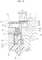
FIG. 15 is an enlarged longitudinal sectional view illustrating a part of the motor according to the third embodiment. -
FIG. 16(A) is a diagram illustrating an air conditioner to which the motor of each embodiment is applicable, andFIG. 16(B) is a sectional view illustrating an outdoor unit of the air conditioner. -
FIG. 1 is a longitudinal sectional view illustrating amotor 100 according to the first embodiment. Themotor 100 is used, for example, for a fan of an air conditioner. Themotor 100 is an interior permanent magnet (IPM) motor in whichpermanent magnets 16 are embedded in arotor 1. - The
motor 100 includes therotor 1 having ashaft 15 which is a rotary shaft, and amold stator 4 surrounding therotor 1. Themold stator 4 includes astator 5 provided to surround therotor 1, and amold resin portion 40 covering thestator 5. - In the following description, the direction of the center axis C1 of the
shaft 15 is referred to as an "axial direction." The circumferential direction about the center axis C1 is referred to as a "circumferential direction" and is indicated by an arrow R1 inFIG. 2 and other figures. The radial direction about the center axis C1 is referred to as a "radial direction." A sectional view in a plane parallel to the axial direction is referred to as a "longitudinal sectional view," and a sectional view in a plane orthogonal to the axial direction is referred to as a "cross-sectional view." - The
shaft 15 receives a load on one side in the axial direction. More specifically, theshaft 15 protrudes from themold stator 4 to the left side inFIG. 1 , and, for example, animpeller 505 of a fan (FIG. 16(A) ) is attached to anattachment portion 15a formed at the tip of theshaft 15 on the protruding side. Thus, the protruding side of theshaft 15 is referred to as a "load side" and the opposite side of theshaft 15 is referred to as a "counter-load side." - The
mold stator 4 includes thestator 5 and themold resin portion 40, as described above. Themold resin portion 40 is composed of a thermosetting resin such as a bulk molding compound (BMC). Alternatively, themold resin portion 40 may be composed of a thermoplastic resin such as polybutylene terephthalate (PBT) or polyphenylene sulfide (PPS). - The
mold resin portion 40 hasattachment legs 45 on its outer circumference. In this example, fourattachment legs 45 are formed at equal intervals in the circumferential direction. Holes 46 (FIG. 6 ) through which screws are inserted are formed in theattachment legs 45. Theattachment legs 45 are fixed to, for example, a frame of an outdoor unit of the air conditioner with screws inserted through theholes 46. - The
mold resin portion 40 has anopening 41 on the load side. Therotor 1 is inserted into the hollow portion inside themold stator 4 through theopening 41. Abracket 6 serving as a first bearing support portion is attached to the opening 41 of themold resin portion 40. Thebracket 6 is composed of a metal such as a galvanized steel sheet. Thebracket 6 is fitted to anannular step portion 41a formed around theopening 41. - The
bracket 6 holds afirst bearing 21 that supports theshaft 15. Awaterproof cap 9 for preventing water or the like from entering thefirst bearing 21 is attached to theshaft 15 so as to surround thebracket 6 from outside. - The
mold resin portion 40 has abearing support portion 42 serving as a second bearing support portion on the counter-load side. Thebearing support portion 42 of themold resin portion 40 holds asecond bearing 22 that supports theshaft 15. - A
circuit board 7 is disposed on the outer side of thesecond bearing 22 in the radial direction. Thecircuit board 7 is covered with and held by themold resin portion 40. Adevice 71 such as a power transistor for driving themotor 100, a magnetic sensor, and the like are mounted on thecircuit board 7. Leadwires 73 are wired on thecircuit board 7. Thelead wires 73 on thecircuit board 7 are drawn out to the outside of themotor 100 through anoutlet part 72 attached to an outer circumferential portion of themold resin portion 40. - A
heat dissipation plate 8 is provided so as to cover the counter-load side of themold resin portion 40. Theheat dissipation plate 8 is partially covered with themold resin portion 40 and partially exposed from themold resin portion 40. Theheat dissipation plate 8 dissipates heat generated by themotor 100 to the outside. It is also possible not to provide theheat dissipation plate 8. -
FIG. 2 is a cross-sectional view illustrating themotor 100. As illustrated inFIG. 2 , thestator 5 includes astator core 50, an insulatingportion 53 provided on thestator core 50, and coils 55 wound on thestator core 50 via the insulatingportion 53. Thestator core 50 is formed by stacking a plurality of electromagnetic steel sheets in the axial direction and fixing them by crimping or the like. The thickness of each electromagnetic steel sheet is, for example, 0.2 to 0.5 mm. - The
stator core 50 includes ayoke 51 in an annular shape about the center axis C1 and a plurality ofteeth 52 extending inward in the radial direction from theyoke 51. Theteeth 52 are arranged at equal intervals in the circumferential direction. The number ofteeth 52 is 12 in this example, but is not limited to 12. Slots that are spaces for accommodating thecoils 55 are formed each betweenadjacent teeth 52. - The insulating
portion 53, which is made of, for example, polybutylene terephthalate (PBT), is attached to thestator core 50. The insulatingportion 53 is composed of a thermoplastic resin such as PBT. The insulatingportion 53 is obtained by molding the thermoplastic resin integrally with thestator core 50 or assembling a molded body of the thermoplastic resin to thestator core 50. -
FIG. 3 is a cross-sectional view illustrating therotor 1. As illustrated inFIG. 3 , therotor 1 includes theshaft 15, arotor core 10 surrounding theshaft 15 from outside in the radial direction, and the plurality ofpermanent magnets 16 embedded in therotor core 10. - The
rotor core 10 is a member in an annular shape about the center axis C1. Therotor core 10 is formed by stacking a plurality of electromagnetic steel sheets in the axial direction and fixing them by crimping or the like. The thickness of each electromagnetic steel sheet is, for example, 0.2 to 0.5 mm. - The
rotor core 10 has a plurality ofmagnet insertion holes 11a. Themagnet insertion holes 11a are arranged at equal intervals in the circumferential direction and at equal distances from the center axis C1. In this example, the number of themagnet insertion holes 11a is five. Themagnet insertion holes 11a are formed along the outer circumference of therotor core 10. - Each
magnet insertion hole 11a extends linearly in a direction orthogonal to a line in the radial direction (referred to as a magnetic pole center line) passing through a pole center, i.e., the center of themagnet insertion hole 11a in the circumferential direction. However, themagnet insertion hole 11a is not limited to such a shape, and may extend, for example, in a V-shape. -
Flux barriers 11b which are holes are formed at both ends of eachmagnet insertion hole 11a in the circumferential direction. Thin portions are formed between theflux barriers 11b and the outer circumference of therotor core 10. To suppress the leakage flux between adjacent magnetic poles, the thickness of the thin portion is desirably the same as the thickness of each electromagnetic steel sheet of therotor core 10. - The
permanent magnets 16 are inserted into themagnet insertion holes 11a. Eachpermanent magnet 16 is in the form of a flat plate and has a rectangular cross-sectional shape in a plane orthogonal to the axial direction. Thepermanent magnet 16 is composed of a rare earth magnet. More specifically, thepermanent magnet 16 is composed of a neodymium sintered magnet containing Nd (neodymium)-Fe (iron)-B (boron). - The
permanent magnets 16 are arranged so that the same magnetic poles (for example, N poles) face the outer circumferential side of therotor core 10. In therotor core 10, magnetic poles (for example, S poles) opposite to the permanent magnets are formed in the regions each between the permanent magnets adjacent to each other in the circumferential direction. - Thus, the
rotor 1 includes five magnet magnetic poles P1 formed by thepermanent magnets 16 and five virtual magnetic poles P2 formed by therotor core 10. Such a configuration is referred to as a consequent pole type. Hereinafter, when the term "magnetic pole" is simply used, it refers to either the magnetic pole P1 or the virtual pole P2. Therotor 1 has 10 magnetic poles. - Although the number of poles of the
rotor 1 is 10 in this example, the number of poles of therotor 1 may be four or any larger even number. Although onepermanent magnet 16 is disposed in eachmagnet insertion hole 11a in this example, two or morepermanent magnets 16 may be disposed in eachmagnet insertion hole 11a. The magnetic poles P1 may be S poles, and the virtual poles P2 may be N poles. - The outer circumference of the
rotor core 10 has a so-called flower shape in a plane orthogonal to the axial direction. In other words, the outer circumference of therotor core 10 has a maximum outer diameter at the pole center of each of the magnetic poles P1 and P2 and a minimum outer diameter at each inter-pole portion M, and extends in an arc shape from the pole center to the inter-pole portion M. The shape of the outer circumference of therotor core 10 is not limited to the flower shape, but may be a circular shape. - In the
rotor core 10, crimpingportions 14 are provided on the inner side of themagnet insertion holes 11a in the radial direction. The crimpingportions 14 are portions by which the electromagnetic steel sheets constituting therotor core 10 are fixed. - A
resin part 30 is provided between the inner circumference of therotor core 10 and theshaft 15. Theresin part 30 is composed of, for example, a resin such as polybutylene terephthalate (PBT). Theresin part 30 has an annular innercylindrical portion 31 fixed to theshaft 15, an annular outercylindrical portion 33 fixed to the inner circumference of therotor core 10, and a plurality ofribs 32 connecting the innercylindrical portion 31 and the outercylindrical portion 33. - The
shaft 15 is fixed inside the innercylindrical portion 31 of theresin part 30. Theribs 32 are arranged at equal intervals in the circumferential direction and extend radially outward in the radial direction from the innercylindrical portion 31. Hollow portions are formed each between theribs 32 adjacent to each other in the circumferential direction. In this example, the number ofribs 32 is half the number of poles, and the positions of theribs 32 in the circumferential direction coincide with the pole centers of the virtual magnetic poles P2, but the number and arrangement of theribs 32 are not limited to the examples described above. - With reference to
FIG. 1 again, asensor magnet 17 is disposed on the counter-load side of therotor core 10. Thesensor magnet 17 is held by theresin part 30. The magnetic field of thesensor magnet 17 is detected by a magnetic sensor mounted on thecircuit board 7, whereby the rotational position of therotor 1 is detected. - Nest, the
bearings shaft 15 and a supporting structure for thebearings FIG. 4 is a longitudinal partial sectional view illustrating themotor 100. Theshaft 15 is rotatably supported by thefirst bearing 21 and thesecond bearing 22, as described above. Thefirst bearing 21 is disposed on the load side, and thesecond bearing 22 is disposed on the counter-load side. - The
first bearing 21 includes aninner ring 21a, anouter ring 21b, and a plurality of rollingelements 21c. Theinner ring 21a is fixed to theshaft 15 by press-fitting. Theouter ring 21b is fixed to a cylindrical portion 61 (described below) of thebracket 6 by gap-fitting. The rollingelements 21c are, for example, balls and are disposed between theinner ring 21a and theouter ring 21b. Each of theinner ring 21a, theouter ring 21b, and the rollingelements 21c is composed of a metal. - The
second bearing 22 includes aninner ring 22a, anouter ring 22b, and a plurality of rollingelements 22c. Theinner ring 22a is fixed to theshaft 15 by press-fitting. Theouter ring 22b is fixed to thebearing support portion 42 of themold resin portion 40 by gap-fitting. The rollingelements 22c are, for example, balls and are disposed between theinner ring 22a and theouter ring 22b. Each of theinner ring 22a, theouter ring 22b, and the rollingelements 22c is composed of a metal. -
FIG. 5(A) is a sectional view illustrating thefirst bearing 21 and thebracket 6. Thebracket 6 has acylindrical portion 61 surrounding thefirst bearing 21 and aflange portion 62 extending outward in the radial direction from thecylindrical portion 61. The innercircumferential surface 61a of thecylindrical portion 61 faces an outercircumferential surface 21d of theouter ring 21b of the first bearing 21 (also referred to as the outercircumferential surface 21d of the first bearing 21). - An annular
fitting portion 63 is formed on the outer circumference of theflange portion 62, and thefitting portion 63 is fitted to thestep portion 41a (FIG. 4 ) of themold resin portion 40. Thebracket 6 is fixed to themold resin portion 40 by fitting thefitting portion 63 to thestep portion 41a. - The
bracket 6 further has anend surface portion 64 facing the end surface of thefirst bearing 21 in the axial direction. Ashaft insertion hole 65 through which theshaft 15 passes is formed at the center of theend surface portion 64. Awasher 66 that urges theouter ring 21b of thefirst bearing 21 in the axial direction is disposed between theend surface portion 64 and thefirst bearing 21. - The distance from the center axis C1 to the outer
circumferential surface 21d of theouter ring 21b of thefirst bearing 21 is defined as a distance d1. The distance from the center axis C1 to the innercircumferential surface 61a of thecylindrical portion 61 of thebracket 6 is defined as a distance D1. The distance D1 is larger than the distance d1. - The difference (D1-d1) between the distance D1 and the distance d1 is a gap between the outer
circumferential surface 21d of theouter ring 21b of thefirst bearing 21 and the innercircumferential surface 61a of thecylindrical portion 61 of thebracket 6 and is, for example, 5 µm. -
FIG. 5(B) is a sectional view illustrating thesecond bearing 22 and thebearing support portion 42. Thebearing support portion 42 has an innercircumferential surface 42a surrounding thesecond bearing 22 and anend surface 42b in contact with theouter ring 22b of thesecond bearing 22 in the axial direction. The innercircumferential surface 42a of thebearing support portion 42 faces an outercircumferential surface 22d of theouter ring 22b of the second bearing 22 (also referred to as the outercircumferential surface 22d of the second bearing 22). - The distance from the center axis C1 to the outer
circumferential surface 22d of theouter ring 22b of thesecond bearing 22 is defined as a distance d2. The distance from the center axis C1 to the innercircumferential surface 42a of thebearing support portion 42 is defined as a distance D2. The distance D2 is larger than the distance d2. - The difference (D2-d2) between the distance D2 and the distance d2 is a gap between the outer
circumferential surface 22d of theouter ring 22b of thesecond bearing 22 and the innercircumferential surface 42a of thebearing support portion 42 and is, for example, 10 µm. - In the first embodiment, D1-d1 < D2-d2 is satisfied. That is, the gap on the outer circumferential side of the
outer ring 21b of thefirst bearing 21 on the load side is narrower than the gap on the outer circumferential side of theouter ring 22b of thesecond bearing 22 on the counter-load side. -
FIG. 6 is a view of themold stator 4 as viewed from the load side. InFIG. 6 , therotor 1 is not yet inserted into themold stator 4, and thus thebearing support portion 42 is exposed through theopening 41 of themold resin portion 40. -
FIG. 7 is an enlarged view illustrating the central portion in the radial direction of themold stator 4 illustrated inFIG. 6. FIG. 7 illustrates both a circle representing the innercircumferential surfaces bearing support portions circumferential surfaces outer rings bearings - Next, the operation of the first embodiment will be described.
FIG. 8 is a flux diagram illustrating a flux flow in themotor 100 including theconsequent pole rotor 1. - The
consequent pole rotor 1 has the magnet magnetic poles P1 at which thepermanent magnets 16 are provided and the virtual magnetic poles P2 at which thepermanent magnets 16 are not provided, as described above. The magnetic flux density on the surface of therotor 1 is higher at the magnet magnetic poles P1 and is lower at the virtual magnetic poles P2. - As a result, the force acting between the magnet magnetic poles P1 and the
teeth 52 is larger than the force acting between the virtual magnetic poles P2 and theteeth 52, and an excitation force in the radial direction is applied to therotor 1. The excitation force in the radial direction applied to therotor 1 is applied to theshaft 15. -
FIG. 9 is a schematic view illustrating theshaft 15, thefirst bearing 21, and thebracket 6 holding thefirst bearing 21. In this regard, the gap (D1-d1) between the outercircumferential surface 21d of theouter ring 21b of thefirst bearing 21 and the innercircumferential surface 61a of thebracket 6 is shown exaggerated inFIG. 9 . - The
inner ring 21a of thefirst bearing 21 is fixed to theshaft 15 by press-fitting, while theouter ring 21b is fixed to thebracket 6 by gap-fitting. Thus, there is a difference between the circumferential length of the outercircumferential surface 21d of theouter ring 21b of thefirst bearing 21 and the circumferential length of the innercircumferential surface 61a of thebracket 6. - When the
shaft 15 rotates in the direction indicated by the arrow R2 in a state in which the load Fr in the radial direction is applied to thefirst bearing 21, theouter ring 21b moves in the circumferential direction relative to the innercircumferential surface 61a of thebracket 6 as indicated by the arrow F1 due to the load Fr in the radial direction and the difference in the circumferential lengths. This phenomenon is referred to as outer circumferential creep. - In particular, the weight of the
impeller 505 attached to theshaft 15 is applied to thefirst bearing 21 disposed on the load side in addition to the excitation force in the radial direction generated by therotor 1. Thus, the load Fr in the radial direction applied to thefirst bearing 21 is larger than the load Fr in the radial direction applied to thesecond bearing 22. - In the first embodiment, the
bearings bearing support portions outer ring 21b of thefirst bearing 21 is narrower than the gap on the outer circumferential side of theouter ring 22b of thesecond bearing 22. - Thus, the
outer ring 21b of thefirst bearing 21 is less likely to move in the circumferential direction in thebracket 6. That is, it is possible to suppress the occurrence of the outer circumferential creep of thefirst bearing 21 to which the larger radial load Fr is applied. - It is conceivable that the relationship D1-d1 < D2-d2 is satisfied, for example, when the distances D1 and D2 satisfy D1 < D2 or when the distances d1 and d2 satisfy d1 > d2.
- For example, if the inner diameter of the
cylindrical portion 61 of thebracket 6 is made smaller than the inner diameter of thebearing support portion 42, the distances D1 and D2 satisfy D1 < D2. In such a case, as long as D1-d1 < D2-d2 is satisfied, a large/small relationship between the distances d1 and d2 does not matter. For example, the distances d1 and d2 may be the same (d1 = d2). With this configuration, thebearings - If the outer diameter of the
outer ring 21b of thefirst bearing 21 is larger than the outer diameter of theouter ring 22b of thesecond bearing 22, the distances d1 and d2 satisfy d1 > d2. In such a case, as long as D1-d1 < D2-d2 is satisfied, a large/small relationship between the distances D1 and D2 does not matter. For example, the distances D1 and D2 may be the same (D1 = D2). With this configuration, thecylindrical portion 61 of thebracket 6 and thebearing support portion 42 can be made to have the same inner diameter, and thereby the manufacturing cost can be reduced. - As illustrated in
FIGS. 5(A) and 5(B) , the distance e1 from the center axis C1 to the inner circumferential surface of theinner ring 21a of thefirst bearing 21 and the distance e2 from the center axis C1 to the inner circumferential surface of theinner ring 22a of thesecond bearing 22 are the same. In other words, the inner diameter (2 × e1) of thefirst bearing 21 and the inner diameter (2 × e2) of thesecond bearing 22 are the same. - Thus, in the
shaft 15, the outer diameter of the portion supported by thefirst bearing 21 can be made equal to the outer diameter of the portion supported by thesecond bearing 22. Thus, the manufacturing cost can be reduced. - Suppression of a shaft current in the
motor 100 will now be described. When themotor 100 is driven by an inverter, the carrier frequency is set to a frequency higher than the audible frequency in order to suppress noise accompanying switching. However, as the carrier frequency increases, a voltage called a shaft voltage is generated in theshaft 15 by the highfrequency induction. - When the shaft voltage increases, the potential difference between the
inner rings outer rings bearings shaft 15 increases, and the current is likely to flow to theshaft 15 through thebearings inner rings outer rings elements -
FIG. 10 is a schematic diagram for describing a current flow when the shaft current is generated. As indicated by the arrows inFIG. 10 , there are a path A1 flowing from thestator 5 to theshaft 15 via thebracket 6 and thefirst bearing 21, a path A2 flowing from thestator 5 to theshaft 15 via thecircuit board 7 and thesecond bearing 22, and a path A3 flowing from thestator 5 to theshaft 15 via therotor core 10. - In the first embodiment, an
insulator 18 is provided between theshaft 15 and thesecond bearing 22, as illustrated inFIG. 11 . More specifically, the outer diameter of anend portion 15b on the counter-load side of theshaft 15 is reduced, and thecylindrical insulator 18 is attached to theend portion 15b. Theinsulator 18 is composed of a thermoplastic resin such as BMC. - Since the
shaft 15 and thesecond bearing 22 can be electrically insulated from each other by theinsulator 18, the flow of the current through the path A2 can be suppressed. - In the
rotor 1, since theresin part 30 is disposed between therotor core 10 and theshaft 15, the current flow from therotor core 10 to theshaft 15 can be suppressed. That is, the current flow through the path A3 can be suppressed. - Of the three current paths A1, A2, and A3, the current flow through the paths A2 and A3 is suppressed, so that the current flow through the path A1 is also suppressed. This makes it possible to suppress the generation of the shaft current and the occurrence of the electrolytic corrosion in the
bearings - Since the
insulator 18 is attached to theend portion 15b of theshaft 15, theend portion 15b of theshaft 15 can be worked to be thin and thecylindrical insulator 18 can be attached to theend portion 15b. Thus, the manufacturing cost can be reduced. - The
insulator 18 may be provided not only between theshaft 15 and thesecond bearing 22 but also between theshaft 15 and thefirst bearing 21. It is also possible to provide theinsulators 18 between theshaft 15 and thefirst bearing 21 and between theshaft 15 and thesecond bearing 22. - As described above, the
motor 100 of the first embodiment includes theconsequent pole rotor 1, thestator 5 surrounding therotor 1 from outside in the radial direction, thefirst bearing 21 and thesecond bearing 22 supporting theshaft 15 of therotor 1, the bracket 6 (first bearing support portion) having the innercircumferential surface 61a facing the outercircumferential surface 21d of thefirst bearing 21, and the bearing support portion 42 (second bearing support portion) having the innercircumferential surface 42a facing the outercircumferential surface 22d of thesecond bearing 22. Thefirst bearing 21 is located on the load side, and thesecond bearing 22 is located on the counter-load side. The distance D1 from the center axis C1 to the innercircumferential surface 61a of thebracket 6, the distance D2 from the center axis C1 to the innercircumferential surface 42a of thebearing support portion 42, the distance d1 from the center axis C1 to the outercircumferential surface 21d of thefirst bearing 21, and the distance d2 from the center axis C1 to the outercircumferential surface 22d of thesecond bearing 22 satisfy D1-d1 < D2-d2. - With this configuration, a gap on the outer circumferential side of the
first bearing 21 applied with a larger load in the radial direction is made smaller than a gap on the outer circumferential side of the othersecond bearing 22, and thus theouter ring 21b of thefirst bearing 21 can be made less likely to move in the circumferential direction. In this way, the occurrence of the outer circumferential creep can be suppressed, and the performance of themotor 100 can be improved. - When the distance D1 is smaller than the distance D2, the
first bearing 21 and thesecond bearing 22 having the same outer diameter can be used, and thus the manufacturing cost can be reduced. - When the distance d1 is larger than the distance d2, the
cylindrical portion 61 of thebracket 6 and thebearing support portion 42 can be formed to have the same inner diameter, and thus the manufacturing cost can be reduced. - Since the
bracket 6 is composed of a metal and thebearing support portion 42 is composed of a resin, thefirst bearing 21 to which a larger load in the radial direction is applied can be held by thebracket 6 with high positional accuracy. When thebearing support portion 42 is composed of a resin, the manufacturing cost can be reduced. - Since the inner diameter of the
first bearing 21 and the inner diameter of thesecond bearing 22 are the same, the outer diameter of the portion of theshaft 15 held by thefirst bearing 21 and the outer diameter of the portion of theshaft 15 held by thesecond bearing 22 can be made the same, and thus the manufacturing cost can be reduced. - Since the
insulator 18 is provided between theshaft 15 and at least one of thefirst bearing 21 and thesecond bearing 22, the generation of the shaft current can be suppressed, and the occurrence of the electrolytic corrosion of thebearings - Since the
resin part 30 is provided between therotor core 10 and theshaft 15, the generation of the shaft current can be suppressed, and the occurrence of the electrolytic corrosion in thebearings - Next, the second embodiment will be described.
FIG. 12 is a longitudinal partial sectional view illustrating amotor 100A according to the second embodiment. Themotor 100A of the second embodiment differs from themotor 100 of the first embodiment in the material of the rolling elements of thefirst bearing 21 or the rolling elements of thesecond bearing 22. - As illustrated in
FIG. 12 , the insulator 18 (FIG. 11 ) described in the first embodiment is not provided between theshaft 15 and thesecond bearing 22. That is, the inner circumferential surface of thesecond bearing 22 is in contact with the surface of theshaft 15. -
FIG. 13(A) is an enlarged view illustrating thefirst bearing 21 and thesecond bearing 22 of the second embodiment. Thefirst bearing 21 of the second embodiment includes aninner ring 21a, anouter ring 21b, and a plurality of rollingelements 21e. - The rolling
elements 21e of thefirst bearing 21 are composed of a ceramic. An example of the ceramic is alumina (Al2O3). However, besides alumina, any ceramic having strength required for the rolling element and insulating property can be used. - The structures of the
inner ring 21a and theouter ring 21b of thefirst bearing 21 are as described in the first embodiment. The structure of thesecond bearing 22 is as described in the first embodiment. - Since the rolling
elements 21e of thefirst bearing 21 are composed of a ceramic, theinner ring 21a and theouter ring 21b can be electrically insulated from each other. That is, the current flow through the path A1 described in the first embodiment can be suppressed. - As described in the first embodiment, the current flow through the path A3 is suppressed by the
resin part 30 disposed between therotor core 10 and theshaft 15. - Of the three current paths A1, A2, and A3, the current flow through the paths A1 and A3 is suppressed, so that the current flow through the path A2 is also suppressed. This makes it possible to suppress the generation of the shaft current and the occurrence of the electrolytic corrosion in the
bearings - Since the
first bearing 21 on the load side receives a large load in the radial direction, an oil film of a lubricating oil around the rollingelements 21e tends to become thin. As the oil film is thinned, electrolytic corrosion is more likely to occur due to conduction. As the rollingelements 21e of thefirst bearing 21 is composed of a ceramic, the occurrence of the electrolytic corrosion can be suppressed even when the oil film is thinned. - In this example, the rolling
elements 21e of thefirst bearing 21 are composed of a ceramic and the rollingelements 21c of thesecond bearing 22 are composed of a metal. However, it is sufficient that the rollingelements 21e of at least one of thebearings - For example, as illustrated in
FIG. 13(B) , both therolling elements 21e of thefirst bearing 21 and the rollingelements 22e of thesecond bearing 22 may be composed of a ceramic. With this configuration, the shaft current can be more effectively suppressed, and the effect of suppressing the occurrence of the electrolytic corrosion can be enhanced. - The
insulator 18 may be provided between theshaft 15 and thesecond bearing 22 as described in the first embodiment. - The
motor 100A of the second embodiment is configured in a similar manner to themotor 100 of the first embodiment, except for the points described above. - As described above, in the second embodiment, at least one of the
first bearing 21 and thesecond bearing 22 for holding theshaft 15 includes rolling elements composed of a ceramic. Therefore, the shaft current can be effectively suppressed, and the effect of suppressing the occurrence of the electrolytic corrosion can be enhanced. - Next, the third embodiment will be described.
FIG. 14 is a longitudinal partial sectional view illustrating amotor 100B according to the third embodiment. Themotor 100B of the third embodiment is different from themotor 100 of the first embodiment in that themotor 100B includes abearing support member 80 made of a metal and serving as a second bearing support portion and does not include the heat dissipation plate 8 (FIG. 1 ). - The
bearing support member 80 is provided so as to cover the counter-load side of themold stator 4. Thebearing support member 80 is composed of a metal. More specifically, the bearingsupport member 80 is composed of a hot-dip zinc-aluminum-magnesium alloy plated steel sheet. A hot-dip zinc-aluminum-magnesium alloy plated steel sheet is advantageous in that it can be subjected to press-working and has high dimensional accuracy. - The
bearing support member 80 may alternatively be composed of an aluminum alloy such as ADC12 (JIS H5302). Since the aluminum alloy such as ADC12 can be processed by die casting, the degree of freedom of the shape is higher as compared with when extrusion molding or the like is used. - The
bearing support member 80 has aflange portion 81 positioned on the outer side in the radial direction of thesecond bearing 22 and a plate-like portion 82 positioned on the counter-load side of thesecond bearing 22. -
FIG. 15 is an enlarged view illustrating a part of thebearing support member 80. An innercircumferential surface 83 in contact with the outercircumferential surface 22d of theouter ring 22b of thesecond bearing 22 is formed in theflange portion 81 of thebearing support member 80. Anend surface 84 in contact with the end surface in the axial direction of theouter ring 22b and a facingsurface 85 facing the end surface in the axial direction of theinner ring 22a with a space therebetween are formed on the plate-like portion 82. - The
bearing support member 80 is held by themold resin portion 40. The outer circumferential side of theflange portion 81 of thebearing support member 80 is covered with themold resin portion 40. Thebearing support member 80 is separated from thecircuit board 7, and themold resin portion 40 is provided between the bearingsupport member 80 and thestator 5. That is, the bearingsupport member 80, thecircuit board 7, and thestator 5 are not in contact with one another. - Since the
bearing support member 80 is composed of a metal, the innercircumferential surface 83 of thebearing support member 80 can be formed with high dimensional accuracy as is the case with the innercircumferential surface 61a of thebracket 6. Therefore, D1-d1 < D2-d2 described in the first embodiment is satisfied, and the gap (D2-d2) on the outer circumferential side of thesecond bearing 22 can be narrowed, and thus the occurrence of the outer circumferential creep can be suppressed. - Since a part of the
bearing support member 80 is covered with themold resin portion 40 and is not in contact with thecircuit board 7 and thestator 5, the generation of the shaft current can be suppressed. - Since the
bearing support member 80 is in contact with theouter ring 22b but is not in contact with theinner ring 22a, the current flow between theinner ring 22a and theouter ring 22b can be suppressed. - Since the
bearing support member 80 is composed of a metal and a portion of thebearing support member 80 is exposed from themold resin portion 40, the bearingsupport member 80 can also achieve a heat dissipation effect of dissipating heat generated in thecoils 55 or thecircuit board 7 to the outside. - Except for the points described above, the
motor 100B of the third embodiment is configured in a similar manner to themotor 100 of the first embodiment. - As described above, in the third embodiment, since the metal bearing support member 80 (second bearing support portion) holds the
second bearing 22, the gap on the outer circumferential side of thesecond bearing 22 can be narrowed, and the occurrence of the outer circumferential creep of thesecond bearing 22 can be suppressed. - In the first embodiment, the
bracket 6 serving as the first bearing support portion is composed of a metal, and thebearing support portion 42 serving as the second bearing support portion is composed of a resin. In the third embodiment, both thebracket 6 and thebearing support member 80 are composed of a metal. However, both the first bearing support portion and the second bearing support portion may be composed of a resin such as BMC. Alternatively, the first bearing support portion may be composed of a resin, and the second bearing support portion may be composed of a metal. - Next, an air conditioner to which the above-described
motors FIG. 16 (A) is a diagram illustrating the configuration of anair conditioner 500 to which themotor 100 of the first embodiment is applied. Theair conditioner 500 includes anoutdoor unit 501, anindoor unit 502, and arefrigerant pipe 503 connecting theunits - The
outdoor unit 501 includes anoutdoor fan 510 such as a propeller fan, acompressor 504, and aheat exchanger 507. Theoutdoor fan 510 includes animpeller 505 and amotor 100 for driving theimpeller 505. The configuration of themotor 100 is as described above in the first embodiment. -
FIG. 16(B) is a sectional view of theoutdoor unit 501. Themotor 100 is attached to aframe 509 disposed inside ahousing 508 of theoutdoor unit 501 byscrews 48. Theimpeller 505 is attached to theshaft 15 of themotor 100 via ahub 506. - In the
outdoor fan 510, theimpeller 505 is rotated by the rotation of themotor 100 and blows air to theheat exchanger 507. During the cooling operation of theair conditioner 500, the heat released when the refrigerant compressed in thecompressor 504 is condensed in the heat exchanger 507 (condenser) is released to the outside of the room by the air blowing by theoutdoor fan 510. - The indoor unit 502 (
FIG. 16(A) ) includes anindoor fan 520 which is, for example, a cross flow fan, and aheat exchanger 523. Theindoor fan 520 includes animpeller 521 and amotor 522 for driving theimpeller 521. - In the
indoor fan 520, theimpeller 521 is rotated by the rotation of themotor 522 and blows air into the room. During the cooling operation of theair conditioner 500, the air deprived of heat when the refrigerant evaporates in the heat exchanger 523 (evaporator) is blown into the room by the air blowing by theindoor fan 520. - In the
motor 100 described in the first embodiment, the outer circumferential creep is suppressed. Thus, the operation of theoutdoor fan 510 can be stabilized for a long period of time, and thus the reliability of theair conditioner 500 can be improved. - The
motor 100 of the first embodiment is used for theoutdoor fan 510 in this example, but it is sufficient that themotor 100 of the first embodiment is used for at least one of theoutdoor fan 510 and theindoor fan 520. In place of themotor 100 of the first embodiment, any of themotors - The
motors - Although the preferred embodiments of the present invention have been described above in detail, the present invention is not limited to the above-described embodiments, and various improvements or modifications can be made without departing from the gist of the present invention.
- 1 rotor; 4 mold stator; 5 stator; 6 bracket (first bearing support portion); 7 circuit board; 8 heat dissipation plate; 9 waterproof cap; 10 rotor core; 15 shaft; 16 permanent magnet; 18 insulator; 21 first bearing; 21a inner ring; 21b outer ring; 21c rolling element; 21d outer circumferential surface; 21e rolling element; 22 second bearing; 22a inner ring; 22b outer ring; 22c rolling element; 22d outer circumferential surface; 22e rolling element; 30 resin part; 31 inner cylindrical portion; 32 rib; 33 outer cylindrical portion; 40 mold resin portion; 41 opening; 42 bearing support portion (second bearing support portion); 42a inner circumferential surface; 42b end surface; 45 attachment leg; 50 stator core; 55 coil; 61 cylindrical portion; 61a inner circumferential surface; 62 annular portion; 63 fitting portion; 64 end surface portion; 71 drive circuit; 72 outlet part; 73 lead wire; 80 bearing support member (second bearing support portion); 81 flange portion; 82 plate-like portion; 83 inner circumferential surface; 84 end surface; 85 opposing surface; 100, 100A, 100B motor; 500 air conditioner; 501 outdoor unit; 502 indoor unit; 503 refrigerant pipe; 505 impeller; 509 frame; 510 outdoor fan; 520 indoor fan.
Claims (16)
- A motor comprising:a rotor having a shaft, a rotor core surrounding the shaft from outside in a radial direction about a center axis of the shaft, and a permanent magnet attached to the rotor core, the permanent magnet forming a magnet magnetic pole, a part of the rotor core forming a virtual magnetic pole;a stator surrounding the rotor from outside in the radial direction;a first bearing and a second bearing supporting the shaft; anda first bearing support portion having an inner circumferential surface facing an outer circumferential surface of the first bearing; anda second bearing support portion having an inner circumferential surface facing an outer circumferential surface of the second bearing,wherein one side of the shaft in a direction of the center axis is defined as a load side to which a load is applied;wherein, of the first bearing and the second bearing, the first bearing is located on the load side; andwherein a distance D1 from the center axis to the inner circumferential surface of the first bearing support portion, a distance D2 from the center axis to the inner circumferential surface of the second bearing support portion, a distance d1 from the center axis to the outer circumferential surface of the first bearing, and a distance d2 from the center axis to the outer circumferential surface of the second bearing satisfy D1-d1 < D2-d2.
- The motor according to claim 1, wherein D1 < D2 is further satisfied.
- The motor according to claim 2, wherein d1 = d2 is further satisfied.
- The motor according to claim 1 or 2, wherein d1 > d2 is further satisfied.
- The motor according to claim 4, wherein D1 = D2 is further satisfied.
- The motor according to any one of claims 1 to 5, wherein the first bearing support portion is composed of a metal, and
wherein the second bearing support portion is composed of a resin. - The motor according to any one of claims 1 to 5, wherein the first bearing support portion is composed of a metal, and
wherein the second bearing support portion is composed of a metal. - The motor according to claim 7, further comprising a mold resin portion holding the first bearing support portion and the second bearing support portion.
- The motor according to any one of claims 1 to 8, wherein the first bearing and the second bearing have a same inner diameter.
- The motor according to any one of claims 1 to 9, further comprising an insulator provided between the shaft and at least one of the first bearing and the second bearing.
- The motor according to any one of claims 1 to 10, wherein the rotor has a resin part between the rotor core and the shaft.
- The motor according to any one of claims 1 to 11, wherein at least one of the first bearing and the second bearing has a rolling element composed of a ceramic.
- The motor according to claim 12, wherein the first bearing has a rolling element composed of a ceramic.
- The motor according to claim 12, wherein each of the first bearing and the second bearing has a rolling element composed of a ceramic.
- A fan comprising:the motor according to any one of claims 1 to 14; andan impeller rotated by the motor.
- An air conditioner comprising:an outdoor unit; andan indoor unit connected to the outdoor unit via a refrigerant pipe,wherein at least one of the outdoor unit and the indoor unit has the fan according to claim 15.
Applications Claiming Priority (1)
| Application Number | Priority Date | Filing Date | Title |
|---|---|---|---|
| PCT/JP2020/008301 WO2021171554A1 (en) | 2020-02-28 | 2020-02-28 | Electric motor, fan, and air conditioner |
Publications (2)
| Publication Number | Publication Date |
|---|---|
| EP4113802A1 true EP4113802A1 (en) | 2023-01-04 |
| EP4113802A4 EP4113802A4 (en) | 2023-05-10 |
Family
ID=77491149
Family Applications (1)
| Application Number | Title | Priority Date | Filing Date |
|---|---|---|---|
| EP20921463.4A Withdrawn EP4113802A4 (en) | 2020-02-28 | 2020-02-28 | ELECTRIC MOTOR, BLOWER AND AIR CONDITIONING |
Country Status (6)
| Country | Link |
|---|---|
| US (1) | US12081097B2 (en) |
| EP (1) | EP4113802A4 (en) |
| JP (1) | JP7258214B2 (en) |
| CN (1) | CN115136468B (en) |
| AU (1) | AU2020430965B2 (en) |
| WO (1) | WO2021171554A1 (en) |
Families Citing this family (1)
| Publication number | Priority date | Publication date | Assignee | Title |
|---|---|---|---|---|
| WO2022157832A1 (en) * | 2021-01-19 | 2022-07-28 | 三菱電機株式会社 | Air-conditioning device |
Family Cites Families (17)
| Publication number | Priority date | Publication date | Assignee | Title |
|---|---|---|---|---|
| JPS60141651U (en) | 1984-02-29 | 1985-09-19 | 株式会社東芝 | Bearing holding device |
| JP3791570B2 (en) * | 1997-12-22 | 2006-06-28 | 三菱電機株式会社 | Abduction motor |
| JP2002078281A (en) * | 2000-08-23 | 2002-03-15 | Nidec Shibaura Corp | Bearing fixing structure for motor |
| JP5213821B2 (en) | 2009-02-04 | 2013-06-19 | 三菱電機株式会社 | Rotating electric machine |
| JP2012060772A (en) * | 2010-09-08 | 2012-03-22 | Mitsubishi Electric Corp | Rotor of motor, motor, air handling unit, and manufacturing method of rotor of motor |
| EP2685611B1 (en) * | 2011-03-07 | 2016-05-25 | Panasonic Corporation | Motor and electrical appliance provided with same |
| JP5312518B2 (en) * | 2011-05-19 | 2013-10-09 | 三菱電機株式会社 | Electric motors and air conditioners |
| JP2013039011A (en) * | 2011-08-11 | 2013-02-21 | Nippon Densan Corp | Motor |
| JP2013243812A (en) * | 2012-05-18 | 2013-12-05 | Panasonic Corp | Motor and apparatus including the motor |
| JP2015177649A (en) * | 2014-03-14 | 2015-10-05 | 三菱電機株式会社 | Electric motor rotor, electric motor, air conditioner, and method of manufacturing electric motor rotor |
| JP2016127620A (en) * | 2014-12-26 | 2016-07-11 | 日本電産株式会社 | motor |
| CN108352755B (en) * | 2015-11-04 | 2020-12-15 | 三菱电机株式会社 | Electric motor and method of making the same |
| CN109565188B (en) * | 2016-07-15 | 2022-12-06 | 詹尼斯机器人移动技术加拿大公司 | Axial gap motor with permanent magnets arranged between the columns |
| US11101708B2 (en) | 2017-01-23 | 2021-08-24 | Mitsubishi Electric Corporation | Rotor, motor, air conditioning apparatus, and manufacturing method of rotor |
| CN110326190B (en) * | 2017-03-03 | 2022-08-19 | 三菱电机株式会社 | Rotor, motor, compressor, and blower |
| WO2018179025A1 (en) * | 2017-03-27 | 2018-10-04 | 三菱電機株式会社 | Electric motor and air conditioning device |
| US11552515B2 (en) | 2018-06-25 | 2023-01-10 | Mitsubishi Electric Corporation | Rotor, motor, fan, and air conditioner |
-
2020
- 2020-02-28 EP EP20921463.4A patent/EP4113802A4/en not_active Withdrawn
- 2020-02-28 JP JP2022502775A patent/JP7258214B2/en active Active
- 2020-02-28 CN CN202080097287.8A patent/CN115136468B/en active Active
- 2020-02-28 WO PCT/JP2020/008301 patent/WO2021171554A1/en not_active Ceased
- 2020-02-28 AU AU2020430965A patent/AU2020430965B2/en not_active Ceased
- 2020-02-28 US US17/792,547 patent/US12081097B2/en active Active
Also Published As
| Publication number | Publication date |
|---|---|
| US12081097B2 (en) | 2024-09-03 |
| US20230081655A1 (en) | 2023-03-16 |
| WO2021171554A1 (en) | 2021-09-02 |
| CN115136468A (en) | 2022-09-30 |
| CN115136468B (en) | 2025-03-21 |
| EP4113802A4 (en) | 2023-05-10 |
| AU2020430965A1 (en) | 2022-08-18 |
| JPWO2021171554A1 (en) | 2021-09-02 |
| JP7258214B2 (en) | 2023-04-14 |
| AU2020430965B2 (en) | 2023-04-27 |
Similar Documents
| Publication | Publication Date | Title |
|---|---|---|
| US11394260B2 (en) | Rotor, motor, fan, and air conditioning apparatus | |
| JP7486629B2 (en) | Rotor, electric motor, blower, air conditioner, and method for manufacturing rotor | |
| US10763712B2 (en) | Consequent-pole-type rotor, electric motor, and air conditioner | |
| US11852167B2 (en) | Motor and air conditioner using the same | |
| JP7090740B2 (en) | How to manufacture rotors, motors, blowers, air conditioners and rotors | |
| US20230243360A1 (en) | Blower and air conditioner | |
| US20220376569A1 (en) | Rotor, motor, fan, and air conditioner | |
| AU2020430965B2 (en) | Electric motor, fan, and air conditioner | |
| JP7665035B2 (en) | Motors, blowers and ventilators | |
| JP2023054239A (en) | Electric motor, blower, and air conditioner | |
| JPWO2020129205A1 (en) | How to manufacture rotors, motors, blowers, air conditioners and rotors | |
| JP7301972B2 (en) | Electric motor, blower, air conditioner, and method for manufacturing electric motor | |
| JP7607790B2 (en) | Rotor, electric motor, blower and air conditioner | |
| JP7012878B2 (en) | How to manufacture rotors, motors, blowers, air conditioners and rotors | |
| US20240235285A1 (en) | Motor, fan, and air conditioner | |
| WO2025104787A1 (en) | Electric motor, blower, pump, and air conditioner | |
| WO2023139739A1 (en) | Electric motor, blower, and air conditioning device |
Legal Events
| Date | Code | Title | Description |
|---|---|---|---|
| STAA | Information on the status of an ep patent application or granted ep patent |
Free format text: STATUS: THE INTERNATIONAL PUBLICATION HAS BEEN MADE |
|
| PUAI | Public reference made under article 153(3) epc to a published international application that has entered the european phase |
Free format text: ORIGINAL CODE: 0009012 |
|
| STAA | Information on the status of an ep patent application or granted ep patent |
Free format text: STATUS: REQUEST FOR EXAMINATION WAS MADE |
|
| 17P | Request for examination filed |
Effective date: 20220817 |
|
| AK | Designated contracting states |
Kind code of ref document: A1 Designated state(s): AL AT BE BG CH CY CZ DE DK EE ES FI FR GB GR HR HU IE IS IT LI LT LU LV MC MK MT NL NO PL PT RO RS SE SI SK SM TR |
|
| A4 | Supplementary search report drawn up and despatched |
Effective date: 20230413 |
|
| RIC1 | Information provided on ipc code assigned before grant |
Ipc: H02K 1/30 20060101ALN20230405BHEP Ipc: H02K 1/276 20220101ALN20230405BHEP Ipc: F24F 1/0018 20190101ALN20230405BHEP Ipc: F24F 1/38 20110101ALN20230405BHEP Ipc: H02K 7/14 20060101ALI20230405BHEP Ipc: H02K 5/173 20060101AFI20230405BHEP |
|
| DAV | Request for validation of the european patent (deleted) | ||
| DAX | Request for extension of the european patent (deleted) | ||
| STAA | Information on the status of an ep patent application or granted ep patent |
Free format text: STATUS: THE APPLICATION HAS BEEN WITHDRAWN |
|
| 18W | Application withdrawn |
Effective date: 20240918 |