EP4113793A1 - Electric motor, fan, and air conditioner - Google Patents
Electric motor, fan, and air conditioner Download PDFInfo
- Publication number
- EP4113793A1 EP4113793A1 EP20921355.2A EP20921355A EP4113793A1 EP 4113793 A1 EP4113793 A1 EP 4113793A1 EP 20921355 A EP20921355 A EP 20921355A EP 4113793 A1 EP4113793 A1 EP 4113793A1
- Authority
- EP
- European Patent Office
- Prior art keywords
- magnetic pole
- width
- plane
- magnet
- insertion hole
- Prior art date
- Legal status (The legal status is an assumption and is not a legal conclusion. Google has not performed a legal analysis and makes no representation as to the accuracy of the status listed.)
- Withdrawn
Links
Images





Classifications
-
- H—ELECTRICITY
- H02—GENERATION; CONVERSION OR DISTRIBUTION OF ELECTRIC POWER
- H02K—DYNAMO-ELECTRIC MACHINES
- H02K1/00—Details of the magnetic circuit
- H02K1/06—Details of the magnetic circuit characterised by the shape, form or construction
- H02K1/22—Rotating parts of the magnetic circuit
- H02K1/28—Means for mounting or fastening rotating magnetic parts on to, or to, the rotor structures
- H02K1/30—Means for mounting or fastening rotating magnetic parts on to, or to, the rotor structures using intermediate parts, e.g. spiders
-
- H—ELECTRICITY
- H02—GENERATION; CONVERSION OR DISTRIBUTION OF ELECTRIC POWER
- H02K—DYNAMO-ELECTRIC MACHINES
- H02K1/00—Details of the magnetic circuit
- H02K1/06—Details of the magnetic circuit characterised by the shape, form or construction
- H02K1/22—Rotating parts of the magnetic circuit
- H02K1/27—Rotor cores with permanent magnets
- H02K1/2706—Inner rotors
- H02K1/272—Inner rotors the magnetisation axis of the magnets being perpendicular to the rotor axis
- H02K1/274—Inner rotors the magnetisation axis of the magnets being perpendicular to the rotor axis the rotor consisting of two or more circumferentially positioned magnets
- H02K1/2753—Inner rotors the magnetisation axis of the magnets being perpendicular to the rotor axis the rotor consisting of two or more circumferentially positioned magnets the rotor consisting of magnets or groups of magnets arranged with alternating polarity
- H02K1/276—Magnets embedded in the magnetic core, e.g. interior permanent magnets [IPM]
- H02K1/2766—Magnets embedded in the magnetic core, e.g. interior permanent magnets [IPM] having a flux concentration effect
-
- F—MECHANICAL ENGINEERING; LIGHTING; HEATING; WEAPONS; BLASTING
- F24—HEATING; RANGES; VENTILATING
- F24F—AIR-CONDITIONING; AIR-HUMIDIFICATION; VENTILATION; USE OF AIR CURRENTS FOR SCREENING
- F24F1/00—Room units for air-conditioning, e.g. separate or self-contained units or units receiving primary air from a central station
- F24F1/0007—Indoor units, e.g. fan coil units
- F24F1/0018—Indoor units, e.g. fan coil units characterised by fans
-
- H—ELECTRICITY
- H02—GENERATION; CONVERSION OR DISTRIBUTION OF ELECTRIC POWER
- H02K—DYNAMO-ELECTRIC MACHINES
- H02K1/00—Details of the magnetic circuit
- H02K1/06—Details of the magnetic circuit characterised by the shape, form or construction
- H02K1/12—Stationary parts of the magnetic circuit
- H02K1/16—Stator cores with slots for windings
- H02K1/165—Shape, form or location of the slots
-
- H—ELECTRICITY
- H02—GENERATION; CONVERSION OR DISTRIBUTION OF ELECTRIC POWER
- H02K—DYNAMO-ELECTRIC MACHINES
- H02K1/00—Details of the magnetic circuit
- H02K1/06—Details of the magnetic circuit characterised by the shape, form or construction
- H02K1/22—Rotating parts of the magnetic circuit
- H02K1/27—Rotor cores with permanent magnets
- H02K1/2706—Inner rotors
- H02K1/272—Inner rotors the magnetisation axis of the magnets being perpendicular to the rotor axis
- H02K1/274—Inner rotors the magnetisation axis of the magnets being perpendicular to the rotor axis the rotor consisting of two or more circumferentially positioned magnets
- H02K1/2746—Inner rotors the magnetisation axis of the magnets being perpendicular to the rotor axis the rotor consisting of two or more circumferentially positioned magnets the rotor consisting of magnets arranged with the same polarity, e.g. consequent pole type
-
- H—ELECTRICITY
- H02—GENERATION; CONVERSION OR DISTRIBUTION OF ELECTRIC POWER
- H02K—DYNAMO-ELECTRIC MACHINES
- H02K29/00—Motors or generators having non-mechanical commutating devices, e.g. discharge tubes or semiconductor devices
- H02K29/03—Motors or generators having non-mechanical commutating devices, e.g. discharge tubes or semiconductor devices with a magnetic circuit specially adapted for avoiding torque ripples or self-starting problems
-
- H—ELECTRICITY
- H02—GENERATION; CONVERSION OR DISTRIBUTION OF ELECTRIC POWER
- H02K—DYNAMO-ELECTRIC MACHINES
- H02K21/00—Synchronous motors having permanent magnets; Synchronous generators having permanent magnets
- H02K21/12—Synchronous motors having permanent magnets; Synchronous generators having permanent magnets with stationary armatures and rotating magnets
- H02K21/14—Synchronous motors having permanent magnets; Synchronous generators having permanent magnets with stationary armatures and rotating magnets with magnets rotating within the armatures
- H02K21/16—Synchronous motors having permanent magnets; Synchronous generators having permanent magnets with stationary armatures and rotating magnets with magnets rotating within the armatures having annular armature cores with salient poles
-
- H—ELECTRICITY
- H02—GENERATION; CONVERSION OR DISTRIBUTION OF ELECTRIC POWER
- H02K—DYNAMO-ELECTRIC MACHINES
- H02K2213/00—Specific aspects, not otherwise provided for and not covered by codes H02K2201/00 - H02K2211/00
- H02K2213/03—Machines characterised by numerical values, ranges, mathematical expressions or similar information
Definitions
- the present disclosure relates to a rotor of a motor.
- a consequent pole rotor including a first magnetic pole portion having a first polarity and a second magnetic pole portion having a second polarity and serving as a pseudo-magnetic pole has been employed in order to reduce the amount of permanent magnets used in a rotor for a motor.
- a consequent pole rotor described in Patent Reference 1 for example, to increase an average magnetic flux density between a stator and a rotor, an occupancy angle of the first magnetic pole portion having a first polarity and an occupancy angle of a second magnetic pole portion having a second polarity and serving as a pseudo-magnetic pole are set.
- a motor according to an aspect of the present disclosure includes:
- a fan according to another aspect of the present disclosure includes: a blade; and the motor configured to drive the blade.
- An air conditioner includes: an indoor unit; and an outdoor unit connected to the indoor unit, wherein one or both of the indoor unit and the outdoor unit include the motor.
- a motor 1 according to a first embodiment will be described.
- a z-axis direction represents a direction parallel to an axis Ax of the motor 1
- an x-axis direction represents a direction orthogonal to the z-axis direction (z axis)
- a y-axis direction represents a direction orthogonal to both the z-axis direction and the x-axis direction.
- the axis Ax is a rotation center of a rotor 2, that is, a rotation axis of the rotor 2.
- the direction parallel to the axis Ax will also be referred to as an "axis direction of the rotor 2" or simply an “axis direction.”
- the radial direction refers to a direction of a radius of the rotor 2 or a stator 3, and is a direction orthogonal to the axis Ax.
- An xy plane is a plane orthogonal to the axis direction.
- An arrow D1 represents a circumferential direction about the axis Ax.
- a circumferential direction of the rotor 2 or the stator 3 will also be simply referred to as a "circumferential direction.”
- FIG. 1 is a partial cross-sectional view schematically illustrating a structure of the motor 1 according to the first embodiment.
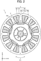
- FIG. 2 is a cross-sectional view schematically illustrating the structure of the motor 1.
- the motor 1 includes the rotor 2, the stator 3, a circuit board 4, a molding resin 5, and bearings 7a and 7b for rotatably retaining the rotor 2.
- the motor 1 is, for example, a permanent magnet synchronous motor such as an interior permanent magnet motor (IPM motor).
- the stator 3 is disposed outside the rotor 2.
- the stator 3 includes a stator core 31, a coil 32, and an insulator 33.
- the stator core 31 is a ring-shaped core including a core back 31a extending in the circumferential direction and a plurality of teeth 31b extending from the core back 31a in the radial direction.
- the stator core 31 is constituted by, for example, a plurality of thin iron magnetic sheets.
- the stator core 31 is constituted by a plurality of electromagnetic steel sheets stacked in the axis direction.
- Each of the electromagnetic steel sheets of the stator core 31 has a thickness of 0.2 mm to 0.5 mm, for example.
- the coil 32 (i.e., winding) is wound around the insulator 33 attached to the stator core 31.
- the coil 32 is insulated by the insulator 33.
- the coil 32 is made of a material containing copper or aluminium, for example.
- the insulator 33 is made of, for example, an insulative resin such as polybutylene terephthalate (PBT), polyphenylene sulfide (PPS), liquid crystal polymer (LCP), or polyethylene terephthalate (PET).
- the resin insulator 33 is, for example, an insulating film having a thickness of 0.035 mm to 0.4 mm.
- the insulator 33 is shaped integrally with the stator core 31. It should be noted that the insulator 33 may be shaped separately from the stator core 31. In this case, after the insulator 33 has been shaped, the insulator 33 is fitted in the stator core 31.
- stator core 31, the coil 32, and the insulator 33 are covered with the molding resin 5.
- the stator core 31, the coil 32, and the insulator 33 may be fixed by a cylindrical shell made of a material containing iron, for example.
- the stator 3 is covered with the cylindrical shell by shrink fitting together with the rotor 2, for example.
- the circuit board 4 is fixed by the molding resin 5 together with the stator 3.
- the circuit board 4 includes a driving device for controlling the motor 1.
- the molding resin 5 unites the circuit board 4 and the stator 3 to each other.
- the molding resin 5 is, for example, a thermosetting resin such as a bulk molding compound (BMC) or an epoxy resin.
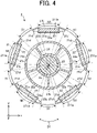
- FIGS. 3 and 4 are cross-sectional views schematically illustrating a structure of the rotor 2.
- N represents a north pole of the rotor 2 (specifically a north pole functioning to the stator 3)
- S represents a south pole of the rotor 2 (specifically a south pole functioning to the stator 3).
- the rotor 2 includes a rotor core 21, a plurality of permanent magnets 22, a shaft 23, and a nonmagnetic member 24.
- the rotor 2 is rotatably disposed inside the stator 3. Specifically, the rotor 2 is disposed inside the stator 3 such that the permanent magnets 22 face the stator 3.
- the rotation axis of the rotor 2 coincides with the axis line Ax.
- An air space is provided between the rotor core 21 and the stator 3.
- the rotor core 21 is constituted by a plurality of cores 210 stacked in the axis direction.
- the rotor core 21 i.e., the plurality of cores 210) is fixed to nonmagnetic member 24.
- the rotor core 21 may be fixed to the shaft 23.
- the shaft 23 is rotatably held by bearings 7a and 7b. When the motor 1 is driven, the rotor core 21 rotates together with the shaft 23.
- the rotor core 21 may be longer than the stator core 31. Accordingly, magnetic flux from the rotor 2 (specifically, the permanent magnets 22) efficiently flows into the stator core 31.
- the rotor core 21 (i.e., the plurality of cores 210) includes a plurality of magnet insertion holes 21a and a shaft insertion hole 21b.
- the rotor core 21 includes a plurality of magnet insertion holes 21a, and at least one permanent magnet 22 is disposed in each of the magnet insertion holes 21a.
- the rotor core 21 is constituted by, for example, a plurality of electromagnetic steel sheets.
- each of the plurality of cores 210 is an electromagnetic steel sheet.
- the plurality of cores 210 may include cores other than electromagnetic steel sheets.
- the rotor core 21 may be constituted by a plurality of iron cores each having a predetermined shape or may be constituted by a mixture of a soft magnetic material and a resin.
- Each of the cores 210 of the rotor core 21 has a thickness of 0.2 mm to 0.5 mm, for example.
- the cores 210 of the rotor core 21 are stacked in the axis direction.
- the plurality of magnet insertion holes 21a are formed at regular intervals in the circumferential direction of the rotor core 21. In this embodiment, five magnet insertion holes 21a are disposed in the rotor core 21. Each of the magnet insertion holes 21a includes a magnet placement portion 21c in which at least one permanent magnet 22 is placed, and two spaces 21d communicating with the magnet placement portion 21c in the longitudinal direction of the permanent magnet 22.
- the shaft insertion hole 21b is disposed in a center portion of the rotor core 21.
- the shaft insertion hole 21b penetrates the rotor core 21 in the axis direction.
- the shaft 23 is disposed in the shaft hole 21b.
- the rotor 2 is a consequent pole rotor.
- the rotor 2 includes a first magnetic pole formed of each permanent magnet 22 and a second magnetic pole that is a pseudo-magnetic pole formed of a part of the rotor core 21 between two adjacent magnet insertion holes 21a. That is, the second magnetic pole is a pseudo-magnetic pole formed of a part of the rotor core 21 adjacent to each magnet insertion hole 21a in the circumferential direction of the rotor core 21.
- the rotor core 2 includes a plurality of first magnetic pole regions N1 and a plurality of second magnetic pole regions S1.
- Each of the first magnetic pole regions N1 is a region including at least a part of the permanent magnet 22 and at least a part of the magnet insertion hole 21a in the xy plane.
- each first magnetic pole region N1 is a region between two lines passing through both ends of a surface 22a of the permanent magnet 22a in contact with an inner wall 211a of the magnet insertion hole 21a facing inward in the radial direction and the rotation center of the rotor in the xy plane.
- Each of the second magnetic pole regions S1 is a region between two lines passing through one end of each of two adjacent magnet insertion holes 21a and the rotation center of the rotor 2 in the xy plane. That is, each second magnetic pole region S1 is a region not including any of the magnet insertion hole 21a and the permanent magnet 22.
- a region between each of the first magnetic pole region N1 and its adjacent second magnetic pole region S1 is an inter-pole region.
- Each of the permanent magnets 22 forms a north pole as the first magnetic pole of the rotor 2.
- a part of the rotor core 21 adjacent to each magnet insertion hole 21a in the circumferential direction of the rotor core 21 forms a south pole as the second magnetic pole that is a pseudo-magnetic pole of the rotor 2.
- each of the first magnetic pole regions N1 functions as the first magnetic pole (magnetic pole serving as a north pole to the stator 3 in this embodiment)
- each of the second magnetic pole regions S1 functions as the second magnetic pole (pseudo-magnetic pole serving as a north pole to the stator 3 in this embodiment).
- each of the first magnetic pole regions N1 functions as a first polarity
- each of the second magnetic pole regions S1 functions as a second polarity different from the first polarity.
- the number of permanent magnets 22 is half of the number n (where n is an even number greater than or equal to four) of magnetic poles of the rotor 2.
- the number n of magnetic poles of the rotor 2 is the sum of the number of magnetic poles functioning as north poles to the stator 3 and the number of magnetic poles functioning as south poles to the stator 3.
- the shaft 23 is fixed to the rotor core 21 with the nonmagnetic member 24, for example.
- the nonmagnetic member 24 is disposed in the shaft insertion hole 21b.
- the nonmagnetic member 24 couples the shaft 23 to the rotor core 21.
- the nonmagnetic member 24 is made of, for example, a non-magnetic material such as austenitic stainless steel, aluminium, a bulk molding compound (BMC), polybutylene terephthalate (PBT), polyphenylene sulfide (PPS), liquid crystal polymer (LCP), or polyethylene terephthalate (PET).
- a non-magnetic material such as austenitic stainless steel, aluminium, a bulk molding compound (BMC), polybutylene terephthalate (PBT), polyphenylene sulfide (PPS), liquid crystal polymer (LCP), or polyethylene terephthalate (PET).
- the nonmagnetic member 24 is, for example, a resin.
- the nonmagnetic member 24 is made of a non-magnetic resin such as a bulk molding compound (BMC), polybutylene terephthalate (PBT), polyphenylene sulfide (PPS), liquid crystal polymer (LCP), polyethylene terephthalate (PET).
- BMC bulk molding compound
- PBT polybutylene terephthalate
- PPS polyphenylene sulfide
- LCP liquid crystal polymer
- PET polyethylene terephthalate
- Each permanent magnet 22 is, for example, a flat-plate permanent magnet.
- Each permanent magnet 22 may be, for example, a rare earth magnet containing neodymium or samarium.
- the permanent magnets 22 may be ferrite magnets containing iron.
- the type of the permanent magnet 22 is not limited to the example of this embodiment, and the permanent magnet 22 may be made of another material.
- the permanent magnets 22 in the magnet insertion holes 21a are magnetized in the radial direction and consequently magnetic flux from the permanent magnets 22 flows into the stator 3.
- FIG. 5 is a diagram illustrating a part of the motor 1 shown in FIG. 2 .
- the intermediate magnet insertion hole of the three magnet insertion holes will be referred to as a "first magnet insertion hole 211”
- the right magnet insertion hole of the three magnet insertion holes will be referred to as a “second magnet insertion hole 212”
- the left magnet insertion hole of the three magnet insertion holes will be referred to as a “third magnet insertion hole 213.” That is, in the xy plane, the second magnet insertion hole 212 and the third magnet insertion hole 213 are adjacent to the first magnet insertion hole 211.
- regions in contact with the permanent magnets 22 are the first magnetic pole regions N1 functioning as first magnetic poles.
- a region between each first magnet insertion hole 211 and its adjacent second magnet insertion hole 212 is the second magnetic pole region S1 functioning as a second magnetic pole that is a pseudo-magnetic pole.
- a tooth facing the first magnet insertion hole 211 will be referred to as a "first tooth 311”
- a tooth on the right side with respect to the first tooth 311 will be referred to as a “second tooth 312”
- a tooth on the left side with respect to the first tooth 311 will be referred to as a “third tooth 313.” That is, in the xy plane, the second tooth 312 and the third tooth 313 are adjacent to the first tooth 311.
- Each tooth 31b has a front end surface facing the rotor core 21.
- the first tooth 311 has a front end surface 311a facing the rotor core 21
- the second tooth 312 has a front end surface 312a facing the rotor core 21
- the third tooth 313 has a front end surface 313a facing the rotor core 21.
- the front end surface 311a of the first tooth 311 will also be referred to as a "first front end surface 311a”
- the front end surface 312a of the second tooth 312 will also be referred to as a "second front end surface 312a”
- the front end surface 313a of the third tooth 313 will also be referred to as a "third front end surface 313a.”
- a direction in which the first tooth 311 extends will also be referred to as a "first radial direction”
- a direction in which the second tooth 312 extends will also be referred to as a “second radial direction”
- a direction in which the third tooth 313 extends will also be referred to as a “third radial direction.”
- a magnetic pole center line C1 indicating the center of the first magnetic pole passes through the center of the permanent magnet 22.
- the magnetic pole center line C1 passing through the magnetic pole center of the first magnetic pole coincides with a first radial direction.
- the first magnet insertion hole 211 faces the first tooth 311.
- One of the two spaces 21d of each magnet insertion hole 21a faces the second tooth 312, and the other space 21d faces the third tooth 313.
- the inner wall 211a of the first magnet insertion hole 211 facing inward in the first radial direction is in contact with the surface 22a of the permanent magnet 22 facing outward in the first radial direction.
- a width M1 is a width of the surface 22a in the longitudinal direction of the permanent magnet 22 in the xy plane.
- the width M1 is a width of the surface 22a in a first direction orthogonal to the magnetic pole center line C1.
- the width W1 is a maximum width of a portion of the inner wall 211a of the first magnet insertion hole 211 in contact with the surface 22a of the permanent magnet 22.
- the width M1 and the width W1 have a relationship of W1 ⁇ M1.
- the width W2 is a minimum width from the first magnet insertion hole 211 to the second magnet insertion hole 212.
- a width T1 is a width of the first front end surface 311a of the first tooth 311 in the first direction orthogonal to the first radial direction in the xy plane. As described above, in FIG. 5 , the first direction is also a direction orthogonal to the magnetic pole center line C1.
- a width T2 is a width from the first front end surface 311a to the second front end surface 312a in the first direction.
- a width T3 is a width from the first front end surface 311a to the third front end surface 313a in the first direction.
- T2 T3.
- the motor 1 satisfies W2 ⁇ W1 ⁇ M1, and T1 ⁇ W1 ⁇ T1 + 2 ⁇ T2.
- a width FB1 is a width of this space 21d in a second direction orthogonal to the second radial direction in the xy plane.
- a width FB2 is a width of a portion of this space 21d facing the second front end surface 312a in a second direction orthogonal to the second radial direction in the xy plane.
- the width FB1 and the width FB2 has a relationship of FB1 > FB2.
- a width FB3 is a width of this space 21d in a third direction orthogonal to the third radial direction in the xy plane.
- a width FB4 is a width of a portion of this space 21d facing the third front end surface 313a in the third direction orthogonal to the tooth radial direction in the xy plane.
- the width FB3 and the width FB4 has a relationship of FB3 > FB4.
- the width FB1 of the space 21d facing the second tooth 312 is equal to the width of the FB3 of the space 21d facing the third tooth 313, and the width FB2 of the space 21d facing the second front end surface 312a is equal to the width FB4 of the space 21d facing the third front end surface 313a.
- FIG. 6 is a diagram illustrating the motor 1 illustrated in FIG. 5 .
- the motor 1 satisfies ⁇ W2 ⁇ ⁇ W1 ⁇ ⁇ M1, and ⁇ T1 ⁇ ⁇ W1 ⁇ ⁇ T1 + 2 ⁇ ⁇ T2.
- angles ⁇ W2, ⁇ W1, ⁇ M1, ⁇ T1, and ⁇ T2 represent angles respectively corresponding to the widths W2, W1, M1, T1, and T2 shown in FIG. 5 .
- the angle ⁇ W2 is an angle at which two lines respectively passing through the two points forming the width W2 (i.e., both ends of the width W2) in the xy plane intersect at the rotation center of the rotor 2. That is, the angle ⁇ W2 is an angle formed by a line passing through one end of the width W2 and the rotation center of the rotor 2 and a line passing through the other end of the width W2 and the rotation center of the rotor 2 in the xy plane.
- the angle ⁇ W1 is an angle at which two lines respectively passing through the two points forming the width W1 in the xy plane intersect at the rotation center of the rotor 2. That is, the angle ⁇ W1 is an angle formed by a line passing through one end of the width W1 and the rotation center of the rotor 2 and a line passing through the other end of the width W1 and the rotation center of the rotor 2 in the xy plane.
- the angle ⁇ M1 is an angle at which two lines respectively passing through the two points forming the width M1 in the xy plane intersect at the rotation center of the rotor 2. That is, the angle ⁇ M1 is an angle formed by a line passing through one end of the width M1 and the rotation center of the rotor 2 and a line passing through the other end of the width M1 and the rotation center of the rotor 2 in the xy plane.
- the angle ⁇ T1 is an angle at which two lines respectively passing through the two points forming the width T1 in the xy plane intersect at the rotation center of the rotor 2. That is, the angle ⁇ T1 is an angle formed by a line passing through one end of the width T1 and the rotation center of the rotor 2 and a line passing through the other end of the width T1 and the rotation center of the rotor 2 in the xy plane.
- the angle ⁇ T2 is an angle at which two lines respectively passing through the two points forming the width T2 in the xy plane intersect at the rotation center of the rotor 2. That is, the angle ⁇ T2 is an angle formed by a line passing through one end of the width T2 and the rotation center of the rotor 2 and a line passing through the other end of the width T2 and the rotation center of the rotor 2 in the xy plane.
- the angle ⁇ FB2 represents an angle corresponding to the width FB2 shown in FIG. 5 .
- the angle ⁇ FB2 is an angle at which two lines respectively passing through the two points forming the width FB2 in the xy plane intersect at the rotation center of the rotor 2. That is, the angle ⁇ FB2 is an angle formed by a line passing through one end of the width FB2 and the rotation center of the rotor 2 and a line passing through the other end of the width FB2 and the rotation center of the rotor 2 in the xy plane.
- FIG. 7 is a cross-sectional view illustrating a motor 1a according to a comparative example.
- a rotor 2a is different from the rotor 2 of the motor 1 according to the present embodiment.
- the rotor 2a of the motor 1a according to the comparative example is not a consequent pole rotor, but a conventional interior permanent magnet (IPM) rotor.
- IPM interior permanent magnet
- permanent magnets 22 functioning as first magnets (e.g., north poles) to a stator 3 and permanent magnets 22 functioning as second magnetic poles (e.g., south poles) to the stator 3 are alternately arranged in the circumferential direction.
- the width M1 of each permanent magnet in the longitudinal direction is limited to L/n at maximum (L: circumference of the rotor core, n: the number of magnetic poles).
- the rotor 2 of the motor 1 according to the present embodiment satisfies W2 ⁇ W1 ⁇ M1.
- the width M1 of each permanent magnet 22 forming the first magnetic pole can be made larger than that in the comparative example.
- efficiency of the rotor 2 can be improved with a smaller number of permanent magnets 22 than the comparative example.
- the motor 1 according to the embodiment satisfies T1 ⁇ W1.
- T1 ⁇ W1 the motor 1 according to the embodiment satisfies T1 ⁇ W1.
- the width W1 is larger than T1 + 2 ⁇ T2
- magnetic flux from the permanent magnet 22 flows into a tooth that is not the target tooth, and thus magnetic flux leakage increases.
- the width W1 is larger than T1 + 2 ⁇ T2
- magnetic flux from the permanent magnet 22 flows into the second tooth 312 and the third tooth 313, and thus magnetic flux leakage increases.
- the motor 1 according to the embodiment satisfies W1 ⁇ T1 + 2 ⁇ T2.
- the motor 1 satisfies W2 ⁇ W1 ⁇ M1, and T1 ⁇ W1 ⁇ T1 + 2 ⁇ T2.
- effective magnetic flux flowing from the permanent magnet 22 to the target tooth can be increased, and thus magnetic flux leakage flowing into a tooth adjacent to the target tooth can be reduced.
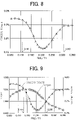
- FIG. 8 is a graph showing a relationship between a cogging torque occurring in the motor 1 and a ratio FB2/T1 of the width FB2 of the space 21d facing the second front end surface 312a to the width T1 of the first front end surface 311a.
- the motor 1 preferably satisfies 0.14 ⁇ FB2/T1 ⁇ 0.34.
- This configuration can reduce a cogging torque in the motor 1. As a result, vibrations and noise caused by a cogging torque in the motor 1 can be reduced.
- FIG. 9 is a graph showing a relationship between a cogging torque and a ratio FB2/T1 of the width FB2 of the space 21d facing the second front end surface 312a to the width T1 of the first front end surface 311a, and a relationship between a torque of the motor 1 and a ratio FB2/T1 of the width FB2 of the space 21d facing the second front end surface 312a to the width T1 of the first front end surface 311a.
- the torque has a maximum value of 1.000.
- the motor 1 preferably satisfies 0.165 ⁇ FB2/T1 ⁇ 0.285.
- This configuration can reduce a cogging torque in the motor 1 while maintaining a maximum torque in the motor 1.
- the motor 1 more preferably satisfies 0.175 ⁇ FB2/T1 ⁇ 0.24.
- This configuration can suppress a decrease of the maximum torque of the motor 1 and can effectively reduce a cogging torque in the motor 1. As a result, a decrease of the maximum torque of the motor 1 can be suppressed, and thus vibrations and noise caused by a cogging torque in the motor 1 can be effectively reduced.
- the motor 1 satisfies ⁇ W2 ⁇ ⁇ M1 ⁇ ⁇ M1, and ⁇ T1 ⁇ ⁇ W1 ⁇ ⁇ T1 + 2 ⁇ ⁇ T2.
- effective magnetic flux flowing from the permanent magnet 22 to the target tooth can be increased, and magnetic flux leakage flowing into the second tooth 312 and the third tooth 313 adjacent to the first tooth 311 that is a target tooth can be reduced.
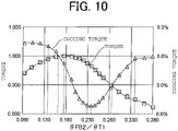
- FIG. 10 is a graph showing a relationship between a cogging torque and a ratio ⁇ FB2/ ⁇ T1 of an angle ⁇ FB2 corresponding to the width FB2 to an angle ⁇ T1 corresponding to the width T1, and a relationship between a torque of the motor 1 and the ratio ⁇ FB2/ ⁇ T1 of the angle ⁇ FB2 corresponding to the width FB2 to the angle ⁇ T1 corresponding to the width T1.
- the torque has a maximum value of 1.000.
- the motor 1 preferably satisfies 0.14 ⁇ ⁇ FB2/ ⁇ T1 ⁇ 0.34. This configuration can reduce a cogging torque in the motor 1. As a result, vibrations and noise caused by a cogging torque in the motor 1 can be reduced.
- the motor 1 preferably satisfies 0.165 ⁇ ⁇ FB2/ ⁇ T1 ⁇ 0.285.
- This configuration can reduce a cogging torque in the motor 1 while maintaining a maximum torque in the motor 1.
- the motor 1 more preferably satisfies 0.175 ⁇ ⁇ FB2/ ⁇ T1 ⁇ 0.24.
- This configuration can suppress a decrease of the maximum torque of the motor 1 and can effectively reduce a cogging torque in the motor 1. As a result, a decrease of the maximum torque of the motor 1 can be suppressed, and thus vibrations and noise caused by a cogging torque in the motor 1 can be effectively reduced.
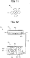
- FIG. 11 is a diagram schematically illustrating a structure of a fan 60 according to a second embodiment.
- the fan 60 includes a blade 61 and a motor 62.
- the fan 60 is also referred to as an air blower.
- the motor 62 is the motor 1 according to the first embodiment.
- the blade 61 is fixed to a shaft of the motor 62.
- the motor 62 drives the blades 61. Specifically, the motor 62 causes the blades 61 to rotate. When the motor 62 is driven, the blades 61 rotate to generate an airflow. In this manner, the fan 60 is capable of sending air.
- the motor 1 described in the first embodiment is applied to the motor 62, and thus, the same advantages as those described in the first embodiment can be obtained. In addition, a decrease in efficiency of the fan 60 can be prevented.
- An air conditioner 50 (also referred to as a refrigeration air conditioning apparatus or a refrigeration cycle apparatus) according to a third embodiment will be described.
- FIG. 12 is a diagram schematically illustrating a configuration the air conditioner 50 according to the third embodiment.
- FIG. 13 is a diagram schematically illustrating main components in an outdoor unit 53 as an air blower of the air conditioner 50.
- the air conditioner 50 includes an indoor unit 51 as an air blower (first air blower), a refrigerant pipe 52, and an outdoor unit 53 as an air blower (second air blower) connected to the indoor unit 51.
- the outdoor unit 53 is connected to the indoor unit 51 through a refrigerant pipe 52.
- the indoor unit 51 includes a motor 51a (e.g., the motor 1 according to the first embodiment), an air blowing unit 51b that supplies air when being driven by the motor 51a, and a housing 51c covering the motor 51a and the air blowing unit 51b.
- the air blowing unit 51b includes, for example, blades 51d that are driven by the motor 51a.
- the blades 51d are fixed to a shaft of the motor 51a, and generate an airflow.
- the outdoor unit 53 includes a motor 53a (e.g., the motor 1 according to the first embodiment), an air blowing unit 53b, a compressor 54, a heat exchanger (not shown), and a housing 53c covering the air blowing unit 53b, the compressor 54, and the heat exchanger.
- a motor 53a e.g., the motor 1 according to the first embodiment
- an air blowing unit 53b e.g., the motor 1 according to the first embodiment
- the air blowing unit 53b supplies air.
- the air blowing unit 53b includes, for example, blades 53d that are driven by the motor 53a.
- the blades 53d are fixed to a shaft of the motor 53a, and generate an airflow.
- the compressor 54 includes a motor 54a (e.g., the motor 1 according to the first embodiment), a compression mechanism 54b (e.g., a refrigerant circuit) that is driven by the motor 54a, and a housing 54c covering the motor 54a and the compression mechanism 54b.
- a motor 54a e.g., the motor 1 according to the first embodiment
- a compression mechanism 54b e.g., a refrigerant circuit
- At least one of the indoor unit 51 or the outdoor unit 53 includes the motor 1 described in the first embodiment. That is, one or both of the indoor unit 51 and the outdoor unit 53 includes the motor 1 described in the first embodiment.
- the motor 1 described in the first embodiment is applied to at least one of the motors 51a or 53a. That is, the motor 1 described in the first embodiment is applicable to one or both of the indoor unit 51 and the outdoor unit 53.
- the motor 1 described in the first embodiment may be applied to the motor 54a of the compressor 54.
- the air conditioner 50 is capable of performing air conditioning such as a cooling operation of sending cold air and a heating operation of sending warm air from the indoor unit 51, for example.
- the motor 51a is a driving source for driving the air blowing unit 51b.
- the air blowing unit 51b is capable of sending conditioned air.
- the motor 53a is fixed to the housing 53c of the outdoor unit 53 by screws 53e, for example.
- the motor 1 described in the first embodiment is applied to at least one of the motors 51a or 53a, and thus, the same advantages as those described in the first embodiment can be obtained. As a result, a decrease in efficiency of the air conditioning apparatus 50 can be prevented.
- the motor 1 according to the first embodiment as a driving source of an air blower (e.g., the indoor unit 51), the same advantages as those described in the first embodiment can be obtained. As a result, a decrease in air blower efficiency can be prevented.
- the blower including the motor 1 according to the first embodiment and the blades (e.g., the blades 51d or 53d) driven by the motor 1 can be used alone as a device for supplying air. This blower is also applicable to equipment other than the air conditioner 50.
- the motor 1 described in the first embodiment can be mounted on equipment including a driving source, such as a ventilator, a household electrical appliance, or a machine tool, as well as the air conditioner 50.
- a driving source such as a ventilator, a household electrical appliance, or a machine tool, as well as the air conditioner 50.
Landscapes
- Engineering & Computer Science (AREA)
- Power Engineering (AREA)
- Chemical & Material Sciences (AREA)
- Combustion & Propulsion (AREA)
- Mechanical Engineering (AREA)
- General Engineering & Computer Science (AREA)
- Permanent Field Magnets Of Synchronous Machinery (AREA)
- Iron Core Of Rotating Electric Machines (AREA)
- Devices For Blowing Cold Air, Devices For Blowing Warm Air, And Means For Preventing Water Condensation In Air Conditioning Units (AREA)
Abstract
Description
- The present disclosure relates to a rotor of a motor.
- A consequent pole rotor including a first magnetic pole portion having a first polarity and a second magnetic pole portion having a second polarity and serving as a pseudo-magnetic pole has been employed in order to reduce the amount of permanent magnets used in a rotor for a motor. In a consequent pole rotor described in
Patent Reference 1, for example, to increase an average magnetic flux density between a stator and a rotor, an occupancy angle of the first magnetic pole portion having a first polarity and an occupancy angle of a second magnetic pole portion having a second polarity and serving as a pseudo-magnetic pole are set. -
Japanese Patent Application Publication No. 2004-201406 - In the technique disclosed in
Patent Reference 1, holes in which permanent magnets are placed communicate with spaces adjacent to the holes. This configuration reduces magnetic flux leakage passing through regions between the holes in which the permanent magnets are placed and the spaces. That is, the configuration reduces magnetic flux leakage flowing from north poles of the permanent magnets into south poles of the permanent magnets. Conventional techniques, however, do not consider magnetic flux leakage other than effective magnetic flux flowing from a consequent pole rotor into target tooth of a stator. That is, magnetic flux leakage flowing into a tooth adjacent to the target tooth is not taken into consideration. Thus, in the conventional techniques, even if a large permanent magnet is disposed in the consequent pole rotor, magnetic flux from the permanent magnet cannot be effectively used. - It is therefore an object of the present disclosure to increase effective magnetic flux flowing from a permanent magnet of a consequent pole rotor into a target tooth of a stator in order to reduce magnetic flux leakage flowing into tooth adjacent to the target tooth.
- A motor according to an aspect of the present disclosure includes:
- a consequent pole rotor including a rotor core, a permanent magnet, a first magnetic pole region, and a second magnetic pole region, the rotor core having a first magnet insertion hole and a second magnet insertion hole adjacent to the first magnet insertion hole, the permanent magnet being disposed in the first magnet insertion hole, the first magnetic pole region functioning as a first magnetic pole, the second magnetic pole region serving as a second magnetic pole, the second magnetic pole being a pseudo-magnetic pole, the pseudo-magnetic pole being formed of a part of the rotor core between the first magnet insertion hole and the second magnet insertion hole; and
- a stator including a core back extending in a circumferential direction, a first tooth extending from the core back in a first radial direction of the consequent pole rotor, and a second tooth adjacent to the first tooth, the stator being disposed outside the consequent pole rotor,
- wherein an inner wall of the first magnet insertion hole facing inward in the first radial direction is in contact with a surface of the permanent magnet, the surface facing outward in the first radial direction, and
- the motor satisfies W2 < W1 < M1, and T1 < W1 < T1 + 2 × T2, where M1 is a width of the surface of the permanent magnet in a longitudinal direction of the permanent magnet in a plane orthogonal to an axis direction of the consequent pole rotor, W1 is a maximum width of a portion of the inner wall of the first magnet insertion hole in the plane, the portion being in contact with the surface of the permanent magnet, W2 is a minimum width from the first magnet insertion hole to the second magnet insertion hole in the plane, T1 is a width of a first front end surface of the first tooth facing the rotor core in a first direction orthogonal to the first radial direction in the plane, and T2 is a width from the first front end surface to a second front end surface of the second tooth facing the rotor core in the first direction.
- A motor according to another aspect of the present disclosure includes: a consequent pole rotor including a rotor core, a permanent magnet, a first magnetic pole region, and a second magnetic pole region, the rotor core having a first magnet insertion hole and a second magnet insertion hole adjacent to the first magnet insertion hole, the permanent magnet being disposed in the first magnet insertion hole, the first magnetic pole region functioning as a first magnetic pole, the second magnetic pole region serving as a second magnetic pole, the second magnetic pole being a pseudo-magnetic pole, the pseudo-magnetic pole being formed of a part of the rotor core between the first magnet insertion hole and the second magnet insertion hole; and
- a stator including a core back extending in a circumferential direction, a first tooth extending from the core back in a first radial direction of the consequent pole rotor, and a second tooth adjacent to the first tooth, the stator being disposed outside the consequent pole rotor,
- wherein an inner wall of the first magnet insertion hole facing inward in the first radial direction is in contact with a surface of the permanent magnet, the surface facing outward in the first radial direction,
- the motor satisfies θW2 < θW1 < θM1, and θT1 < θW1 < θT1 + 2 × θT2, where M1 is a width of the surface of the permanent magnet in a longitudinal direction of the permanent magnet in a plane orthogonal to an axis direction of the consequent pole rotor, W1 is a maximum width of a portion of the inner wall of the first magnet insertion hole in the plane, the portion being in contact with the surface of the permanent magnet, W2 is a minimum width from the first magnet insertion hole to the second magnet insertion hole in the plane, T1 is a width of a first front end surface of the first tooth facing the rotor core in a first direction orthogonal to the first radial direction in the plane, T2 is a width from the first front end surface to a second front end surface of the second tooth facing the rotor core in the first direction, θW1 is an angle at which two lines respectively passing through two points forming the maximum width W1 intersect at a rotation center of the consequent pole rotor in the plane, θW2 is an angle at which two lines respectively passing through two points forming the minimum width W2 intersect at the rotation center in the plane, θM1 is an angle at which two lines respectively passing through two points forming the width M1 intersect at the rotation center, θT1 is an angle at which two lines respectively passing through two points forming the width T1 intersect at the rotation center in the plane, and θT2 is an angle at which two lines respectively passing through two points forming the width T2 intersect at the rotation center in the plane.
- A fan according to another aspect of the present disclosure includes: a blade; and the motor configured to drive the blade.
- An air conditioner according to another aspect of the present disclosure includes: an indoor unit; and an outdoor unit connected to the indoor unit, wherein one or both of the indoor unit and the outdoor unit include the motor.
- According to the present disclosure, effective magnetic flux flowing from the permanent magnet of the consequent pole rotor into a target tooth of the stator is increased, and magnetic flux leakage flowing into a tooth adjacent to the target tooth can be reduced.
-
-
FIG. 1 is a partial cross-sectional view schematically illustrating a structure of a motor according to a first embodiment. -
FIG. 2 is a cross-sectional view schematically illustrating the structure of the motor. -
FIG. 3 is a cross-sectional view schematically illustrating a structure of a rotor. -
FIG. 4 is a cross-sectional view schematically illustrating the structure of the rotor. -
FIG. 5 is a diagram illustrating a part of the motor shown inFIG. 2 . -
FIG. 6 is a diagram illustrating the motor shown inFIG. 5 . -
FIG. 7 is a cross-sectional view illustrating a motor according to a comparative example. -
FIG. 8 is a graph showing a relationship between a cogging torque occurring in a motor and a ratio of a width of a space facing a second front end surface to a width of a first front end surface. -
FIG. 9 is a graph showing a relationship between the cogging torque and the ratio of the width of the space facing the second front end surface to the width of the first front end surface, and a relationship between a torque of the motor and the ratio of the width of the space facing the second front end surface to the width of the first front end surface. -
FIG. 10 is a graph showing a relationship between the cogging torque and a ratio θFB2/θT1 of an angle θFB2 corresponding to a width FB2 to an angle θT1 corresponding to a width T1, and a relationship between a torque of amotor 1 and the ratio θFB2/θT1 of the angle θFB2 corresponding to the width FB2 to the angle θT1 corresponding to the width T1. -
FIG. 11 is a diagram schematically illustrating a structure of a fan according to a second embodiment. -
FIG. 12 is a diagram schematically illustrating a configuration of an air conditioner according to a third embodiment. -
FIG. 13 is a diagram schematically illustrating main components in an outdoor unit as an air blower of the air conditioner. - A
motor 1 according to a first embodiment will be described. - In an xyz orthogonal coordinate system shown in each drawing, a z-axis direction (z axis) represents a direction parallel to an axis Ax of the
motor 1, an x-axis direction (x axis) represents a direction orthogonal to the z-axis direction (z axis), and a y-axis direction (y axis) represents a direction orthogonal to both the z-axis direction and the x-axis direction. The axis Ax is a rotation center of arotor 2, that is, a rotation axis of therotor 2. The direction parallel to the axis Ax will also be referred to as an "axis direction of therotor 2" or simply an "axis direction." The radial direction refers to a direction of a radius of therotor 2 or astator 3, and is a direction orthogonal to the axis Ax. An xy plane is a plane orthogonal to the axis direction. An arrow D1 represents a circumferential direction about the axis Ax. A circumferential direction of therotor 2 or thestator 3 will also be simply referred to as a "circumferential direction." -
FIG. 1 is a partial cross-sectional view schematically illustrating a structure of themotor 1 according to the first embodiment. -
FIG. 2 is a cross-sectional view schematically illustrating the structure of themotor 1. - The
motor 1 includes therotor 2, thestator 3, acircuit board 4, amolding resin 5, andbearings rotor 2. Themotor 1 is, for example, a permanent magnet synchronous motor such as an interior permanent magnet motor (IPM motor). - The
stator 3 is disposed outside therotor 2. Thestator 3 includes astator core 31, acoil 32, and aninsulator 33. Thestator core 31 is a ring-shaped core including acore back 31a extending in the circumferential direction and a plurality ofteeth 31b extending from thecore back 31a in the radial direction. - The
stator core 31 is constituted by, for example, a plurality of thin iron magnetic sheets. In this embodiment, thestator core 31 is constituted by a plurality of electromagnetic steel sheets stacked in the axis direction. Each of the electromagnetic steel sheets of thestator core 31 has a thickness of 0.2 mm to 0.5 mm, for example. - The coil 32 (i.e., winding) is wound around the
insulator 33 attached to thestator core 31. Thecoil 32 is insulated by theinsulator 33. Thecoil 32 is made of a material containing copper or aluminium, for example. - The
insulator 33 is made of, for example, an insulative resin such as polybutylene terephthalate (PBT), polyphenylene sulfide (PPS), liquid crystal polymer (LCP), or polyethylene terephthalate (PET). Theresin insulator 33 is, for example, an insulating film having a thickness of 0.035 mm to 0.4 mm. - For example, the
insulator 33 is shaped integrally with thestator core 31. It should be noted that theinsulator 33 may be shaped separately from thestator core 31. In this case, after theinsulator 33 has been shaped, theinsulator 33 is fitted in thestator core 31. - In this embodiment, the
stator core 31, thecoil 32, and theinsulator 33 are covered with themolding resin 5. Thestator core 31, thecoil 32, and theinsulator 33 may be fixed by a cylindrical shell made of a material containing iron, for example. In this case, thestator 3 is covered with the cylindrical shell by shrink fitting together with therotor 2, for example. - The
circuit board 4 is fixed by themolding resin 5 together with thestator 3. Thecircuit board 4 includes a driving device for controlling themotor 1. - The
molding resin 5 unites thecircuit board 4 and thestator 3 to each other. Themolding resin 5 is, for example, a thermosetting resin such as a bulk molding compound (BMC) or an epoxy resin. -
FIGS. 3 and4 are cross-sectional views schematically illustrating a structure of therotor 2. InFIG. 3 , "N" represents a north pole of the rotor 2 (specifically a north pole functioning to the stator 3), and "S" represents a south pole of the rotor 2 (specifically a south pole functioning to the stator 3). - The
rotor 2 includes arotor core 21, a plurality ofpermanent magnets 22, ashaft 23, and anonmagnetic member 24. Therotor 2 is rotatably disposed inside thestator 3. Specifically, therotor 2 is disposed inside thestator 3 such that thepermanent magnets 22 face thestator 3. The rotation axis of therotor 2 coincides with the axis line Ax. An air space is provided between therotor core 21 and thestator 3. - The
rotor core 21 is constituted by a plurality ofcores 210 stacked in the axis direction. The rotor core 21 (i.e., the plurality of cores 210) is fixed tononmagnetic member 24. Therotor core 21 may be fixed to theshaft 23. Theshaft 23 is rotatably held bybearings motor 1 is driven, therotor core 21 rotates together with theshaft 23. - In the axis direction, the
rotor core 21 may be longer than thestator core 31. Accordingly, magnetic flux from the rotor 2 (specifically, the permanent magnets 22) efficiently flows into thestator core 31. - The rotor core 21 (i.e., the plurality of cores 210) includes a plurality of
magnet insertion holes 21a and ashaft insertion hole 21b. - In this embodiment, the
rotor core 21 includes a plurality ofmagnet insertion holes 21a, and at least onepermanent magnet 22 is disposed in each of themagnet insertion holes 21a. - The
rotor core 21 is constituted by, for example, a plurality of electromagnetic steel sheets. In this case, each of the plurality ofcores 210 is an electromagnetic steel sheet. The plurality ofcores 210 may include cores other than electromagnetic steel sheets. For example, therotor core 21 may be constituted by a plurality of iron cores each having a predetermined shape or may be constituted by a mixture of a soft magnetic material and a resin. - Each of the
cores 210 of therotor core 21 has a thickness of 0.2 mm to 0.5 mm, for example. Thecores 210 of therotor core 21 are stacked in the axis direction. - The plurality of
magnet insertion holes 21a are formed at regular intervals in the circumferential direction of therotor core 21. In this embodiment, fivemagnet insertion holes 21a are disposed in therotor core 21. Each of themagnet insertion holes 21a includes amagnet placement portion 21c in which at least onepermanent magnet 22 is placed, and twospaces 21d communicating with themagnet placement portion 21c in the longitudinal direction of thepermanent magnet 22. - The
shaft insertion hole 21b is disposed in a center portion of therotor core 21. Theshaft insertion hole 21b penetrates therotor core 21 in the axis direction. Theshaft 23 is disposed in theshaft hole 21b. - The
rotor 2 is a consequent pole rotor. Specifically, therotor 2 includes a first magnetic pole formed of eachpermanent magnet 22 and a second magnetic pole that is a pseudo-magnetic pole formed of a part of therotor core 21 between two adjacentmagnet insertion holes 21a. That is, the second magnetic pole is a pseudo-magnetic pole formed of a part of therotor core 21 adjacent to eachmagnet insertion hole 21a in the circumferential direction of therotor core 21. - As illustrated in
FIG. 4 , therotor core 2 includes a plurality of first magnetic pole regions N1 and a plurality of second magnetic pole regions S1. Each of the first magnetic pole regions N1 is a region including at least a part of thepermanent magnet 22 and at least a part of themagnet insertion hole 21a in the xy plane. Specifically, each first magnetic pole region N1 is a region between two lines passing through both ends of asurface 22a of thepermanent magnet 22a in contact with aninner wall 211a of themagnet insertion hole 21a facing inward in the radial direction and the rotation center of the rotor in the xy plane. Each of the second magnetic pole regions S1 is a region between two lines passing through one end of each of two adjacentmagnet insertion holes 21a and the rotation center of therotor 2 in the xy plane. That is, each second magnetic pole region S1 is a region not including any of themagnet insertion hole 21a and thepermanent magnet 22. - A region between each of the first magnetic pole region N1 and its adjacent second magnetic pole region S1 is an inter-pole region.
- Each of the
permanent magnets 22 forms a north pole as the first magnetic pole of therotor 2. A part of therotor core 21 adjacent to eachmagnet insertion hole 21a in the circumferential direction of therotor core 21 forms a south pole as the second magnetic pole that is a pseudo-magnetic pole of therotor 2. In this case, each of the first magnetic pole regions N1 functions as the first magnetic pole (magnetic pole serving as a north pole to thestator 3 in this embodiment), and each of the second magnetic pole regions S1 functions as the second magnetic pole (pseudo-magnetic pole serving as a north pole to thestator 3 in this embodiment). In other words, each of the first magnetic pole regions N1 functions as a first polarity, and each of the second magnetic pole regions S1 functions as a second polarity different from the first polarity. - The number of
permanent magnets 22 is half of the number n (where n is an even number greater than or equal to four) of magnetic poles of therotor 2. The number n of magnetic poles of therotor 2 is the sum of the number of magnetic poles functioning as north poles to thestator 3 and the number of magnetic poles functioning as south poles to thestator 3. The north poles and the south poles of therotor 2 are alternately arranged in the circumferential direction of therotor 2. In this embodiment, n = 10. - The
shaft 23 is fixed to therotor core 21 with thenonmagnetic member 24, for example. Thenonmagnetic member 24 is disposed in theshaft insertion hole 21b. Thenonmagnetic member 24 couples theshaft 23 to therotor core 21. - The
nonmagnetic member 24 is made of, for example, a non-magnetic material such as austenitic stainless steel, aluminium, a bulk molding compound (BMC), polybutylene terephthalate (PBT), polyphenylene sulfide (PPS), liquid crystal polymer (LCP), or polyethylene terephthalate (PET). - The
nonmagnetic member 24 is, for example, a resin. In this case, thenonmagnetic member 24 is made of a non-magnetic resin such as a bulk molding compound (BMC), polybutylene terephthalate (PBT), polyphenylene sulfide (PPS), liquid crystal polymer (LCP), polyethylene terephthalate (PET). - Each
permanent magnet 22 is, for example, a flat-plate permanent magnet. Eachpermanent magnet 22 may be, for example, a rare earth magnet containing neodymium or samarium. Thepermanent magnets 22 may be ferrite magnets containing iron. The type of thepermanent magnet 22 is not limited to the example of this embodiment, and thepermanent magnet 22 may be made of another material. - The
permanent magnets 22 in themagnet insertion holes 21a are magnetized in the radial direction and consequently magnetic flux from thepermanent magnets 22 flows into thestator 3. -
FIG. 5 is a diagram illustrating a part of themotor 1 shown inFIG. 2 . - In
FIG. 5 , the intermediate magnet insertion hole of the three magnet insertion holes will be referred to as a "firstmagnet insertion hole 211," the right magnet insertion hole of the three magnet insertion holes will be referred to as a "secondmagnet insertion hole 212," and the left magnet insertion hole of the three magnet insertion holes will be referred to as a "thirdmagnet insertion hole 213." That is, in the xy plane, the secondmagnet insertion hole 212 and the thirdmagnet insertion hole 213 are adjacent to the firstmagnet insertion hole 211. - As described with reference to
FIG. 4 , in therotor core 21 illustrated inFIG. 5 , regions in contact with thepermanent magnets 22 are the first magnetic pole regions N1 functioning as first magnetic poles. In therotor core 21 illustrated inFIG. 5 , a region between each firstmagnet insertion hole 211 and its adjacent secondmagnet insertion hole 212 is the second magnetic pole region S1 functioning as a second magnetic pole that is a pseudo-magnetic pole. - In
FIG. 5 , a tooth facing the firstmagnet insertion hole 211 will be referred to as a "first tooth 311," a tooth on the right side with respect to thefirst tooth 311 will be referred to as a "second tooth 312," and a tooth on the left side with respect to thefirst tooth 311 will be referred to as a "third tooth 313." That is, in the xy plane, thesecond tooth 312 and thethird tooth 313 are adjacent to thefirst tooth 311. - Each
tooth 31b has a front end surface facing therotor core 21. In the example illustrated inFIG. 5 , thefirst tooth 311 has afront end surface 311a facing therotor core 21, thesecond tooth 312 has afront end surface 312a facing therotor core 21, and thethird tooth 313 has afront end surface 313a facing therotor core 21. Thefront end surface 311a of thefirst tooth 311 will also be referred to as a "firstfront end surface 311a," thefront end surface 312a of thesecond tooth 312 will also be referred to as a "secondfront end surface 312a," and thefront end surface 313a of thethird tooth 313 will also be referred to as a "thirdfront end surface 313a." - In the xy plane illustrated in
FIG. 5 , a direction in which thefirst tooth 311 extends will also be referred to as a "first radial direction," a direction in which thesecond tooth 312 extends will also be referred to as a "second radial direction," and a direction in which thethird tooth 313 extends will also be referred to as a "third radial direction." - In the xy plane, a magnetic pole center line C1 indicating the center of the first magnetic pole passes through the center of the
permanent magnet 22. As illustrated inFIG. 5 , in the xy plane, the magnetic pole center line C1 passing through the magnetic pole center of the first magnetic pole coincides with a first radial direction. In this case, the firstmagnet insertion hole 211 faces thefirst tooth 311. - One of the two
spaces 21d of eachmagnet insertion hole 21a faces thesecond tooth 312, and theother space 21d faces thethird tooth 313. - The
inner wall 211a of the firstmagnet insertion hole 211 facing inward in the first radial direction is in contact with thesurface 22a of thepermanent magnet 22 facing outward in the first radial direction. - A width M1 is a width of the
surface 22a in the longitudinal direction of thepermanent magnet 22 in the xy plane. In the example illustrated inFIG. 5 , the width M1 is a width of thesurface 22a in a first direction orthogonal to the magnetic pole center line C1. - In the xy plane, the width W1 is a maximum width of a portion of the
inner wall 211a of the firstmagnet insertion hole 211 in contact with thesurface 22a of thepermanent magnet 22. In this embodiment, the width M1 and the width W1 have a relationship of W1 < M1. - In the xy plane, the width W2 is a minimum width from the first
magnet insertion hole 211 to the secondmagnet insertion hole 212. - A width T1 is a width of the first
front end surface 311a of thefirst tooth 311 in the first direction orthogonal to the first radial direction in the xy plane. As described above, inFIG. 5 , the first direction is also a direction orthogonal to the magnetic pole center line C1. - A width T2 is a width from the first
front end surface 311a to the secondfront end surface 312a in the first direction. A width T3 is a width from the firstfront end surface 311a to the thirdfront end surface 313a in the first direction. In this embodiment, T2 = T3. A width from the secondfront end surface 312a to the thirdfront end surface 313a in the first direction is T2 + T1 + T3 = T1 + 2 × T2. - In the example illustrated in
FIG. 5 , themotor 1 satisfies W2 < W1 < M1, and T1 < W1 < T1 + 2 × T2. - With respect to the
space 21d facing thesecond tooth 312, a width FB1 is a width of thisspace 21d in a second direction orthogonal to the second radial direction in the xy plane. With respect to thespace 21d facing thesecond tooth 312, a width FB2 is a width of a portion of thisspace 21d facing the secondfront end surface 312a in a second direction orthogonal to the second radial direction in the xy plane. In the example illustrated inFIG. 5 , with respect to thespace 21d facing thesecond tooth 312, the width FB1 and the width FB2 has a relationship of FB1 > FB2. - Similarly, with respect to the
space 21d facing thethird tooth 313, a width FB3 is a width of thisspace 21d in a third direction orthogonal to the third radial direction in the xy plane. With respect to thespace 21d facing thethird tooth 313, a width FB4 is a width of a portion of thisspace 21d facing the thirdfront end surface 313a in the third direction orthogonal to the tooth radial direction in the xy plane. In the example illustrated inFIG. 5 , with respect to thespace 21d facing thethird tooth 313, the width FB3 and the width FB4 has a relationship of FB3 > FB4. - In this embodiment, the width FB1 of the
space 21d facing thesecond tooth 312 is equal to the width of the FB3 of thespace 21d facing thethird tooth 313, and the width FB2 of thespace 21d facing the secondfront end surface 312a is equal to the width FB4 of thespace 21d facing the thirdfront end surface 313a. -
FIG. 6 is a diagram illustrating themotor 1 illustrated inFIG. 5 . - In the example illustrated in
FIG. 6 , themotor 1 satisfies θW2 < θW1 < θM1, and θT1 < θW1 < θT1 + 2 × θT2. - The angles θW2, θW1, θM1, θT1, and θT2 represent angles respectively corresponding to the widths W2, W1, M1, T1, and T2 shown in
FIG. 5 . - Specifically, the angle θW2 is an angle at which two lines respectively passing through the two points forming the width W2 (i.e., both ends of the width W2) in the xy plane intersect at the rotation center of the
rotor 2. That is, the angle θW2 is an angle formed by a line passing through one end of the width W2 and the rotation center of therotor 2 and a line passing through the other end of the width W2 and the rotation center of therotor 2 in the xy plane. - The angle θW1 is an angle at which two lines respectively passing through the two points forming the width W1 in the xy plane intersect at the rotation center of the
rotor 2. That is, the angle θW1 is an angle formed by a line passing through one end of the width W1 and the rotation center of therotor 2 and a line passing through the other end of the width W1 and the rotation center of therotor 2 in the xy plane. - The angle θM1 is an angle at which two lines respectively passing through the two points forming the width M1 in the xy plane intersect at the rotation center of the
rotor 2. That is, the angle θM1 is an angle formed by a line passing through one end of the width M1 and the rotation center of therotor 2 and a line passing through the other end of the width M1 and the rotation center of therotor 2 in the xy plane. - The angle θT1 is an angle at which two lines respectively passing through the two points forming the width T1 in the xy plane intersect at the rotation center of the
rotor 2. That is, the angle θT1 is an angle formed by a line passing through one end of the width T1 and the rotation center of therotor 2 and a line passing through the other end of the width T1 and the rotation center of therotor 2 in the xy plane. - The angle θT2 is an angle at which two lines respectively passing through the two points forming the width T2 in the xy plane intersect at the rotation center of the
rotor 2. That is, the angle θT2 is an angle formed by a line passing through one end of the width T2 and the rotation center of therotor 2 and a line passing through the other end of the width T2 and the rotation center of therotor 2 in the xy plane. - Similarly, the angle θFB2 represents an angle corresponding to the width FB2 shown in
FIG. 5 . Specifically, the angle θFB2 is an angle at which two lines respectively passing through the two points forming the width FB2 in the xy plane intersect at the rotation center of therotor 2. That is, the angle θFB2 is an angle formed by a line passing through one end of the width FB2 and the rotation center of therotor 2 and a line passing through the other end of the width FB2 and the rotation center of therotor 2 in the xy plane. -
FIG. 7 is a cross-sectional view illustrating amotor 1a according to a comparative example. - In the
motor 1a according to the comparative example, arotor 2a is different from therotor 2 of themotor 1 according to the present embodiment. Specifically, therotor 2a of themotor 1a according to the comparative example is not a consequent pole rotor, but a conventional interior permanent magnet (IPM) rotor. Specifically, in therotor 2a of themotor 1a according to the comparative example,permanent magnets 22 functioning as first magnets (e.g., north poles) to astator 3 andpermanent magnets 22 functioning as second magnetic poles (e.g., south poles) to thestator 3 are alternately arranged in the circumferential direction. - In general, in an IPM rotor, as a width M1 of each permanent magnet in a longitudinal direction increases, a magnetic force of the permanent magnet increases, and thus an output of the rotor increases. However, in a conventional motor that is not a consequent pole rotor, the width M1 of each permanent magnet in the longitudinal direction, specifically the width of each permanent magnet in the circumferential direction, is limited to L/n at maximum (L: circumference of the rotor core, n: the number of magnetic poles).
- On the other hand, as shown in
FIG. 5 , therotor 2 of themotor 1 according to the present embodiment satisfies W2 < W1 < M1. Thus, in therotor 2 of themotor 1 according to the present embodiment, the width M1 of eachpermanent magnet 22 forming the first magnetic pole can be made larger than that in the comparative example. As a result, efficiency of therotor 2 can be improved with a smaller number ofpermanent magnets 22 than the comparative example. - As shown in
FIG. 5 , themotor 1 according to the embodiment satisfies T1 < W1. Thus, in the example shown inFIG. 5 , it is possible to increase effective magnetic flux flowing from thepermanent magnet 22 to thefirst tooth 311 that is a target tooth. - In a case where the width W1 is larger than T1 + 2 × T2, magnetic flux from the
permanent magnet 22 flows into a tooth that is not the target tooth, and thus magnetic flux leakage increases. In a case where the width W1 is larger than T1 + 2 × T2, inFIG. 5 , for example, magnetic flux from thepermanent magnet 22 flows into thesecond tooth 312 and thethird tooth 313, and thus magnetic flux leakage increases. As shown inFIG. 5 , themotor 1 according to the embodiment satisfies W1 < T1 + 2 × T2. Thus, in the example shown inFIG. 5 , it is possible to reduce magnetic flux leakage flowing into thesecond tooth 312 and thethird tooth 313 adjacent to thefirst tooth 311 that is a target tooth. - The
motor 1 according to the embodiment satisfies W2 < W1 < M1, and T1 < W1 < T1 + 2 × T2. Thus, effective magnetic flux flowing from thepermanent magnet 22 to the target tooth can be increased, and thus magnetic flux leakage flowing into a tooth adjacent to the target tooth can be reduced. - When the width FB1 and the width FB2 satisfy FB1 > FB2, magnetic flux leakage flowing from the
permanent magnet 22 disposed in the firstmagnet insertion hole 211 into thesecond tooth 312 can be reduced. Thus, effective magnetic flux flowing from thepermanent magnet 22 into the target tooth can be increased, and magnetic flux leakage flowing into a tooth adjacent to the target tooth can be reduced. -
FIG. 8 is a graph showing a relationship between a cogging torque occurring in themotor 1 and a ratio FB2/T1 of the width FB2 of thespace 21d facing the secondfront end surface 312a to the width T1 of the firstfront end surface 311a. - As shown in
FIG. 8 , themotor 1 preferably satisfies 0.14 < FB2/T1 < 0.34. This configuration can reduce a cogging torque in themotor 1. As a result, vibrations and noise caused by a cogging torque in themotor 1 can be reduced. -
FIG. 9 is a graph showing a relationship between a cogging torque and a ratio FB2/T1 of the width FB2 of thespace 21d facing the secondfront end surface 312a to the width T1 of the firstfront end surface 311a, and a relationship between a torque of themotor 1 and a ratio FB2/T1 of the width FB2 of thespace 21d facing the secondfront end surface 312a to the width T1 of the firstfront end surface 311a. InFIG. 9 , it is assumed that the torque has a maximum value of 1.000. - As shown in
FIG. 9 , themotor 1 preferably satisfies 0.165 < FB2/T1 < 0.285. This configuration can reduce a cogging torque in themotor 1 while maintaining a maximum torque in themotor 1. As a result, it is possible to reduce vibrations and noise caused by a cogging torque in themotor 1 while maintaining a maximum torque in themotor 1. - As shown in
FIG. 9 , themotor 1 more preferably satisfies 0.175 < FB2/T1 < 0.24. This configuration can suppress a decrease of the maximum torque of themotor 1 and can effectively reduce a cogging torque in themotor 1. As a result, a decrease of the maximum torque of themotor 1 can be suppressed, and thus vibrations and noise caused by a cogging torque in themotor 1 can be effectively reduced. - As shown in
FIG. 6 , themotor 1 according to the embodiment satisfies θW2 < θM1 < θM1, and θT1 < θW1 < θT1 + 2 × θT2. Thus, in the example shown inFIG. 6 , effective magnetic flux flowing from thepermanent magnet 22 to the target tooth can be increased, and magnetic flux leakage flowing into thesecond tooth 312 and thethird tooth 313 adjacent to thefirst tooth 311 that is a target tooth can be reduced. -
FIG. 10 is a graph showing a relationship between a cogging torque and a ratio θFB2/θT1 of an angle θFB2 corresponding to the width FB2 to an angle θT1 corresponding to the width T1, and a relationship between a torque of themotor 1 and the ratio θFB2/θT1 of the angle θFB2 corresponding to the width FB2 to the angle θT1 corresponding to the width T1. InFIG. 10 , it is assumed that the torque has a maximum value of 1.000. - As shown in
FIG. 10 , themotor 1 preferably satisfies 0.14 < θFB2/θT1 < 0.34. This configuration can reduce a cogging torque in themotor 1. As a result, vibrations and noise caused by a cogging torque in themotor 1 can be reduced. - As shown in
FIG. 10 , themotor 1 preferably satisfies 0.165 < θFB2/θT1 < 0.285. This configuration can reduce a cogging torque in themotor 1 while maintaining a maximum torque in themotor 1. As a result, it is possible to reduce vibrations and noise caused by a cogging torque in themotor 1 while maintaining a maximum torque in themotor 1. - As shown in
FIG. 10 , themotor 1 more preferably satisfies 0.175 < θFB2/θT1 < 0.24. This configuration can suppress a decrease of the maximum torque of themotor 1 and can effectively reduce a cogging torque in themotor 1. As a result, a decrease of the maximum torque of themotor 1 can be suppressed, and thus vibrations and noise caused by a cogging torque in themotor 1 can be effectively reduced. -
FIG. 11 is a diagram schematically illustrating a structure of afan 60 according to a second embodiment. - The
fan 60 includes ablade 61 and amotor 62. Thefan 60 is also referred to as an air blower. Themotor 62 is themotor 1 according to the first embodiment. Theblade 61 is fixed to a shaft of themotor 62. Themotor 62 drives theblades 61. Specifically, themotor 62 causes theblades 61 to rotate. When themotor 62 is driven, theblades 61 rotate to generate an airflow. In this manner, thefan 60 is capable of sending air. - In the
fan 60 according to the second embodiment, themotor 1 described in the first embodiment is applied to themotor 62, and thus, the same advantages as those described in the first embodiment can be obtained. In addition, a decrease in efficiency of thefan 60 can be prevented. - An air conditioner 50 (also referred to as a refrigeration air conditioning apparatus or a refrigeration cycle apparatus) according to a third embodiment will be described.
-
FIG. 12 is a diagram schematically illustrating a configuration theair conditioner 50 according to the third embodiment. -
FIG. 13 is a diagram schematically illustrating main components in anoutdoor unit 53 as an air blower of theair conditioner 50. - The
air conditioner 50 according to the third embodiment includes anindoor unit 51 as an air blower (first air blower), arefrigerant pipe 52, and anoutdoor unit 53 as an air blower (second air blower) connected to theindoor unit 51. For example, theoutdoor unit 53 is connected to theindoor unit 51 through arefrigerant pipe 52. - The
indoor unit 51 includes amotor 51a (e.g., themotor 1 according to the first embodiment), anair blowing unit 51b that supplies air when being driven by themotor 51a, and ahousing 51c covering themotor 51a and theair blowing unit 51b. Theair blowing unit 51b includes, for example,blades 51d that are driven by themotor 51a. For example, theblades 51d are fixed to a shaft of themotor 51a, and generate an airflow. - The
outdoor unit 53 includes amotor 53a (e.g., themotor 1 according to the first embodiment), anair blowing unit 53b, acompressor 54, a heat exchanger (not shown), and ahousing 53c covering theair blowing unit 53b, thecompressor 54, and the heat exchanger. When theair blowing unit 53b is driven by themotor 53a, theair blowing unit 53b supplies air. Theair blowing unit 53b includes, for example,blades 53d that are driven by themotor 53a. For example, theblades 53d are fixed to a shaft of themotor 53a, and generate an airflow. Thecompressor 54 includes amotor 54a (e.g., themotor 1 according to the first embodiment), acompression mechanism 54b (e.g., a refrigerant circuit) that is driven by themotor 54a, and ahousing 54c covering themotor 54a and thecompression mechanism 54b. - In the
air conditioner 50, at least one of theindoor unit 51 or theoutdoor unit 53 includes themotor 1 described in the first embodiment. That is, one or both of theindoor unit 51 and theoutdoor unit 53 includes themotor 1 described in the first embodiment. Specifically, as a driving source of an air blowing unit, themotor 1 described in the first embodiment is applied to at least one of themotors motor 1 described in the first embodiment is applicable to one or both of theindoor unit 51 and theoutdoor unit 53. Themotor 1 described in the first embodiment may be applied to themotor 54a of thecompressor 54. - The
air conditioner 50 is capable of performing air conditioning such as a cooling operation of sending cold air and a heating operation of sending warm air from theindoor unit 51, for example. In theindoor unit 51, themotor 51a is a driving source for driving theair blowing unit 51b. Theair blowing unit 51b is capable of sending conditioned air. - As illustrated in
FIG. 13 , in theoutdoor unit 53, themotor 53a is fixed to thehousing 53c of theoutdoor unit 53 byscrews 53e, for example. - In the
air conditioner 50 according to the third embodiment, themotor 1 described in the first embodiment is applied to at least one of themotors air conditioning apparatus 50 can be prevented. - Furthermore, with the use of the
motor 1 according to the first embodiment as a driving source of an air blower (e.g., the indoor unit 51), the same advantages as those described in the first embodiment can be obtained. As a result, a decrease in air blower efficiency can be prevented. The blower including themotor 1 according to the first embodiment and the blades (e.g., theblades motor 1 can be used alone as a device for supplying air. This blower is also applicable to equipment other than theair conditioner 50. - Furthermore, in the case of using the
motor 1 according to the first embodiment as a driving source of theindoor unit 54, the same advantages as those described in the first embodiment can be obtained. As a result, a decrease in efficiency of thecompressor 54 can be prevented. - The
motor 1 described in the first embodiment can be mounted on equipment including a driving source, such as a ventilator, a household electrical appliance, or a machine tool, as well as theair conditioner 50. - Features of the embodiments described above can be combined as appropriate.
- 1, 51a, 53a, 62 motor, 2 rotor, 3 stator, 21 rotor core, 21a magnet insertion hole, 21b shaft insertion hole, 22 permanent magnet, 24 nonmagnetic member, 50 air conditioner, 51 indoor unit, 53 outdoor unit, 60 fan, 61 blade, 210 core, 311 first tooth, 312 second tooth, 313 third tooth, 311a, 312a, 313a front end surface, N1 first magnetic pole region, S1 second magnetic pole region.
Claims (11)
- A motor comprising:a consequent pole rotor including a rotor core, a permanent magnet, a first magnetic pole region, and a second magnetic pole region, the rotor core having a first magnet insertion hole and a second magnet insertion hole adjacent to the first magnet insertion hole, the permanent magnet being disposed in the first magnet insertion hole, the first magnetic pole region functioning as a first magnetic pole, the second magnetic pole region serving as a second magnetic pole, the second magnetic pole being a pseudo-magnetic pole, the pseudo-magnetic pole being formed of a part of the rotor core between the first magnet insertion hole and the second magnet insertion hole; anda stator including a core back extending in a circumferential direction, a first tooth extending from the core back in a first radial direction of the consequent pole rotor, and a second tooth adjacent to the first tooth, the stator being disposed outside the consequent pole rotor, whereinan inner wall of the first magnet insertion hole facing inward in the first radial direction is in contact with a surface of the permanent magnet, the surface facing outward in the first radial direction, andthe motor satisfies W2 < W1 < M1, and T1 < W1 < T1 + 2 × T2where M1 is a width of the surface of the permanent magnet in a longitudinal direction of the permanent magnet in a plane orthogonal to an axis direction of the consequent pole rotor,W1 is a maximum width of a portion of the inner wall of the first magnet insertion hole in the plane, the portion being in contact with the surface of the permanent magnet,W2 is a minimum width from the first magnet insertion hole to the second magnet insertion hole in the plane,T1 is a width of a first front end surface of the first tooth facing the rotor core in a first direction orthogonal to the first radial direction in the plane, andT2 is a width from the first front end surface to a second front end surface of the second tooth facing the rotor core in the first direction.
- The motor according to claim 1, whereinthe first magnet insertion hole includes a magnet placement portion in which the permanent magnet is placed, and a space communicating with the magnet placement portion and facing the second tooth in the longitudinal direction of the permanent magnet, andin a case where a magnetic pole center line passing through a magnetic pole center of the first magnetic pole coincides with the first radial direction in the plane,the motor satisfies 0.14 < FB2/T1 < 0.34where FB2 is a width of a portion of the space facing the second front end surface in a direction orthogonal to a second radial direction in which the second tooth extends from the core back in the plane.
- The motor according to claim 1, whereinthe first magnet insertion hole includes a magnet placement portion in which the permanent magnet is placed, and a space communicating with the magnet placement portion in the longitudinal direction of the permanent magnet, andin a case where a magnetic pole center line passing through a magnetic pole center of the first magnetic pole coincides with the first radial direction in the plane,the motor satisfies 0.165 < FB2/T1 < 0.285where FB2 is a width of a portion of the space facing the second front end surface in a direction orthogonal to a second radial direction in which the second tooth extends from the core back in the plane.
- The motor according to claim 1, whereinthe first magnet insertion hole includes a magnet placement portion in which the permanent magnet is placed, and a space communicating with the magnet placement portion in the longitudinal direction of the permanent magnet, andin a case where a magnetic pole center line passing through a magnetic pole center of the first magnetic pole coincides with the first radial direction in the plane,the motor satisfies 0.175 < FB2/T1 < 0.24where FB2 is a width of a portion of the space facing the second front end surface in a direction orthogonal to a second radial direction in which the second tooth extends from the core back in the plane.
- A motor comprising:a consequent pole rotor including a rotor core, a permanent magnet, a first magnetic pole region, and a second magnetic pole region, the rotor core having a first magnet insertion hole and a second magnet insertion hole adjacent to the first magnet insertion hole, the permanent magnet being disposed in the first magnet insertion hole, the first magnetic pole region functioning as a first magnetic pole, the second magnetic pole region serving as a second magnetic pole, the second magnetic pole being a pseudo-magnetic pole, the pseudo-magnetic pole being formed of a part of the rotor core between the first magnet insertion hole and the second magnet insertion hole; anda stator including a core back extending in a circumferential direction, a first tooth extending from the core back in a first radial direction of the consequent pole rotor, and a second tooth adjacent to the first tooth, the stator being disposed outside the consequent pole rotor, whereinan inner wall of the first magnet insertion hole facing inward in the first radial direction is in contact with a surface of the permanent magnet, the surface facing outward in the first radial direction,the motor satisfies θM2 < θW1 < θM1, and θT1 < θM1 < θT1 + 2 × θT2where M1 is a width of the surface of the permanent magnet in a longitudinal direction of the permanent magnet in a plane orthogonal to an axis direction of the consequent pole rotor,W1 is a maximum width of a portion of the inner wall of the first magnet insertion hole in the plane, the portion being in contact with the surface of the permanent magnet,W2 is a minimum width from the first magnet insertion hole to the second magnet insertion hole in the plane,T1 is a width of a first front end surface of the first tooth facing the rotor core in a first direction orthogonal to the first radial direction in the plane,T2 is a width from the first front end surface to a second front end surface of the second tooth facing the rotor core in the first direction,θW1 is an angle at which two lines respectively passing through two points forming the maximum width W1 intersect at a rotation center of the consequent pole rotor in the plane,θW2 is an angle at which two lines respectively passing through two points forming the minimum width W2 intersect at the rotation center in the plane,θM1 is an angle at which two lines respectively passing through two points forming the width M1 intersect at the rotation center,θT1 is an angle at which two lines respectively passing through two points forming the width T1 intersect at the rotation center in the plane, andθT2 is an angle at which two lines respectively passing through two points forming the width T2 intersect at the rotation center in the plane.
- The motor according to claim 5, whereinthe first magnet insertion hole includes a magnet placement portion in which the permanent magnet is placed, and a space communicating with the magnet placement portion and facing the second tooth in the longitudinal direction of the permanent magnet, andin a case where a magnetic pole center line passing through a magnetic pole center of the first magnetic pole coincides with the first radial direction in the plane,the motor satisfies 0.14 < θFB2/θT1 < 0.34where FB2 is a width of a portion of the space facing the second front end surface in a direction orthogonal to a second radial direction in which the second tooth extends from the core back in the plane, andθFB2 is an angle at which two lines respectively passing through two points forming the width FB2 intersect at the rotation center in the plane.
- The motor according to claim 5, whereinthe first magnet insertion hole includes a magnet placement portion in which the permanent magnet is placed, and a space communicating with the magnet placement portion in the longitudinal direction of the permanent magnet, andin a case where a magnetic pole center line passing through a magnetic pole center of the first magnetic pole coincides with the first radial direction in the plane,the motor satisfies 0.165 < θFB2/θT1 < 0.285where FB2 is a width of a portion of the space facing the second front end surface in a direction orthogonal to a second radial direction in which the second tooth extends from the core back in the plane, andθFB2 is an angle at which two lines respectively passing through two points forming the width FB2 intersect at the rotation center in the plane.
- The motor according to claim 5, whereinthe first magnet insertion hole includes a magnet placement portion in which the permanent magnet is placed, and a space communicating with the magnet placement portion in the longitudinal direction of the permanent magnet, andin a case where a magnetic pole center line passing through a magnetic pole center of the first magnetic pole coincides with the first radial direction in the plane,the motor satisfies 0.175 < θFB2/θT1 < 0.24where FB2 is a width of a portion of the space facing the second front end surface in a direction orthogonal to a second radial direction in which the second tooth extends from the core back in the plane, andθFB2 is an angle at which two lines respectively passing through two points forming the width FB2 intersect at the rotation center in the plane.
- The motor according to any one of claims 1 to 8, whereinthe first magnet insertion hole includes a magnet placement portion in which the permanent magnet is placed, and a space communicating with the magnet placement portion and facing the second tooth in the longitudinal direction of the permanent magnet, andin a case where a magnetic pole center line passing through a magnetic pole center of the first magnetic pole coincides with the first radial direction in the plane,the motor satisfies FB1 > FB2where FB2 is a width of a portion of the space facing the second front end surface in a direction orthogonal to a second radial direction in which the second tooth extends from the core back in the plane, and FB1 is a width of the space facing the second tooth in the direction orthogonal to the second radial direction in the plane.
- A fan comprising:a blade; andthe motor according to any one of claims 1 to 9 to drive the blade.
- An air conditioner comprising:an indoor unit; andan outdoor unit connected to the indoor unit, whereinone or both of the indoor unit and the outdoor unit include the motor according to any one of claims 1 to 9.
Applications Claiming Priority (1)
| Application Number | Priority Date | Filing Date | Title |
|---|---|---|---|
| PCT/JP2020/008019 WO2021171476A1 (en) | 2020-02-27 | 2020-02-27 | Electric motor, fan, and air conditioner |
Publications (2)
| Publication Number | Publication Date |
|---|---|
| EP4113793A1 true EP4113793A1 (en) | 2023-01-04 |
| EP4113793A4 EP4113793A4 (en) | 2023-06-07 |
Family
ID=77490023
Family Applications (1)
| Application Number | Title | Priority Date | Filing Date |
|---|---|---|---|
| EP20921355.2A Withdrawn EP4113793A4 (en) | 2020-02-27 | 2020-02-27 | Electric motor, fan, and air conditioner |
Country Status (6)
| Country | Link |
|---|---|
| US (1) | US12100997B2 (en) |
| EP (1) | EP4113793A4 (en) |
| JP (1) | JP7559044B2 (en) |
| CN (1) | CN115136457B (en) |
| AU (1) | AU2020430939B2 (en) |
| WO (1) | WO2021171476A1 (en) |
Families Citing this family (1)
| Publication number | Priority date | Publication date | Assignee | Title |
|---|---|---|---|---|
| US11973370B2 (en) * | 2021-03-15 | 2024-04-30 | Anhui Meizhi Precision Manufacturing Co., Ltd. | Motor, compressor and refrigeration device |
Family Cites Families (13)
| Publication number | Priority date | Publication date | Assignee | Title |
|---|---|---|---|---|
| US6774521B2 (en) * | 2001-05-16 | 2004-08-10 | Koyo Seiko Co., Ltd. | Brushless DC motor |
| JP2004201406A (en) | 2002-12-18 | 2004-07-15 | Denso Corp | Magnet halved rotor of synchronous machine |
| DE10256523A1 (en) * | 2002-12-04 | 2004-06-24 | Robert Bosch Gmbh | Electrical machine, in particular brushless synchronous motor |
| KR101095556B1 (en) * | 2005-06-13 | 2011-12-19 | 삼성전자주식회사 | Permanent Magnet Electric Motor |
| JP5379566B2 (en) * | 2009-06-10 | 2013-12-25 | アスモ株式会社 | Brushless motor |
| JP5687072B2 (en) * | 2011-01-04 | 2015-03-18 | アスモ株式会社 | motor |
| DE102013012569A1 (en) * | 2012-07-31 | 2014-02-06 | Asmo Co., Ltd. | ROTOR, ENGINE AND ROTOR MANUFACTURING PROCESS |
| WO2014068655A1 (en) * | 2012-10-30 | 2014-05-08 | 三菱電機株式会社 | Electric motor with embedded permanent magnet, and refrigeration and air conditioning equipment equipped with same |
| KR102008114B1 (en) | 2015-11-18 | 2019-08-06 | 미쓰비시덴키 가부시키가이샤 | Electric motor and air conditioner |
| CN117526607A (en) * | 2017-08-04 | 2024-02-06 | 三菱电机株式会社 | Rotors, electric motors, blowers and air conditioning devices |
| US11552515B2 (en) | 2018-06-25 | 2023-01-10 | Mitsubishi Electric Corporation | Rotor, motor, fan, and air conditioner |
| CN110299773A (en) * | 2019-08-02 | 2019-10-01 | 珠海格力电器股份有限公司 | Rotor assembly and alternating-pole motor |
| CN110380539B (en) * | 2019-08-02 | 2024-09-27 | 珠海格力电器股份有限公司 | Rotor assembly and alternating pole motor |
-
2020
- 2020-02-27 WO PCT/JP2020/008019 patent/WO2021171476A1/en not_active Ceased
- 2020-02-27 EP EP20921355.2A patent/EP4113793A4/en not_active Withdrawn
- 2020-02-27 US US17/792,434 patent/US12100997B2/en active Active
- 2020-02-27 JP JP2022502709A patent/JP7559044B2/en active Active
- 2020-02-27 AU AU2020430939A patent/AU2020430939B2/en not_active Ceased
- 2020-02-27 CN CN202080096950.2A patent/CN115136457B/en active Active
Also Published As
| Publication number | Publication date |
|---|---|
| US20230006489A1 (en) | 2023-01-05 |
| CN115136457B (en) | 2024-12-10 |
| AU2020430939A1 (en) | 2022-09-15 |
| AU2020430939B2 (en) | 2023-09-28 |
| JP7559044B2 (en) | 2024-10-01 |
| JPWO2021171476A1 (en) | 2021-09-02 |
| WO2021171476A1 (en) | 2021-09-02 |
| US12100997B2 (en) | 2024-09-24 |
| CN115136457A (en) | 2022-09-30 |
| EP4113793A4 (en) | 2023-06-07 |
Similar Documents
| Publication | Publication Date | Title |
|---|---|---|
| EP3681014B1 (en) | Consequent pole-type motor, electric motor, compressor, air blower, and air conditioner | |
| JP5816822B2 (en) | Motor and electrical equipment equipped with the same | |
| JP6964672B2 (en) | Rotors, motors, blowers and air conditioners | |
| CN101981783B (en) | Permanent magnet embedded rotor and motor and electrical equipment using it | |
| US10931155B2 (en) | Rotor, electric motor, compressor, air conditioner, and method for manufacturing electric motor | |
| EP2372871A2 (en) | Permanent magnet motor | |
| CN110214404A (en) | Motor, compressor, pressure fan and air conditioner | |
| JPWO2020090007A1 (en) | Rotor, Consequential Pole Rotor, Electric Motor, Blower, Refrigeration and Air Conditioner, Rotor Manufacturing Method, and Consequential Pole Rotor Manufacturing Method | |
| JP2023060060A (en) | Rotors, electric motors, fans, and air conditioners | |
| EP4113793A1 (en) | Electric motor, fan, and air conditioner | |
| CN109155551B (en) | Rotors, Electric Motors, Compressors, Blowers and Air Conditioners | |
| JP7098047B2 (en) | Motors, fans, and air conditioners | |
| JP7450783B2 (en) | Consequent pole rotors, electric motors, fans, and air conditioners | |
| US12323000B2 (en) | Electric motor, fan, and air conditioner | |
| US11909259B2 (en) | Stator, motor, fan, air conditioner, and method for manufacturing stator | |
| EP4425753A1 (en) | Rotor, electric motor, fan, and air conditioner | |
| JPWO2020026408A1 (en) | Manufacturing methods for motors, fans, air conditioners, and motors | |
| WO2020026406A1 (en) | Rotor, motor, fan, air conditioning device, and method for manufacturing rotor |
Legal Events
| Date | Code | Title | Description |
|---|---|---|---|
| STAA | Information on the status of an ep patent application or granted ep patent |
Free format text: STATUS: THE INTERNATIONAL PUBLICATION HAS BEEN MADE |
|
| PUAI | Public reference made under article 153(3) epc to a published international application that has entered the european phase |
Free format text: ORIGINAL CODE: 0009012 |
|
| STAA | Information on the status of an ep patent application or granted ep patent |
Free format text: STATUS: REQUEST FOR EXAMINATION WAS MADE |
|
| 17P | Request for examination filed |
Effective date: 20220819 |
|
| AK | Designated contracting states |
Kind code of ref document: A1 Designated state(s): AL AT BE BG CH CY CZ DE DK EE ES FI FR GB GR HR HU IE IS IT LI LT LU LV MC MK MT NL NO PL PT RO RS SE SI SK SM TR |
|
| REG | Reference to a national code |
Ref country code: DE Ref legal event code: R079 Free format text: PREVIOUS MAIN CLASS: H02K0001270000 Ipc: H02K0001274600 |
|
| A4 | Supplementary search report drawn up and despatched |
Effective date: 20230510 |
|
| DAV | Request for validation of the european patent (deleted) | ||
| DAX | Request for extension of the european patent (deleted) | ||
| RIC1 | Information provided on ipc code assigned before grant |
Ipc: F24F 1/0018 20190101ALN20230503BHEP Ipc: H02K 21/16 20060101ALN20230503BHEP Ipc: H02K 1/30 20060101ALI20230503BHEP Ipc: H02K 29/03 20060101ALI20230503BHEP Ipc: H02K 1/2746 20220101AFI20230503BHEP |
|
| STAA | Information on the status of an ep patent application or granted ep patent |
Free format text: STATUS: THE APPLICATION HAS BEEN WITHDRAWN |
|
| 18W | Application withdrawn |
Effective date: 20240913 |