EP4113733A1 - Battery cell comprising electrode tab having stress-relieving portion formed thereon - Google Patents
Battery cell comprising electrode tab having stress-relieving portion formed thereon Download PDFInfo
- Publication number
- EP4113733A1 EP4113733A1 EP21872738.6A EP21872738A EP4113733A1 EP 4113733 A1 EP4113733 A1 EP 4113733A1 EP 21872738 A EP21872738 A EP 21872738A EP 4113733 A1 EP4113733 A1 EP 4113733A1
- Authority
- EP
- European Patent Office
- Prior art keywords
- electrode
- battery cell
- tab
- tab portion
- tabs
- Prior art date
- Legal status (The legal status is an assumption and is not a legal conclusion. Google has not performed a legal analysis and makes no representation as to the accuracy of the status listed.)
- Granted
Links
Images

Classifications
-
- H—ELECTRICITY
- H01—ELECTRIC ELEMENTS
- H01M—PROCESSES OR MEANS, e.g. BATTERIES, FOR THE DIRECT CONVERSION OF CHEMICAL ENERGY INTO ELECTRICAL ENERGY
- H01M50/00—Constructional details or processes of manufacture of the non-active parts of electrochemical cells other than fuel cells, e.g. hybrid cells
- H01M50/50—Current conducting connections for cells or batteries
- H01M50/531—Electrode connections inside a battery casing
- H01M50/533—Electrode connections inside a battery casing characterised by the shape of the leads or tabs
-
- H—ELECTRICITY
- H01—ELECTRIC ELEMENTS
- H01M—PROCESSES OR MEANS, e.g. BATTERIES, FOR THE DIRECT CONVERSION OF CHEMICAL ENERGY INTO ELECTRICAL ENERGY
- H01M50/00—Constructional details or processes of manufacture of the non-active parts of electrochemical cells other than fuel cells, e.g. hybrid cells
- H01M50/50—Current conducting connections for cells or batteries
- H01M50/572—Means for preventing undesired use or discharge
-
- H—ELECTRICITY
- H01—ELECTRIC ELEMENTS
- H01M—PROCESSES OR MEANS, e.g. BATTERIES, FOR THE DIRECT CONVERSION OF CHEMICAL ENERGY INTO ELECTRICAL ENERGY
- H01M50/00—Constructional details or processes of manufacture of the non-active parts of electrochemical cells other than fuel cells, e.g. hybrid cells
- H01M50/10—Primary casings; Jackets or wrappings
- H01M50/102—Primary casings; Jackets or wrappings characterised by their shape or physical structure
- H01M50/105—Pouches or flexible bags
-
- H—ELECTRICITY
- H01—ELECTRIC ELEMENTS
- H01M—PROCESSES OR MEANS, e.g. BATTERIES, FOR THE DIRECT CONVERSION OF CHEMICAL ENERGY INTO ELECTRICAL ENERGY
- H01M50/00—Constructional details or processes of manufacture of the non-active parts of electrochemical cells other than fuel cells, e.g. hybrid cells
- H01M50/10—Primary casings; Jackets or wrappings
- H01M50/116—Primary casings; Jackets or wrappings characterised by the material
-
- H—ELECTRICITY
- H01—ELECTRIC ELEMENTS
- H01M—PROCESSES OR MEANS, e.g. BATTERIES, FOR THE DIRECT CONVERSION OF CHEMICAL ENERGY INTO ELECTRICAL ENERGY
- H01M50/00—Constructional details or processes of manufacture of the non-active parts of electrochemical cells other than fuel cells, e.g. hybrid cells
- H01M50/10—Primary casings; Jackets or wrappings
- H01M50/172—Arrangements of electric connectors penetrating the casing
- H01M50/174—Arrangements of electric connectors penetrating the casing adapted for the shape of the cells
- H01M50/178—Arrangements of electric connectors penetrating the casing adapted for the shape of the cells for pouch or flexible bag cells
-
- H—ELECTRICITY
- H01—ELECTRIC ELEMENTS
- H01M—PROCESSES OR MEANS, e.g. BATTERIES, FOR THE DIRECT CONVERSION OF CHEMICAL ENERGY INTO ELECTRICAL ENERGY
- H01M50/00—Constructional details or processes of manufacture of the non-active parts of electrochemical cells other than fuel cells, e.g. hybrid cells
- H01M50/20—Mountings; Secondary casings or frames; Racks, modules or packs; Suspension devices; Shock absorbers; Transport or carrying devices; Holders
-
- H—ELECTRICITY
- H01—ELECTRIC ELEMENTS
- H01M—PROCESSES OR MEANS, e.g. BATTERIES, FOR THE DIRECT CONVERSION OF CHEMICAL ENERGY INTO ELECTRICAL ENERGY
- H01M50/00—Constructional details or processes of manufacture of the non-active parts of electrochemical cells other than fuel cells, e.g. hybrid cells
- H01M50/50—Current conducting connections for cells or batteries
- H01M50/531—Electrode connections inside a battery casing
-
- H—ELECTRICITY
- H01—ELECTRIC ELEMENTS
- H01M—PROCESSES OR MEANS, e.g. BATTERIES, FOR THE DIRECT CONVERSION OF CHEMICAL ENERGY INTO ELECTRICAL ENERGY
- H01M50/00—Constructional details or processes of manufacture of the non-active parts of electrochemical cells other than fuel cells, e.g. hybrid cells
- H01M50/50—Current conducting connections for cells or batteries
- H01M50/531—Electrode connections inside a battery casing
- H01M50/54—Connection of several leads or tabs of plate-like electrode stacks, e.g. electrode pole straps or bridges
-
- H—ELECTRICITY
- H01—ELECTRIC ELEMENTS
- H01M—PROCESSES OR MEANS, e.g. BATTERIES, FOR THE DIRECT CONVERSION OF CHEMICAL ENERGY INTO ELECTRICAL ENERGY
- H01M50/00—Constructional details or processes of manufacture of the non-active parts of electrochemical cells other than fuel cells, e.g. hybrid cells
- H01M50/50—Current conducting connections for cells or batteries
- H01M50/543—Terminals
-
- H—ELECTRICITY
- H01—ELECTRIC ELEMENTS
- H01M—PROCESSES OR MEANS, e.g. BATTERIES, FOR THE DIRECT CONVERSION OF CHEMICAL ENERGY INTO ELECTRICAL ENERGY
- H01M50/00—Constructional details or processes of manufacture of the non-active parts of electrochemical cells other than fuel cells, e.g. hybrid cells
- H01M50/50—Current conducting connections for cells or batteries
- H01M50/531—Electrode connections inside a battery casing
- H01M50/536—Electrode connections inside a battery casing characterised by the method of fixing the leads to the electrodes, e.g. by welding
-
- Y—GENERAL TAGGING OF NEW TECHNOLOGICAL DEVELOPMENTS; GENERAL TAGGING OF CROSS-SECTIONAL TECHNOLOGIES SPANNING OVER SEVERAL SECTIONS OF THE IPC; TECHNICAL SUBJECTS COVERED BY FORMER USPC CROSS-REFERENCE ART COLLECTIONS [XRACs] AND DIGESTS
- Y02—TECHNOLOGIES OR APPLICATIONS FOR MITIGATION OR ADAPTATION AGAINST CLIMATE CHANGE
- Y02E—REDUCTION OF GREENHOUSE GAS [GHG] EMISSIONS, RELATED TO ENERGY GENERATION, TRANSMISSION OR DISTRIBUTION
- Y02E60/00—Enabling technologies; Technologies with a potential or indirect contribution to GHG emissions mitigation
- Y02E60/10—Energy storage using batteries
Definitions
- the present invention relates to a battery cell including an electrode tab having a stress relief portion capable of reducing stress generated in an electrode tab, thereby reducing a danger of the electrode tab being cut.
- secondary batteries which are energy sources substituting for fossil fuels causing air pollution, have been applied to an electric vehicle (EV), a hybrid electric vehicle (HEV), a plug-in hybrid electric vehicle (P-HEV), and an energy storage system (ESS).
- EV electric vehicle
- HEV hybrid electric vehicle
- P-HEV plug-in hybrid electric vehicle
- ESS energy storage system
- lithium ion battery There are a lithium ion battery, a lithium polymer battery, a nickel-cadmium battery, a nickel-hydride battery, and a nickel-zinc battery as secondary batteries that are widely used at present.
- a secondary battery has an electrode assembly mounted in a battery case, and the electrode assembly is configured to have a structure in which a positive electrode plate, a separator, and a negative electrode plate are stacked and in which an electrode tab protrudes from each of the positive electrode plate and the negative electrode plate.
- each of the positive electrode plate and the negative electrode plate is formed by applying an active material to a current collector made of metal foil.
- the electrode tab is formed by cutting the outer portion of the metal foil to which no active material is applied into a predetermined pattern, or may be joined to the metal foil by welding.
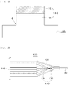
- FIG. 1 is a schematic view showing a conventional electrode tab.
- the conventional electrode tab 10 includes a first tab portion 11 connected to an electrode plate 20 so as to protrude and extend from the electrode plate 20 and a second tab portion 12 extending from the first tab portion 11, the second tab portion being joined to an electrode lead.
- the electrode tab is formed using a method of patterning a connection portion between the electrode tab and the electrode plate so as to have a right angle therebetween by cutting.
- the present invention has been made in view of the above problems, and it is an object of the present invention to provide a battery cell including an electrode tab having a stress relief portion formed at one end thereof in order to reduce stress.
- a battery cell includes an electrode assembly including a plurality of electrode plates and at least one separator interposed between the plurality of electrode plates, a case receiving the electrode assembly therein, electrode tabs protruding and extending from the electrode plates, and an electrode lead joined to the electrode tabs while being electrically connected to the outside, wherein each of the electrode tabs includes a first tab portion connected to a corresponding one of the electrode plates and a second tab portion extending from the first tab portion, the electrode lead being joined to the second tab portion, and the first tab portion has a stress relief portion configured to reduce stress in the electrode tab.
- the stress relief portion may be a corner of a connection portion between the first tab portion and the electrode plate patterned so as to have a predetermined radius of curvature (R).
- the stress relief portion may be a side surface of the first tab portion cut into an arc shape having a predetermined radius of curvature (CR).
- a middle part of the first tab portion between the electrode plate and the second tab portion may have the minimum width.
- the radius of curvature (CR) of the stress relief portion may be less than the length between the electrode plate and the second tab portion.
- the electrode plates may include a positive electrode plate and a negative electrode plate, and each of the positive electrode plate and the negative electrode plate may be provided in the electrode assembly in plural.
- the second tab portions may be formed by stacking the electrode tabs protruding and extending from the plurality of positive electrode plates or the plurality of negative electrode plates.
- the electrode tabs protruding and extending from the positive electrode plates and the electrode tabs protruding and extending from the negative electrode plates may protrude in the same direction.
- the electrode tabs protruding and extending from the positive electrode plates and the electrode tabs protruding and extending from the negative electrode plates may protrude in opposite directions.
- the case may be a pouch-shaped case.
- a battery module according to the present invention includes the battery cell according to the present invention.
- a device according to the present invention includes the battery module according to the present invention.
- a battery cell according to the present invention has an advantage in that an electrode tab is provided with a stress relief portion, whereby stress generated in the electrode tab is reduced when external force is applied to the electrode tab, and therefore it is possible to reduce a danger of the electrode tab being cut.
- FIG. 2 is a sectional view showing a portion of a battery cell according to an embodiment of the present invention.
- the battery cell 100 When describing the battery cell according to the present invention with reference to FIG. 2 , the battery cell 100 according to the present invention includes an electrode assembly 110, a case 120 configured to receive the electrode assembly 110, electrode tabs 130, and an electrode lead 140.
- the electrode assembly 110 is configured to have a structure in which a positive electrode plate, a separator, and a negative electrode plate are alternately stacked. Although a single positive electrode plate and a single negative electrode plate may be provided in the electrode assembly 110, it is preferable for a plurality of positive electrode plates and a plurality of negative electrode plates to be provided in the electrode assembly in consideration of the capacity of the battery cell 100.
- the electrode assembly 110 is classified as a jelly-roll type electrode assembly, which is configured to have a structure in which a long sheet type positive electrode plate having an active material applied thereto and a long sheet type negative electrode plate having an active material applied thereto are wound in the state in which a separator is interposed therebetween, a stacked type electrode assembly, which is configured to have a structure in which a plurality of positive electrode plates having a predetermined size and a plurality of negative electrode plates having a predetermined size are sequentially stacked in the state in which separators are interposed therebetween, or a stacked and folded type electrode assembly, which is configured to have a structure in which stacked type unit cells are wound using a separation film.
- a jelly-roll type electrode assembly which is configured to have a structure in which a long sheet type positive electrode plate having an active material applied thereto and a long sheet type negative electrode plate having an active material applied thereto are wound in the state in which a separator is interposed therebetween
- a stacked type electrode assembly which is configured to
- the case 120 is a sheathing member configured to receive the electrode assembly 110.
- the battery cell may be classified as a cylindrical battery cell having the electrode assembly 110 received in a cylindrical metal can, a prismatic battery cell having the electrode assembly 110 received in a prismatic metal can, or a pouch-shaped battery cell having the electrode assembly 110 received in a pouch-shaped case.
- the pouch-shaped case is generally configured to have a laminate sheet structure including an inner layer, a metal layer, and an outer layer.
- the inner layer is disposed in direct contact with the electrode assembly, and therefore the inner layer must exhibit high insulation properties and high resistance to an electrolytic solution.
- the inner layer must exhibit high sealability in order to hermetically seal the case from the outside, i.e. a thermally-bonded sealed portion between inner layers must exhibit excellent thermal bonding strength.
- the inner layer may be made of a material selected from among a polyolefin-based resin, such as polypropylene, polyethylene, polyethylene acrylate, or polybutylene, a polyurethane resin, and a polyimide resin, which exhibit excellent chemical resistance and high sealability.
- a polyolefin-based resin such as polypropylene, polyethylene, polyethylene acrylate, or polybutylene, a polyurethane resin, and a polyimide resin, which exhibit excellent chemical resistance and high sealability.
- polypropylene which exhibits excellent mechanical-physical properties, such as tensile strength, rigidity, surface hardness, and impact resistance strength, and excellent chemical resistance, is the most preferably used.
- the metal layer which is disposed so as to abut the inner layer, corresponds to a barrier layer configured to prevent moisture or various kinds of gas from permeating into the battery from the outside.
- An aluminum thin film which is light and easily shapeable, may be used as a preferred material for the metal layer.
- the outer layer is provided on the other surface of the metal layer.
- the outer layer may be made of a heat-resistant polymer that exhibits excellent tensile strength, resistance to moisture permeation, and resistance to air permeation such that the outer layer exhibits high heat resistance and chemical resistance while protecting the electrode assembly.
- the outer layer may be made of nylon or polyethylene terephthalate.
- the present invention is not limited thereto.
- FIG. 2 shows that the battery cell 100 is a pouch-shaped battery cell 100 having the electrode assembly received in a pouch-shaped case 120.
- the battery cell 100 according to the present invention is not limited thereto, and any type of battery cell 100 may be used as long as the battery cell 100 is configured such that the electrode tabs 130 protrude from the electrode plates.
- the electrode lead 140 is electrically connected to the outside in a state of being joined to the electrode tabs.
- Various known welding methods such as ultrasonic welding, resistance welding, and laser welding, may be used in order to join the electrode lead and the electrode tabs to each other.
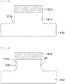
- FIG. 3 is a schematic view showing an electrode tab having a stress relief portion according to an embodiment of the present invention
- FIG. 4 is a schematic view showing an electrode tab having a stress relief portion according to another embodiment of the present invention.
- the electrode tab 130 includes a first tab portion 131a or 131b connected to an electrode plate 150 in a state of protruding and extending therefrom, a second tab portion 132a or 132b extending from the first tab portion 131a or 131b, the electrode lead 140 being joined to the second tab portion 132a or 132b, and a stress relief portion 133a or 133b configured to relieve stress applied to the electrode tab 130.
- the electrode tabs 130 include positive electrode tabs protruding and extending from the positive electrode plates of the electrode assembly 110 and negative electrode tabs protruding and extending from the negative electrode plates of the electrode assembly.
- the positive electrode tabs and the negative electrode tabs are alternately stacked so as to be grouped by polarity.
- the stacked positive electrode tabs may be coupled to each other by ultrasonic welding, resistance welding, and laser welding, and the stacked negative electrode tabs may be coupled to each other by ultrasonic welding, resistance welding, and laser welding.
- the positive electrode tabs and the negative electrode tabs may protrude in the same direction, or may protrude in opposite directions.
- the positive electrode tabs and the negative electrode tabs protrude in the same direction, it is necessary for the positive electrode tabs and the negative electrode tabs to be located so as to avoid interference therebetween.
- the positive electrode tabs are located so as to be biased to one side of the side surface of the electrode assembly from which the electrode tabs 130 protrude, it is preferable for the negative electrode tabs to be located so as to be biased to the other side of the side surface of the electrode assembly opposite the positive electrode tabs.
- the positive electrode tabs and the negative electrode tabs are generally located at the middles of the side surfaces of the electrode assembly from which the positive electrode tabs and the negative electrode tabs protrude, although the location of the positive electrode tabs and the negative electrode tabs is not particularly restricted.
- the electrode tab 130 according to the present invention is provided with a stress relief portion 133 configured to reduce stress generated by internal force/external force applied to the electrode tab 130.
- An example of the stress relief portion 133a is a stress relief portion 133a shown in FIG. 3 .
- the stress relief portion is formed by patterning the corner of a connection portion between the electrode plate 150 and the electrode tab 130, which has low resistance to stress generated in the electrode tab 130, so as not to have a right angle therebetween but to have a predetermined radius of curvature R therebetween.
- the stress relief portion serves to relieve stress concentrated on the corner of the connection portion.
- FIG. 5 is a graph showing the relation between the radius of curvature of the stress relief portion of the electrode tab having the stress relief portion according to the embodiment of the present invention and the maximum value of stress.
- the relation between the radius of curvature of the stress relief portion 133a and the maximum value of stress applied to the electrode tab 130 in the case in which the stress relief portion 133a is provided will be described with reference to FIG. 5 .
- the radius of curvature of the stress relief portion is approximately 4 mm, the maximum value of stress is decreased.
- the radius of curvature of the stress relief portion is 4 mm, the maximum value of stress is the lowest.
- the radius of curvature of the stress relief portion is greater than 4 mm, the maximum value of stress is increased.
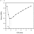
- FIG. 6 is a graph showing the relation between the radius of curvature of the stress relief portion of the electrode tab having the stress relief portion according to the other embodiment of the present invention and the maximum value of stress.
- the stress relief portion 133b is formed by cutting the side surface of the first tab portion 131b of the electrode tab 130 into an arc shape having a predetermined radius of curvature CR.
- the side surface of the first tab portion 131b is cut such that the width of the first tab portion 131b is the minimum at a middle part of the first tab portion.
- the side-cut depth of the side surface of the first tab portion 131b is set such that the radius of curvature CR of the stress relief portion 133b is less than the length between the electrode plate and the second tab portion 132b.
- the maximum value of stress is the minimum when the radius of curvature CR is between 1.5 mm and 2 mm, and the maximum value of stress is increased as the radius of curvature CR is greater than 2 mm.
- the maximum value of stress in the electrode tab 130 having the stress relief portion 133b formed by cutting the side surface of the first tab portion 131b into an arc shape having a predetermined radius of curvature CR is lower than in the other embodiment.
- any one of the two kinds of stress relief portions 133a and 133b may be appropriately selected and applied to the electrode tab 130 in consideration of several conditions of an electrode assembly formation process or conditions necessary for a battery cell 100 to which the stress relief portion is to be applied.
- a battery module so as to include the battery cell 100 having the stress relief portion 133, and the battery module may be used as a power supply source for various devices.
Landscapes
- Chemical & Material Sciences (AREA)
- Chemical Kinetics & Catalysis (AREA)
- Electrochemistry (AREA)
- General Chemical & Material Sciences (AREA)
- Connection Of Batteries Or Terminals (AREA)
- Sealing Battery Cases Or Jackets (AREA)
- Battery Mounting, Suspending (AREA)
Abstract
Description
- This application claims the benefit of priority to
Korean Patent Application No. 2020-0125806 filed on September 28, 2020 - The present invention relates to a battery cell including an electrode tab having a stress relief portion capable of reducing stress generated in an electrode tab, thereby reducing a danger of the electrode tab being cut.
- With technological development of mobile devices, such as smartphones, laptop computers, and digital cameras, and an increase in demand therefor, research on secondary batteries, which are capable of being charged and discharged, has been actively conducted. In addition, secondary batteries, which are energy sources substituting for fossil fuels causing air pollution, have been applied to an electric vehicle (EV), a hybrid electric vehicle (HEV), a plug-in hybrid electric vehicle (P-HEV), and an energy storage system (ESS).
- There are a lithium ion battery, a lithium polymer battery, a nickel-cadmium battery, a nickel-hydride battery, and a nickel-zinc battery as secondary batteries that are widely used at present.
- A secondary battery has an electrode assembly mounted in a battery case, and the electrode assembly is configured to have a structure in which a positive electrode plate, a separator, and a negative electrode plate are stacked and in which an electrode tab protrudes from each of the positive electrode plate and the negative electrode plate.
- In addition, each of the positive electrode plate and the negative electrode plate is formed by applying an active material to a current collector made of metal foil. The electrode tab is formed by cutting the outer portion of the metal foil to which no active material is applied into a predetermined pattern, or may be joined to the metal foil by welding.
- Stress is generated in the electrode tab due to internal force/external force applied to the electrode tab during manufacture or use of the secondary battery.
-
FIG. 1 is a schematic view showing a conventional electrode tab. - As shown in
FIG. 1 , theconventional electrode tab 10 includes afirst tab portion 11 connected to anelectrode plate 20 so as to protrude and extend from theelectrode plate 20 and asecond tab portion 12 extending from thefirst tab portion 11, the second tab portion being joined to an electrode lead. - Conventionally, the electrode tab is formed using a method of patterning a connection portion between the electrode tab and the electrode plate so as to have a right angle therebetween by cutting.
- As a result, stress in the electrode tab is concentrated on the corner C of the connection portion between the
electrode plate 20 and theelectrode tab 10, and therefore a danger of the connection portion on which the stress is concentrated being cut is increased. - The present invention has been made in view of the above problems, and it is an object of the present invention to provide a battery cell including an electrode tab having a stress relief portion formed at one end thereof in order to reduce stress.
- In order to accomplish the above object, a battery cell according to the present invention includes an electrode assembly including a plurality of electrode plates and at least one separator interposed between the plurality of electrode plates, a case receiving the electrode assembly therein, electrode tabs protruding and extending from the electrode plates, and an electrode lead joined to the electrode tabs while being electrically connected to the outside, wherein each of the electrode tabs includes a first tab portion connected to a corresponding one of the electrode plates and a second tab portion extending from the first tab portion, the electrode lead being joined to the second tab portion, and the first tab portion has a stress relief portion configured to reduce stress in the electrode tab.
- Also, in the battery cell according to the present invention, the stress relief portion may be a corner of a connection portion between the first tab portion and the electrode plate patterned so as to have a predetermined radius of curvature (R).
- Also, in the battery cell according to the present invention, the stress relief portion may be a side surface of the first tab portion cut into an arc shape having a predetermined radius of curvature (CR).
- Also, in the battery cell according to the present invention, a middle part of the first tab portion between the electrode plate and the second tab portion may have the minimum width.
- Also, in the battery cell according to the present invention, the radius of curvature (CR) of the stress relief portion may be less than the length between the electrode plate and the second tab portion.
- Also, in the battery cell according to the present invention, the electrode plates may include a positive electrode plate and a negative electrode plate, and each of the positive electrode plate and the negative electrode plate may be provided in the electrode assembly in plural.
- Also, in the battery cell according to the present invention, the second tab portions may be formed by stacking the electrode tabs protruding and extending from the plurality of positive electrode plates or the plurality of negative electrode plates.
- Also, in the battery cell according to the present invention, the electrode tabs protruding and extending from the positive electrode plates and the electrode tabs protruding and extending from the negative electrode plates may protrude in the same direction.
- Also, in the battery cell according to the present invention, the electrode tabs protruding and extending from the positive electrode plates and the electrode tabs protruding and extending from the negative electrode plates may protrude in opposite directions.
- Also, in the battery cell according to the present invention, the case may be a pouch-shaped case.
- In addition, a battery module according to the present invention includes the battery cell according to the present invention.
- In addition, a device according to the present invention includes the battery module according to the present invention.
- A battery cell according to the present invention has an advantage in that an electrode tab is provided with a stress relief portion, whereby stress generated in the electrode tab is reduced when external force is applied to the electrode tab, and therefore it is possible to reduce a danger of the electrode tab being cut.
-
-
FIG. 1 is a schematic view showing a conventional electrode tab. -
FIG. 2 is a sectional view showing a portion of a battery cell according to an embodiment of the present invention. -
FIG. 3 is a schematic view showing an electrode tab having a stress relief portion according to an embodiment of the present invention. -
FIG. 4 is a schematic view showing an electrode tab having a stress relief portion according to another embodiment of the present invention. -
FIG. 5 is a graph showing the relation between the radius of curvature of the stress relief portion of the electrode tab having the stress relief portion according to the embodiment of the present invention and the maximum value of stress. -
FIG. 6 is a graph showing the relation between the radius of curvature of the stress relief portion of the electrode tab having the stress relief portion according to the other embodiment of the present invention and the maximum value of stress. - In the present application, it should be understood that the terms "comprises," "has," "includes," etc. specify the presence of stated features, numbers, steps, operations, elements, components, or combinations thereof, but do not preclude the presence or addition of one or more other features, numbers, steps, operations, elements, components, or combinations thereof.
- In addition, the same reference numbers will be used throughout the drawings to refer to parts that perform similar functions or operations. In the case in which one part is said to be connected to another part in the specification, not only may the one part be directly connected to the other part, but also, the one part may be indirectly connected to the other part via a further part. In addition, that a certain element is included does not mean that other elements are excluded, but means that such elements may be further included unless mentioned otherwise.
- Hereinafter, a battery cell according to the present invention will be described with reference to the accompanying drawings.
-
FIG. 2 is a sectional view showing a portion of a battery cell according to an embodiment of the present invention. - When describing the battery cell according to the present invention with reference to
FIG. 2 , thebattery cell 100 according to the present invention includes anelectrode assembly 110, acase 120 configured to receive theelectrode assembly 110,electrode tabs 130, and anelectrode lead 140. - First, the
electrode assembly 110 is configured to have a structure in which a positive electrode plate, a separator, and a negative electrode plate are alternately stacked. Although a single positive electrode plate and a single negative electrode plate may be provided in theelectrode assembly 110, it is preferable for a plurality of positive electrode plates and a plurality of negative electrode plates to be provided in the electrode assembly in consideration of the capacity of thebattery cell 100. - Meanwhile, the
electrode assembly 110 is classified as a jelly-roll type electrode assembly, which is configured to have a structure in which a long sheet type positive electrode plate having an active material applied thereto and a long sheet type negative electrode plate having an active material applied thereto are wound in the state in which a separator is interposed therebetween, a stacked type electrode assembly, which is configured to have a structure in which a plurality of positive electrode plates having a predetermined size and a plurality of negative electrode plates having a predetermined size are sequentially stacked in the state in which separators are interposed therebetween, or a stacked and folded type electrode assembly, which is configured to have a structure in which stacked type unit cells are wound using a separation film. - The
case 120 is a sheathing member configured to receive theelectrode assembly 110. Based on the shape of thecase 120, the battery cell may be classified as a cylindrical battery cell having theelectrode assembly 110 received in a cylindrical metal can, a prismatic battery cell having theelectrode assembly 110 received in a prismatic metal can, or a pouch-shaped battery cell having theelectrode assembly 110 received in a pouch-shaped case. - The pouch-shaped case is generally configured to have a laminate sheet structure including an inner layer, a metal layer, and an outer layer. The inner layer is disposed in direct contact with the electrode assembly, and therefore the inner layer must exhibit high insulation properties and high resistance to an electrolytic solution. In addition, the inner layer must exhibit high sealability in order to hermetically seal the case from the outside, i.e. a thermally-bonded sealed portion between inner layers must exhibit excellent thermal bonding strength.
- The inner layer may be made of a material selected from among a polyolefin-based resin, such as polypropylene, polyethylene, polyethylene acrylate, or polybutylene, a polyurethane resin, and a polyimide resin, which exhibit excellent chemical resistance and high sealability. However, the present invention is not limited thereto, and polypropylene, which exhibits excellent mechanical-physical properties, such as tensile strength, rigidity, surface hardness, and impact resistance strength, and excellent chemical resistance, is the most preferably used.
- The metal layer, which is disposed so as to abut the inner layer, corresponds to a barrier layer configured to prevent moisture or various kinds of gas from permeating into the battery from the outside. An aluminum thin film, which is light and easily shapeable, may be used as a preferred material for the metal layer.
- The outer layer is provided on the other surface of the metal layer. The outer layer may be made of a heat-resistant polymer that exhibits excellent tensile strength, resistance to moisture permeation, and resistance to air permeation such that the outer layer exhibits high heat resistance and chemical resistance while protecting the electrode assembly. As an example, the outer layer may be made of nylon or polyethylene terephthalate. However, the present invention is not limited thereto.
-
FIG. 2 shows that thebattery cell 100 is a pouch-shaped battery cell 100 having the electrode assembly received in a pouch-shaped case 120. However, thebattery cell 100 according to the present invention is not limited thereto, and any type ofbattery cell 100 may be used as long as thebattery cell 100 is configured such that theelectrode tabs 130 protrude from the electrode plates. - In addition, the
electrode lead 140 is electrically connected to the outside in a state of being joined to the electrode tabs. Various known welding methods, such as ultrasonic welding, resistance welding, and laser welding, may be used in order to join the electrode lead and the electrode tabs to each other. -
FIG. 3 is a schematic view showing an electrode tab having a stress relief portion according to an embodiment of the present invention, andFIG. 4 is a schematic view showing an electrode tab having a stress relief portion according to another embodiment of the present invention. - When describing the
electrode tab 130 according to the present invention in detail with reference toFIGS. 3 and 4 , theelectrode tab 130 includes afirst tab portion electrode plate 150 in a state of protruding and extending therefrom, asecond tab portion first tab portion electrode lead 140 being joined to thesecond tab portion stress relief portion electrode tab 130. - The
electrode tabs 130 include positive electrode tabs protruding and extending from the positive electrode plates of theelectrode assembly 110 and negative electrode tabs protruding and extending from the negative electrode plates of the electrode assembly. The positive electrode tabs and the negative electrode tabs are alternately stacked so as to be grouped by polarity. The stacked positive electrode tabs may be coupled to each other by ultrasonic welding, resistance welding, and laser welding, and the stacked negative electrode tabs may be coupled to each other by ultrasonic welding, resistance welding, and laser welding. - Here, the positive electrode tabs and the negative electrode tabs may protrude in the same direction, or may protrude in opposite directions.
- In the case in which the positive electrode tabs and the negative electrode tabs protrude in the same direction, it is necessary for the positive electrode tabs and the negative electrode tabs to be located so as to avoid interference therebetween.
- For example, in the case in which the positive electrode tabs are located so as to be biased to one side of the side surface of the electrode assembly from which the
electrode tabs 130 protrude, it is preferable for the negative electrode tabs to be located so as to be biased to the other side of the side surface of the electrode assembly opposite the positive electrode tabs. - Meanwhile, in the case in which the positive electrode tabs and the negative electrode tabs protrude in opposite directions, the positive electrode tabs and the negative electrode tabs are generally located at the middles of the side surfaces of the electrode assembly from which the positive electrode tabs and the negative electrode tabs protrude, although the location of the positive electrode tabs and the negative electrode tabs is not particularly restricted.
- In addition, the
electrode tab 130 according to the present invention is provided with a stress relief portion 133 configured to reduce stress generated by internal force/external force applied to theelectrode tab 130. - An example of the
stress relief portion 133a is astress relief portion 133a shown inFIG. 3 . - The stress relief portion is formed by patterning the corner of a connection portion between the
electrode plate 150 and theelectrode tab 130, which has low resistance to stress generated in theelectrode tab 130, so as not to have a right angle therebetween but to have a predetermined radius of curvature R therebetween. The stress relief portion serves to relieve stress concentrated on the corner of the connection portion. -
FIG. 5 is a graph showing the relation between the radius of curvature of the stress relief portion of the electrode tab having the stress relief portion according to the embodiment of the present invention and the maximum value of stress. - The relation between the radius of curvature of the
stress relief portion 133a and the maximum value of stress applied to theelectrode tab 130 in the case in which thestress relief portion 133a is provided will be described with reference toFIG. 5 . As the radius of curvature of the stress relief portion is approximately 4 mm, the maximum value of stress is decreased. When the radius of curvature of the stress relief portion is 4 mm, the maximum value of stress is the lowest. As the radius of curvature of the stress relief portion is greater than 4 mm, the maximum value of stress is increased. - That is, it can be seen that, when the radius of curvature R of the
stress relief portion 133a is 4 mm, stress is the minimum. -
FIG. 6 is a graph showing the relation between the radius of curvature of the stress relief portion of the electrode tab having the stress relief portion according to the other embodiment of the present invention and the maximum value of stress. - When describing the
stress relief portion 133b with reference toFIGS. 4 and6 , thestress relief portion 133b is formed by cutting the side surface of thefirst tab portion 131b of theelectrode tab 130 into an arc shape having a predetermined radius of curvature CR. - That is, the side surface of the
first tab portion 131b is cut such that the width of thefirst tab portion 131b is the minimum at a middle part of the first tab portion. - In the case in which the side surface of the
first tab portion 131b is cut (side-cut), as described above, it is possible to disperse stress concentrated on the corner of the connection portion between theelectrode plate 150 and theelectrode tab 130. - In consideration of the fact that mechanical strength of the
first tab portion 131b and the amount of current that flows in the first tab portion are proportional to the area of a conductor, however, it is preferable for the side-cut depth of the side surface of thefirst tab portion 131b to be set such that the radius of curvature CR of thestress relief portion 133b is less than the length between the electrode plate and thesecond tab portion 132b. - In the relation between the radius of curvature CR of the
stress relief portion 133b and the maximum value of stress, the maximum value of stress is the minimum when the radius of curvature CR is between 1.5 mm and 2 mm, and the maximum value of stress is increased as the radius of curvature CR is greater than 2 mm. - Meanwhile, when comparing the above two embodiments with each other, it can be seen that the maximum value of stress in the
electrode tab 130 having thestress relief portion 133b formed by cutting the side surface of thefirst tab portion 131b into an arc shape having a predetermined radius of curvature CR is lower than in the other embodiment. - However, any one of the two kinds of
stress relief portions electrode tab 130 in consideration of several conditions of an electrode assembly formation process or conditions necessary for abattery cell 100 to which the stress relief portion is to be applied. - As described above, it is possible to reduce stress generated in the
electrode tab 130 by forming the stress relief portion 133, whereby it is possible to reduce a danger of theelectrode tab 130 being cut. - In addition, it is possible to manufacture a battery module so as to include the
battery cell 100 having the stress relief portion 133, and the battery module may be used as a power supply source for various devices. - Although the specific details of the present invention have been described in detail, those skilled in the art will appreciate that the detailed description thereof discloses only preferred embodiments of the present invention and thus does not limit the scope of the present invention. Accordingly, those skilled in the art will appreciate that various changes and modifications are possible, without departing from the category and technical idea of the present invention, and it will be obvious that such changes and modifications fall within the scope of the appended claims.
-
- 100: Battery cell
- 110: Electrode assembly
- 120: Case
- 130: Electrode tab
- 131, 131a, 131b: First tab portions
- 132, 132a, 132b: Second tab portions
- 133, 133a, 133b: Stress relief portions
- 140: Electrode lead
- 150: Electrode plate
Claims (12)
- A battery cell (100) comprising:an electrode assembly (110) comprising a plurality of electrode plates (150) and at least one separator interposed between the plurality of electrode plates (150);a case (120) receiving the electrode assembly (110) therein;electrode tabs (130) protruding and extending from the electrode plates (150); andan electrode lead (140) joined to the electrode tabs (130) while being electrically connected to an outside, wherein each of the electrode tabs (130) comprises:a first tab portion (131) connected to a corresponding one of the electrode plates (150); anda second tab portion (132) extending from the first tab portion (131), the electrode lead (140) being joined to the second tab portion, andwherein the first tab portion (131) has a stress relief portion (133) configured to reduce stress in the electrode tab (130).
- The battery cell (100) according to claim 1, wherein the stress relief portion (133a) is a corner of a connection portion between the first tab portion (131a) and the electrode plate (150) patterned so as to have a predetermined radius of curvature (R).
- The battery cell (100) according to claim 1, wherein the stress relief portion (133b) is a side surface of the first tab portion (131b) cut into an arc shape having a predetermined radius of curvature (CR).
- The battery cell (100) according to claim 3, wherein a middle part of the first tab portion (131b) between the electrode plate (150) and the second tab portion (132b) has a minimum width.
- The battery cell (100) according to claim 3, wherein the radius of curvature (CR) of the stress relief portion (133b) is less than a length between the electrode plate (150) and the second tab portion (132b).
- The battery cell (100) according to claim 1, wherein the electrode plates (150) comprise a positive electrode plate and a negative electrode plate, and
wherein each of the positive electrode plate and the negative electrode plate is provided in the electrode assembly in plural. - The battery cell (100) according to claim 6, wherein the second tab portions (132) are formed by stacking the electrode tabs (130) protruding and extending from the plurality of positive electrode plates or the plurality of negative electrode plates.
- The battery cell (100) according to claim 7, wherein the electrode tabs (130) protruding and extending from the positive electrode plates and the electrode tabs (130) protruding and extending from the negative electrode plates protrude in an identical direction.
- The battery cell (100) according to claim 7, wherein the electrode tabs (130) protruding and extending from the positive electrode plates and the electrode tabs (130) protruding and extending from the negative electrode plates protrude in opposite directions.
- The battery cell (100) according to claim 1, wherein the case (120) is a pouch-shaped case.
- A battery module comprising the battery cell (100) according to any one of claims 1 to 10.
- A device comprising the battery module according to claim 11.
Applications Claiming Priority (2)
| Application Number | Priority Date | Filing Date | Title |
|---|---|---|---|
| KR1020200125806A KR102956955B1 (en) | 2020-09-28 | Battery cell including electrode tabs on which stress relief portions are formed | |
| PCT/KR2021/011360 WO2022065708A1 (en) | 2020-09-28 | 2021-08-25 | Battery cell comprising electrode tab having stress-relieving portion formed thereon |
Publications (3)
| Publication Number | Publication Date |
|---|---|
| EP4113733A1 true EP4113733A1 (en) | 2023-01-04 |
| EP4113733A4 EP4113733A4 (en) | 2024-09-18 |
| EP4113733B1 EP4113733B1 (en) | 2025-11-19 |
Family
ID=80846771
Family Applications (1)
| Application Number | Title | Priority Date | Filing Date |
|---|---|---|---|
| EP21872738.6A Active EP4113733B1 (en) | 2020-09-28 | 2021-08-25 | Battery cell including electrode tab having stress relief portion |
Country Status (6)
| Country | Link |
|---|---|
| US (1) | US20230198106A1 (en) |
| EP (1) | EP4113733B1 (en) |
| JP (1) | JP7570755B2 (en) |
| CN (1) | CN115699443A (en) |
| ES (1) | ES3055530T3 (en) |
| WO (1) | WO2022065708A1 (en) |
Families Citing this family (2)
| Publication number | Priority date | Publication date | Assignee | Title |
|---|---|---|---|---|
| US20240136670A1 (en) * | 2021-11-18 | 2024-04-25 | Zhuhai Cosmx Battery Co., Ltd. | Electrode assembly and battery |
| KR20240038454A (en) * | 2022-09-16 | 2024-03-25 | 주식회사 엘지에너지솔루션 | Electrode assembly having an electrode tab junction structure and secondary battery comprising the same |
Family Cites Families (16)
| Publication number | Priority date | Publication date | Assignee | Title |
|---|---|---|---|---|
| JPH1116577A (en) * | 1997-06-26 | 1999-01-22 | Shin Kobe Electric Mach Co Ltd | Non-aqueous electrolyte battery |
| JP2012519366A (en) * | 2009-03-02 | 2012-08-23 | エルジー ケム. エルティーディ. | Pouch and secondary battery including the same |
| CN201562709U (en) * | 2009-07-15 | 2010-08-25 | 深圳邦凯新能源股份有限公司 | Lithium battery pole piece |
| US20110206976A1 (en) * | 2010-02-19 | 2011-08-25 | Kyung-Mo Yoo | Electrode assembly and secondary battery using the same |
| JP5618706B2 (en) * | 2010-08-26 | 2014-11-05 | 日立マクセル株式会社 | Stacked battery |
| US8968907B2 (en) * | 2010-08-30 | 2015-03-03 | Samsung Sdi Co., Ltd. | Battery pack |
| EP2500972B1 (en) * | 2010-12-20 | 2017-07-26 | LG Chem, Ltd. | Lithium secondary battery having multi-directional lead-tab structure |
| JP2013073757A (en) * | 2011-09-27 | 2013-04-22 | Panasonic Corp | Electrode plate and wound type electrode battery |
| KR101447064B1 (en) * | 2012-03-26 | 2014-10-07 | 주식회사 엘지화학 | Battery Cell of Improved Connection Reliability and Battery Pack Comprising the Same |
| JP2013214464A (en) * | 2012-04-04 | 2013-10-17 | Mitsubishi Heavy Ind Ltd | Battery |
| JP2014022116A (en) * | 2012-07-13 | 2014-02-03 | Shin Kobe Electric Mach Co Ltd | Electrode plate for secondary battery, and method for manufacturing electrode plate for secondary battery |
| KR102107000B1 (en) * | 2015-12-14 | 2020-05-06 | 주식회사 엘지화학 | Electrode Assembly Employed with Recess Portion on Electrode Plate and Secondary Battery Comprising the Same |
| KR101783703B1 (en) * | 2017-03-17 | 2017-10-11 | 주식회사 리베스트 | Flexible battery having joint structure metal strengthening tab and bending joint structure |
| JP2019061878A (en) * | 2017-09-27 | 2019-04-18 | Tdk株式会社 | Electrochemical device |
| KR102295756B1 (en) * | 2018-06-19 | 2021-09-01 | 에스케이이노베이션 주식회사 | Battery having multi electrode-lead and The battery module |
| KR102214591B1 (en) | 2019-04-25 | 2021-02-15 | 링크플로우 주식회사 | Hook joining device and electronic device having the same |
-
2021
- 2021-08-25 JP JP2022565684A patent/JP7570755B2/en active Active
- 2021-08-25 US US17/914,978 patent/US20230198106A1/en active Pending
- 2021-08-25 CN CN202180025454.2A patent/CN115699443A/en active Pending
- 2021-08-25 ES ES21872738T patent/ES3055530T3/en active Active
- 2021-08-25 WO PCT/KR2021/011360 patent/WO2022065708A1/en not_active Ceased
- 2021-08-25 EP EP21872738.6A patent/EP4113733B1/en active Active
Also Published As
| Publication number | Publication date |
|---|---|
| US20230198106A1 (en) | 2023-06-22 |
| ES3055530T3 (en) | 2026-02-12 |
| JP7570755B2 (en) | 2024-10-22 |
| WO2022065708A1 (en) | 2022-03-31 |
| CN115699443A (en) | 2023-02-03 |
| EP4113733A4 (en) | 2024-09-18 |
| EP4113733B1 (en) | 2025-11-19 |
| KR20220042683A (en) | 2022-04-05 |
| JP2023523618A (en) | 2023-06-06 |
Similar Documents
| Publication | Publication Date | Title |
|---|---|---|
| US11437683B2 (en) | Battery cell of venting structure using taping | |
| EP3907818B1 (en) | Battery pack having movable busbar assembly and secondary battery including the same | |
| CN114976405B (en) | Riveting structure for electrode terminals and secondary batteries, battery packs and automobiles including them. | |
| EP4131584B1 (en) | Battery module including thermal insulation member | |
| EP2602840A2 (en) | Secondary battery pouch having improved stability, pouch-type secondary battery using same, and medium- or large-sized battery pack | |
| EP4243163A1 (en) | Secondary battery | |
| EP4080644B1 (en) | Electrode assembly including disconnection preventing layer and method for manufacturing the same | |
| EP4191761B1 (en) | Battery cell and battery cell manufacturing apparatus | |
| EP4075562B1 (en) | Battery cell with improved safety and method of manufacturing the same | |
| EP4113733B1 (en) | Battery cell including electrode tab having stress relief portion | |
| EP4195377A1 (en) | Battery cell and battery module comprising same | |
| KR102711924B1 (en) | Battery module having structure for preventing degradation and Battery pack having the same | |
| US20240106064A1 (en) | Secondary Battery, Battery Pack and Device Including the Same | |
| US20240097177A1 (en) | Electrode Assembly and Battery Cell Including the Same | |
| KR102956955B1 (en) | Battery cell including electrode tabs on which stress relief portions are formed | |
| EP4564547A1 (en) | Battery cell and battery module including the same | |
| EP4243194A1 (en) | Pouch-type battery cell with improved thermal stability | |
| US20250087834A1 (en) | Electrode assembly and rechargeable battery including the same | |
| US20250149724A1 (en) | Rechargeable battery | |
| KR20260031422A (en) | Battery cell and battery pack and vehicle including the same | |
| KR20260058694A (en) | Battery cell and, battery pack and vehicle including the same and, current collector plate | |
| JP2024538841A (en) | Electrode assembly and manufacturing method thereof | |
| KR20260005050A (en) | Battery cell and battery pack and vehicle including the same | |
| CN117795716A (en) | Electrode assemblies, batteries, and battery packs and vehicles including battery packs | |
| KR20210109824A (en) | Battery module with busbar frame for preventing spring back of cell lead and battery pack including the same |
Legal Events
| Date | Code | Title | Description |
|---|---|---|---|
| STAA | Information on the status of an ep patent application or granted ep patent |
Free format text: STATUS: THE INTERNATIONAL PUBLICATION HAS BEEN MADE |
|
| PUAI | Public reference made under article 153(3) epc to a published international application that has entered the european phase |
Free format text: ORIGINAL CODE: 0009012 |
|
| STAA | Information on the status of an ep patent application or granted ep patent |
Free format text: STATUS: REQUEST FOR EXAMINATION WAS MADE |
|
| 17P | Request for examination filed |
Effective date: 20220928 |
|
| AK | Designated contracting states |
Kind code of ref document: A1 Designated state(s): AL AT BE BG CH CY CZ DE DK EE ES FI FR GB GR HR HU IE IS IT LI LT LU LV MC MK MT NL NO PL PT RO RS SE SI SK SM TR |
|
| DAV | Request for validation of the european patent (deleted) | ||
| DAX | Request for extension of the european patent (deleted) | ||
| A4 | Supplementary search report drawn up and despatched |
Effective date: 20240821 |
|
| RIC1 | Information provided on ipc code assigned before grant |
Ipc: H01M 50/54 20210101ALI20240814BHEP Ipc: H01M 50/533 20210101ALI20240814BHEP Ipc: H01M 50/543 20210101ALI20240814BHEP Ipc: H01M 50/116 20210101ALI20240814BHEP Ipc: H01M 50/531 20210101ALI20240814BHEP Ipc: H01M 50/572 20210101AFI20240814BHEP |
|
| STAA | Information on the status of an ep patent application or granted ep patent |
Free format text: STATUS: EXAMINATION IS IN PROGRESS |
|
| 17Q | First examination report despatched |
Effective date: 20250312 |
|
| GRAP | Despatch of communication of intention to grant a patent |
Free format text: ORIGINAL CODE: EPIDOSNIGR1 |
|
| STAA | Information on the status of an ep patent application or granted ep patent |
Free format text: STATUS: GRANT OF PATENT IS INTENDED |
|
| INTG | Intention to grant announced |
Effective date: 20250728 |
|
| GRAS | Grant fee paid |
Free format text: ORIGINAL CODE: EPIDOSNIGR3 |
|
| P01 | Opt-out of the competence of the unified patent court (upc) registered |
Free format text: CASE NUMBER: UPC_APP_4885_4113733/2025 Effective date: 20250827 |
|
| GRAA | (expected) grant |
Free format text: ORIGINAL CODE: 0009210 |
|
| STAA | Information on the status of an ep patent application or granted ep patent |
Free format text: STATUS: THE PATENT HAS BEEN GRANTED |
|
| AK | Designated contracting states |
Kind code of ref document: B1 Designated state(s): AL AT BE BG CH CY CZ DE DK EE ES FI FR GB GR HR HU IE IS IT LI LT LU LV MC MK MT NL NO PL PT RO RS SE SI SK SM TR |
|
| REG | Reference to a national code |
Ref country code: CH Ref legal event code: F10 Free format text: ST27 STATUS EVENT CODE: U-0-0-F10-F00 (AS PROVIDED BY THE NATIONAL OFFICE) Effective date: 20251119 Ref country code: GB Ref legal event code: FG4D |
|
| REG | Reference to a national code |
Ref country code: DE Ref legal event code: R096 Ref document number: 602021042814 Country of ref document: DE |
|
| REG | Reference to a national code |
Ref country code: IE Ref legal event code: FG4D |
|
| REG | Reference to a national code |
Ref country code: ES Ref legal event code: FG2A Ref document number: 3055530 Country of ref document: ES Kind code of ref document: T3 Effective date: 20260212 |
|
| REG | Reference to a national code |
Ref country code: NL Ref legal event code: MP Effective date: 20251119 |
|
| REG | Reference to a national code |
Ref country code: LT Ref legal event code: MG9D |
|
| PG25 | Lapsed in a contracting state [announced via postgrant information from national office to epo] |
Ref country code: NO Free format text: LAPSE BECAUSE OF FAILURE TO SUBMIT A TRANSLATION OF THE DESCRIPTION OR TO PAY THE FEE WITHIN THE PRESCRIBED TIME-LIMIT Effective date: 20260219 |
|
| PG25 | Lapsed in a contracting state [announced via postgrant information from national office to epo] |
Ref country code: FI Free format text: LAPSE BECAUSE OF FAILURE TO SUBMIT A TRANSLATION OF THE DESCRIPTION OR TO PAY THE FEE WITHIN THE PRESCRIBED TIME-LIMIT Effective date: 20251119 Ref country code: HR Free format text: LAPSE BECAUSE OF FAILURE TO SUBMIT A TRANSLATION OF THE DESCRIPTION OR TO PAY THE FEE WITHIN THE PRESCRIBED TIME-LIMIT Effective date: 20251119 Ref country code: AT Free format text: LAPSE BECAUSE OF FAILURE TO SUBMIT A TRANSLATION OF THE DESCRIPTION OR TO PAY THE FEE WITHIN THE PRESCRIBED TIME-LIMIT Effective date: 20251119 |
|
| REG | Reference to a national code |
Ref country code: AT Ref legal event code: MK05 Ref document number: 1859687 Country of ref document: AT Kind code of ref document: T Effective date: 20251119 |
|
| PG25 | Lapsed in a contracting state [announced via postgrant information from national office to epo] |
Ref country code: NL Free format text: LAPSE BECAUSE OF FAILURE TO SUBMIT A TRANSLATION OF THE DESCRIPTION OR TO PAY THE FEE WITHIN THE PRESCRIBED TIME-LIMIT Effective date: 20251119 |
|
| PG25 | Lapsed in a contracting state [announced via postgrant information from national office to epo] |
Ref country code: RS Free format text: LAPSE BECAUSE OF FAILURE TO SUBMIT A TRANSLATION OF THE DESCRIPTION OR TO PAY THE FEE WITHIN THE PRESCRIBED TIME-LIMIT Effective date: 20260219 |
|
| PG25 | Lapsed in a contracting state [announced via postgrant information from national office to epo] |
Ref country code: IS Free format text: LAPSE BECAUSE OF FAILURE TO SUBMIT A TRANSLATION OF THE DESCRIPTION OR TO PAY THE FEE WITHIN THE PRESCRIBED TIME-LIMIT Effective date: 20260319 |
|
| PG25 | Lapsed in a contracting state [announced via postgrant information from national office to epo] |
Ref country code: PT Free format text: LAPSE BECAUSE OF FAILURE TO SUBMIT A TRANSLATION OF THE DESCRIPTION OR TO PAY THE FEE WITHIN THE PRESCRIBED TIME-LIMIT Effective date: 20260319 |
|
| PG25 | Lapsed in a contracting state [announced via postgrant information from national office to epo] |
Ref country code: PL Free format text: LAPSE BECAUSE OF FAILURE TO SUBMIT A TRANSLATION OF THE DESCRIPTION OR TO PAY THE FEE WITHIN THE PRESCRIBED TIME-LIMIT Effective date: 20251119 |
|
| PG25 | Lapsed in a contracting state [announced via postgrant information from national office to epo] |
Ref country code: LV Free format text: LAPSE BECAUSE OF FAILURE TO SUBMIT A TRANSLATION OF THE DESCRIPTION OR TO PAY THE FEE WITHIN THE PRESCRIBED TIME-LIMIT Effective date: 20251119 |