EP4113717A1 - Battery pack case comprising over-fusion prevention structure - Google Patents
Battery pack case comprising over-fusion prevention structure Download PDFInfo
- Publication number
- EP4113717A1 EP4113717A1 EP21895165.5A EP21895165A EP4113717A1 EP 4113717 A1 EP4113717 A1 EP 4113717A1 EP 21895165 A EP21895165 A EP 21895165A EP 4113717 A1 EP4113717 A1 EP 4113717A1
- Authority
- EP
- European Patent Office
- Prior art keywords
- case
- battery pack
- projecting portion
- grooved
- coupled
- Prior art date
- Legal status (The legal status is an assumption and is not a legal conclusion. Google has not performed a legal analysis and makes no representation as to the accuracy of the status listed.)
- Granted
Links
Images


Classifications
-
- H—ELECTRICITY
- H01—ELECTRIC ELEMENTS
- H01M—PROCESSES OR MEANS, e.g. BATTERIES, FOR THE DIRECT CONVERSION OF CHEMICAL ENERGY INTO ELECTRICAL ENERGY
- H01M50/00—Constructional details or processes of manufacture of the non-active parts of electrochemical cells other than fuel cells, e.g. hybrid cells
- H01M50/20—Mountings; Secondary casings or frames; Racks, modules or packs; Suspension devices; Shock absorbers; Transport or carrying devices; Holders
- H01M50/204—Racks, modules or packs for multiple batteries or multiple cells
- H01M50/207—Racks, modules or packs for multiple batteries or multiple cells characterised by their shape
-
- H—ELECTRICITY
- H01—ELECTRIC ELEMENTS
- H01M—PROCESSES OR MEANS, e.g. BATTERIES, FOR THE DIRECT CONVERSION OF CHEMICAL ENERGY INTO ELECTRICAL ENERGY
- H01M50/00—Constructional details or processes of manufacture of the non-active parts of electrochemical cells other than fuel cells, e.g. hybrid cells
- H01M50/20—Mountings; Secondary casings or frames; Racks, modules or packs; Suspension devices; Shock absorbers; Transport or carrying devices; Holders
- H01M50/204—Racks, modules or packs for multiple batteries or multiple cells
-
- H—ELECTRICITY
- H01—ELECTRIC ELEMENTS
- H01M—PROCESSES OR MEANS, e.g. BATTERIES, FOR THE DIRECT CONVERSION OF CHEMICAL ENERGY INTO ELECTRICAL ENERGY
- H01M50/00—Constructional details or processes of manufacture of the non-active parts of electrochemical cells other than fuel cells, e.g. hybrid cells
- H01M50/20—Mountings; Secondary casings or frames; Racks, modules or packs; Suspension devices; Shock absorbers; Transport or carrying devices; Holders
-
- B—PERFORMING OPERATIONS; TRANSPORTING
- B29—WORKING OF PLASTICS; WORKING OF SUBSTANCES IN A PLASTIC STATE IN GENERAL
- B29C—SHAPING OR JOINING OF PLASTICS; SHAPING OF MATERIAL IN A PLASTIC STATE, NOT OTHERWISE PROVIDED FOR; AFTER-TREATMENT OF THE SHAPED PRODUCTS, e.g. REPAIRING
- B29C65/00—Joining or sealing of preformed parts, e.g. welding of plastics materials; Apparatus therefor
- B29C65/02—Joining or sealing of preformed parts, e.g. welding of plastics materials; Apparatus therefor by heating, with or without pressure
- B29C65/08—Joining or sealing of preformed parts, e.g. welding of plastics materials; Apparatus therefor by heating, with or without pressure using ultrasonic vibrations
-
- B—PERFORMING OPERATIONS; TRANSPORTING
- B29—WORKING OF PLASTICS; WORKING OF SUBSTANCES IN A PLASTIC STATE IN GENERAL
- B29C—SHAPING OR JOINING OF PLASTICS; SHAPING OF MATERIAL IN A PLASTIC STATE, NOT OTHERWISE PROVIDED FOR; AFTER-TREATMENT OF THE SHAPED PRODUCTS, e.g. REPAIRING
- B29C65/00—Joining or sealing of preformed parts, e.g. welding of plastics materials; Apparatus therefor
- B29C65/56—Joining or sealing of preformed parts, e.g. welding of plastics materials; Apparatus therefor using mechanical means or mechanical connections, e.g. form-fits
-
- B—PERFORMING OPERATIONS; TRANSPORTING
- B29—WORKING OF PLASTICS; WORKING OF SUBSTANCES IN A PLASTIC STATE IN GENERAL
- B29L—INDEXING SCHEME ASSOCIATED WITH SUBCLASS B29C, RELATING TO PARTICULAR ARTICLES
- B29L2031/00—Other particular articles
- B29L2031/712—Containers; Packaging elements or accessories, Packages
- B29L2031/7146—Battery-cases
-
- Y—GENERAL TAGGING OF NEW TECHNOLOGICAL DEVELOPMENTS; GENERAL TAGGING OF CROSS-SECTIONAL TECHNOLOGIES SPANNING OVER SEVERAL SECTIONS OF THE IPC; TECHNICAL SUBJECTS COVERED BY FORMER USPC CROSS-REFERENCE ART COLLECTIONS [XRACs] AND DIGESTS
- Y02—TECHNOLOGIES OR APPLICATIONS FOR MITIGATION OR ADAPTATION AGAINST CLIMATE CHANGE
- Y02E—REDUCTION OF GREENHOUSE GAS [GHG] EMISSIONS, RELATED TO ENERGY GENERATION, TRANSMISSION OR DISTRIBUTION
- Y02E60/00—Enabling technologies; Technologies with a potential or indirect contribution to GHG emissions mitigation
- Y02E60/10—Energy storage using batteries
Definitions
- the present invention relates to a battery pack case including an over-fusion prevention structure. More particularly, the present invention relates to a battery pack case including an over-fusion prevention structure capable of preventing external defects from occurring on a coupling portion of the battery pack case due to over-fusion when ultrasonic welding is performed for coupling of the battery pack case.
- a battery pack constituted by secondary batteries connected to each other in series or in parallel is used as an energy source for medium- or large-sized devices, which require high output and high capacity.
- the battery pack may include a plurality of battery cells, a structure configured to perform electrical connection between the battery cells, a structure configured to control the operation of the battery cells, and a structure configured to adjusting heat generation/heat dissipation of the battery cells in a battery pack case, and coupling of the battery pack case is performed in the state in which the structures are received therein to manufacture the battery pack.
- a coupling method of a battery pack case manufactured using a polymer resin there is used a method of pressurizing the polymer resin in a molten state using frictional heat by ultrasonic vibration in order to achieve fusion. If a joint of the battery pack case is over-fused or pressing force is inaccurately controlled, the molten resin flows outwards, whereby burrs are generated.
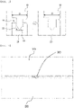
- FIG. 1 is a vertical sectional view of a coupling portion of a conventional battery pack case
- FIG. 2 is a front view of the coupling portion of the battery pack case of FIG. 1 .
- the battery pack case is constituted by a first case 10 located above and a second case 20 located below.
- a projecting portion 11 is formed on a coupling portion of the first case 10 at a middle part of the first case in a thickness direction D thereof so as to project downwards therefrom, and a grooved portion 22 is formed in a coupling portion of the second case 20 at a middle part of the second case in a thickness direction D thereof so as to be concave.
- the projecting portion 11 of the first case 10 is inserted into and fixed to the grooved portion 22 of the second case 20, whereby the battery pack case is assembled.
- the projecting portion 11 includes an energy director 15 formed at the end thereof such that the width of the energy director in the thickness direction D thereof is gradually decreased.
- burrs 30 may be generated, as shown in FIG. 2 .
- FIG. 2 shows the state in which the burrs 30 are generated at the coupling portions of the first case 10 and the second case 20 due to over-fusion.
- Patent Document 1 discloses a battery pack configured such that a battery pack case includes a front case and a rear case, a plurality of fusion protrusions made of a resin is formed along the edge of the rear case, i.e. the part of the rear case that contacts the front case, and outflow prevention recesses configured to prevent outflow of the fusion protrusions are formed along the edge of the front case at the region of the front case that contacts the fusion protrusions of the rear case.
- the outflow prevention recesses of Patent Document 1 have difficulty completely preventing the fusion protrusions from flowing out of the outflow prevention recesses when the fusion protrusions are melted. That is, time and force control is necessary when the front case and the rear case are coupled to each other, and, if the fusion protrusions flow out of the outflow prevention recesses in the state in which the fusion protrusions are melted, it is difficult to prevent external defects, such as the burrs of FIG. 2 , from occurring between the battery cases.
- Patent Document 2 discloses a vibration fusion structure between a resin case and a resin cover capable of preventing burrs generated when the resin case and the resin cover are fused to each other using vibration from leaking out into an inner space surrounded by the resin case and the resin cover, wherein projection portions projecting from the resin case and the resin cover are fused to each other by vibration to form a joint at fused portions of the resin case and the resin cover and wherein an inner burr concealment wall, an outer burr concealment wall, and a middle burr concealment wall are formed in order to prevent melting and flowing of the projecting portions.
- Patent Document 2 when the fused portions are melted, it is possible to prevent the melted portions from flowing out of coupling portions of the resin case and the resin cover to a certain extent, since the plurality of concealment walls is formed. However, it is not possible to completely prevent burrs from flowing out of the coupling portions of the resin case and the resin cover, like Patent Document 1.
- the present invention has been made in view of the above problems, and it is an object of the present invention to provide a battery pack case including an over-fusion prevention structure capable of preventing generation of burrs on a coupling portion of the battery pack case due to over-fusion of the battery pack case, thereby reducing external defects.
- the present invention provides a battery pack case configured to receive a plurality of battery cells, the battery pack case including a first case and a second case coupled to each other through an engagement between the first case and the second case, wherein a projecting portion is formed on a coupling portion of the first case at a middle part of the first case in a thickness direction thereof so as to project therefrom, wherein a grooved portion is formed in a coupling portion of the second case at a middle part of the second case in a thickness direction thereof such that the projecting portion is inserted into the grooved portion, and wherein a uniform gap is formed between the outside of the projecting portion of the first case and the outside of the grooved portion of the second case in the state in which the first case and the second case are coupled and thermally fused to each other.
- a support structure configured to form the gap may be formed in the grooved portion of the second case.
- a stopper rib may be formed in the grooved portion of the second case as the support structure.
- a stopper recess may be formed at the position of the projecting portion of the first case corresponding to the stopper rib.
- the depth of the stopper recess may be less than the height of the projecting portion.
- the depth of the stopper recess may be greater than the height of the stopper rib based on the state before the projecting portion is melted.
- the projecting portion may include an energy director configured to be melted by thermal fusion and a support portion excluding the energy director.
- the sum of the height of the stopper rib and the length of the projecting portion at the part thereof at which the stopper recess is formed may be greater than the depth of the grooved portion of the second case in the state in which the first case and the second case are coupled and thermally fused to each other.
- a gap may be present between the projecting portion and an inner surface of the grooved portion before the first case and the second case are thermally fused to each other, and the projecting portion and the grooved portion may be fused to each other in the state in which the first case and the second case are thermally fused to each other.
- the support structure may be formed on at least one side of each of outer peripheries of the first case and the second case at which the first case and the second case are coupled to each other.
- the support structure may be formed on the entireties of outer peripheries of the first case and the second case at which the first case and the second case are coupled to each other.
- a support structure is formed at coupling portions of a first case and a second case, whereby it is possible to maintain a uniform coupling distance between the first case and the second case even when coupling force is excessively applied to the first case and the second case in the state in which a projecting portion of the first case is melted.
- a battery pack case includes a first case and a second case, which are separated from each other.
- the first case and the second case have a structure in which the first case and the second case are coupled to each other through engagement therebetween.
- a projecting portion is formed on a coupling portion of the first case at a middle part of the first case in a thickness direction thereof so as to project therefrom, and a grooved portion is formed in a coupling portion of the second case at a middle part of the second case in a thickness direction thereof such that the projecting portion is inserted into the grooved portion. Consequently, the projecting portion may be inserted into the grooved portion, whereby engagement therebetween may be achieved.
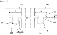
- FIG. 3 is a vertical sectional view of coupling portions of a first case and a second case according to the present invention.
- FIG. 3(a) shows the state in which ultrasonic welding is being performed in the state in which the first case 100 and the second case 200 are coupled to each other
- FIG. 3(b) shows the state in which ultrasonic welding has been completed.
- the battery pack case includes the first case 100 and the second case 200.
- a projecting portion 110 is formed on a coupling portion of the first case 100 at a middle part of the first case 100 in a thickness direction D thereof so as to project downwards therefrom, and a grooved portion 220 is formed in a coupling portion of the second case 200 at a middle part of the second case 200 in a thickness direction D thereof such that the projecting portion 110 is inserted into the grooved portion.
- the projecting portion 110 is inserted into the grooved portion 220, whereby the first case and the second case are primarily coupled to each other.
- the projecting portion 110 includes an energy director 150 configured to be melted by heat and a support portion 160 excluding the energy director 150.
- FIG. 3(a) shows the state in which ultrasonic welding is being performed, wherein half or more of the energy director 150 is melted.
- the separation space between the projecting portion 110 and the inner surface of the grooved portion 220 is fully filled with the melted energy director.
- the grooved portion 220 of the second case 200 is configured to have a structure in which opposite sides of a concave groove project.
- a uniform gap H is formed between the outside 111 of the projecting portion 110 of the first case and the outside 222 of the grooved portion 220 of the second case, since a support structure is formed at the first case 100 and the second case 200 according to the present invention, as shown in FIGS. 4 and 5 .
- the gap H is formed between the outside 111 of the projecting portion of the first case and the outside 222 of the grooved portion of the second case, as the coupling portions of the first case and the second case, along the entire outer peripheries thereof, whereby it is possible to solve a conventional problem in that burrs are generated on the coupling portions due to over-fusion of the battery case. Consequently, it is possible to remarkably reduce external defects.
- FIG. 4 is a perspective view of the first case according to the present invention
- FIG. 5 is a perspective view of the second case according to the present invention.
- a support structure is formed at the outer periphery of one open surface of the first case 100 and the outer periphery of one open surface of the second case 200 in order to form the gap H of FIG. 3 .
- the projecting portion 110 of the first case 100 includes an energy director 150 and a support portion 160, and a stopper recess 170 is formed in the projecting portion 110.
- a stopper rib 270 which is a support structure configured to maintain the gap H between the first case 100 and the second case 200, is formed in the grooved portion 220 of the second case 200.
- the stopper rib 270 is formed in the grooved portion 220 so as to project upwards, and performs a function of preventing the projecting portion of the first case 100 from being deeply coupled to the grooved portion even when the projecting portion is excessively melted.
- the stopper recess 170 is formed at the position of the projecting portion 110 corresponding to the stopper rib 270 such that the stopper rib 270 is mounted in the stopper recess 170.
- the support portion 160 must be provided at the part at which the stopper recess 170 is formed in order to completely seal the battery pack. Consequently, it is preferable for the depth a1 of the stopper recess to be less than the height a2 of the projecting portion.
- the energy director is melted such that the height of the energy director is reduced or removed in the state in which the stopper rib 270, which is formed so as to project, is disposed in the stopper recess 170.
- the stopper rib must be deeply inserted into the innermost side of the stopper recess in order to stably fix the first case and the second case to each other. Consequently, the depth of the stopper recess 170 may be greater than the height of the stopper rib 270 based on the state before the energy director is melted.
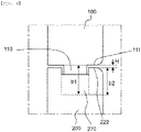
- FIG. 6 is a vertical sectional view showing the state in which the first case and the second case are fused to each other.
- the sum b1 of the height of the stopper rib 270 and the length of the projecting portion 110 at the part thereof at which the stopper recess is formed is greater than the depth b2 of the grooved portion of the second case 200 in the state in which the first case 100 and the second case 200 are coupled and thermally fused to each other. That is, in the state in which the first case and the second case are coupled and thermally fused to each other, the lower end of the support portion may be coupled to the stopper rib in contact therewith, and the sum of the height of the support portion and the height of the stopper rib may be greater than the depth b2 of the grooved portion of the second case.
- the support structure is formed at the first case and the second case such that a uniform gap H is formed between the outside 111 of the projecting portion of the first case and the outside 222 of the grooved portion of the second case in the state in which the first case and the second case are coupled and thermally fused to each other.
- the support structure may be constituted by a pair of a stopper recess and a stopper rib, and the support structure may be formed on at least one side of each of the outer peripheries of the first case and the second case at which the first case and the second case are coupled to each other. That is, one or more pairs of stopper recesses and stopper ribs may be formed on the one side of each of the outer peripheries.
- the support structure may be formed on the entire outer peripheries of the first case and the second case at which the first case and the second case are coupled to each other. That is, one or more support structures, each of which is constituted by a pair of a stopper recess and a stopper rib, may be formed on one side of each of the outer peripheries, and a plurality of support structures may be disposed at the entire outer peripheries.
- the support structures may be disposed so as to be spaced apart from each other by a predetermined distance, or may be disposed only on the straight outer periphery portions excluding corners of the outer peripheries.
- the battery pack case according to the present invention includes a support structure configured to prevent over-fusion between the first case and the second case as the result of excessively close coupling therebetween when the first case and the second case are thermally fused to each other in a state of being coupled to each other.
- the stopper recess of the first case is caught by the stopper rib of the second case by the provision of the support structure, whereby the first case is prevented from being further inserted into the grooved portion of the second case. Consequently, it is possible to prevent a melted battery case resin from flowing out over the side walls of the grooved portion, and therefore it is possible to prevent external defects at the coupling portion of the battery pack case.
- the battery pack case according to the present invention may be a case for battery packs that are used as energy sources for various kinds of devices, wherein a through-hole, through which electrode terminals of battery cells received in the battery pack case are withdrawn outwards, may be formed in the battery pack case.
- a structure configured to stably mount the battery pack case in various kinds of devices such as a hook structure, may be added to the battery pack case according to the present invention.
- the present invention relates to a battery pack case configured to receive a plurality of battery cells, the battery pack case including a first case and a second case coupled to each other through engagement therebetween, wherein a projecting portion is formed on a coupling portion of the first case at a middle part of the first case in a thickness direction thereof so as to project therefrom, a grooved portion is formed in a coupling portion of the second case at a middle part of the second case in a thickness direction thereof such that the projecting portion is inserted into the grooved portion, and a uniform gap is formed between the outside of the projecting portion of the first case and the outside of the grooved portion of the second case in the state in which the first case and the second case are coupled and thermally fused to each other, whereby the melted projecting portion is prevented from flowing out over the outside of the projecting portion of the first case and the outside of the grooved portion of the second case during ultrasonic welding, and therefore the present invention has industrial applicability.
Landscapes
- Engineering & Computer Science (AREA)
- Mechanical Engineering (AREA)
- Chemical & Material Sciences (AREA)
- Chemical Kinetics & Catalysis (AREA)
- Electrochemistry (AREA)
- General Chemical & Material Sciences (AREA)
- Battery Mounting, Suspending (AREA)
- Lining Or Joining Of Plastics Or The Like (AREA)
Abstract
Description
- This application claims the benefit of priority to
Korean Patent Application No. 2020-0157624 filed on November 23, 2020 - The present invention relates to a battery pack case including an over-fusion prevention structure. More particularly, the present invention relates to a battery pack case including an over-fusion prevention structure capable of preventing external defects from occurring on a coupling portion of the battery pack case due to over-fusion when ultrasonic welding is performed for coupling of the battery pack case.
- A battery pack constituted by secondary batteries connected to each other in series or in parallel is used as an energy source for medium- or large-sized devices, which require high output and high capacity. The battery pack may include a plurality of battery cells, a structure configured to perform electrical connection between the battery cells, a structure configured to control the operation of the battery cells, and a structure configured to adjusting heat generation/heat dissipation of the battery cells in a battery pack case, and coupling of the battery pack case is performed in the state in which the structures are received therein to manufacture the battery pack.
- As a coupling method of a battery pack case manufactured using a polymer resin, there is used a method of pressurizing the polymer resin in a molten state using frictional heat by ultrasonic vibration in order to achieve fusion. If a joint of the battery pack case is over-fused or pressing force is inaccurately controlled, the molten resin flows outwards, whereby burrs are generated.
-
FIG. 1 is a vertical sectional view of a coupling portion of a conventional battery pack case, andFIG. 2 is a front view of the coupling portion of the battery pack case ofFIG. 1 . - Referring to
FIGs. 1 and 2 , the battery pack case is constituted by afirst case 10 located above and asecond case 20 located below. A projectingportion 11 is formed on a coupling portion of thefirst case 10 at a middle part of the first case in a thickness direction D thereof so as to project downwards therefrom, and agrooved portion 22 is formed in a coupling portion of thesecond case 20 at a middle part of the second case in a thickness direction D thereof so as to be concave. The projectingportion 11 of thefirst case 10 is inserted into and fixed to thegrooved portion 22 of thesecond case 20, whereby the battery pack case is assembled. - The projecting
portion 11 includes anenergy director 15 formed at the end thereof such that the width of the energy director in the thickness direction D thereof is gradually decreased. When vibration is applied to thefirst case 10 and thesecond case 20, theenergy director 15 is melted in thegrooved portion 22 of thesecond case 20 while being vibrated, whereby thegrooved portion 22 is filled with the projectingportion 11. - At this time, if the first case is excessively pressed toward the second case in the state in which the
energy director 15 is melted, the energy director may be over-fused, whereby some of the melted energy director may flow out of the case. As a result,burrs 30 may be generated, as shown inFIG. 2 . -
FIG. 2 shows the state in which theburrs 30 are generated at the coupling portions of thefirst case 10 and thesecond case 20 due to over-fusion. In order to prevent generation of defects, such as burrs, it is important to maintain a uniform distance between the first case and the second case in a height direction thereof at the coupling portions of the first case and the second case. - In connection therewith, Patent Document 1 discloses a battery pack configured such that a battery pack case includes a front case and a rear case, a plurality of fusion protrusions made of a resin is formed along the edge of the rear case, i.e. the part of the rear case that contacts the front case, and outflow prevention recesses configured to prevent outflow of the fusion protrusions are formed along the edge of the front case at the region of the front case that contacts the fusion protrusions of the rear case.
- However, the outflow prevention recesses of Patent Document 1 have difficulty completely preventing the fusion protrusions from flowing out of the outflow prevention recesses when the fusion protrusions are melted. That is, time and force control is necessary when the front case and the rear case are coupled to each other, and, if the fusion protrusions flow out of the outflow prevention recesses in the state in which the fusion protrusions are melted, it is difficult to prevent external defects, such as the burrs of
FIG. 2 , from occurring between the battery cases. - Patent Document 2 discloses a vibration fusion structure between a resin case and a resin cover capable of preventing burrs generated when the resin case and the resin cover are fused to each other using vibration from leaking out into an inner space surrounded by the resin case and the resin cover, wherein projection portions projecting from the resin case and the resin cover are fused to each other by vibration to form a joint at fused portions of the resin case and the resin cover and wherein an inner burr concealment wall, an outer burr concealment wall, and a middle burr concealment wall are formed in order to prevent melting and flowing of the projecting portions.
- In Patent Document 2, when the fused portions are melted, it is possible to prevent the melted portions from flowing out of coupling portions of the resin case and the resin cover to a certain extent, since the plurality of concealment walls is formed. However, it is not possible to completely prevent burrs from flowing out of the coupling portions of the resin case and the resin cover, like Patent Document 1.
- Therefore, there is a need for a battery pack case having a structure capable of fundamentally preventing generation of external defects as the result of an energy director of a battery case melted by vibration heat flowing out of the battery case.
-
Korean Patent Application Publication No. 2004-0085478 -
Japanese Registered Patent Publication No. 4948004 - The present invention has been made in view of the above problems, and it is an object of the present invention to provide a battery pack case including an over-fusion prevention structure capable of preventing generation of burrs on a coupling portion of the battery pack case due to over-fusion of the battery pack case, thereby reducing external defects.
- In order to accomplish the above object, the present invention provides a battery pack case configured to receive a plurality of battery cells, the battery pack case including a first case and a second case coupled to each other through an engagement between the first case and the second case, wherein a projecting portion is formed on a coupling portion of the first case at a middle part of the first case in a thickness direction thereof so as to project therefrom, wherein a grooved portion is formed in a coupling portion of the second case at a middle part of the second case in a thickness direction thereof such that the projecting portion is inserted into the grooved portion, and wherein a uniform gap is formed between the outside of the projecting portion of the first case and the outside of the grooved portion of the second case in the state in which the first case and the second case are coupled and thermally fused to each other.
- A support structure configured to form the gap may be formed in the grooved portion of the second case.
- A stopper rib may be formed in the grooved portion of the second case as the support structure.
- A stopper recess may be formed at the position of the projecting portion of the first case corresponding to the stopper rib.
- The depth of the stopper recess may be less than the height of the projecting portion.
- The depth of the stopper recess may be greater than the height of the stopper rib based on the state before the projecting portion is melted.
- The projecting portion may include an energy director configured to be melted by thermal fusion and a support portion excluding the energy director.
- The sum of the height of the stopper rib and the length of the projecting portion at the part thereof at which the stopper recess is formed may be greater than the depth of the grooved portion of the second case in the state in which the first case and the second case are coupled and thermally fused to each other.
- A gap may be present between the projecting portion and an inner surface of the grooved portion before the first case and the second case are thermally fused to each other, and the projecting portion and the grooved portion may be fused to each other in the state in which the first case and the second case are thermally fused to each other.
- The support structure may be formed on at least one side of each of outer peripheries of the first case and the second case at which the first case and the second case are coupled to each other.
- The support structure may be formed on the entireties of outer peripheries of the first case and the second case at which the first case and the second case are coupled to each other.
- As is apparent from the above description, in a battery pack case according to the present invention, a support structure is formed at coupling portions of a first case and a second case, whereby it is possible to maintain a uniform coupling distance between the first case and the second case even when coupling force is excessively applied to the first case and the second case in the state in which a projecting portion of the first case is melted.
- Since the coupling distance between the first case and the second case is maintained uniform, as described above, it is possible to prevent generation of burrs due to over-fusion at the coupling portions of the first case and the second case, whereby it is possible to reduce an external defect rate.
-
-
FIG. 1 is a vertical sectional view of a coupling portion of a conventional battery pack case. -
FIG. 2 is a front view of the coupling portion of the battery pack case ofFIG. 1 . -
FIG. 3 is a vertical sectional view of coupling portions of a first case and a second case according to the present invention. -
FIG. 4 is a perspective view of the first case according to the present invention. -
FIG. 5 is a perspective view of the second case according to the present invention. -
FIG. 6 is a vertical sectional view showing the state in which the first case and the second case are fused to each other. - Now, preferred embodiments of the present invention will be described in detail with reference to the accompanying drawings such that the preferred embodiments of the present invention can be easily implemented by a person having ordinary skill in the art to which the present invention pertains. In describing the principle of operation of the preferred embodiments of the present invention in detail, however, a detailed description of known functions and configurations incorporated herein will be omitted when the same may obscure the subject matter of the present invention.
- In addition, the same reference numbers will be used throughout the drawings to refer to parts that perform similar functions or operations. In the case in which one part is said to be connected to another part throughout the specification, not only may the one part be directly connected to the other part, but also, the one part may be indirectly connected to the other part via a further part. In addition, that a certain element is included does not mean that other elements are excluded, but means that such elements may be further included unless mentioned otherwise.
- In addition, a description to embody elements through limitation or addition may be applied to all inventions, unless particularly restricted, and does not limit a specific invention.
- Also, in the description of the invention and the claims of the present application, singular forms are intended to include plural forms unless mentioned otherwise.
- Also, in the description of the invention and the claims of the present application, "or" includes "and" unless mentioned otherwise. Therefore, "including A or B" means three cases, namely, the case including A, the case including B, and the case including A and B.
- In addition, all numeric ranges include the lowest value, the highest value, and all intermediate values therebetween unless the context clearly indicates otherwise.
- An embodiment of the present invention will be described in detail with reference to the accompanying drawings.
- A battery pack case according to the present invention includes a first case and a second case, which are separated from each other. The first case and the second case have a structure in which the first case and the second case are coupled to each other through engagement therebetween.
- Specifically, a projecting portion is formed on a coupling portion of the first case at a middle part of the first case in a thickness direction thereof so as to project therefrom, and a grooved portion is formed in a coupling portion of the second case at a middle part of the second case in a thickness direction thereof such that the projecting portion is inserted into the grooved portion. Consequently, the projecting portion may be inserted into the grooved portion, whereby engagement therebetween may be achieved.
- In connection therewith,
FIG. 3 is a vertical sectional view of coupling portions of a first case and a second case according to the present invention. - Referring to
FIG. 3 , FIG. 3(a) shows the state in which ultrasonic welding is being performed in the state in which thefirst case 100 and thesecond case 200 are coupled to each other, and FIG. 3(b) shows the state in which ultrasonic welding has been completed. - The battery pack case includes the
first case 100 and thesecond case 200. A projectingportion 110 is formed on a coupling portion of thefirst case 100 at a middle part of thefirst case 100 in a thickness direction D thereof so as to project downwards therefrom, and agrooved portion 220 is formed in a coupling portion of thesecond case 200 at a middle part of thesecond case 200 in a thickness direction D thereof such that the projectingportion 110 is inserted into the grooved portion. The projectingportion 110 is inserted into thegrooved portion 220, whereby the first case and the second case are primarily coupled to each other. - When ultrasonic vibration is applied to the
first case 100 and thesecond case 200 in this state, frictional heat is generated at the interface between the projectingportion 110 of thefirst case 100 and thegrooved portion 220 of thesecond case 200, whereby the end of the projectingportion 110 is melted. That is, the projectingportion 110 includes anenergy director 150 configured to be melted by heat and asupport portion 160 excluding theenergy director 150. - A separation space is present between the projecting
portion 110 and the inner surface of thegrooved portion 220 before thefirst case 100 and thesecond case 200 are thermally fused to each other. FIG. 3(a) shows the state in which ultrasonic welding is being performed, wherein half or more of theenergy director 150 is melted. When thefirst case 100 and thesecond case 200 are pressed so as to be closer to each other while theenergy director 150 is melted, the separation space between the projectingportion 110 and the inner surface of thegrooved portion 220 is fully filled with the melted energy director. - The
grooved portion 220 of thesecond case 200 is configured to have a structure in which opposite sides of a concave groove project. When ultrasonic welding is performed in the state in which the projectingportion 110 is inserted into thegrooved portion 220, therefore, it is possible to prevent bending of the projecting portion and to maintain the projecting shape of the projecting portion in thegrooved portion 220. - Also, even in the state in which the
energy director 150 is melted by ultrasonic welding, a uniform gap H is formed between the outside 111 of the projectingportion 110 of the first case and the outside 222 of thegrooved portion 220 of the second case, since a support structure is formed at thefirst case 100 and thesecond case 200 according to the present invention, as shown inFIGS. 4 and5 . - As described above, the gap H is formed between the outside 111 of the projecting portion of the first case and the outside 222 of the grooved portion of the second case, as the coupling portions of the first case and the second case, along the entire outer peripheries thereof, whereby it is possible to solve a conventional problem in that burrs are generated on the coupling portions due to over-fusion of the battery case. Consequently, it is possible to remarkably reduce external defects.
-
FIG. 4 is a perspective view of the first case according to the present invention, andFIG. 5 is a perspective view of the second case according to the present invention. - Referring to
FIGS. 4 and5 , a support structure is formed at the outer periphery of one open surface of thefirst case 100 and the outer periphery of one open surface of thesecond case 200 in order to form the gap H ofFIG. 3 . - Specifically, the projecting
portion 110 of thefirst case 100 includes anenergy director 150 and asupport portion 160, and astopper recess 170 is formed in the projectingportion 110. - A
stopper rib 270, which is a support structure configured to maintain the gap H between thefirst case 100 and thesecond case 200, is formed in thegrooved portion 220 of thesecond case 200. Thestopper rib 270 is formed in thegrooved portion 220 so as to project upwards, and performs a function of preventing the projecting portion of thefirst case 100 from being deeply coupled to the grooved portion even when the projecting portion is excessively melted. - In consideration of the fact that ultrasonic welding must be performed in the state in which the projecting
portion 110 is deeply inserted into thegrooved portion 220 to a certain extent in order to achieve stable fusion, however, it is preferable for thestopper recess 170 to be formed at the position of the projectingportion 110 corresponding to thestopper rib 270 such that thestopper rib 270 is mounted in thestopper recess 170. - Also, in consideration of the fact that the
energy director 150 is melted and thegrooved portion 220 is filled with the meltedenergy director 150 in the state in which thestopper rib 270 is mounted in thestopper recess 170 in order to achieve sealing of the battery pack, thesupport portion 160 must be provided at the part at which thestopper recess 170 is formed in order to completely seal the battery pack. Consequently, it is preferable for the depth a1 of the stopper recess to be less than the height a2 of the projecting portion. - Meanwhile, the energy director is melted such that the height of the energy director is reduced or removed in the state in which the
stopper rib 270, which is formed so as to project, is disposed in thestopper recess 170. At this time, the stopper rib must be deeply inserted into the innermost side of the stopper recess in order to stably fix the first case and the second case to each other. Consequently, the depth of thestopper recess 170 may be greater than the height of thestopper rib 270 based on the state before the energy director is melted. -
FIG. 6 is a vertical sectional view showing the state in which the first case and the second case are fused to each other. - Referring to
FIG. 6 , the sum b1 of the height of thestopper rib 270 and the length of the projectingportion 110 at the part thereof at which the stopper recess is formed is greater than the depth b2 of the grooved portion of thesecond case 200 in the state in which thefirst case 100 and thesecond case 200 are coupled and thermally fused to each other. That is, in the state in which the first case and the second case are coupled and thermally fused to each other, the lower end of the support portion may be coupled to the stopper rib in contact therewith, and the sum of the height of the support portion and the height of the stopper rib may be greater than the depth b2 of the grooved portion of the second case. - The reason for this is that the support structure is formed at the first case and the second case such that a uniform gap H is formed between the outside 111 of the projecting portion of the first case and the outside 222 of the grooved portion of the second case in the state in which the first case and the second case are coupled and thermally fused to each other.
- In a concrete example, the support structure may be constituted by a pair of a stopper recess and a stopper rib, and the support structure may be formed on at least one side of each of the outer peripheries of the first case and the second case at which the first case and the second case are coupled to each other. That is, one or more pairs of stopper recesses and stopper ribs may be formed on the one side of each of the outer peripheries.
- Alternatively, the support structure may be formed on the entire outer peripheries of the first case and the second case at which the first case and the second case are coupled to each other. That is, one or more support structures, each of which is constituted by a pair of a stopper recess and a stopper rib, may be formed on one side of each of the outer peripheries, and a plurality of support structures may be disposed at the entire outer peripheries. The support structures may be disposed so as to be spaced apart from each other by a predetermined distance, or may be disposed only on the straight outer periphery portions excluding corners of the outer peripheries.
- As described above, the battery pack case according to the present invention includes a support structure configured to prevent over-fusion between the first case and the second case as the result of excessively close coupling therebetween when the first case and the second case are thermally fused to each other in a state of being coupled to each other. The stopper recess of the first case is caught by the stopper rib of the second case by the provision of the support structure, whereby the first case is prevented from being further inserted into the grooved portion of the second case. Consequently, it is possible to prevent a melted battery case resin from flowing out over the side walls of the grooved portion, and therefore it is possible to prevent external defects at the coupling portion of the battery pack case.
- Additionally, the battery pack case according to the present invention may be a case for battery packs that are used as energy sources for various kinds of devices, wherein a through-hole, through which electrode terminals of battery cells received in the battery pack case are withdrawn outwards, may be formed in the battery pack case.
- Alternatively, a structure configured to stably mount the battery pack case in various kinds of devices, such as a hook structure, may be added to the battery pack case according to the present invention.
- Those skilled in the art to which the present invention pertains will appreciate that various applications and modifications are possible within the category of the present invention based on the above description.
-
- 10, 100: First cases
- 11, 110: Projecting portions
- 15, 150: Energy directors
- 20, 200: Second cases
- 22, 220: Grooved portions
- 30: Burrs
- 111: Outside of projecting portion
- 160: Support portion
- 170: Stopper recess
- 222: Outside of grooved portion
- 270: Stopper rib
- a1: Depth of stopper recess
- a2: Height of projecting portion
- b1: Sum of height of stopper rib and length of projecting portion at part at which stopper recess is formed
- b2: Depth of grooved portion
- D: Thickness direction
- H: Gap
- The present invention relates to a battery pack case configured to receive a plurality of battery cells, the battery pack case including a first case and a second case coupled to each other through engagement therebetween, wherein a projecting portion is formed on a coupling portion of the first case at a middle part of the first case in a thickness direction thereof so as to project therefrom, a grooved portion is formed in a coupling portion of the second case at a middle part of the second case in a thickness direction thereof such that the projecting portion is inserted into the grooved portion, and a uniform gap is formed between the outside of the projecting portion of the first case and the outside of the grooved portion of the second case in the state in which the first case and the second case are coupled and thermally fused to each other, whereby the melted projecting portion is prevented from flowing out over the outside of the projecting portion of the first case and the outside of the grooved portion of the second case during ultrasonic welding, and therefore the present invention has industrial applicability.
Claims (11)
- A battery pack case configured to receive a plurality of battery cells, the battery pack case comprising:a first case and a second case coupled to each other through an engagement between the first case and the second case,wherein a projecting portion is formed on a coupling portion of the first case at a middle part of the first case in a thickness direction thereof so as to project therefrom,wherein a grooved portion is formed in a coupling portion of the second case at a middle part of the second case in a thickness direction thereof such that the projecting portion is inserted into the grooved portion, andwherein a uniform gap is formed between an outside of the projecting portion of the first case and an outside of the grooved portion of the second case in a state in which the first case and the second case are coupled and thermally fused to each other.
- The battery pack case according to claim 1, wherein a support structure configured to form the gap is formed in the grooved portion of the second case.
- The battery pack case according to claim 2, wherein a stopper rib is formed in the grooved portion of the second case as the support structure.
- The battery pack case according to claim 3, wherein a stopper recess is formed at a position of the projecting portion of the first case corresponding to the stopper rib.
- The battery pack case according to claim 4, wherein a depth of the stopper recess is less than a height of the projecting portion.
- The battery pack case according to claim 4, wherein a depth of the stopper recess is greater than a height of the stopper rib based on a state before the projecting portion is melted.
- The battery pack case according to claim 1, wherein the projecting portion comprises an energy director configured to be melted by thermal fusion and a support portion excluding the energy director.
- The battery pack case according to claim 3, wherein a sum of a height of the stopper rib and a length of the projecting portion at a part thereof at which the stopper recess is formed is greater than a depth of the grooved portion of the second case in a state in which the first case and the second case are coupled and thermally fused to each other.
- The battery pack case according to claim 1, wherein a gap is present between the projecting portion and an inner surface of the grooved portion before the first case and the second case are thermally fused to each other, and
wherein the projecting portion and the grooved portion are fused to each other in a state in which the first case and the second case are thermally fused to each other. - The battery pack case according to claim 2, wherein the support structure is formed on at least one side of each of outer peripheries of the first case and the second case at which the first case and the second case are coupled to each other.
- The battery pack case according to claim 2, wherein the support structure is formed on entireties of outer peripheries of the first case and the second case at which the first case and the second case are coupled to each other.
Applications Claiming Priority (2)
| Application Number | Priority Date | Filing Date | Title |
|---|---|---|---|
| KR1020200157624A KR102956903B1 (en) | 2020-11-23 | 2020-11-23 | Battery Pack Case Comprising Over-Fusion Preventing Structure |
| PCT/KR2021/017118 WO2022108398A1 (en) | 2020-11-23 | 2021-11-19 | Battery pack case comprising over-fusion prevention structure |
Publications (3)
| Publication Number | Publication Date |
|---|---|
| EP4113717A1 true EP4113717A1 (en) | 2023-01-04 |
| EP4113717A4 EP4113717A4 (en) | 2023-10-04 |
| EP4113717B1 EP4113717B1 (en) | 2025-09-03 |
Family
ID=81709490
Family Applications (1)
| Application Number | Title | Priority Date | Filing Date |
|---|---|---|---|
| EP21895165.5A Active EP4113717B1 (en) | 2020-11-23 | 2021-11-19 | Battery pack case including over-fusion prevention structure |
Country Status (8)
| Country | Link |
|---|---|
| US (1) | US12562424B2 (en) |
| EP (1) | EP4113717B1 (en) |
| JP (1) | JP7508172B2 (en) |
| KR (1) | KR102956903B1 (en) |
| CN (1) | CN115398727B (en) |
| ES (1) | ES3042286T3 (en) |
| HU (1) | HUE073231T2 (en) |
| WO (1) | WO2022108398A1 (en) |
Families Citing this family (1)
| Publication number | Priority date | Publication date | Assignee | Title |
|---|---|---|---|---|
| GB2627977A (en) * | 2023-03-10 | 2024-09-11 | Jaguar Land Rover Ltd | Battery cell housing |
Family Cites Families (16)
| Publication number | Priority date | Publication date | Assignee | Title |
|---|---|---|---|---|
| CN1198346C (en) | 2000-03-14 | 2005-04-20 | 松下电器产业株式会社 | Secondary battery, wire bonding method thereof, and battery power supply device using the same |
| JP2001313014A (en) | 2000-04-27 | 2001-11-09 | Sanyo Electric Co Ltd | Equipment case |
| JP4972823B2 (en) * | 2001-02-21 | 2012-07-11 | パナソニック株式会社 | Battery pack |
| JP4269638B2 (en) | 2002-10-22 | 2009-05-27 | 株式会社村田製作所 | Ultrasonic welding method of resin package |
| KR20040085478A (en) | 2003-03-31 | 2004-10-08 | (주) 프로-테크 | Structure of battery-pack case in a mobile phone |
| KR101075297B1 (en) | 2004-10-19 | 2011-10-19 | 삼성에스디아이 주식회사 | Battery pack case and mold for manufacturing battery case |
| JP4948004B2 (en) | 2006-03-16 | 2012-06-06 | 東京濾器株式会社 | Vibration welding structure between resin case and resin cover |
| JP5052850B2 (en) | 2006-09-21 | 2012-10-17 | 豊達電機(香港)有限公司 | Ultrasonic welding and joining method of speaker cabinet and speaker cabinet manufactured thereby |
| JP2009181830A (en) | 2008-01-31 | 2009-08-13 | Panasonic Corp | Battery pack manufacturing method and battery pack |
| WO2011096159A1 (en) | 2010-02-02 | 2011-08-11 | パナソニック株式会社 | Battery case and battery pack provided therewith |
| JP2011233461A (en) * | 2010-04-30 | 2011-11-17 | Shin Kobe Electric Mach Co Ltd | Box and battery case for lead acid storage battery using this box |
| KR101397028B1 (en) | 2012-09-13 | 2014-05-20 | 삼성에스디아이 주식회사 | Battery pack |
| KR20160124004A (en) | 2015-04-17 | 2016-10-26 | 타이코에이엠피 주식회사 | Battery package housing and manufacturing method thereof |
| JP2018171711A (en) * | 2017-03-31 | 2018-11-08 | 株式会社デンソー | Zygote |
| JP7005199B2 (en) * | 2017-07-14 | 2022-01-21 | 三洋電機株式会社 | Battery pack and its manufacturing method |
| KR102407165B1 (en) | 2019-01-03 | 2022-06-10 | 주식회사 엘지에너지솔루션 | Battery pack and apparatus for assembling battery pack |
-
2020
- 2020-11-23 KR KR1020200157624A patent/KR102956903B1/en active Active
-
2021
- 2021-11-19 WO PCT/KR2021/017118 patent/WO2022108398A1/en not_active Ceased
- 2021-11-19 JP JP2022564467A patent/JP7508172B2/en active Active
- 2021-11-19 CN CN202180028975.3A patent/CN115398727B/en active Active
- 2021-11-19 ES ES21895165T patent/ES3042286T3/en active Active
- 2021-11-19 EP EP21895165.5A patent/EP4113717B1/en active Active
- 2021-11-19 US US17/915,851 patent/US12562424B2/en active Active
- 2021-11-19 HU HUE21895165A patent/HUE073231T2/en unknown
Also Published As
| Publication number | Publication date |
|---|---|
| WO2022108398A1 (en) | 2022-05-27 |
| ES3042286T3 (en) | 2025-11-19 |
| JP2023523259A (en) | 2023-06-02 |
| KR102956903B1 (en) | 2026-04-23 |
| CN115398727A (en) | 2022-11-25 |
| EP4113717B1 (en) | 2025-09-03 |
| HUE073231T2 (en) | 2026-01-28 |
| EP4113717A4 (en) | 2023-10-04 |
| CN115398727B (en) | 2024-06-28 |
| JP7508172B2 (en) | 2024-07-01 |
| KR20220070742A (en) | 2022-05-31 |
| US20230155225A1 (en) | 2023-05-18 |
| US12562424B2 (en) | 2026-02-24 |
Similar Documents
| Publication | Publication Date | Title |
|---|---|---|
| JP4732462B2 (en) | Lock type battery pack | |
| JP5475206B1 (en) | Prismatic secondary battery | |
| EP3823059B1 (en) | Battery pack | |
| CN101523640A (en) | Battery and method of manufacturing battery | |
| EP1422770B1 (en) | Prismatic sealed battery | |
| JP5691998B2 (en) | Battery case | |
| US9029007B2 (en) | Rechargeable battery including first and second metallic plates coupled together and a cap assembly including an insulator | |
| US12562424B2 (en) | Battery pack case including over-fusion prevention structure | |
| JP2018055981A (en) | Secondary battery | |
| JP3806527B2 (en) | Electrical device case and method of manufacturing the same | |
| JP2021052020A (en) | Secondary battery and secondary battery assembly | |
| EP4274013A1 (en) | Waterproof battery pack case for preventing over-fusion | |
| JP5904659B2 (en) | Pack battery | |
| JP5879373B2 (en) | Prismatic secondary battery | |
| JP6331753B2 (en) | Battery case | |
| JP2013037858A (en) | Battery pack with non-conduction type breaker | |
| CN121713325A (en) | Power supply device | |
| JP6047676B2 (en) | Prismatic secondary battery | |
| JP2016122551A (en) | breaker | |
| CN120357102A (en) | Battery cover plate and battery | |
| JP2010262757A (en) | Battery pack |
Legal Events
| Date | Code | Title | Description |
|---|---|---|---|
| STAA | Information on the status of an ep patent application or granted ep patent |
Free format text: STATUS: THE INTERNATIONAL PUBLICATION HAS BEEN MADE |
|
| PUAI | Public reference made under article 153(3) epc to a published international application that has entered the european phase |
Free format text: ORIGINAL CODE: 0009012 |
|
| STAA | Information on the status of an ep patent application or granted ep patent |
Free format text: STATUS: REQUEST FOR EXAMINATION WAS MADE |
|
| 17P | Request for examination filed |
Effective date: 20220928 |
|
| AK | Designated contracting states |
Kind code of ref document: A1 Designated state(s): AL AT BE BG CH CY CZ DE DK EE ES FI FR GB GR HR HU IE IS IT LI LT LU LV MC MK MT NL NO PL PT RO RS SE SI SK SM TR |
|
| A4 | Supplementary search report drawn up and despatched |
Effective date: 20230901 |
|
| RIC1 | Information provided on ipc code assigned before grant |
Ipc: H01M 50/207 20210101ALI20230828BHEP Ipc: B29L 31/00 20060101ALI20230828BHEP Ipc: B29C 65/56 20060101ALI20230828BHEP Ipc: B29C 65/08 20060101ALI20230828BHEP Ipc: H01M 50/204 20210101AFI20230828BHEP |
|
| DAV | Request for validation of the european patent (deleted) | ||
| DAX | Request for extension of the european patent (deleted) | ||
| GRAP | Despatch of communication of intention to grant a patent |
Free format text: ORIGINAL CODE: EPIDOSNIGR1 |
|
| STAA | Information on the status of an ep patent application or granted ep patent |
Free format text: STATUS: GRANT OF PATENT IS INTENDED |
|
| RIC1 | Information provided on ipc code assigned before grant |
Ipc: H01M 50/207 20210101ALI20250422BHEP Ipc: B29L 31/00 20060101ALI20250422BHEP Ipc: B29C 65/56 20060101ALI20250422BHEP Ipc: B29C 65/08 20060101ALI20250422BHEP Ipc: H01M 50/204 20210101AFI20250422BHEP |
|
| INTG | Intention to grant announced |
Effective date: 20250507 |
|
| P01 | Opt-out of the competence of the unified patent court (upc) registered |
Free format text: CASE NUMBER: APP_26048/2025 Effective date: 20250602 |
|
| GRAS | Grant fee paid |
Free format text: ORIGINAL CODE: EPIDOSNIGR3 |
|
| GRAA | (expected) grant |
Free format text: ORIGINAL CODE: 0009210 |
|
| STAA | Information on the status of an ep patent application or granted ep patent |
Free format text: STATUS: THE PATENT HAS BEEN GRANTED |
|
| AK | Designated contracting states |
Kind code of ref document: B1 Designated state(s): AL AT BE BG CH CY CZ DE DK EE ES FI FR GB GR HR HU IE IS IT LI LT LU LV MC MK MT NL NO PL PT RO RS SE SI SK SM TR |
|
| REG | Reference to a national code |
Ref country code: CH Ref legal event code: EP |
|
| REG | Reference to a national code |
Ref country code: DE Ref legal event code: R096 Ref document number: 602021038037 Country of ref document: DE |
|
| REG | Reference to a national code |
Ref country code: IE Ref legal event code: FG4D |
|
| REG | Reference to a national code |
Ref country code: ES Ref legal event code: FG2A Ref document number: 3042286 Country of ref document: ES Kind code of ref document: T3 Effective date: 20251119 |
|
| PGFP | Annual fee paid to national office [announced via postgrant information from national office to epo] |
Ref country code: HU Payment date: 20251127 Year of fee payment: 5 |
|
| REG | Reference to a national code |
Ref country code: NL Ref legal event code: MP Effective date: 20250903 |
|
| PGFP | Annual fee paid to national office [announced via postgrant information from national office to epo] |
Ref country code: DE Payment date: 20251020 Year of fee payment: 5 |
|
| PGFP | Annual fee paid to national office [announced via postgrant information from national office to epo] |
Ref country code: GB Payment date: 20251023 Year of fee payment: 5 |
|
| PG25 | Lapsed in a contracting state [announced via postgrant information from national office to epo] |
Ref country code: NO Free format text: LAPSE BECAUSE OF FAILURE TO SUBMIT A TRANSLATION OF THE DESCRIPTION OR TO PAY THE FEE WITHIN THE PRESCRIBED TIME-LIMIT Effective date: 20251203 |
|
| REG | Reference to a national code |
Ref country code: LT Ref legal event code: MG9D |
|
| PGFP | Annual fee paid to national office [announced via postgrant information from national office to epo] |
Ref country code: AT Payment date: 20260113 Year of fee payment: 5 |
|
| PG25 | Lapsed in a contracting state [announced via postgrant information from national office to epo] |
Ref country code: FI Free format text: LAPSE BECAUSE OF FAILURE TO SUBMIT A TRANSLATION OF THE DESCRIPTION OR TO PAY THE FEE WITHIN THE PRESCRIBED TIME-LIMIT Effective date: 20250903 |
|
| PG25 | Lapsed in a contracting state [announced via postgrant information from national office to epo] |
Ref country code: HR Free format text: LAPSE BECAUSE OF FAILURE TO SUBMIT A TRANSLATION OF THE DESCRIPTION OR TO PAY THE FEE WITHIN THE PRESCRIBED TIME-LIMIT Effective date: 20250903 |
|
| PGFP | Annual fee paid to national office [announced via postgrant information from national office to epo] |
Ref country code: FR Payment date: 20251021 Year of fee payment: 5 |
|
| PG25 | Lapsed in a contracting state [announced via postgrant information from national office to epo] |
Ref country code: GR Free format text: LAPSE BECAUSE OF FAILURE TO SUBMIT A TRANSLATION OF THE DESCRIPTION OR TO PAY THE FEE WITHIN THE PRESCRIBED TIME-LIMIT Effective date: 20251204 |
|
| PGFP | Annual fee paid to national office [announced via postgrant information from national office to epo] |
Ref country code: BE Payment date: 20251020 Year of fee payment: 5 |
|
| PG25 | Lapsed in a contracting state [announced via postgrant information from national office to epo] |
Ref country code: SE Free format text: LAPSE BECAUSE OF FAILURE TO SUBMIT A TRANSLATION OF THE DESCRIPTION OR TO PAY THE FEE WITHIN THE PRESCRIBED TIME-LIMIT Effective date: 20250903 |
|
| PG25 | Lapsed in a contracting state [announced via postgrant information from national office to epo] |
Ref country code: LV Free format text: LAPSE BECAUSE OF FAILURE TO SUBMIT A TRANSLATION OF THE DESCRIPTION OR TO PAY THE FEE WITHIN THE PRESCRIBED TIME-LIMIT Effective date: 20250903 |
|
| PG25 | Lapsed in a contracting state [announced via postgrant information from national office to epo] |
Ref country code: BG Free format text: LAPSE BECAUSE OF FAILURE TO SUBMIT A TRANSLATION OF THE DESCRIPTION OR TO PAY THE FEE WITHIN THE PRESCRIBED TIME-LIMIT Effective date: 20250903 Ref country code: PL Free format text: LAPSE BECAUSE OF FAILURE TO SUBMIT A TRANSLATION OF THE DESCRIPTION OR TO PAY THE FEE WITHIN THE PRESCRIBED TIME-LIMIT Effective date: 20250903 |
|
| PG25 | Lapsed in a contracting state [announced via postgrant information from national office to epo] |
Ref country code: RS Free format text: LAPSE BECAUSE OF FAILURE TO SUBMIT A TRANSLATION OF THE DESCRIPTION OR TO PAY THE FEE WITHIN THE PRESCRIBED TIME-LIMIT Effective date: 20251203 |
|
| REG | Reference to a national code |
Ref country code: HU Ref legal event code: AG4A Ref document number: E073231 Country of ref document: HU |
|
| PGFP | Annual fee paid to national office [announced via postgrant information from national office to epo] |
Ref country code: ES Payment date: 20251215 Year of fee payment: 5 |
|
| REG | Reference to a national code |
Ref country code: AT Ref legal event code: MK05 Ref document number: 1834276 Country of ref document: AT Kind code of ref document: T Effective date: 20250903 |
|
| PG25 | Lapsed in a contracting state [announced via postgrant information from national office to epo] |
Ref country code: NL Free format text: LAPSE BECAUSE OF FAILURE TO SUBMIT A TRANSLATION OF THE DESCRIPTION OR TO PAY THE FEE WITHIN THE PRESCRIBED TIME-LIMIT Effective date: 20250903 |
|
| PG25 | Lapsed in a contracting state [announced via postgrant information from national office to epo] |
Ref country code: SM Free format text: LAPSE BECAUSE OF FAILURE TO SUBMIT A TRANSLATION OF THE DESCRIPTION OR TO PAY THE FEE WITHIN THE PRESCRIBED TIME-LIMIT Effective date: 20250903 |
|
| PG25 | Lapsed in a contracting state [announced via postgrant information from national office to epo] |
Ref country code: AT Free format text: LAPSE BECAUSE OF FAILURE TO SUBMIT A TRANSLATION OF THE DESCRIPTION OR TO PAY THE FEE WITHIN THE PRESCRIBED TIME-LIMIT Effective date: 20250903 |
|
| PG25 | Lapsed in a contracting state [announced via postgrant information from national office to epo] |
Ref country code: RO Free format text: LAPSE BECAUSE OF FAILURE TO SUBMIT A TRANSLATION OF THE DESCRIPTION OR TO PAY THE FEE WITHIN THE PRESCRIBED TIME-LIMIT Effective date: 20250903 Ref country code: IT Free format text: LAPSE BECAUSE OF FAILURE TO SUBMIT A TRANSLATION OF THE DESCRIPTION OR TO PAY THE FEE WITHIN THE PRESCRIBED TIME-LIMIT Effective date: 20250903 |
|
| PG25 | Lapsed in a contracting state [announced via postgrant information from national office to epo] |
Ref country code: IS Free format text: LAPSE BECAUSE OF FAILURE TO SUBMIT A TRANSLATION OF THE DESCRIPTION OR TO PAY THE FEE WITHIN THE PRESCRIBED TIME-LIMIT Effective date: 20260103 |
|
| PG25 | Lapsed in a contracting state [announced via postgrant information from national office to epo] |
Ref country code: PT Free format text: LAPSE BECAUSE OF FAILURE TO SUBMIT A TRANSLATION OF THE DESCRIPTION OR TO PAY THE FEE WITHIN THE PRESCRIBED TIME-LIMIT Effective date: 20260105 Ref country code: CZ Free format text: LAPSE BECAUSE OF FAILURE TO SUBMIT A TRANSLATION OF THE DESCRIPTION OR TO PAY THE FEE WITHIN THE PRESCRIBED TIME-LIMIT Effective date: 20250903 |
|
| PG25 | Lapsed in a contracting state [announced via postgrant information from national office to epo] |
Ref country code: EE Free format text: LAPSE BECAUSE OF FAILURE TO SUBMIT A TRANSLATION OF THE DESCRIPTION OR TO PAY THE FEE WITHIN THE PRESCRIBED TIME-LIMIT Effective date: 20250903 Ref country code: SK Free format text: LAPSE BECAUSE OF FAILURE TO SUBMIT A TRANSLATION OF THE DESCRIPTION OR TO PAY THE FEE WITHIN THE PRESCRIBED TIME-LIMIT Effective date: 20250903 |