EP4113708A1 - Battery pack and electrical device - Google Patents
Battery pack and electrical device Download PDFInfo
- Publication number
- EP4113708A1 EP4113708A1 EP22181075.7A EP22181075A EP4113708A1 EP 4113708 A1 EP4113708 A1 EP 4113708A1 EP 22181075 A EP22181075 A EP 22181075A EP 4113708 A1 EP4113708 A1 EP 4113708A1
- Authority
- EP
- European Patent Office
- Prior art keywords
- cell
- sealing part
- disposed
- battery pack
- structural member
- Prior art date
- Legal status (The legal status is an assumption and is not a legal conclusion. Google has not performed a legal analysis and makes no representation as to the accuracy of the status listed.)
- Pending
Links
Images


Classifications
-
- H—ELECTRICITY
- H01—ELECTRIC ELEMENTS
- H01M—PROCESSES OR MEANS, e.g. BATTERIES, FOR THE DIRECT CONVERSION OF CHEMICAL ENERGY INTO ELECTRICAL ENERGY
- H01M50/00—Constructional details or processes of manufacture of the non-active parts of electrochemical cells other than fuel cells, e.g. hybrid cells
- H01M50/10—Primary casings, jackets or wrappings of a single cell or a single battery
- H01M50/102—Primary casings, jackets or wrappings of a single cell or a single battery characterised by their shape or physical structure
- H01M50/105—Pouches or flexible bags
-
- H—ELECTRICITY
- H01—ELECTRIC ELEMENTS
- H01M—PROCESSES OR MEANS, e.g. BATTERIES, FOR THE DIRECT CONVERSION OF CHEMICAL ENERGY INTO ELECTRICAL ENERGY
- H01M50/00—Constructional details or processes of manufacture of the non-active parts of electrochemical cells other than fuel cells, e.g. hybrid cells
- H01M50/50—Current conducting connections for cells or batteries
- H01M50/572—Means for preventing undesired use or discharge
- H01M50/584—Means for preventing undesired use or discharge for preventing incorrect connections inside or outside the batteries
- H01M50/586—Means for preventing undesired use or discharge for preventing incorrect connections inside or outside the batteries inside the batteries, e.g. incorrect connections of electrodes
-
- H—ELECTRICITY
- H01—ELECTRIC ELEMENTS
- H01M—PROCESSES OR MEANS, e.g. BATTERIES, FOR THE DIRECT CONVERSION OF CHEMICAL ENERGY INTO ELECTRICAL ENERGY
- H01M50/00—Constructional details or processes of manufacture of the non-active parts of electrochemical cells other than fuel cells, e.g. hybrid cells
- H01M50/10—Primary casings, jackets or wrappings of a single cell or a single battery
- H01M50/183—Sealing members
- H01M50/186—Sealing members characterised by the disposition of the sealing members
-
- H—ELECTRICITY
- H01—ELECTRIC ELEMENTS
- H01M—PROCESSES OR MEANS, e.g. BATTERIES, FOR THE DIRECT CONVERSION OF CHEMICAL ENERGY INTO ELECTRICAL ENERGY
- H01M50/00—Constructional details or processes of manufacture of the non-active parts of electrochemical cells other than fuel cells, e.g. hybrid cells
- H01M50/20—Mountings; Secondary casings or frames; Racks, modules or packs; Suspension devices; Shock absorbers; Transport or carrying devices; Holders
- H01M50/204—Racks, modules or packs for multiple batteries or multiple cells
- H01M50/207—Racks, modules or packs for multiple batteries or multiple cells characterised by their shape
- H01M50/211—Racks, modules or packs for multiple batteries or multiple cells characterised by their shape adapted for pouch cells
-
- H—ELECTRICITY
- H01—ELECTRIC ELEMENTS
- H01M—PROCESSES OR MEANS, e.g. BATTERIES, FOR THE DIRECT CONVERSION OF CHEMICAL ENERGY INTO ELECTRICAL ENERGY
- H01M50/00—Constructional details or processes of manufacture of the non-active parts of electrochemical cells other than fuel cells, e.g. hybrid cells
- H01M50/20—Mountings; Secondary casings or frames; Racks, modules or packs; Suspension devices; Shock absorbers; Transport or carrying devices; Holders
- H01M50/233—Mountings; Secondary casings or frames; Racks, modules or packs; Suspension devices; Shock absorbers; Transport or carrying devices; Holders characterised by physical properties of casings or racks, e.g. dimensions
-
- H—ELECTRICITY
- H01—ELECTRIC ELEMENTS
- H01M—PROCESSES OR MEANS, e.g. BATTERIES, FOR THE DIRECT CONVERSION OF CHEMICAL ENERGY INTO ELECTRICAL ENERGY
- H01M50/00—Constructional details or processes of manufacture of the non-active parts of electrochemical cells other than fuel cells, e.g. hybrid cells
- H01M50/20—Mountings; Secondary casings or frames; Racks, modules or packs; Suspension devices; Shock absorbers; Transport or carrying devices; Holders
- H01M50/249—Mountings; Secondary casings or frames; Racks, modules or packs; Suspension devices; Shock absorbers; Transport or carrying devices; Holders specially adapted for aircraft or vehicles, e.g. cars or trains
-
- H—ELECTRICITY
- H01—ELECTRIC ELEMENTS
- H01M—PROCESSES OR MEANS, e.g. BATTERIES, FOR THE DIRECT CONVERSION OF CHEMICAL ENERGY INTO ELECTRICAL ENERGY
- H01M50/00—Constructional details or processes of manufacture of the non-active parts of electrochemical cells other than fuel cells, e.g. hybrid cells
- H01M50/20—Mountings; Secondary casings or frames; Racks, modules or packs; Suspension devices; Shock absorbers; Transport or carrying devices; Holders
- H01M50/251—Mountings; Secondary casings or frames; Racks, modules or packs; Suspension devices; Shock absorbers; Transport or carrying devices; Holders specially adapted for stationary devices, e.g. power plant buffering or backup power supplies
-
- H—ELECTRICITY
- H01—ELECTRIC ELEMENTS
- H01M—PROCESSES OR MEANS, e.g. BATTERIES, FOR THE DIRECT CONVERSION OF CHEMICAL ENERGY INTO ELECTRICAL ENERGY
- H01M50/00—Constructional details or processes of manufacture of the non-active parts of electrochemical cells other than fuel cells, e.g. hybrid cells
- H01M50/20—Mountings; Secondary casings or frames; Racks, modules or packs; Suspension devices; Shock absorbers; Transport or carrying devices; Holders
- H01M50/289—Mountings; Secondary casings or frames; Racks, modules or packs; Suspension devices; Shock absorbers; Transport or carrying devices; Holders characterised by spacing elements or positioning means within frames, racks or packs
- H01M50/291—Mountings; Secondary casings or frames; Racks, modules or packs; Suspension devices; Shock absorbers; Transport or carrying devices; Holders characterised by spacing elements or positioning means within frames, racks or packs characterised by their shape
-
- H—ELECTRICITY
- H01—ELECTRIC ELEMENTS
- H01M—PROCESSES OR MEANS, e.g. BATTERIES, FOR THE DIRECT CONVERSION OF CHEMICAL ENERGY INTO ELECTRICAL ENERGY
- H01M50/00—Constructional details or processes of manufacture of the non-active parts of electrochemical cells other than fuel cells, e.g. hybrid cells
- H01M50/50—Current conducting connections for cells or batteries
- H01M50/571—Methods or arrangements for affording protection against corrosion; Selection of materials therefor
-
- H—ELECTRICITY
- H01—ELECTRIC ELEMENTS
- H01M—PROCESSES OR MEANS, e.g. BATTERIES, FOR THE DIRECT CONVERSION OF CHEMICAL ENERGY INTO ELECTRICAL ENERGY
- H01M2220/00—Batteries for particular applications
- H01M2220/10—Batteries in stationary systems, e.g. emergency power source in plant
-
- H—ELECTRICITY
- H01—ELECTRIC ELEMENTS
- H01M—PROCESSES OR MEANS, e.g. BATTERIES, FOR THE DIRECT CONVERSION OF CHEMICAL ENERGY INTO ELECTRICAL ENERGY
- H01M2220/00—Batteries for particular applications
- H01M2220/20—Batteries in motive systems, e.g. vehicle, ship, plane
-
- Y—GENERAL TAGGING OF NEW TECHNOLOGICAL DEVELOPMENTS; GENERAL TAGGING OF CROSS-SECTIONAL TECHNOLOGIES SPANNING OVER SEVERAL SECTIONS OF THE IPC; TECHNICAL SUBJECTS COVERED BY FORMER USPC CROSS-REFERENCE ART COLLECTIONS [XRACs] AND DIGESTS
- Y02—TECHNOLOGIES OR APPLICATIONS FOR MITIGATION OR ADAPTATION AGAINST CLIMATE CHANGE
- Y02E—REDUCTION OF GREENHOUSE GAS [GHG] EMISSIONS, RELATED TO ENERGY GENERATION, TRANSMISSION OR DISTRIBUTION
- Y02E60/00—Enabling technologies; Technologies with a potential or indirect contribution to GHG emissions mitigation
- Y02E60/10—Energy storage using batteries
Definitions
- the present application relates to the technical field of batteries, in particular to a battery pack and an electrical device.
- embodiments of the present application provide a battery pack and an electrical device for improving the problem of electrochemical corrosion caused by the connection of side seals of adjacent cells.
- embodiments of the present application provide a battery pack including a plurality of cells and a first structural member.
- the plurality of cells are stacked in a first direction, and the cells include an electrode assembly, a cell case, and a tab.
- the tab is connected to the electrode assembly and is extends out from the cell case.
- the cell case includes an accommodation portion for accommodating the electrode assembly and sealing parts extending outward from a periphery of the accommodation portion.
- the sealing parts include a first sealing part, a second sealing part and a third sealing part.
- the tab extends out of the cell case from the first sealing parts.
- the second sealing part is arranged on either of opposite sides of the accommodation portion in a second direction.
- the third sealing part extends from the second sealing part and connects the first sealing part and the second sealing part.
- a plurality of cells include a first cell and a second cell adjacent to each other.
- the third sealing part of the first cell is disposed oriented towards the third sealing part of the second cell, and the third sealing part of the second cell is disposed oriented toward the third sealing part of the first cell.
- the first structural member is made of an insulating material. The first structural member is disposed between the third sealing part of the first cell and the third sealing part of the adjacent second cell in the first direction.
- the first structural member separates the aluminum-plastic film of the first cell and the aluminum-plastic film of the adjacent second cell, thereby limiting the electronic circulation loop between the aluminum-plastic film of one of the first and second cells and the negative electrode of the other, improving electrochemical corrosion, and being beneficial to improving the safety performance of the cells and the battery pack.
- the battery pack also includes a housing for accommodating a plurality of cells, the housing includes a first wall, a second wall and a plurality of side walls, the first wall and the second wall are disposed opposite to each other in a third direction, the first structural member is disposed on the first wall, and the first structural member extends into the space between the third sealing part of the first cell and the third sealing part of the adjacent second cell in the second direction.
- the first structural member includes a first part disposed between the third sealing part of the first cell and the third sealing part of the adjacent second cell in the first direction, and a second part disposed between the first sealing part of the first cell and the first sealing part of the adjacent second cell.
- the first part and the second part as a whole are insulating members of a plate-like structure having a smaller thickness, which is beneficial for the first structural member to enter a position between the first cell and the adjacent second cell in a scenario where the first wall and the side walls are assembled.
- an orthographic projection of the third sealing part is located in an orthographic projection of the first part, which is beneficial for the first part to completely isolate the third sealing part of the first cell from the third sealing part of the adjacent second cell, thereby improving the isolation effect.
- a length of a portion that is of the first part and disposed between the third sealing parts is H1
- a length of a portion that is of the second part and disposed between the first sealing parts is H2, where H1 is less than H2.
- the second part is first extended to a position between the first sealing part of the first cell and the first sealing part of the adjacent second cell to implement preliminary positioning, which is beneficial for the first part to enter a position between the third sealing part of the first cell and the third sealing part of the adjacent second cell.
- a length of the third sealing part is H0, satisfying: H1 ⁇ 5% of ⁇ H0, which can reduce the contact between adjacent third sealing parts during manufacture or transportation.
- the first structural member also includes a third part for connecting the first part and the second part, and a side that is of the third part and oriented toward the cell is provided with an inclined surface, and the inclined surface is at an acute angle to the second direction.
- the inclined surface is beneficial for the first part to be guided into a position between the third sealing part of the first cell and the third sealing part of the adjacent second cell.
- the first wall includes a plurality of side plates forming a receiving space, the first structural member is arranged in the receiving space, and the first part is connected with the side plates.
- the plurality of cells further include a third cell disposed adjacent to the second cell, the third sealing part of the third cell is disposed opposite to the third sealing part of the second cell, the battery pack also includes a second structural member disposed on the first wall, in the first direction, the second structural member is disposed between a sealing part joint of the second cell and a sealing part joint of the third cell, and the sealing part joint is a joint of the first sealing part and the third sealing part.
- the second structural member can separate the aluminum-plastic film of the cell case in the second cell and the third cell to improve electrochemical corrosion.
- the first structural member and the second structural member can be an integrally formed insulating plate, the first structural member and the second structural member are arranged at intervals in turn in the first direction, a through hole is provided between the adjacent first and second structural members, and the tab of the cell passes through the through hole and extends out of the first wall.
- the through hole may be beneficial to the rapid heat dissipation of the cell.
- the plurality of side walls include a first side wall and a second side wall opposite to each other in a second direction, and the first structural member is provided in at least one of the first side wall and the second side wall.
- the cell case includes an aluminum-plastic film.
- a through hole is disposed between the adjacent first and second structural members, and the tab passes through the through hole and extends to the outside of the housing.
- the second structural member includes a fourth part disposed between the sealing part joint of the second cell and a sealing part joint of the third cell in the first direction and a fifth part disposed between the first sealing part of the second cell and the first sealing part of the third cell.
- an orthographic projection of the sealing part joint is located in an orthographic projection of the fourth part in the first direction.
- first structural member and the second structural member each include a convex portion including an inclined surface, and the inclined surface is at an acute angle to the third direction.
- a length of the convex portion does not exceed the length of the portion that is of the second part and disposed between the first sealing parts in the third direction, so as to guide the tab during an assembly process and facilitate passage of the tab through the through hole.
- the plurality of cells are divided into a plurality of columns, each column of cells including a plurality of groups, each group including a first cell and a second cell.
- the housing is provided with a separator, and two adjacent columns of cells are separated by the separator.
- the separator can be used to separate the aluminum-plastic films of two adjacent columns of cells and improve electrochemical corrosion.
- an orthographic projection of a portion that is of the first part and disposed between the adjacent third sealing parts is located in the orthographic projection of the first sealing part in the first direction.
- the first structural member is made of an insulating material, such as plastic.
- the second structural member is made of an insulating material, such as plastic.
- embodiments of the present application provide an electrical device including a load and a battery pack of any one of the above, the battery pack supplying power to the load.
- an insulating member is disposed between the side sealing parts of the adjacent cells, and the aluminum-plastic films of the adjacent cells are separated by the insulating member, so as to limit the electronic circulation loop between the aluminum-plastic film and the negative electrode, thereby improving electrochemical corrosion and improving the safety performance of the cells and the battery pack.
- the battery pack includes but is not limited to all kinds of primary batteries, secondary batteries, fuel batteries, solar batteries and capacitor (e.g., super capacitor) batteries.
- the battery pack may preferably be a lithium secondary battery including but not limited to a lithium metal secondary battery, a lithium ion secondary battery, a lithium polymer secondary battery and a lithium ion polymer secondary battery. Any cell in the battery pack includes, but is not limited to, soft pack cells.
- a battery pack 1 includes a cell module 10 and a first structural member 121.
- the cell module 10 includes a plurality of cells 11 stacked in the first direction x.
- the cell 11 includes an electrode assembly (not shown), a cell case 12, and a tab 13.
- the tab 13 is connected to the electrode assembly and is led out from the cell case 12.
- the first structural member 121 is made of an insulating material.
- the first structural member 121 is made of an insulating material such as plastic.
- an outer surface of the first structural member 121 is made of an insulating material.
- the cell case 12 includes an accommodation portion 12a for accommodating an electrode assembly (not shown), and a sealing part 12b extending outward from a periphery of the accommodation portion 12a.
- the sealing part 12b includes a first sealing part 12c, a second sealing part 12d and a third sealing part 12e.
- the tab 13 extends out of the cell case 12 from the first sealing part 12c.
- the second sealing part 12d is arranged on opposite sides of the accommodation portion 12a in a second direction y.
- the third sealing part 12e extends from the second sealing part 12d and connects the first sealing part 12c and the second sealing part 12d.
- the second direction y is perpendicular to the first direction x.
- the plurality of cells 11 may be arranged in such a manner that two adjacent cells 11 are grouped together, and the two cells 11 include a first cell 111 and a second cell 112.
- the third sealing part 12e of the first cell 111 is provided on a side of the first sealing part 12c of the first cell 11 close to the second cell 112, and the third sealing part 12e of the second cell 112 is provided on a side of the first sealing part 12c of the second cell 112 close to the first cell 111.
- the third sealing part 12e of the first cell 111 is disposed oriented toward the third sealing part 12e of the second cell 112, and the third sealing part 12e of the second cell 112 is disposed oriented toward the third sealing part 12e of the first cell 111.
- the first structural member 121 is disposed between the third sealing part 12e of the first cell 111 and the third sealing part 12e of the second cell 112 in the first direction x.
- the cell case 12 includes an aluminum-plastic film, and the first structural member 121 can be used to separate the aluminum-plastic films of the first cell 111 and the second cell 112, thereby limiting the electronic circulation loop between the aluminum-plastic film of one of the first cell 111 and the second cell 112 and the negative electrode of the other, improving electrochemical corrosion, and being beneficial to improving the safety performance of the cell 11 and the battery pack 1.
- a plurality of cells 11 may be connected in series or in parallel, to form an effective power supply and/or charging unit of the battery pack 1.
- the number of cells 11 can be determined according to the power demand.
- the tabs 13 of the plurality of cells 11 may be provided on the same side of the battery pack 1, where the tabs 12 of the first cell 111 and the second cell 112 are also provided on the same side of the battery pack 1.
- the cell 11 may also include an electrolyte or the like provided in the accommodation portion 12a.
- the electrode assembly includes a positive plate and a negative plate, and an insulating film disposed there between.
- the electrode assembly can be formed by winding or stacking a plurality of plates.
- One end of the tab 13 extends into the cell case 12 and is electrically connected with the plates of corresponding polarity.
- the other end of the tab 13 extends out from the cell case 12.
- the tab 13 includes a first tab 13a which is a negative tab and a second tab 13b which is a positive tab.
- the first tab 13a is electrically connected with the negative plate and extends from inside to outside of the cell case 12, and the second tab 13b is electrically connected with the positive plate and extends from inside to outside of the cell case 12.
- the first tab 13a may be a positive tab and the second tab 13b may be a negative tab.
- the configuration of the tab 13 of the present application is described in some instances herein by taking one of them as an example.
- the cell case 12 may be used to form a shape of the cell 11 and may also be used to define an external appearance of the cell 11. Internal elements such as the electrode assembly and electrolyte are accommodated in the accommodating portion 12a, and these internal elements are protected by the cell case 12, thereby improving the protection effect and safety of the cell 11.
- the sealing part 12b can be used for sealing and restricting leakage of electrolyte from an end portion and entry of impurities such as water and oxygen outside the cell case 12 into the accommodating portion 12a.
- the first sealing part 12c may be used to seal a joint of the cell case 12 and the tab 13.
- the battery pack 1 further includes a housing 30 housing a plurality of cells 11, and the cell module 10 is generally rectangular as a whole.
- the housing 30 includes a first wall 31, a second wall 32 and four side walls, and the four side walls include a first side wall 331, a second side wall 332, a third side wall 333 and a fourth side wall 334.
- the first wall 31 is disposed adjacent to the tab 13 of the cell 11, and the first wall 31 and the second wall 32 are disposed opposite to each other in a third direction z.
- the four side walls are connected between the first wall 121 and the second wall 122, the first side wall 331 and the second side wall 332 are disposed opposite to each other in the second direction y, the third side wall 333 and the fourth side wall 334 are disposed opposite to each other in the first direction x, the second direction y is perpendicular to a plane where the first direction x and the third direction z lie, and the first direction x may be perpendicular to the third direction z.
- the second wall 32 and the four side walls may be an integrally formed structural member, and the first wall 31 is detachably connected to the side walls to receive and protect the cell module 10.
- the third side wall 333 and the fourth side wall 334 are provided with protrusions 33a
- the first wall 31 is provided with sockets 31a on both side edges in the first direction x
- the protrusions 33a are inserted into the corresponding sockets 31a, so that the first wall 331 can be mounted and fixed to the side walls to form a receiving cavity 30a.
- the number of the sockets 31a and the protrusions 33a may be plural, which facilitates enhancing the stability of the structural connection. It should be understood that the number of sockets 31a and protrusions 33a shown in FIGS. 1 to 3 are shown by example only.
- a plurality of cells 11 may be disposed in the housing 30 in a predetermined manner, for example, the plurality of cells 11 are divided into a plurality of columns, each column of cells 11 including a plurality of groups, each group including a first cell 111 and a second cell 112.
- the housing 30 is provided with a separator 30b, and two adjacent columns of cells 11 are separated by the separator 30b.
- the separator 30b includes an insulating member including an insulating material, and the separator 30b can be used to separate the aluminum-plastic films of two adjacent columns of cells 11 to improve electrochemical corrosion.
- the first structural member 121 is provided on the first wall 31 and extends to a position between the third sealing part 12e of the first cell 111 and the third sealing part 12e of the adjacent second cell 112 in the third direction z.
- the first structural member 121 includes a first part 121a and a second part 121b.
- the first part 121a is disposed between a third sealing part 12e of the first cell 111 and the third sealing part 12e of the adjacent second cell 112.
- the second part 121b is disposed between the first sealing part 12c of the first cell 111 and the first sealing part 12c of the adjacent second cell 112.
- the first structural member 121 includes two first parts 121a with the second part 121b disposed there between.
- the first part 121a and the second part 121b are insulating members of a plate-like structure, which facilitates the entry of the first structural member 121 into a position between the first cell 111 and the second cell 112 in a scenario where the first wall 31 is assembled with the side walls.
- an orthographic projection of the third sealing part 12e is at least partially located in an orthographic projection of the first part 121a, which is beneficial for the first part 121a to isolate the third sealing part 12e of the first cell 111 from the third sealing part 12e of the adjacent second cell 112, thereby improving the isolation effect and improving electrochemical corrosion.
- a length of a portion that is of the first part 121a and disposed between the third sealing parts 12e is H1
- a length of a portion that is of the second part 121b and disposed between the first sealing parts 12c is H2, where H1 is less than H2.
- the second part 121b is first extended to a position between the first sealing part 12c of the first cell 111 and the first sealing part 12c of the adjacent second cell 112 to implement preliminary positioning, which is beneficial for the first part 121a to enter a position between the third sealing part 12e of the first cell 111 and the third sealing part 12e of the adjacent second cell 112.
- an orthographic projection of a portion that is of the first part 121a and disposed between the third sealing parts 12e is located in the orthographic projection of the first sealing part 12c.
- a length of the third sealing part 12e is H0 which may be a length of the third sealing part 12e protruding from an end face of the accommodating portion 12a.
- H1 ⁇ 5% of ⁇ H0.
- the first part 121a extends from a free end of the third sealing part12e, and a length of the first part 121a extending between the third sealing parts 12e is greater than or equal to 5% of a height of the third sealing part 12e, which can reduce the contact between the adjacent third sealing parts 12e during manufacture or transportation.
- the first structural member 121 further includes a third part 121c disposed between the first part 121a and the second part 121b.
- An inclined surface 121d is provided on a side of the third part 121c oriented toward the cell 11, and the inclined surface 121d is at an acute angle to the second direction y.
- the inclined surface 121d is beneficial for the first part 121a to be guided into a position between the third sealing part 12e of the first cell 111 and the third sealing part 12e of the adjacent second cell 112.
- the plurality of cells 11 further include a third cell 113 disposed adjacent to the second cell 112 for two groups adjacent in the first direction x.
- the third sealing part 12e of the third cell 113 is disposed opposite to the third sealing part 12e of the second cell 112, and it should be understood that the third cell 113 may also act as the first cell 111 or the second cell 112 in a single group.
- the first wall 31 may also be provided with a second structural member 122 including an insulating material.
- the second structural member 122 is disposed between the sealing part joint 12f of the second cell 112 and the sealing part joint 12f of the adjacent third cell 113.
- the sealing part joint 12f is a joint between the first sealing part 12c and the third sealing part 12e.
- the second structural member 122 can separate the aluminum-plastic films of the cell case 12 in the second cell 112 and the third cell 113, which is beneficial to improve the electrochemical corrosion.
- the second structural member 122 is made of an insulating material such as plastic.
- an outer surface of the second structural member 122 is made of an insulating material.
- the second structural member 122 includes a fourth part 122a and a fifth part 122b, in the first direction x, the fourth part 122a is disposed between a sealing part joint 12f of the second cell 112 and a sealing part joint 12f of the adjacent third cell 113, and the fifth portion 122b is disposed between the first sealing part 12c of the second cell 112 and the first sealing part 12c of the adjacent third cell 113.
- both the fourth part 122a and the fifth part 122b may be plate-shaped insulating structural members, facilitating the entry of the second structural member 122 into a position between the second cell 112 and the third cell 113 in the scenario of assembling the first wall 31 and the side walls.
- the orthographic projection of the sealing part joint 12f is at least partially located in the orthographic projection of the fourth part 122a, which is beneficial for the fourth part 122a to isolate the sealing part joint 12f of the second cell 112 from the sealing part joint 12f of the third cell 113, thereby improving the isolation effect and improving the electrochemical corrosion.
- a length of a portion that is of the fourth part 122a and disposed between the sealing parts 12f is H21
- a length of a portion that is of the fifth portion 122b and disposed between the first sealing parts 12c is H22, where H21 is less than H22.
- the fifth portion 122b first extends between the first sealing part 12c of the second cell 112 and the first sealing part 12c of the adjacent third cell 113 to implement preliminary positioning, which is beneficial for the fourth part 122a to enter a position between the sealing part joint 12f of the second cell 112 and the sealing part joint 12f the adjacent third cell 113.
- the second structural member 122 further includes a sixth portion 122c disposed between the fourth part 122a and the fifth portion 122b.
- An inclined surface 122d is provided on a side of the sixth portion 122c oriented toward the cell 11, and the inclined surface 122d is at an acute angle to the second direction y.
- the inclined surface 122d is beneficial for the fourth part 122a to be guided into a position between the sealing part joint 12f of the second cell 112 and the sealing part joint 12f of the adjacent third cell 113.
- first structural member 121 and the second structural member 122 are essentially the same.
- the first wall 31 may include a plurality of side plates 311 forming a receiving space, for example, four side plates 311 are connected end to end to form a receiving space.
- the first structural member 121 and the second structural member 122 are arranged in the receiving space.
- Two first parts 121a of the first structural member 121 are respectively connected to the two side plates 311 disposed opposite to each other in the second direction y, which is beneficial for isolation of the third sealing part 12e of the first cell 111 from the third sealing part 12e of the adjacent second cell 112.
- Two fourth parts 122a of the second structural member 122 are respectively connected to the two side plates 311 disposed opposite to each other in the second direction y, which is beneficial for isolation of the sealing part joint 12f of the third cell 112 from the sealing part joint 12f of the adjacent third cell 113.
- the first structural member 121, the second structural member 122 and other portions of the first wall 31 may be integrally molded insulating plates, such as by a low pressure injection molding process.
- the first structural member 121 and the second structural member 122 are arranged at intervals in turn, and a through hole 124 is arranged between the adjacent first structural member 121 and second structural member 122, through which the tab 13 of the cell 11 passes and extends to the outside of the housing 30.
- the through hole 124 may facilitate rapid heat dissipation of the cell 11.
- the first and second structural members 121 and 122 may be provided with a plurality of convex portions 123, a side surface of the convex portion 123 oriented toward the sealing part 12b including an inclined surface 123a, and an angle ⁇ between the inclined surface 123a and the third direction z is an acute angle in the third direction z.
- the convex portion 123 is provided in the second part 121, and in the third direction z, a length of the convex portion 123 does not exceed the length H2 of the portion that is of the second part 121b and disposed between the first sealing parts 12c, so as to guide the tab 13 during the assembly process and facilitate passage of the tab 13 through the through hole 124.
- one of the first structural member 121 and the second structural member 122 may be provided with the convex portion 123, and the other may not be provided with the convex portion 123.
- a thickness of either of the first structural member 121 and the second structural member 122 may decrease, for example, a thickness of the second part 121b of the first structural member 121 decreases, and a thickness of the fifth portion 122b of the second structural member 122 decreases.
- the first side wall 331 and the second side wall 332 are respectively provided with the first structural member 121, and the first side wall 331 and the second side wall 332 are disposed opposite to each other in the second direction y.
- the first structural member 121 is disposed between the third sealing part 12e of the first cell 111 and the third sealing part 12e of the adjacent second cell 112.
- the first structural member 121, the first side wall 331 and the second side wall 332 are integrally molded by an injection molding process.
- the first structural member 121 may include an insulating plate and extend in the second direction y between the third sealing part 12e of the first cell 111 and the third sealing part 12e of the adjacent second cell 112.
- a width of the first structural member 121 is gradually reduced, which is beneficial for the first structural member 121 to be guided into a position between the third sealing part 12e of the first cell 111 and the third sealing part 12e of the adjacent second cell 112.
- a length of the first structural member 121 extending to a position between the third sealing part 12e of the first cell 111 and the third sealing part 12e of the adjacent second cell 112 is H1.
- the height H1 of the first structural member 121 can still satisfy that H1 ⁇ 5% ⁇ H0.
- a plurality of cells 11 are arranged in the housing 30 in a column, and the plurality of cells 11 include a plurality of groups, each group include a first cell 111 and a second cell 112.
- the second structural member 122 may be an original side plate of the housing 30, and is disposed between two adjacent groups.
- Another embodiment of the present application provides an electrical device, which includes a load and a battery pack 1 of any of the above embodiments, and the battery pack 1 supplies power to the load.
- the electrical device can be implemented in various specific forms.
- the electrical device includes but is not limited to: standby power supply, unmanned aerial vehicle, single-wheeled, two-wheeled or more electric vehicles, motorcycles, bicycles, lighting appliances, toys, electric tools, industrial and commercial energy storage or household energy storage systems, etc.
- the electrical device has the battery pack 1 of any of the foregoing embodiments, the electrical device can produce the beneficial effects that the battery pack 1 of the corresponding embodiment has.
- orientation or positional relationships indicated by terms such as “center”, “longitudinal”, “transverse”, “length”, “width”, “thickness”, “up”, “down”, “front”, “back”, “left”, “right”, “vertical”, “horizontal”, “top”, “bottom”, “inner”, “outer”, “clockwise”, “counterclockwise”, etc. are based on the orientation or positional relationships shown in the drawings, for ease of description of the technical solutions of the corresponding embodiments of the present application and simplification of the description only, these terms do not indicate or imply that the device or element referred to must have a specific orientation or be constructed and operated in a specific orientation, and therefore cannot be construed as limitations to the present application.
Abstract
A battery pack (1) includes a plurality of cells (11). Sealing parts of each cell include a first sealing part (12c), a second sealing part (12d) and a third sealing part (12e). The tab (13) extends out of the cell case (12) from the first sealing part (12c). The second sealing part (12d) is arranged on either of opposite sides of the accommodation portion (12a) in a second direction (y). The third sealing part (12e) extends from the second sealing part (12d) and connects the first sealing part (12c) and the second sealing part (12d). The plurality of cells (11) include adjacent first cell (111) and second cell. The third sealing part (12e) of the first cell (111) is disposed oriented toward the third sealing part (12e) of the second cell, and the third sealing part (12e) of the second cell (112) is disposed oriented toward the third sealing part (12e) of the first cell (111). A first structural member (121) is disposed between the third sealing part (12e) of the first cell (111) and the third sealing part (12e) of the adjacent second cell, and the first structural member (121) includes an insulating material. The first structural member (121) isolates the aluminum-plastic films of the adjacent cells (11), limits the electronic circulation loop between the aluminum-plastic film and the negative electrode of the cell, thereby improving electrochemical corrosion, improving the safety performance of the cells (11) and the battery pack (1).
Description
- The present application relates to the technical field of batteries, in particular to a battery pack and an electrical device.
- In the battery pack, multiple cells are close to each other, and side seals of the cells are easily deformed, which can easily cause the side seals of adjacent cells to lap. Once the side seals of adjacent cells are connected, an electronic circulation loop is formed between the aluminum-plastic film and the negative electrode, and the aluminum-plastic film undergoes oxidation reaction and forms an alloy together with ions (such as lithium ions) in the electrolyte, which leads to electrochemical corrosion of the cells and affects the safety performance of the cells and the battery pack.
- In view of this, embodiments of the present application provide a battery pack and an electrical device for improving the problem of electrochemical corrosion caused by the connection of side seals of adjacent cells.
- In the first aspect, embodiments of the present application provide a battery pack including a plurality of cells and a first structural member. The plurality of cells are stacked in a first direction, and the cells include an electrode assembly, a cell case, and a tab. The tab is connected to the electrode assembly and is extends out from the cell case. The cell case includes an accommodation portion for accommodating the electrode assembly and sealing parts extending outward from a periphery of the accommodation portion. The sealing parts include a first sealing part, a second sealing part and a third sealing part. The tab extends out of the cell case from the first sealing parts. The second sealing part is arranged on either of opposite sides of the accommodation portion in a second direction. The third sealing part extends from the second sealing part and connects the first sealing part and the second sealing part. A plurality of cells include a first cell and a second cell adjacent to each other. The third sealing part of the first cell is disposed oriented towards the third sealing part of the second cell, and the third sealing part of the second cell is disposed oriented toward the third sealing part of the first cell. The first structural member is made of an insulating material. The first structural member is disposed between the third sealing part of the first cell and the third sealing part of the adjacent second cell in the first direction.
- The first structural member separates the aluminum-plastic film of the first cell and the aluminum-plastic film of the adjacent second cell, thereby limiting the electronic circulation loop between the aluminum-plastic film of one of the first and second cells and the negative electrode of the other, improving electrochemical corrosion, and being beneficial to improving the safety performance of the cells and the battery pack.
- Optionally, the battery pack also includes a housing for accommodating a plurality of cells, the housing includes a first wall, a second wall and a plurality of side walls, the first wall and the second wall are disposed opposite to each other in a third direction, the first structural member is disposed on the first wall, and the first structural member extends into the space between the third sealing part of the first cell and the third sealing part of the adjacent second cell in the second direction.
- Optionally, the first structural member includes a first part disposed between the third sealing part of the first cell and the third sealing part of the adjacent second cell in the first direction, and a second part disposed between the first sealing part of the first cell and the first sealing part of the adjacent second cell. Optionally, the first part and the second part as a whole are insulating members of a plate-like structure having a smaller thickness, which is beneficial for the first structural member to enter a position between the first cell and the adjacent second cell in a scenario where the first wall and the side walls are assembled.
- Optionally, in the first direction, an orthographic projection of the third sealing part is located in an orthographic projection of the first part, which is beneficial for the first part to completely isolate the third sealing part of the first cell from the third sealing part of the adjacent second cell, thereby improving the isolation effect.
- Optionally, in the third direction, a length of a portion that is of the first part and disposed between the third sealing parts is H1, and a length of a portion that is of the second part and disposed between the first sealing parts is H2, where H1 is less than H2. In a scenario where the first wall is assembled with the side walls in the third direction, the second part is first extended to a position between the first sealing part of the first cell and the first sealing part of the adjacent second cell to implement preliminary positioning, which is beneficial for the first part to enter a position between the third sealing part of the first cell and the third sealing part of the adjacent second cell.
- Optionally, in the third direction, a length of the third sealing part is H0, satisfying: H1 ≥ 5% of∗ H0, which can reduce the contact between adjacent third sealing parts during manufacture or transportation.
- Optionally, the first structural member also includes a third part for connecting the first part and the second part, and a side that is of the third part and oriented toward the cell is provided with an inclined surface, and the inclined surface is at an acute angle to the second direction. In a scenario where the first wall is assembled with the side walls in the third direction, the inclined surface is beneficial for the first part to be guided into a position between the third sealing part of the first cell and the third sealing part of the adjacent second cell.
- Optionally, the first wall includes a plurality of side plates forming a receiving space, the first structural member is arranged in the receiving space, and the first part is connected with the side plates.
- Optionally, the plurality of cells further include a third cell disposed adjacent to the second cell, the third sealing part of the third cell is disposed opposite to the third sealing part of the second cell, the battery pack also includes a second structural member disposed on the first wall, in the first direction, the second structural member is disposed between a sealing part joint of the second cell and a sealing part joint of the third cell, and the sealing part joint is a joint of the first sealing part and the third sealing part. The second structural member can separate the aluminum-plastic film of the cell case in the second cell and the third cell to improve electrochemical corrosion.
- Optionally, in the first wall, the first structural member and the second structural member can be an integrally formed insulating plate, the first structural member and the second structural member are arranged at intervals in turn in the first direction, a through hole is provided between the adjacent first and second structural members, and the tab of the cell passes through the through hole and extends out of the first wall. The through hole may be beneficial to the rapid heat dissipation of the cell.
- Optionally, the plurality of side walls include a first side wall and a second side wall opposite to each other in a second direction, and the first structural member is provided in at least one of the first side wall and the second side wall.
- Optionally, the cell case includes an aluminum-plastic film.
- Optionally, a through hole is disposed between the adjacent first and second structural members, and the tab passes through the through hole and extends to the outside of the housing.
- Optionally, the second structural member includes a fourth part disposed between the sealing part joint of the second cell and a sealing part joint of the third cell in the first direction and a fifth part disposed between the first sealing part of the second cell and the first sealing part of the third cell.
- Optionally, an orthographic projection of the sealing part joint is located in an orthographic projection of the fourth part in the first direction.
- Optionally, the first structural member and the second structural member each include a convex portion including an inclined surface, and the inclined surface is at an acute angle to the third direction.
- Optionally, a length of the convex portion does not exceed the length of the portion that is of the second part and disposed between the first sealing parts in the third direction, so as to guide the tab during an assembly process and facilitate passage of the tab through the through hole.
- Optionally, the plurality of cells are divided into a plurality of columns, each column of cells including a plurality of groups, each group including a first cell and a second cell. The housing is provided with a separator, and two adjacent columns of cells are separated by the separator. The separator can be used to separate the aluminum-plastic films of two adjacent columns of cells and improve electrochemical corrosion.
- Optionally, an orthographic projection of a portion that is of the first part and disposed between the adjacent third sealing parts is located in the orthographic projection of the first sealing part in the first direction.
- Optionally, the first structural member is made of an insulating material, such as plastic.
- Optionally, the second structural member is made of an insulating material, such as plastic.
- In the second aspect, embodiments of the present application provide an electrical device including a load and a battery pack of any one of the above, the battery pack supplying power to the load.
- In the battery pack and the electrical device of the present application, an insulating member is disposed between the side sealing parts of the adjacent cells, and the aluminum-plastic films of the adjacent cells are separated by the insulating member, so as to limit the electronic circulation loop between the aluminum-plastic film and the negative electrode, thereby improving electrochemical corrosion and improving the safety performance of the cells and the battery pack.
-
-
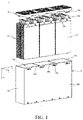
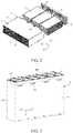
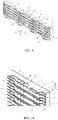
FIG. 1 andFIG. 2 are structural schematic diagrams of a battery pack according to an embodiment of the present application; -
FIG. 3 is a schematic diagram of a cell module and a housing after assembly according to the embodiment of the present application; -
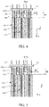
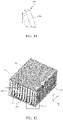
FIG. 4 is a cross-sectional schematic diagram of a first structural member and a second structural member assembled with the cell module according to the embodiment of the present application; -
FIG. 5 is another cross-sectional schematic diagram of the first structural member and the second structural member assembled with the cell module according to the embodiment of the present application; -
FIG. 6 is a structural schematic diagram of a cell according to the embodiment of the present application; -
FIG. 7 is a schematic diagram of positions of two adjacent cells in the present application; -
FIG. 8 is a schematic diagram of positions of a plurality of cells in the cell module of the present application; -
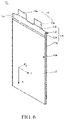
FIG. 9 is a structural schematic diagram of a first wall according to the embodiment of the present application; -
FIG. 10 is an enlarged schematic view of a region shown by dashed lines inFIG. 9 ; -
FIG. 11 is a structural schematic diagram of a protrusion shown inFIG. 9 ; -
FIG. 12 is a partial structural schematic diagram of the battery pack according to another embodiment of the present application; -
FIG. 13 is an enlarged schematic view of a region I indicated by dashed lines inFIG. 12 ; -
FIG. 14 is an enlarged schematic view of a region II indicated by dashed lines inFIG. 12 . - In order to make the object, technical solution and advantages of the present application clearer, the technical solution of the present application will be clearly described in conjunction with the embodiments and the accompanying drawings. It is obvious that the described embodiments are only a part of the embodiments, without covering all embodiments. Based on the embodiments in the present application, the following embodiments and their technical features may be combined with each other without conflict.
- In particular scenarios, the battery pack includes but is not limited to all kinds of primary batteries, secondary batteries, fuel batteries, solar batteries and capacitor (e.g., super capacitor) batteries. The battery pack may preferably be a lithium secondary battery including but not limited to a lithium metal secondary battery, a lithium ion secondary battery, a lithium polymer secondary battery and a lithium ion polymer secondary battery. Any cell in the battery pack includes, but is not limited to, soft pack cells.
- Referring to
FIGS. 1 to 9 , abattery pack 1 includes acell module 10 and a firststructural member 121. Thecell module 10 includes a plurality ofcells 11 stacked in the first direction x. Thecell 11 includes an electrode assembly (not shown), acell case 12, and atab 13. Thetab 13 is connected to the electrode assembly and is led out from thecell case 12. The firststructural member 121 is made of an insulating material. Optionally, the firststructural member 121 is made of an insulating material such as plastic. Optionally, an outer surface of the firststructural member 121 is made of an insulating material. - The
cell case 12 includes anaccommodation portion 12a for accommodating an electrode assembly (not shown), and a sealing part 12b extending outward from a periphery of theaccommodation portion 12a. The sealing part 12b includes afirst sealing part 12c, a second sealing part 12d and athird sealing part 12e. Thetab 13 extends out of thecell case 12 from thefirst sealing part 12c. The second sealing part 12d is arranged on opposite sides of theaccommodation portion 12a in a second direction y. Thethird sealing part 12e extends from the second sealing part 12d and connects thefirst sealing part 12c and the second sealing part 12d. The second direction y is perpendicular to the first direction x. - Referring further to
FIGS. 1 to 8 , the plurality ofcells 11 may be arranged in such a manner that twoadjacent cells 11 are grouped together, and the twocells 11 include afirst cell 111 and asecond cell 112. Thethird sealing part 12e of thefirst cell 111 is provided on a side of thefirst sealing part 12c of thefirst cell 11 close to thesecond cell 112, and thethird sealing part 12e of thesecond cell 112 is provided on a side of thefirst sealing part 12c of thesecond cell 112 close to thefirst cell 111. Thethird sealing part 12e of thefirst cell 111 is disposed oriented toward thethird sealing part 12e of thesecond cell 112, and thethird sealing part 12e of thesecond cell 112 is disposed oriented toward thethird sealing part 12e of thefirst cell 111. - In each group, the first
structural member 121 is disposed between thethird sealing part 12e of thefirst cell 111 and thethird sealing part 12e of thesecond cell 112 in the first direction x. Thecell case 12 includes an aluminum-plastic film, and the firststructural member 121 can be used to separate the aluminum-plastic films of thefirst cell 111 and thesecond cell 112, thereby limiting the electronic circulation loop between the aluminum-plastic film of one of thefirst cell 111 and thesecond cell 112 and the negative electrode of the other, improving electrochemical corrosion, and being beneficial to improving the safety performance of thecell 11 and thebattery pack 1. - In the
cell module 10, a plurality ofcells 11 may be connected in series or in parallel, to form an effective power supply and/or charging unit of thebattery pack 1. The number ofcells 11 can be determined according to the power demand. Optionally, as shown inFIGS. 1 to 3 , thetabs 13 of the plurality ofcells 11 may be provided on the same side of thebattery pack 1, where thetabs 12 of thefirst cell 111 and thesecond cell 112 are also provided on the same side of thebattery pack 1. - The
cell 11 may also include an electrolyte or the like provided in theaccommodation portion 12a. In the case where thecell 11 includes positive and negative polarities, the electrode assembly includes a positive plate and a negative plate, and an insulating film disposed there between. The electrode assembly can be formed by winding or stacking a plurality of plates. One end of thetab 13 extends into thecell case 12 and is electrically connected with the plates of corresponding polarity. The other end of thetab 13 extends out from thecell case 12. Thetab 13 includes afirst tab 13a which is a negative tab and asecond tab 13b which is a positive tab. Thefirst tab 13a is electrically connected with the negative plate and extends from inside to outside of thecell case 12, and thesecond tab 13b is electrically connected with the positive plate and extends from inside to outside of thecell case 12. In other embodiments, thefirst tab 13a may be a positive tab and thesecond tab 13b may be a negative tab. The configuration of thetab 13 of the present application is described in some instances herein by taking one of them as an example. - The
cell case 12 may be used to form a shape of thecell 11 and may also be used to define an external appearance of thecell 11. Internal elements such as the electrode assembly and electrolyte are accommodated in theaccommodating portion 12a, and these internal elements are protected by thecell case 12, thereby improving the protection effect and safety of thecell 11. - The sealing part 12b can be used for sealing and restricting leakage of electrolyte from an end portion and entry of impurities such as water and oxygen outside the
cell case 12 into theaccommodating portion 12a. Thefirst sealing part 12c may be used to seal a joint of thecell case 12 and thetab 13. - Referring to
FIGS. 1 to 5 , thebattery pack 1 further includes ahousing 30 housing a plurality ofcells 11, and thecell module 10 is generally rectangular as a whole. Optionally, thehousing 30 includes afirst wall 31, a second wall 32 and four side walls, and the four side walls include afirst side wall 331, asecond side wall 332, athird side wall 333 and afourth side wall 334. Thefirst wall 31 is disposed adjacent to thetab 13 of thecell 11, and thefirst wall 31 and the second wall 32 are disposed opposite to each other in a third direction z. The four side walls are connected between thefirst wall 121 and thesecond wall 122, thefirst side wall 331 and thesecond side wall 332 are disposed opposite to each other in the second direction y, thethird side wall 333 and thefourth side wall 334 are disposed opposite to each other in the first direction x, the second direction y is perpendicular to a plane where the first direction x and the third direction z lie, and the first direction x may be perpendicular to the third direction z. - In some scenarios, the second wall 32 and the four side walls may be an integrally formed structural member, and the
first wall 31 is detachably connected to the side walls to receive and protect thecell module 10. For example, as shown inFIGS. 1 to 3 , thethird side wall 333 and thefourth side wall 334 are provided with protrusions 33a, thefirst wall 31 is provided withsockets 31a on both side edges in the first direction x, and the protrusions 33a are inserted into the correspondingsockets 31a, so that thefirst wall 331 can be mounted and fixed to the side walls to form a receivingcavity 30a. The number of thesockets 31a and the protrusions 33a may be plural, which facilitates enhancing the stability of the structural connection. It should be understood that the number ofsockets 31a and protrusions 33a shown inFIGS. 1 to 3 are shown by example only. - A plurality of
cells 11 may be disposed in thehousing 30 in a predetermined manner, for example, the plurality ofcells 11 are divided into a plurality of columns, each column ofcells 11 including a plurality of groups, each group including afirst cell 111 and asecond cell 112. Thehousing 30 is provided with aseparator 30b, and two adjacent columns ofcells 11 are separated by theseparator 30b. Optionally, theseparator 30b includes an insulating member including an insulating material, and theseparator 30b can be used to separate the aluminum-plastic films of two adjacent columns ofcells 11 to improve electrochemical corrosion. - The first
structural member 121 is provided on thefirst wall 31 and extends to a position between thethird sealing part 12e of thefirst cell 111 and thethird sealing part 12e of the adjacentsecond cell 112 in the third direction z. In some scenarios, for example, as shown inFIGS. 4, 5 ,8 to 10 , the firststructural member 121 includes afirst part 121a and asecond part 121b. In the first direction x, thefirst part 121a is disposed between athird sealing part 12e of thefirst cell 111 and thethird sealing part 12e of the adjacentsecond cell 112. Thesecond part 121b is disposed between thefirst sealing part 12c of thefirst cell 111 and thefirst sealing part 12c of the adjacentsecond cell 112. Optionally, the firststructural member 121 includes twofirst parts 121a with thesecond part 121b disposed there between. Optionally, thefirst part 121a and thesecond part 121b are insulating members of a plate-like structure, which facilitates the entry of the firststructural member 121 into a position between thefirst cell 111 and thesecond cell 112 in a scenario where thefirst wall 31 is assembled with the side walls. - In some embodiments, in the first direction x, an orthographic projection of the
third sealing part 12e is at least partially located in an orthographic projection of thefirst part 121a, which is beneficial for thefirst part 121a to isolate thethird sealing part 12e of thefirst cell 111 from thethird sealing part 12e of the adjacentsecond cell 112, thereby improving the isolation effect and improving electrochemical corrosion. - As shown in
FIGS. 4 and 5 , in the third direction z, a length of a portion that is of thefirst part 121a and disposed between thethird sealing parts 12e is H1, and a length of a portion that is of thesecond part 121b and disposed between thefirst sealing parts 12c is H2, where H1 is less than H2. - In a scenario where the
first wall 31 is assembled with the side walls in the third direction z, thesecond part 121b is first extended to a position between thefirst sealing part 12c of thefirst cell 111 and thefirst sealing part 12c of the adjacentsecond cell 112 to implement preliminary positioning, which is beneficial for thefirst part 121a to enter a position between thethird sealing part 12e of thefirst cell 111 and thethird sealing part 12e of the adjacentsecond cell 112. Optionally, in the first direction x, an orthographic projection of a portion that is of thefirst part 121a and disposed between thethird sealing parts 12e is located in the orthographic projection of thefirst sealing part 12c. - In the third direction z, a length of the
third sealing part 12e is H0 which may be a length of thethird sealing part 12e protruding from an end face of theaccommodating portion 12a. Optionally, H1 ≥ 5% of∗H0. In the scenario where thefirst wall 31 is assembled with the side walls in the third direction z, thefirst part 121a extends from a free end of the third sealing part12e, and a length of thefirst part 121a extending between thethird sealing parts 12e is greater than or equal to 5% of a height of thethird sealing part 12e, which can reduce the contact between the adjacentthird sealing parts 12e during manufacture or transportation. - Referring to
FIGS. 8 ,9 and 10 , in one embodiment, the firststructural member 121 further includes a third part 121c disposed between thefirst part 121a and thesecond part 121b. An inclined surface 121d is provided on a side of the third part 121c oriented toward thecell 11, and the inclined surface 121d is at an acute angle to the second direction y. In a scenario where thefirst wall 31 is assembled with the side walls in the third direction z, the inclined surface 121d is beneficial for thefirst part 121a to be guided into a position between thethird sealing part 12e of thefirst cell 111 and thethird sealing part 12e of the adjacentsecond cell 112. - Referring further to
FIGS. 1-5 , the plurality ofcells 11 further include athird cell 113 disposed adjacent to thesecond cell 112 for two groups adjacent in the first direction x. Thethird sealing part 12e of thethird cell 113 is disposed opposite to thethird sealing part 12e of thesecond cell 112, and it should be understood that thethird cell 113 may also act as thefirst cell 111 or thesecond cell 112 in a single group. - The
first wall 31 may also be provided with a secondstructural member 122 including an insulating material. In the first direction x, the secondstructural member 122 is disposed between the sealing part joint 12f of thesecond cell 112 and the sealing part joint 12f of the adjacentthird cell 113. The sealing part joint 12f is a joint between thefirst sealing part 12c and thethird sealing part 12e. The secondstructural member 122 can separate the aluminum-plastic films of thecell case 12 in thesecond cell 112 and thethird cell 113, which is beneficial to improve the electrochemical corrosion. Optionally, the secondstructural member 122 is made of an insulating material such as plastic. Optionally, an outer surface of the secondstructural member 122 is made of an insulating material. - In some scenarios, as shown in
FIGS. 4, 5 , and8-10 , the secondstructural member 122 includes afourth part 122a and afifth part 122b, in the first direction x, thefourth part 122a is disposed between a sealing part joint 12f of thesecond cell 112 and a sealing part joint 12f of the adjacentthird cell 113, and thefifth portion 122b is disposed between thefirst sealing part 12c of thesecond cell 112 and thefirst sealing part 12c of the adjacentthird cell 113. Optionally, both thefourth part 122a and thefifth part 122b may be plate-shaped insulating structural members, facilitating the entry of the secondstructural member 122 into a position between thesecond cell 112 and thethird cell 113 in the scenario of assembling thefirst wall 31 and the side walls. - In one embodiment, the orthographic projection of the sealing part joint 12f is at least partially located in the orthographic projection of the
fourth part 122a, which is beneficial for thefourth part 122a to isolate the sealing part joint 12f of thesecond cell 112 from the sealing part joint 12f of thethird cell 113, thereby improving the isolation effect and improving the electrochemical corrosion. - In the third direction z, a length of a portion that is of the
fourth part 122a and disposed between the sealingparts 12f is H21, and a length of a portion that is of thefifth portion 122b and disposed between thefirst sealing parts 12c is H22, where H21 is less than H22. In the scenario where thefirst wall 31 is assembled with the side walls in the third direction z, thefifth portion 122b first extends between thefirst sealing part 12c of thesecond cell 112 and thefirst sealing part 12c of the adjacentthird cell 113 to implement preliminary positioning, which is beneficial for thefourth part 122a to enter a position between the sealing part joint 12f of thesecond cell 112 and the sealingpart joint 12f the adjacentthird cell 113. - Referring to
FIGS. 8 ,9 and 10 , in one embodiment, the secondstructural member 122 further includes a sixth portion 122c disposed between thefourth part 122a and thefifth portion 122b. An inclined surface 122d is provided on a side of the sixth portion 122c oriented toward thecell 11, and the inclined surface 122d is at an acute angle to the second direction y. In a scenario where thefirst wall 31 is assembled with the side walls in the third direction z, the inclined surface 122d is beneficial for thefourth part 122a to be guided into a position between the sealing part joint 12f of thesecond cell 112 and the sealing part joint 12f of the adjacentthird cell 113. - In one embodiment, the first
structural member 121 and the secondstructural member 122 are essentially the same. - Referring to
FIGS. 1-10 , thefirst wall 31 may include a plurality ofside plates 311 forming a receiving space, for example, fourside plates 311 are connected end to end to form a receiving space. The firststructural member 121 and the secondstructural member 122 are arranged in the receiving space. Twofirst parts 121a of the firststructural member 121 are respectively connected to the twoside plates 311 disposed opposite to each other in the second direction y, which is beneficial for isolation of thethird sealing part 12e of thefirst cell 111 from thethird sealing part 12e of the adjacentsecond cell 112. Twofourth parts 122a of the secondstructural member 122 are respectively connected to the twoside plates 311 disposed opposite to each other in the second direction y, which is beneficial for isolation of the sealing part joint 12f of thethird cell 112 from the sealing part joint 12f of the adjacentthird cell 113. - In the
first wall 31, the firststructural member 121, the secondstructural member 122 and other portions of thefirst wall 31 may be integrally molded insulating plates, such as by a low pressure injection molding process. In the first direction x, the firststructural member 121 and the secondstructural member 122 are arranged at intervals in turn, and a throughhole 124 is arranged between the adjacent firststructural member 121 and secondstructural member 122, through which thetab 13 of thecell 11 passes and extends to the outside of thehousing 30. The throughhole 124 may facilitate rapid heat dissipation of thecell 11. - Referring further to
FIGS. 8 ,9 ,10 and11 , the first and secondstructural members convex portions 123, a side surface of theconvex portion 123 oriented toward the sealing part 12b including aninclined surface 123a, and an angle α between theinclined surface 123a and the third direction z is an acute angle in the third direction z. In one embodiment, theconvex portion 123 is provided in thesecond part 121, and in the third direction z, a length of theconvex portion 123 does not exceed the length H2 of the portion that is of thesecond part 121b and disposed between thefirst sealing parts 12c, so as to guide thetab 13 during the assembly process and facilitate passage of thetab 13 through the throughhole 124. - It should be understood that in other embodiments, one of the first
structural member 121 and the secondstructural member 122 may be provided with theconvex portion 123, and the other may not be provided with theconvex portion 123. - Optionally, in the third direction z, a thickness of either of the first
structural member 121 and the secondstructural member 122 may decrease, for example, a thickness of thesecond part 121b of the firststructural member 121 decreases, and a thickness of thefifth portion 122b of the secondstructural member 122 decreases. - Structural elements of the same name are identified by the same reference signs in the embodiments of the present application. On the basis of, but mainly different from, the foregoing description of the embodiment, referring to
FIGS. 12 to 14 , thefirst side wall 331 and thesecond side wall 332 are respectively provided with the firststructural member 121, and thefirst side wall 331 and thesecond side wall 332 are disposed opposite to each other in the second direction y. In the first direction x, the firststructural member 121 is disposed between thethird sealing part 12e of thefirst cell 111 and thethird sealing part 12e of the adjacentsecond cell 112. Optionally, the firststructural member 121, thefirst side wall 331 and thesecond side wall 332 are integrally molded by an injection molding process. - The first
structural member 121 may include an insulating plate and extend in the second direction y between thethird sealing part 12e of thefirst cell 111 and thethird sealing part 12e of the adjacentsecond cell 112. - Optionally, in the third direction z, a width of the first
structural member 121 is gradually reduced, which is beneficial for the firststructural member 121 to be guided into a position between thethird sealing part 12e of thefirst cell 111 and thethird sealing part 12e of the adjacentsecond cell 112. - In this embodiment, in the third direction z, a length of the first
structural member 121 extending to a position between thethird sealing part 12e of thefirst cell 111 and thethird sealing part 12e of the adjacentsecond cell 112 is H1. The height H1 of the firststructural member 121 can still satisfy that H1≥5%∗H0. - As shown in
FIGS. 12 to 14 , a plurality ofcells 11 are arranged in thehousing 30 in a column, and the plurality ofcells 11 include a plurality of groups, each group include afirst cell 111 and asecond cell 112. The secondstructural member 122 may be an original side plate of thehousing 30, and is disposed between two adjacent groups. - Another embodiment of the present application provides an electrical device, which includes a load and a
battery pack 1 of any of the above embodiments, and thebattery pack 1 supplies power to the load. - The electrical device can be implemented in various specific forms. For example, in practical application scenarios, the electrical device includes but is not limited to: standby power supply, unmanned aerial vehicle, single-wheeled, two-wheeled or more electric vehicles, motorcycles, bicycles, lighting appliances, toys, electric tools, industrial and commercial energy storage or household energy storage systems, etc.
- Since the electrical device has the
battery pack 1 of any of the foregoing embodiments, the electrical device can produce the beneficial effects that thebattery pack 1 of the corresponding embodiment has. - The above embodiments are only part of the embodiments of the present application, and are not intended to limit the patent scope of the present application. Any equivalent structural transformation made by using the description and accompanying drawings is included in the scope of patent protection of the present application.
- In the absence of more restrictions, an element defined by the sentence "including a..." does not exclude the existence of other identical elements in the process, method, article or device including this element. In addition, components, features, and elements having the same name in different embodiments may have the same meaning or may have different meanings, and their specific meanings need to be determined by their interpretation in this specific embodiment or further in conjunction with the context in this specific embodiment.
- In addition, in the description of embodiments of the present application, orientation or positional relationships indicated by terms such as "center", "longitudinal", "transverse", "length", "width", "thickness", "up", "down", "front", "back", "left", "right", "vertical", "horizontal", "top", "bottom", "inner", "outer", "clockwise", "counterclockwise", etc. are based on the orientation or positional relationships shown in the drawings, for ease of description of the technical solutions of the corresponding embodiments of the present application and simplification of the description only, these terms do not indicate or imply that the device or element referred to must have a specific orientation or be constructed and operated in a specific orientation, and therefore cannot be construed as limitations to the present application.
- Although the terms "first, second, third" and the like are used herein to describe various kinds of information, such information should not be limited to these terms. These terms are only used to distinguish the same type of information from each other. As used herein, the singular forms "a", "a" and "the" are intended to include the plural forms as well. The terms "or" and "and/or" are construed as inclusive or mean any one or any combination. Exceptions to this definition occur only when combinations of elements, functions, steps, or operations are inherently mutually exclusive in some way.
Claims (15)
- A battery pack (1), comprising: a plurality of cells (11) stacked in a first direction (x); wherein each cell (11) comprises an electrode assembly, a cell case (12), and a tab (13); the cell case (12) comprises an accommodation portion (12a) configured to accommodate the electrode assembly and a sealing part (12b) extending outward from a periphery of the accommodation portion (12a); the tab (13) is connected to the electrode assembly and extends out from the cell case (12), the sealing parts (12b) comprise a first sealing part (12c), a second sealing part (12d) and a third sealing part (12e); the tab (13) extends out of the cell case (12) from the first sealing part (12c); and, in a second direction (y), the second sealing part (12d) is disposed on two opposite sides of the accommodation portion (12a), and the third sealing part (12e) extends from the second sealing part (12d) and connects the first sealing part (12c) and the second sealing part (12d);characterized in that, the plurality of cells (11) comprise a first cell (111) and a second cell (112) adjacent to each other, the third sealing part (12e) of the first cell (111) is disposed oriented towards the third sealing part (12e) of the second cell (112), and the third sealing part (12e) of the second cell (112) is disposed oriented towards the third sealing part (12e) of the first cell (111); andthe battery pack (1) further comprises a first structural member (121), the first structural member (121) comprises an insulating material, and, in the first direction (x), the first structural member (121) is disposed between the third sealing part (12e) of the first cell (111) and the third sealing part (12e) of the second cell (112).
- The battery pack (1) according to claim 1, characterized in that, the battery pack (1) further comprises a housing (30) for accommodating the plurality of cells (11); the housing (30) comprises a first wall (31), a second wall (32) and a plurality of side walls; the first wall (31) and the second wall (32) are disposed opposite to each other in a third direction (z), the first structural member (121) is disposed on the first wall (31), and the first structural member (121) extends between the third sealing part (12e) of the first cell (111) and the third sealing part (12e) of the second cell (112) in the second direction (y).
- The battery pack (1) according to claim 2, characterized in that, the first structural member (121) comprises a first part (121a) disposed between the third sealing part (12e) of the first cell (111) and the third sealing part (12e) of the second cell (112); and a second part (121b) disposed between the first sealing part (12c) of the first cell (111) and the first sealing part (12c) of the second cell (112) in the first direction (x).
- The battery pack (1) according to claim 3, characterized in that, an orthographic projection of the third sealing part (12e) is at least partially located in an orthographic projection of the first part (121a) in the first direction (x).
- The battery pack (1) according to claim 3, characterized in that, in a third direction (z), a length of a portion of the first part (121a) disposed between the third sealing part (12e) is H1, and a length of a portion of the second part (121b) disposed between the first sealing part (12c) is H2, where H1 is less than H2.
- The battery pack (1) according to claim 5, characterized in that, a length of the third sealing part (12e) is H0,and H1 ≥ 5% of ∗H0.
- The battery pack (1) according to claim 5, characterized in that, the first structural member (121) further comprises a third part (121c) connecting the first part (121a) and the second part (121b), and a side of the third part (121c) oriented toward the cell (11) is provided with an inclined surface (121d), and the inclined surface (121d) is at an acute angle to the second direction (y).
- The battery pack (1) according to claim 2, characterized in that, the first wall (31) comprises a plurality of side plates (311) forming a receiving space, the first structural member (121) is disposed in the receiving space, and the first part (121a) is connected with the side plates (311).
- The battery pack according to any one of claims 2 to 8, characterized in that, the plurality of cells (11) further comprise a third cell (113) disposed adjacent to the second cell (112), and the third sealing part (12e) of the third cell (113) is disposed opposite to the third sealing part (12e) of the second cell (112); and
the battery pack (1) further comprises a second structural member (122) disposed on the first wall (31); in the first direction (x), the second structural member (122) is disposed between a sealing part joint (12f) of the second cell (112) and a sealing part joint (12f) of the third cell (113), and the sealing part joint (12f) is a joint of the first sealing part (12c) and the third sealing part (12e). - The battery pack (1) according to claim 1, characterized in that, the battery pack (1) further comprises a housing (30) for accommodating the plurality of cells (11), the housing (30) comprising a first side wall (331) and a second side wall (332) disposed opposite to each other in the second direction (y), the first structural member (121) is disposed in at least one of the first side wall (331) and the second side wall (332).
- The battery pack (1) according to claim 2, characterized in that, the cell case (12) comprises an aluminum-plastic film.
- The battery pack (1) according to claim 9, characterized in that, a through hole (124) is disposed between adjacent first and second structural members (122), and the tab (13) passes through the through hole (124) and extends to an outside of the housing (30).
- The battery pack (1) according to claim 9, characterized in that, the second structural member (122) comprises a fourth part (122a) disposed between the sealing part joint (12f) of the second cell (112) and a sealing part joint (12f) of the third cell (113) in the first direction (x) and a fifth part (122b) disposed between the first sealing part (12c) of the second cell (112) and the first sealing part (12c) of the third cell (113).
- The battery pack (1) according to claim 13, characterized in that, an orthographic projection of the sealing part joint (12f) is located in an orthographic projection of the fourth part (122a) in the first direction (x).
- An electrical device comprising a load and a battery pack (1) according to any one of claims 1 to 14, wherein the battery pack (1) supplies power to the load.
Applications Claiming Priority (1)
| Application Number | Priority Date | Filing Date | Title |
|---|---|---|---|
| CN202110710787.0A CN113314812A (en) | 2021-06-25 | 2021-06-25 | Battery pack and electric equipment |
Publications (1)
| Publication Number | Publication Date |
|---|---|
| EP4113708A1 true EP4113708A1 (en) | 2023-01-04 |
Family
ID=77380225
Family Applications (1)
| Application Number | Title | Priority Date | Filing Date |
|---|---|---|---|
| EP22181075.7A Pending EP4113708A1 (en) | 2021-06-25 | 2022-06-24 | Battery pack and electrical device |
Country Status (2)
| Country | Link |
|---|---|
| EP (1) | EP4113708A1 (en) |
| CN (1) | CN113314812A (en) |
Families Citing this family (2)
| Publication number | Priority date | Publication date | Assignee | Title |
|---|---|---|---|---|
| WO2024036494A1 (en) * | 2022-08-16 | 2024-02-22 | 厦门新能达科技有限公司 | Battery pack and electric device |
| CN115207519B (en) * | 2022-09-15 | 2022-11-22 | 上海汽车集团股份有限公司 | Vehicle power battery and vehicle power battery pack |
Citations (3)
| Publication number | Priority date | Publication date | Assignee | Title |
|---|---|---|---|---|
| US20140045027A1 (en) * | 2011-03-31 | 2014-02-13 | Nec Energy Devices, Ltd. | Battery pack |
| US20180331336A1 (en) * | 2016-08-18 | 2018-11-15 | Lg Chem, Ltd. | Battery module |
| US20200176727A1 (en) * | 2016-09-26 | 2020-06-04 | Nissan Motor Co., Ltd. | Assembly including unit cell and spacer |
-
2021
- 2021-06-25 CN CN202110710787.0A patent/CN113314812A/en active Pending
-
2022
- 2022-06-24 EP EP22181075.7A patent/EP4113708A1/en active Pending
Patent Citations (3)
| Publication number | Priority date | Publication date | Assignee | Title |
|---|---|---|---|---|
| US20140045027A1 (en) * | 2011-03-31 | 2014-02-13 | Nec Energy Devices, Ltd. | Battery pack |
| US20180331336A1 (en) * | 2016-08-18 | 2018-11-15 | Lg Chem, Ltd. | Battery module |
| US20200176727A1 (en) * | 2016-09-26 | 2020-06-04 | Nissan Motor Co., Ltd. | Assembly including unit cell and spacer |
Also Published As
| Publication number | Publication date |
|---|---|
| CN113314812A (en) | 2021-08-27 |
Similar Documents
| Publication | Publication Date | Title |
|---|---|---|
| EP4113708A1 (en) | Battery pack and electrical device | |
| JP6392323B2 (en) | Battery system | |
| CN106941138B (en) | Power storage device and method for manufacturing power storage device | |
| KR101266617B1 (en) | Secondary battery and battery system | |
| US20240079713A1 (en) | Enclosure, battery and power consuming device | |
| KR20170062845A (en) | Battery Module Comprising Unit Module Having Simple Structure | |
| EP4044329A1 (en) | Battery box body, battery, electric device, and method and device for manufacturing box body | |
| US20230095565A1 (en) | Large pouch module and electric vehicle including the same | |
| US20140113177A1 (en) | Lead-acid battery design having versatile form factor | |
| JP2009224227A (en) | Battery module and battery pack with the same | |
| CN216720098U (en) | Battery cover plate, battery monomer, battery and electric equipment | |
| KR20150070701A (en) | Battery Module having Bus Bar employed with External Input-Output Terminal | |
| CN215732110U (en) | Battery pack and electric equipment | |
| US20220123414A1 (en) | Partition plate, battery module, battery pack, and device | |
| CN113258195B (en) | Battery pack, manufacturing method thereof and electric equipment | |
| US20190341590A1 (en) | Battery pack | |
| US20230178844A1 (en) | Power supply device, and vehicle and electrical storage device each equipped with same | |
| CN116325326A (en) | Battery, electric device, method and equipment for preparing battery | |
| KR20230015253A (en) | Battery, power consumption device, battery manufacturing method and device | |
| CN217114627U (en) | Battery and electric device | |
| CN218414973U (en) | Partition plate assembly, battery module, battery pack and electric device | |
| CN219801223U (en) | Electrode terminal, secondary battery, battery pack, and vehicle | |
| US20240055706A1 (en) | Battery, power consumption apparatus, and method and apparatus for producing battery | |
| CN114696022B (en) | Battery box, battery, electric equipment, and method and device for preparing box | |
| CN217485601U (en) | Battery shell, battery monomer, battery and power consumption device |
Legal Events
| Date | Code | Title | Description |
|---|---|---|---|
| PUAI | Public reference made under article 153(3) epc to a published international application that has entered the european phase |
Free format text: ORIGINAL CODE: 0009012 |
|
| STAA | Information on the status of an ep patent application or granted ep patent |
Free format text: STATUS: REQUEST FOR EXAMINATION WAS MADE |
|
| 17P | Request for examination filed |
Effective date: 20220624 |
|
| AK | Designated contracting states |
Kind code of ref document: A1 Designated state(s): AL AT BE BG CH CY CZ DE DK EE ES FI FR GB GR HR HU IE IS IT LI LT LU LV MC MK MT NL NO PL PT RO RS SE SI SK SM TR |