EP4113703A1 - Battery and electrical device - Google Patents
Battery and electrical device Download PDFInfo
- Publication number
- EP4113703A1 EP4113703A1 EP22772773.2A EP22772773A EP4113703A1 EP 4113703 A1 EP4113703 A1 EP 4113703A1 EP 22772773 A EP22772773 A EP 22772773A EP 4113703 A1 EP4113703 A1 EP 4113703A1
- Authority
- EP
- European Patent Office
- Prior art keywords
- flow channel
- battery
- heat exchange
- exchange plate
- inlet
- Prior art date
- Legal status (The legal status is an assumption and is not a legal conclusion. Google has not performed a legal analysis and makes no representation as to the accuracy of the status listed.)
- Pending
Links
Images




Classifications
-
- H—ELECTRICITY
- H01—ELECTRIC ELEMENTS
- H01M—PROCESSES OR MEANS, e.g. BATTERIES, FOR THE DIRECT CONVERSION OF CHEMICAL ENERGY INTO ELECTRICAL ENERGY
- H01M10/00—Secondary cells; Manufacture thereof
- H01M10/60—Heating or cooling; Temperature control
- H01M10/61—Types of temperature control
- H01M10/617—Types of temperature control for achieving uniformity or desired distribution of temperature
-
- H—ELECTRICITY
- H01—ELECTRIC ELEMENTS
- H01M—PROCESSES OR MEANS, e.g. BATTERIES, FOR THE DIRECT CONVERSION OF CHEMICAL ENERGY INTO ELECTRICAL ENERGY
- H01M10/00—Secondary cells; Manufacture thereof
- H01M10/42—Methods or arrangements for servicing or maintenance of secondary cells or secondary half-cells
- H01M10/48—Accumulators combined with arrangements for measuring, testing or indicating the condition of cells, e.g. the level or density of the electrolyte
- H01M10/482—Accumulators combined with arrangements for measuring, testing or indicating the condition of cells, e.g. the level or density of the electrolyte for several batteries or cells simultaneously or sequentially
-
- H—ELECTRICITY
- H01—ELECTRIC ELEMENTS
- H01M—PROCESSES OR MEANS, e.g. BATTERIES, FOR THE DIRECT CONVERSION OF CHEMICAL ENERGY INTO ELECTRICAL ENERGY
- H01M10/00—Secondary cells; Manufacture thereof
- H01M10/42—Methods or arrangements for servicing or maintenance of secondary cells or secondary half-cells
- H01M10/48—Accumulators combined with arrangements for measuring, testing or indicating the condition of cells, e.g. the level or density of the electrolyte
- H01M10/486—Accumulators combined with arrangements for measuring, testing or indicating the condition of cells, e.g. the level or density of the electrolyte for measuring temperature
-
- H—ELECTRICITY
- H01—ELECTRIC ELEMENTS
- H01M—PROCESSES OR MEANS, e.g. BATTERIES, FOR THE DIRECT CONVERSION OF CHEMICAL ENERGY INTO ELECTRICAL ENERGY
- H01M10/00—Secondary cells; Manufacture thereof
- H01M10/60—Heating or cooling; Temperature control
- H01M10/61—Types of temperature control
- H01M10/613—Cooling or keeping cold
-
- H—ELECTRICITY
- H01—ELECTRIC ELEMENTS
- H01M—PROCESSES OR MEANS, e.g. BATTERIES, FOR THE DIRECT CONVERSION OF CHEMICAL ENERGY INTO ELECTRICAL ENERGY
- H01M10/00—Secondary cells; Manufacture thereof
- H01M10/60—Heating or cooling; Temperature control
- H01M10/61—Types of temperature control
- H01M10/615—Heating or keeping warm
-
- H—ELECTRICITY
- H01—ELECTRIC ELEMENTS
- H01M—PROCESSES OR MEANS, e.g. BATTERIES, FOR THE DIRECT CONVERSION OF CHEMICAL ENERGY INTO ELECTRICAL ENERGY
- H01M10/00—Secondary cells; Manufacture thereof
- H01M10/60—Heating or cooling; Temperature control
- H01M10/63—Control systems
-
- H—ELECTRICITY
- H01—ELECTRIC ELEMENTS
- H01M—PROCESSES OR MEANS, e.g. BATTERIES, FOR THE DIRECT CONVERSION OF CHEMICAL ENERGY INTO ELECTRICAL ENERGY
- H01M10/00—Secondary cells; Manufacture thereof
- H01M10/60—Heating or cooling; Temperature control
- H01M10/65—Means for temperature control structurally associated with the cells
- H01M10/655—Solid structures for heat exchange or heat conduction
- H01M10/6554—Rods or plates
-
- H—ELECTRICITY
- H01—ELECTRIC ELEMENTS
- H01M—PROCESSES OR MEANS, e.g. BATTERIES, FOR THE DIRECT CONVERSION OF CHEMICAL ENERGY INTO ELECTRICAL ENERGY
- H01M10/00—Secondary cells; Manufacture thereof
- H01M10/60—Heating or cooling; Temperature control
- H01M10/65—Means for temperature control structurally associated with the cells
- H01M10/655—Solid structures for heat exchange or heat conduction
- H01M10/6556—Solid parts with flow channel passages or pipes for heat exchange
-
- H—ELECTRICITY
- H01—ELECTRIC ELEMENTS
- H01M—PROCESSES OR MEANS, e.g. BATTERIES, FOR THE DIRECT CONVERSION OF CHEMICAL ENERGY INTO ELECTRICAL ENERGY
- H01M10/00—Secondary cells; Manufacture thereof
- H01M10/60—Heating or cooling; Temperature control
- H01M10/65—Means for temperature control structurally associated with the cells
- H01M10/656—Means for temperature control structurally associated with the cells characterised by the type of heat-exchange fluid
- H01M10/6567—Liquids
-
- H—ELECTRICITY
- H01—ELECTRIC ELEMENTS
- H01M—PROCESSES OR MEANS, e.g. BATTERIES, FOR THE DIRECT CONVERSION OF CHEMICAL ENERGY INTO ELECTRICAL ENERGY
- H01M10/00—Secondary cells; Manufacture thereof
- H01M10/60—Heating or cooling; Temperature control
- H01M10/65—Means for temperature control structurally associated with the cells
- H01M10/656—Means for temperature control structurally associated with the cells characterised by the type of heat-exchange fluid
- H01M10/6567—Liquids
- H01M10/6568—Liquids characterised by flow circuits, e.g. loops, located externally to the cells or cell casings
-
- H—ELECTRICITY
- H01—ELECTRIC ELEMENTS
- H01M—PROCESSES OR MEANS, e.g. BATTERIES, FOR THE DIRECT CONVERSION OF CHEMICAL ENERGY INTO ELECTRICAL ENERGY
- H01M10/00—Secondary cells; Manufacture thereof
- H01M10/60—Heating or cooling; Temperature control
- H01M10/65—Means for temperature control structurally associated with the cells
- H01M10/653—Means for temperature control structurally associated with the cells characterised by electrically insulating or thermally conductive materials
-
- H—ELECTRICITY
- H01—ELECTRIC ELEMENTS
- H01M—PROCESSES OR MEANS, e.g. BATTERIES, FOR THE DIRECT CONVERSION OF CHEMICAL ENERGY INTO ELECTRICAL ENERGY
- H01M50/00—Constructional details or processes of manufacture of the non-active parts of electrochemical cells other than fuel cells, e.g. hybrid cells
- H01M50/20—Mountings; Secondary casings or frames; Racks, modules or packs; Suspension devices; Shock absorbers; Transport or carrying devices; Holders
- H01M50/204—Racks, modules or packs for multiple batteries or multiple cells
-
- Y—GENERAL TAGGING OF NEW TECHNOLOGICAL DEVELOPMENTS; GENERAL TAGGING OF CROSS-SECTIONAL TECHNOLOGIES SPANNING OVER SEVERAL SECTIONS OF THE IPC; TECHNICAL SUBJECTS COVERED BY FORMER USPC CROSS-REFERENCE ART COLLECTIONS [XRACs] AND DIGESTS
- Y02—TECHNOLOGIES OR APPLICATIONS FOR MITIGATION OR ADAPTATION AGAINST CLIMATE CHANGE
- Y02E—REDUCTION OF GREENHOUSE GAS [GHG] EMISSIONS, RELATED TO ENERGY GENERATION, TRANSMISSION OR DISTRIBUTION
- Y02E60/00—Enabling technologies; Technologies with a potential or indirect contribution to GHG emissions mitigation
- Y02E60/10—Energy storage using batteries
Definitions
- This application relates to the field of battery power technologies, and in particular, to a battery and an electric device.
- a thermal management assembly is usually provided to cool down or heat up the battery. This is to ensure that the battery operates within a predetermined temperature range, avoiding excessively high or excessively low battery temperatures.
- embodiments of the present invention provide a battery and an electric device, which can separately manage temperature of battery cells in different areas.
- a battery including a first battery module, a second battery module, and a thermal management component.
- the first battery module includes a plurality of first battery cells
- the second battery module includes a plurality of second battery cells
- the plurality of second battery cells are located at the peripheries of the first battery cells.
- the thermal management component includes a first flow channel and a second flow channel, the first flow channel being configured to accommodate fluid to adjust temperature of the plurality of first battery cells, and the second flow channel being configured to accommodate fluid to adjust temperature of the plurality of second battery cells.
- the thermal management component further includes a first inlet and a second inlet, the first inlet being configured for inputting fluid into the first flow channel and the second inlet being configured for inputting fluid into the second flow channel, with the first inlet and the second inlet isolated from each other.
- the thermal management component further includes a first outlet and a second outlet, the first outlet being configured for outputting fluid in the first flow channel and the second outlet being configured for outputting fluid in the second flow channel, where the first outlet and the second outlet communicate with each other.
- the first flow channel and the second flow channel are isolated from each other.
- the battery further includes a first inlet pipeline and a second inlet pipeline, where the first inlet pipeline is configured to be connected to the first inlet to input fluid into the first flow channel; and the second inlet pipeline is configured to be connected to the second inlet to input fluid into the second flow channel.
- the battery further includes a first switch and a second switch.
- the first switch is disposed on the first inlet pipeline and configured to control connection and disconnection between the first inlet pipeline and the first flow channel.
- the second switch is disposed on the second inlet pipeline and configured to control connection and disconnection between the second inlet pipeline and the second flow channel.
- the battery further includes a first temperature sensor, a second temperature sensor, and a controller.
- the first temperature sensor is configured to sense temperature of at least one of the first battery cells
- the second temperature sensor is configured to sense temperature of at least one of the second battery cells.
- the controller is configured to be electrically connected to the first temperature sensor, the second temperature sensor, the first switch, and the second switch, and the controller is configured to control on-off of the first switch and the second switch based on temperatures sensed by the first temperature sensor and the second temperature sensor respectively.
- the thermal management component includes a heat exchange plate, the heat exchange plate being configured to perform heat exchange with the first battery module and the second battery module, and the heat exchange plate being provided with the first flow channel and the second flow channel inside.
- the heat exchange plate includes an upper heat exchange plate and a lower heat exchange plate, where the upper heat exchange plate is configured to perform heat exchange with the first battery module and the second battery module; and the lower heat exchange plate is disposed on a side of the upper heat exchange plate away from the first battery module and the second battery module.
- the first flow channel and the second flow channel are formed between the upper heat exchange plate and the lower heat exchange plate, so that fluid flows therein.
- the heat exchange plate is connected to the first battery module via a thermally conductive structural adhesive; and/or the heat exchange plate is connected to the second battery module via a thermally conductive structural adhesive.
- the first flow channel is disposed in a bent shape; and/or the second flow channel is disposed in a U shape.
- an electric device including the battery according to any one of the foregoing embodiments, the battery being configured to supply electric energy.
- the battery provided in the embodiments of the present invention includes a plurality of first battery cells and a plurality of second battery cells disposed at the peripheries of the first battery cells.
- the thermal management component includes a first flow channel, a second flow channel, a first inlet through which fluid is input into the first flow channel, and a second inlet through which fluid is input into the second flow channel.
- the first flow channel and the second flow channel can be formed as two separate flow channels for flowing, so that the first flow channel adjusts temperature of the plurality of first battery cells and the second flow channel adjusts temperature of the plurality of second battery cells, implementing temperature control of the battery cells in different areas, thereby avoiding excessive temperature differences between the battery cells and improving energy utilization of a thermal management system.
- the inventors of the present invention have found that: when a battery works, affected by arrangement of battery cells, battery cells close to an edge area commonly have low temperature. In addition, as heat of the battery is transferred from the center to the edge of the battery, battery cells in a middle area dissipate heat slowly due to heat accumulation. Therefore, large temperature differences are formed between the battery cells in the edge area and the battery cells in the middle area. As a result, it is necessary to perform temperature management on battery cells in different areas to guarantee performance of the battery.
- an embodiment of the present invention provides a battery 100, including a battery module 10 and a thermal management component 20.
- the battery module 10 is disposed on the thermal management component 20, and the thermal management component 20 is configured to adjust temperature of the battery module 10. Adjusting temperature herein may refer to raising or lowering the temperature.
- the battery module 10 includes a first battery module 11 and a second battery module 12.
- the first battery module 11 includes a plurality of first battery cells 110, where the plurality of first battery cells 110 are sequentially stacked and arranged.
- the second battery module 12 includes a plurality of second battery cells 120, where the plurality of second battery cells 120 are disposed at the peripheries of the first battery cells 110.
- a temperature of the first battery cells 110 is higher than that of the second battery cells 120.
- the plurality of second battery cells 120 include at least one row of battery cells located at a first lateral edge A1 of the battery module 10, at least one row of battery cells located at a second lateral edge A2 of the battery module 10, and at least one column of battery cells located at a third lateral edge A3 of the battery module 10.
- the plurality of second battery cells 120 are arranged in a U shape.
- the first lateral edge A1 and the second lateral edge A2 are two opposite edges.
- the first battery module 11 and the second battery module 12 are separated by a dotted box X1 for example description.
- the first battery module 11 includes the plurality of first battery cells 110 located inside the dotted box X1
- the second battery module 12 includes the plurality of second battery cells 120 located outside the dotted box X1.
- the plurality of second battery cells 120 may further include at least one column of battery cells located at a fourth lateral edge A4 of the battery module 10, and the plurality of second battery cells 120 are arranged in a "square" shape.
- the fourth lateral edge A4 and the third lateral edge A3 are two opposite edges.
- the first battery module 11 and the second battery module 12 are separated by a dotted box X2 for example description.
- the first battery module 11 includes the plurality of first battery cells 110 located inside the dotted box X2
- the second battery module 12 includes the plurality of second battery cells 120 located outside the dotted box X2.
- the plurality of second battery cells may include only at least one row of battery cells located at the first lateral edge of the battery module 10 and at least one row of battery cells located at the second lateral edge of the battery module 10, or battery cells in other low temperature areas, which is not limited herein.
- the thermal management component 20 includes a first flow channel 201 and a second flow channel 202.
- the first flow channel 201 is disposed in a bent shape, a position of the first flow channel 201 corresponds to a position of the first battery module 11, and the first flow channel 201 is configured to accommodate fluid to adjust temperature of the plurality of first battery cells 110.
- the second flow channel 202 is disposed in a U shape, the second flow channel 202 is disposed at the periphery of the first flow channel 201, a position of the second flow channel 202 corresponds to a position of the second battery module 12, and the second flow channel 202 is configured to accommodate fluid to adjust temperature of the plurality of second battery cells 120.
- the fluid accommodated in the first flow channel 201 and the second flow channel 202 may be water, gas, mixed liquid of water and glycol, or the like, and may circulate. It can be understood that, in some other embodiments, the shape of the second flow channel 202 may be set depending on an actual demand, for example, may be set as the "square" shape, the L shape, or the like. The shape of the second flow channel 202 needs to correspond to the shape of the second battery module 12 to meet a requirement for heat exchange of the second battery module 12. Preferably, the second flow channel 202 may cover each of the second battery cells 120 to increase heat exchange efficiency.
- the thermal management component 20 further includes a first inlet 203 and a second inlet 204 isolated from each other.
- the first inlet 203 communicate with one end of the first flow channel 201, and the first inlet 203 is configured for inputting fluid into the first flow channel 201.
- the second inlet 204 communicate with one end of the second flow channel 202, and the second inlet 204 is configured for inputting fluid into the second flow channel 202.
- the thermal management component 20 further includes a first outlet 205 and a second outlet 206.
- the first outlet 205 communicate with the other end of the first flow channel 201, and fluid may be input into the first flow channel 201 through the first inlet 203 and output from the first outlet 205.
- the second outlet 206 communicate with the other end of the second flow channel 202, and fluid may be input into the second flow channel 202 through the second inlet 204 and output from the second outlet 206.
- the thermal management component 20 includes a heat exchange plate 21, where the first flow channel 201 and the second flow channel 202 are disposed inside the heat exchange plate 21.
- the battery module 10 is disposed on the heat exchange plate 21, and the heat exchange plate 21 is configured to perform heat exchange with the first battery module 11 and the second battery module 12.
- the heat exchange plate 21 may be connected to the first battery module 11 or the second battery module 12 through a thermally conductive structural adhesive (not shown), so that the heat exchange plate 21 is connected and fixed to the battery module 10.
- the thermally conductive structural adhesive may fill a gap between the heat exchange plate 21 and the battery module 10, so as to enhance the heat exchange effect of the heat exchange plate 21.
- the heat exchange plate 21 includes an upper heat exchange plate 210 and a lower heat exchange plate 212, where one surface of the upper heat exchange plate 210 is connected to the lower heat exchange plate 212 and the other surface of the upper heat exchange plate 210 is connected to the first battery module 11 and the second battery module 12.
- the first flow channel 201 and the second flow channel 202 are formed between the upper heat exchange plate 210 and the lower heat exchange plate 212.
- Materials of the upper heat exchange plate 210 and the lower heat exchange plate 212 may be metal aluminum or other aluminum alloy, and the upper heat exchange plate 210 and the lower heat exchange plate 212 may be fastened by means of braze welding or in other welding manners.
- the surface of the lower heat exchange plate 212 facing the upper heat exchange plate 210 is provided with a first groove 201a and a second groove 202a, and the upper heat exchange plate 210 covers the lower heat exchange plate 212 to close the first groove 201a and the second groove 202a to form the first flow channel 201 and the second flow channel 202.
- first groove and the second groove may alternatively be formed in the upper heat exchange plate, the lower heat exchange plate covers the upper heat exchange plate to form the first flow channel and the second flow channel, or the upper heat exchange plate and the lower heat exchange plate each are provided with the first groove and the second groove corresponding in position, and the upper heat exchange plate and the lower heat exchange plate are spliced to form the first flow channel and the second flow channel, which is not limited herein.
- the upper heat exchange plate 210 is provided with the first inlet 203 and the second inlet 204, and the first inlet 203 and the second inlet 204 penetrate through the upper heat exchange plate 210.
- the first inlet 203 communicates the first flow channel 201 with the outside
- the second inlet 204 communicates the second flow channel 202 with the outside.
- the upper heat exchange plate 210 is further provided with the first outlet 205 and the second outlet 206, and the first outlet 205 and the second outlet 206 penetrate through the upper heat exchange plate 210.
- the first outlet 205 communicates the first flow channel 201 with the outside
- the second outlet 206 communicates the second flow channel 202 with the outside.
- the first outlet 205 and the second outlet 206 do not communicate with each other, so that the first flow channel 201 and the second flow channel 202 are isolated from each other.
- the first outlet 205 and the second outlet 206 may alternatively communicate with each other, and fluid in the first flow channel 201 and the second flow channel 202 is discharged through a main outlet.
- the second outlet 206 may be used as the main outlet, where the first outlet 205 of the first flow channel 201 communicates with the second flow channel 202, and after being input into the first flow channel 201 through the first inlet 203, fluid is input into the second flow channel 202 through the first outlet 205 and then discharged from the second outlet 206; or, the first outlet 205 may be used as the main outlet (not shown), where the second outlet 206 of the second flow channel 202 communicates with the first flow channel 201, and after being input into the second flow channel 202 through the second inlet 204, fluid is input into the first flow channel 201 through the second outlet 206 and then discharged from the first outlet 205; or, the first flow channel 201 and the second flow channel 202 both communicate with the main outlet, which is not limited
- the thermal management component 20 further includes an inlet pipeline, where the inlet pipeline is mounted on the upper heat exchange plate 210, and the inlet pipeline includes a first inlet pipeline 220 and a second inlet pipeline 222.
- An end of the first inlet pipeline 220 is connected to the first inlet 203 to input fluid into the first flow channel 201.
- the second inlet pipeline 222 is connected to the second inlet 204 to input fluid into the second flow channel 202.
- the first inlet pipeline 220 and the second inlet pipeline 222 are isolated from each other, the first inlet pipeline 220 and the second inlet pipeline 222 are connected to an external heat exchanger (not shown), and the heat exchanger is configured to perform heat exchange for fluid.
- Materials of the first inlet pipeline 220 and the second inlet pipeline 222 may be metal alloy or nylon, or the like, so as to guarantee sealing properties of the pipelines.
- the thermal management component 20 further includes a pipeline switch disposed on the inlet pipeline.
- the pipeline switch includes a first switch 230 and a second switch 232.
- the first switch 230 is disposed on the first inlet pipeline 220 and configured to control connection and disconnection between the first inlet pipeline 220 and the first flow channel 201.
- the second switch 232 is disposed on the second inlet pipeline 222 and configured to control connection and disconnection between the second inlet pipeline 222 and the second flow channel 202.
- the pipeline switch may use quick connectors disposed between the first inlet pipeline 220 and the first inlet 203 and between the second inlet pipeline 222 and the second inlet 204; or, the pipeline switch may alternatively use control valves disposed between the first inlet pipeline 220 and the heat exchanger and between the second inlet pipeline 222 and the heat exchanger.
- the first inlet pipeline 220 and the second inlet pipeline 222 are connected via a main inlet pipeline 224, the main inlet pipeline 224 is connected to an external heat exchanger, and fluid is input into the first inlet pipeline 220 and the second inlet pipeline 222 through the main inlet pipeline 224.
- the first switch 230 is disposed between the first inlet pipeline 220 and the main inlet pipeline 224, and the first switch 230 controls connection and disconnection between the first inlet pipeline 220 and the main inlet pipeline 224, so as to control connection and disconnection between the first flow channel 201 and the first inlet pipeline 220.
- the second switch 232 is disposed between the second inlet pipeline 222 and the main inlet pipeline 224, and the second switch 232 controls connection and disconnection between the second inlet pipeline 222 and the main inlet pipeline 224, so as to control connection and disconnection between the second flow channel 202 and the second inlet pipeline 222.
- the thermal management component 20 further includes a temperature sensor and a controller 25, where the controller 25 is electrically connected to the temperature sensor and the pipeline switch.
- the temperature sensor is disposed on the battery module 10 and configured to detect a temperature change of the battery module 10 and be communicatively connected to the controller 25.
- the controller 25 controls the heat exchanger to cool down fluid and opens the pipeline switch to input the fluid into the first flow channel 201 or the second flow channel 202, so that the fluid cools down the first battery module 11 or the second battery module 12; and when the temperature sensor detects that the temperature of the first battery module 11 or the second battery module 12 is lower than the preset temperature, the controller 25 controls the heat exchanger to heat up the fluid and opens the pipeline switch to input the fluid into the first flow channel 201 or the second flow channel 202, so that the fluid heats up the first battery module 11 or the second battery module 12.
- the thermal management component 20 implements automated temperature management on the battery module 10.
- the temperature sensor includes a first temperature sensor 240 and a second temperature sensor 242.
- the first temperature sensor 240 is disposed on the first battery module 11, the first temperature sensor 240 is connected to at least one of the first battery cells 110, and the first temperature sensor 240 is configured to sense temperature of the at least one of the first battery cells 110.
- the second temperature sensor 242 is disposed on the second battery module 12, the second temperature sensor 242 is connected to at least one of the second battery cells 120, and the second temperature sensor 242 is configured to sense temperature of the at least one of the second battery cells 120.
- the controller 25 is electrically connected to the first temperature sensor 240 and the first switch 230, and the controller 25 controls on-off of the first switch 230 based on a temperature sensed by the first temperature sensor 240.
- the controller 25 is also electrically connected to the second temperature sensor 242 and the second switch 232, and the controller 25 controls on-off of the second switch 232 based on a temperature sensed by the second temperature sensor 242. It can be understood that in some embodiments, there may be two controllers which are configured to control the first switch 230 and the second switch 232 respectively.
- the battery 100 further includes a housing 30, where the housing 30 is disposed outside the battery module 10 and the thermal management component 20.
- the housing 30 includes a box body 31 and a cover 32, where the cover 32 is connected to the box body 31.
- the box body 31 is provided with an accommodation space inside which both the battery module 10 and the thermal management component 20 are disposed, and the cover 32 is disposed on the box body 31 to close the accommodation space.
- the box body 31 and the cover 32 may also be made of a thermally conductive material to transfer heat of the battery module 10 or the thermal management component 20 to the outside.
- the thermal management component 20 during operation of the battery 100, heat generated by the battery module 10 is transferred to the thermal management component 20. Affected by arrangement of the battery cells, the plurality of first battery cells 110 in a middle area dissipate heat slowly due to heat accumulation, and the plurality of second battery cells 120 in an edge area commonly have a low temperature.
- the first flow channel 201 may be opened to cool down the first battery module 11 to reduce temperature differences in the battery, thereby effectively regulating the temperature differences in the battery.
- the second flow channel 202 may be opened to heat up the second battery module 12 to increase temperature of the battery cells at an outer edge of the battery, thereby guaranteeing optimum energy utilization. It can be understood that the first flow channel 201 and the second flow channel 202 may alternatively be opened simultaneously to cool down or heat up the first battery module 11 and the second battery module 12, so as to guarantee temperature uniformity of the battery module 10.
- the battery 100 is configured to supply electric energy.
- the electric device may be a device that uses battery such as a vehicle, a ship, an aircraft, an energy storage device and a low handheld electrical tool.
Landscapes
- Engineering & Computer Science (AREA)
- Chemical & Material Sciences (AREA)
- Chemical Kinetics & Catalysis (AREA)
- Electrochemistry (AREA)
- General Chemical & Material Sciences (AREA)
- Manufacturing & Machinery (AREA)
- Automation & Control Theory (AREA)
- Secondary Cells (AREA)
Abstract
Description
- This application claims priority to the
Chinese Patent Application No. 202110357856.4, filed on April 1, 2021 - This application relates to the field of battery power technologies, and in particular, to a battery and an electric device.
- With the development of new energy technologies, energy density of batteries is getting higher and higher, and the application range of batteries is becoming wider and wider. Batteries are extremely sensitive to temperature. When the temperature is excessively low or excessively high, charging and discharging capacity of the batteries is reduced and service life of the batteries is shortened. In order to control the temperature of a battery, a thermal management assembly is usually provided to cool down or heat up the battery. This is to ensure that the battery operates within a predetermined temperature range, avoiding excessively high or excessively low battery temperatures.
- In order to solve the above-mentioned technical problems, embodiments of the present invention provide a battery and an electric device, which can separately manage temperature of battery cells in different areas.
- The following technical solutions are adopted for the embodiments of the present invention to solve the technical problems.
- A battery is provided, including a first battery module, a second battery module, and a thermal management component. The first battery module includes a plurality of first battery cells, the second battery module includes a plurality of second battery cells, and the plurality of second battery cells are located at the peripheries of the first battery cells. The thermal management component includes a first flow channel and a second flow channel, the first flow channel being configured to accommodate fluid to adjust temperature of the plurality of first battery cells, and the second flow channel being configured to accommodate fluid to adjust temperature of the plurality of second battery cells. The thermal management component further includes a first inlet and a second inlet, the first inlet being configured for inputting fluid into the first flow channel and the second inlet being configured for inputting fluid into the second flow channel, with the first inlet and the second inlet isolated from each other.
- In some embodiments, the thermal management component further includes a first outlet and a second outlet, the first outlet being configured for outputting fluid in the first flow channel and the second outlet being configured for outputting fluid in the second flow channel, where the first outlet and the second outlet communicate with each other.
- In some embodiments, the first flow channel and the second flow channel are isolated from each other.
- In some embodiments, the battery further includes a first inlet pipeline and a second inlet pipeline, where the first inlet pipeline is configured to be connected to the first inlet to input fluid into the first flow channel; and the second inlet pipeline is configured to be connected to the second inlet to input fluid into the second flow channel.
- In some embodiments, the battery further includes a first switch and a second switch. The first switch is disposed on the first inlet pipeline and configured to control connection and disconnection between the first inlet pipeline and the first flow channel. The second switch is disposed on the second inlet pipeline and configured to control connection and disconnection between the second inlet pipeline and the second flow channel.
- In some embodiments, the battery further includes a first temperature sensor, a second temperature sensor, and a controller. The first temperature sensor is configured to sense temperature of at least one of the first battery cells, and the second temperature sensor is configured to sense temperature of at least one of the second battery cells. The controller is configured to be electrically connected to the first temperature sensor, the second temperature sensor, the first switch, and the second switch, and the controller is configured to control on-off of the first switch and the second switch based on temperatures sensed by the first temperature sensor and the second temperature sensor respectively.
- In some embodiments, the thermal management component includes a heat exchange plate, the heat exchange plate being configured to perform heat exchange with the first battery module and the second battery module, and the heat exchange plate being provided with the first flow channel and the second flow channel inside.
- In some embodiments, the heat exchange plate includes an upper heat exchange plate and a lower heat exchange plate, where the upper heat exchange plate is configured to perform heat exchange with the first battery module and the second battery module; and the lower heat exchange plate is disposed on a side of the upper heat exchange plate away from the first battery module and the second battery module. The first flow channel and the second flow channel are formed between the upper heat exchange plate and the lower heat exchange plate, so that fluid flows therein.
- In some embodiments, the heat exchange plate is connected to the first battery module via a thermally conductive structural adhesive; and/or the heat exchange plate is connected to the second battery module via a thermally conductive structural adhesive.
- In some embodiments, the first flow channel is disposed in a bent shape; and/or the second flow channel is disposed in a U shape.
- According to a second aspect, an electric device is provided, including the battery according to any one of the foregoing embodiments, the battery being configured to supply electric energy.
- Compared with the prior art, the battery provided in the embodiments of the present invention includes a plurality of first battery cells and a plurality of second battery cells disposed at the peripheries of the first battery cells. The thermal management component includes a first flow channel, a second flow channel, a first inlet through which fluid is input into the first flow channel, and a second inlet through which fluid is input into the second flow channel. The first flow channel and the second flow channel can be formed as two separate flow channels for flowing, so that the first flow channel adjusts temperature of the plurality of first battery cells and the second flow channel adjusts temperature of the plurality of second battery cells, implementing temperature control of the battery cells in different areas, thereby avoiding excessive temperature differences between the battery cells and improving energy utilization of a thermal management system.
- One or more embodiments are used as examples for description by using corresponding accompanying drawings. These example descriptions impose no limitation on the embodiments. Elements with a same reference sign in the accompanying drawings represent similar elements. Unless otherwise specified, the figures in the accompanying drawings impose no limitation on a scale.
-
FIG. 1 is a schematic structural diagram of a battery according to an embodiment of the present invention; -
FIG. 2 is a schematic structural diagram of a battery module of the battery shown inFIG. 1 ; -
FIG. 3 is a schematic structural diagram of a battery module of a battery according to another embodiment of the present invention; -
FIG. 4 is a schematic structural diagram of a thermal management component of the battery shown inFIG. 1 ; -
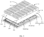
Fig. 5 is a schematic exploded view of the battery shown inFIG. 1 ; -
FIG. 6 is a schematic structural diagram of a thermal management component of a battery according to another embodiment of the present invention; -
FIG. 7 is a schematic structural diagram of a thermal management component of a battery according to another embodiment of the present invention; -
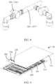
FIG. 8 is a schematic structural diagram of an inlet pipeline and a pipeline switch of the thermal management component shown inFIG. 6 ; -
FIG. 9 is a schematic structural diagram of a thermal management component of a battery according to another embodiment of the present invention; -
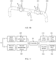
FIG. 10 is a schematic structural diagram of an inlet pipeline and a pipeline switch of the thermal management component shown inFIG. 8 ; -
FIG. 11 is a diagram of functional modules of a battery according to another embodiment of the present invention; and -
FIG. 12 is a schematic structural diagram of a battery according to another embodiment of the present invention. - The accompanying drawings are not drawn to scale.
- 100. battery
- 10. battery module
- 11. first battery module
110. first battery cell - 12. second battery module
120. second battery cell
- 11. first battery module
- 20. thermal management component
- 201. first flow channel
- 202. second flow channel
- 203. first inlet
- 204. second inlet
- 205. first outlet
- 206. second outlet
- 21. heat exchange plate
- 210. upper heat exchange plate
- 212. lower heat exchange plate
- 201a. first groove
- 202a. second groove
- 220. first inlet pipeline
- 222. second inlet pipeline
- 224. main inlet pipeline
- 230. first switch
- 232. second switch
- 240. first temperature sensor
- 242. second temperature sensor
- 25. controller
- 30. housing
- 31. box body
- 32. cover.
- For ease of understanding the present invention, the following further describes the present invention in detail with reference to the accompanying drawings and specific embodiments. It should be noted that, when a component is referred to as being "fixed to" another component, it may be directly fixed to the another component or there may be one or more components therebetween. When a component is referred to as being "connected to" another component, it may be directly connected to the another component or there may be one or more components therebetween. The terms "perpendicular", "horizontal", "left", right", "inside", "outside" and similar expressions used in this specification are merely for description purposes.
- Unless otherwise defined, all technical and scientific terms used herein have the same meanings as commonly understood by those skilled in the art to which this application belongs. The terms used in the specification of the present invention are merely intended to describe specific embodiments but not to constitute any limitation on the present invention. The term "and/or" used herein includes any and all combinations of one or more of associated items that are listed.
- In addition, technical features involved in different embodiments of the present invention that are described below may be combined as long as they do not conflict with each other.
- During implementation of the present invention, the inventors of the present invention have found that: when a battery works, affected by arrangement of battery cells, battery cells close to an edge area commonly have low temperature. In addition, as heat of the battery is transferred from the center to the edge of the battery, battery cells in a middle area dissipate heat slowly due to heat accumulation. Therefore, large temperature differences are formed between the battery cells in the edge area and the battery cells in the middle area. As a result, it is necessary to perform temperature management on battery cells in different areas to guarantee performance of the battery.
- Referring to
FIG. 1 , an embodiment of the present invention provides abattery 100, including abattery module 10 and athermal management component 20. Thebattery module 10 is disposed on thethermal management component 20, and thethermal management component 20 is configured to adjust temperature of thebattery module 10. Adjusting temperature herein may refer to raising or lowering the temperature. - Referring to
FIG. 1 andFIG. 2 , thebattery module 10 includes afirst battery module 11 and asecond battery module 12. Thefirst battery module 11 includes a plurality offirst battery cells 110, where the plurality offirst battery cells 110 are sequentially stacked and arranged. Thesecond battery module 12 includes a plurality ofsecond battery cells 120, where the plurality ofsecond battery cells 120 are disposed at the peripheries of thefirst battery cells 110. During operation of thebattery 100, a temperature of thefirst battery cells 110 is higher than that of thesecond battery cells 120. - The plurality of
second battery cells 120 include at least one row of battery cells located at a first lateral edge A1 of thebattery module 10, at least one row of battery cells located at a second lateral edge A2 of thebattery module 10, and at least one column of battery cells located at a third lateral edge A3 of thebattery module 10. The plurality ofsecond battery cells 120 are arranged in a U shape. The first lateral edge A1 and the second lateral edge A2 are two opposite edges. As shown inFIG. 2 , thefirst battery module 11 and thesecond battery module 12 are separated by a dotted box X1 for example description. Thefirst battery module 11 includes the plurality offirst battery cells 110 located inside the dotted box X1, and thesecond battery module 12 includes the plurality ofsecond battery cells 120 located outside the dotted box X1. - Referring to
FIG. 3 , in some other embodiments, the plurality ofsecond battery cells 120 may further include at least one column of battery cells located at a fourth lateral edge A4 of thebattery module 10, and the plurality ofsecond battery cells 120 are arranged in a "square" shape. The fourth lateral edge A4 and the third lateral edge A3 are two opposite edges. As shown inFIG. 3 , thefirst battery module 11 and thesecond battery module 12 are separated by a dotted box X2 for example description. Thefirst battery module 11 includes the plurality offirst battery cells 110 located inside the dotted box X2, and thesecond battery module 12 includes the plurality ofsecond battery cells 120 located outside the dotted box X2. - In some other embodiments, the plurality of second battery cells may include only at least one row of battery cells located at the first lateral edge of the
battery module 10 and at least one row of battery cells located at the second lateral edge of thebattery module 10, or battery cells in other low temperature areas, which is not limited herein. - Referring to
FIG. 2 andFIG. 4 , thethermal management component 20 includes afirst flow channel 201 and asecond flow channel 202. Thefirst flow channel 201 is disposed in a bent shape, a position of thefirst flow channel 201 corresponds to a position of thefirst battery module 11, and thefirst flow channel 201 is configured to accommodate fluid to adjust temperature of the plurality offirst battery cells 110. Thesecond flow channel 202 is disposed in a U shape, thesecond flow channel 202 is disposed at the periphery of thefirst flow channel 201, a position of thesecond flow channel 202 corresponds to a position of thesecond battery module 12, and thesecond flow channel 202 is configured to accommodate fluid to adjust temperature of the plurality ofsecond battery cells 120. The fluid accommodated in thefirst flow channel 201 and thesecond flow channel 202 may be water, gas, mixed liquid of water and glycol, or the like, and may circulate. It can be understood that, in some other embodiments, the shape of thesecond flow channel 202 may be set depending on an actual demand, for example, may be set as the "square" shape, the L shape, or the like. The shape of thesecond flow channel 202 needs to correspond to the shape of thesecond battery module 12 to meet a requirement for heat exchange of thesecond battery module 12. Preferably, thesecond flow channel 202 may cover each of thesecond battery cells 120 to increase heat exchange efficiency. - The
thermal management component 20 further includes afirst inlet 203 and asecond inlet 204 isolated from each other. Thefirst inlet 203 communicate with one end of thefirst flow channel 201, and thefirst inlet 203 is configured for inputting fluid into thefirst flow channel 201. Thesecond inlet 204 communicate with one end of thesecond flow channel 202, and thesecond inlet 204 is configured for inputting fluid into thesecond flow channel 202. - The
thermal management component 20 further includes afirst outlet 205 and asecond outlet 206. Thefirst outlet 205 communicate with the other end of thefirst flow channel 201, and fluid may be input into thefirst flow channel 201 through thefirst inlet 203 and output from thefirst outlet 205. Thesecond outlet 206 communicate with the other end of thesecond flow channel 202, and fluid may be input into thesecond flow channel 202 through thesecond inlet 204 and output from thesecond outlet 206. - Referring to
FIG. 4 andFIG. 5 , thethermal management component 20 includes aheat exchange plate 21, where thefirst flow channel 201 and thesecond flow channel 202 are disposed inside theheat exchange plate 21. Thebattery module 10 is disposed on theheat exchange plate 21, and theheat exchange plate 21 is configured to perform heat exchange with thefirst battery module 11 and thesecond battery module 12. Theheat exchange plate 21 may be connected to thefirst battery module 11 or thesecond battery module 12 through a thermally conductive structural adhesive (not shown), so that theheat exchange plate 21 is connected and fixed to thebattery module 10. The thermally conductive structural adhesive may fill a gap between theheat exchange plate 21 and thebattery module 10, so as to enhance the heat exchange effect of theheat exchange plate 21. - The
heat exchange plate 21 includes an upperheat exchange plate 210 and a lowerheat exchange plate 212, where one surface of the upperheat exchange plate 210 is connected to the lowerheat exchange plate 212 and the other surface of the upperheat exchange plate 210 is connected to thefirst battery module 11 and thesecond battery module 12. Thefirst flow channel 201 and thesecond flow channel 202 are formed between the upperheat exchange plate 210 and the lowerheat exchange plate 212. Materials of the upperheat exchange plate 210 and the lowerheat exchange plate 212 may be metal aluminum or other aluminum alloy, and the upperheat exchange plate 210 and the lowerheat exchange plate 212 may be fastened by means of braze welding or in other welding manners. - The surface of the lower
heat exchange plate 212 facing the upperheat exchange plate 210 is provided with afirst groove 201a and asecond groove 202a, and the upperheat exchange plate 210 covers the lowerheat exchange plate 212 to close thefirst groove 201a and thesecond groove 202a to form thefirst flow channel 201 and thesecond flow channel 202. It can be understood that, in some other embodiments, the first groove and the second groove may alternatively be formed in the upper heat exchange plate, the lower heat exchange plate covers the upper heat exchange plate to form the first flow channel and the second flow channel, or the upper heat exchange plate and the lower heat exchange plate each are provided with the first groove and the second groove corresponding in position, and the upper heat exchange plate and the lower heat exchange plate are spliced to form the first flow channel and the second flow channel, which is not limited herein. - The upper
heat exchange plate 210 is provided with thefirst inlet 203 and thesecond inlet 204, and thefirst inlet 203 and thesecond inlet 204 penetrate through the upperheat exchange plate 210. Thefirst inlet 203 communicates thefirst flow channel 201 with the outside, and thesecond inlet 204 communicates thesecond flow channel 202 with the outside. - The upper
heat exchange plate 210 is further provided with thefirst outlet 205 and thesecond outlet 206, and thefirst outlet 205 and thesecond outlet 206 penetrate through the upperheat exchange plate 210. Thefirst outlet 205 communicates thefirst flow channel 201 with the outside, and thesecond outlet 206 communicates thesecond flow channel 202 with the outside. Thefirst outlet 205 and thesecond outlet 206 do not communicate with each other, so that thefirst flow channel 201 and thesecond flow channel 202 are isolated from each other. - Referring to
FIG. 6 , in some embodiments, thefirst outlet 205 and thesecond outlet 206 may alternatively communicate with each other, and fluid in thefirst flow channel 201 and thesecond flow channel 202 is discharged through a main outlet. For example, thesecond outlet 206 may be used as the main outlet, where thefirst outlet 205 of thefirst flow channel 201 communicates with thesecond flow channel 202, and after being input into thefirst flow channel 201 through thefirst inlet 203, fluid is input into thesecond flow channel 202 through thefirst outlet 205 and then discharged from thesecond outlet 206; or, thefirst outlet 205 may be used as the main outlet (not shown), where thesecond outlet 206 of thesecond flow channel 202 communicates with thefirst flow channel 201, and after being input into thesecond flow channel 202 through thesecond inlet 204, fluid is input into thefirst flow channel 201 through thesecond outlet 206 and then discharged from thefirst outlet 205; or, thefirst flow channel 201 and thesecond flow channel 202 both communicate with the main outlet, which is not limited herein. - Referring to
FIG. 5 ,FIG. 7 , andFIG. 8 , further, thethermal management component 20 further includes an inlet pipeline, where the inlet pipeline is mounted on the upperheat exchange plate 210, and the inlet pipeline includes afirst inlet pipeline 220 and asecond inlet pipeline 222. An end of thefirst inlet pipeline 220 is connected to thefirst inlet 203 to input fluid into thefirst flow channel 201. Thesecond inlet pipeline 222 is connected to thesecond inlet 204 to input fluid into thesecond flow channel 202. Thefirst inlet pipeline 220 and thesecond inlet pipeline 222 are isolated from each other, thefirst inlet pipeline 220 and thesecond inlet pipeline 222 are connected to an external heat exchanger (not shown), and the heat exchanger is configured to perform heat exchange for fluid. Materials of thefirst inlet pipeline 220 and thesecond inlet pipeline 222 may be metal alloy or nylon, or the like, so as to guarantee sealing properties of the pipelines. - Further, the
thermal management component 20 further includes a pipeline switch disposed on the inlet pipeline. The pipeline switch includes afirst switch 230 and asecond switch 232. Thefirst switch 230 is disposed on thefirst inlet pipeline 220 and configured to control connection and disconnection between thefirst inlet pipeline 220 and thefirst flow channel 201. Thesecond switch 232 is disposed on thesecond inlet pipeline 222 and configured to control connection and disconnection between thesecond inlet pipeline 222 and thesecond flow channel 202. The pipeline switch may use quick connectors disposed between thefirst inlet pipeline 220 and thefirst inlet 203 and between thesecond inlet pipeline 222 and thesecond inlet 204; or, the pipeline switch may alternatively use control valves disposed between thefirst inlet pipeline 220 and the heat exchanger and between thesecond inlet pipeline 222 and the heat exchanger. - Referring to
FIG. 9 andFIG. 10 , in some embodiments, thefirst inlet pipeline 220 and thesecond inlet pipeline 222 are connected via amain inlet pipeline 224, themain inlet pipeline 224 is connected to an external heat exchanger, and fluid is input into thefirst inlet pipeline 220 and thesecond inlet pipeline 222 through themain inlet pipeline 224. Thefirst switch 230 is disposed between thefirst inlet pipeline 220 and themain inlet pipeline 224, and thefirst switch 230 controls connection and disconnection between thefirst inlet pipeline 220 and themain inlet pipeline 224, so as to control connection and disconnection between thefirst flow channel 201 and thefirst inlet pipeline 220. Thesecond switch 232 is disposed between thesecond inlet pipeline 222 and themain inlet pipeline 224, and thesecond switch 232 controls connection and disconnection between thesecond inlet pipeline 222 and themain inlet pipeline 224, so as to control connection and disconnection between thesecond flow channel 202 and thesecond inlet pipeline 222. - Referring to
FIG. 11 , further, thethermal management component 20 further includes a temperature sensor and acontroller 25, where thecontroller 25 is electrically connected to the temperature sensor and the pipeline switch. The temperature sensor is disposed on thebattery module 10 and configured to detect a temperature change of thebattery module 10 and be communicatively connected to thecontroller 25. When the temperature sensor detects that a temperature of thefirst battery module 11 or thesecond battery module 12 is higher than a preset temperature, thecontroller 25 controls the heat exchanger to cool down fluid and opens the pipeline switch to input the fluid into thefirst flow channel 201 or thesecond flow channel 202, so that the fluid cools down thefirst battery module 11 or thesecond battery module 12; and when the temperature sensor detects that the temperature of thefirst battery module 11 or thesecond battery module 12 is lower than the preset temperature, thecontroller 25 controls the heat exchanger to heat up the fluid and opens the pipeline switch to input the fluid into thefirst flow channel 201 or thesecond flow channel 202, so that the fluid heats up thefirst battery module 11 or thesecond battery module 12. In this way, thethermal management component 20 implements automated temperature management on thebattery module 10. - The temperature sensor includes a
first temperature sensor 240 and asecond temperature sensor 242. Thefirst temperature sensor 240 is disposed on thefirst battery module 11, thefirst temperature sensor 240 is connected to at least one of thefirst battery cells 110, and thefirst temperature sensor 240 is configured to sense temperature of the at least one of thefirst battery cells 110. Thesecond temperature sensor 242 is disposed on thesecond battery module 12, thesecond temperature sensor 242 is connected to at least one of thesecond battery cells 120, and thesecond temperature sensor 242 is configured to sense temperature of the at least one of thesecond battery cells 120. - The
controller 25 is electrically connected to thefirst temperature sensor 240 and thefirst switch 230, and thecontroller 25 controls on-off of thefirst switch 230 based on a temperature sensed by thefirst temperature sensor 240. Thecontroller 25 is also electrically connected to thesecond temperature sensor 242 and thesecond switch 232, and thecontroller 25 controls on-off of thesecond switch 232 based on a temperature sensed by thesecond temperature sensor 242. It can be understood that in some embodiments, there may be two controllers which are configured to control thefirst switch 230 and thesecond switch 232 respectively. - Referring to
FIG. 12 , in some embodiments, thebattery 100 further includes ahousing 30, where thehousing 30 is disposed outside thebattery module 10 and thethermal management component 20. Thehousing 30 includes abox body 31 and acover 32, where thecover 32 is connected to thebox body 31. Thebox body 31 is provided with an accommodation space inside which both thebattery module 10 and thethermal management component 20 are disposed, and thecover 32 is disposed on thebox body 31 to close the accommodation space. Thebox body 31 and thecover 32 may also be made of a thermally conductive material to transfer heat of thebattery module 10 or thethermal management component 20 to the outside. - Referring to the above-mentioned accompanying drawings, during operation of the
battery 100, heat generated by thebattery module 10 is transferred to thethermal management component 20. Affected by arrangement of the battery cells, the plurality offirst battery cells 110 in a middle area dissipate heat slowly due to heat accumulation, and the plurality ofsecond battery cells 120 in an edge area commonly have a low temperature. When the battery operates at a high temperature, thefirst flow channel 201 may be opened to cool down thefirst battery module 11 to reduce temperature differences in the battery, thereby effectively regulating the temperature differences in the battery. When the battery operates at a low temperature, thesecond flow channel 202 may be opened to heat up thesecond battery module 12 to increase temperature of the battery cells at an outer edge of the battery, thereby guaranteeing optimum energy utilization. It can be understood that thefirst flow channel 201 and thesecond flow channel 202 may alternatively be opened simultaneously to cool down or heat up thefirst battery module 11 and thesecond battery module 12, so as to guarantee temperature uniformity of thebattery module 10. - Another embodiment of the present invention provides an electric device, including the
battery 100 according to any one of the foregoing embodiments. Thebattery 100 is configured to supply electric energy. The electric device may be a device that uses battery such as a vehicle, a ship, an aircraft, an energy storage device and a low handheld electrical tool. - Finally, it should be noted that the foregoing embodiments are merely intended to describe the technical solutions of the present invention and are not intended to limit the present invention. Under the idea of the present invention, the foregoing embodiments or the technical features in different embodiments can also be combined, the steps can be implemented in any order, and there are many other changes in different aspects of the present invention as described above, which, for the sake of brevity, are not provided in detail. Although the present invention is described in detail with reference to the foregoing embodiments, persons of ordinary skill in the art should understand that modifications can be made to the technical solutions described in the foregoing embodiments, or equivalent substitutions can be made to some technical features therein, and these modifications or substitutions do not make the essence of the corresponding technical solutions depart from the scope of the technical solutions of the embodiments of the present invention.
Claims (11)
- A battery, comprising:a first battery module, comprising a plurality of first battery cells;a second battery module, comprising a plurality of second battery cells, the plurality of second battery cells being located at the peripheries of the first battery cells; anda thermal management component, comprising a first flow channel and a second flow channel, the first flow channel being configured to accommodate fluid to adjust temperature of the plurality of first battery cells and the second flow channel being configured to accommodate fluid to adjust temperature of the plurality of second battery cells;wherein the thermal management component further comprises a first inlet and a second inlet, the first inlet being configured for inputting fluid into the first flow channel and the second inlet being configured for inputting fluid into the second flow channel, with the first inlet and the second inlet isolated from each other.
- The battery according to claim 1, wherein the thermal management component further comprises:a first outlet, configured for outputting fluid in the first flow channel; anda second outlet, configured for outputting fluid in the second flow channel;wherein the first outlet and the second outlet communicate with each other.
- The battery according to claim 1 or 2, wherein the first flow channel and the second flow channel are isolated from each other.
- The battery according to any one of claims 1 to 3, wherein the battery further comprises:a first inlet pipeline, configured to be connected to the first inlet to input fluid into the first flow channel; anda second inlet pipeline, configured to be connected to the second inlet to input fluid into the second flow channel.
- The battery according to claim 4, wherein the battery further comprises:a first switch, disposed on the first inlet pipeline and configured to control connection and disconnection between the first inlet pipeline and the first flow channel; anda second switch, disposed on the second inlet pipeline and configured to control connection and disconnection between the second inlet pipeline and the second flow channel.
- The battery according to claim 5, wherein the battery further comprises:a first temperature sensor, configured to sense temperature of at least one of the first battery cells;a second temperature sensor, configured to sense temperature of at least one of the second battery cells; anda controller, configured to be electrically connected to the first temperature sensor, the second temperature sensor, the first switch, and the second switch, the controller being configured to control on-off of the first switch and the second switch based on temperatures sensed by the first temperature sensor and the second temperature sensor respectively.
- The battery according to any one of claims 1 to 6, wherein the thermal management component comprises a heat exchange plate, the heat exchange plate being configured to perform heat exchange with the first battery module and the second battery module, and
the heat exchange plate being provided with the first flow channel and the second flow channel inside. - The battery according to claim 7, wherein the heat exchange plate comprises:an upper heat exchange plate, the upper heat exchange plate being configured to perform heat exchange with the first battery module and the second battery module; anda lower heat exchange plate, the lower heat exchange plate being disposed on a side of the upper heat exchange plate away from the first battery module and the second battery module;wherein the first flow channel and the second flow channel are formed between the upper heat exchange plate and the lower heat exchange plate, so that fluid flows therein.
- The battery according to claim 7, wherein the heat exchange plate is connected to the first battery module via a thermally conductive structural adhesive; and/or
the heat exchange plate is connected to the second battery module via a thermally conductive structural adhesive. - The battery according to any one of claims 1 to 9, wherein the first flow channel is disposed in a bent shape; and/or
the second flow channel is disposed in a U shape. - An electric device, comprising:
the battery according to any one of claims 1 to 10, the battery being configured to supply electric energy.
Applications Claiming Priority (2)
| Application Number | Priority Date | Filing Date | Title |
|---|---|---|---|
| CN202110357856.4A CN115189075B (en) | 2021-04-01 | 2021-04-01 | Battery and electric equipment |
| PCT/CN2022/076043 WO2022206188A1 (en) | 2021-04-01 | 2022-02-11 | Battery and electrical device |
Publications (2)
| Publication Number | Publication Date |
|---|---|
| EP4113703A1 true EP4113703A1 (en) | 2023-01-04 |
| EP4113703A4 EP4113703A4 (en) | 2024-10-23 |
Family
ID=83455560
Family Applications (1)
| Application Number | Title | Priority Date | Filing Date |
|---|---|---|---|
| EP22772773.2A Pending EP4113703A4 (en) | 2021-04-01 | 2022-02-11 | BATTERY AND ELECTRICAL DEVICE |
Country Status (6)
| Country | Link |
|---|---|
| US (1) | US20230231224A1 (en) |
| EP (1) | EP4113703A4 (en) |
| JP (1) | JP7574314B2 (en) |
| KR (1) | KR102877396B1 (en) |
| CN (1) | CN115189075B (en) |
| WO (1) | WO2022206188A1 (en) |
Families Citing this family (3)
| Publication number | Priority date | Publication date | Assignee | Title |
|---|---|---|---|---|
| CN216354438U (en) * | 2021-10-29 | 2022-04-19 | 宁德时代新能源科技股份有限公司 | Self-heating control circuit and system |
| CN115911673A (en) * | 2022-11-02 | 2023-04-04 | 中国第一汽车股份有限公司 | Battery performance improving method and system and vehicle |
| CN222720523U (en) * | 2024-01-31 | 2025-04-04 | 宁德时代新能源科技股份有限公司 | Battery and electricity utilization device |
Family Cites Families (16)
| Publication number | Priority date | Publication date | Assignee | Title |
|---|---|---|---|---|
| CN100437966C (en) | 2005-12-07 | 2008-11-26 | 北京北方微电子基地设备工艺研究中心有限责任公司 | Electrostatic Chuck System with Zoned Temperature Control |
| KR101688483B1 (en) * | 2011-09-01 | 2016-12-21 | 삼성에스디아이 주식회사 | Battery pack |
| US8835039B2 (en) * | 2011-10-21 | 2014-09-16 | Avl Powertrain Engineering, Inc. | Battery cooling plate and cooling system |
| US9550406B2 (en) * | 2015-03-16 | 2017-01-24 | Thunder Power Hong Kong Ltd. | Thermal dissipation system of an electric vehicle |
| KR102316475B1 (en) * | 2015-03-23 | 2021-10-21 | 삼성전자주식회사 | Method and apparatus for controlling battery pack cooling |
| CN106004337B (en) * | 2016-07-04 | 2018-05-01 | 浙江大学 | A kind of electric automobile intelligence thermal management system of whole and its method |
| KR102391118B1 (en) * | 2017-06-07 | 2022-04-27 | 삼성에스디아이 주식회사 | Battery pack |
| KR102378425B1 (en) * | 2017-06-07 | 2022-03-24 | 삼성에스디아이 주식회사 | Battery pack |
| CN109830625B (en) * | 2019-01-22 | 2021-10-26 | 重庆交通大学 | Cylindrical battery thermal management system |
| JP2020149818A (en) * | 2019-03-12 | 2020-09-17 | パナソニックIpマネジメント株式会社 | Battery module cooling device |
| FR3100608A1 (en) * | 2019-09-10 | 2021-03-12 | Valeo Systemes Thermiques | Thermal management system for electrical component |
| JP7423232B2 (en) * | 2019-09-22 | 2024-01-29 | アイシン軽金属株式会社 | Cooler for vehicle battery case |
| CN111432596B (en) | 2020-02-18 | 2021-07-16 | 天津大学 | A water-cooled platform for lithium niobate-based surface acoustic wave devices, a water-cooled heat sink and a method of using the same |
| CN212209611U (en) | 2020-06-28 | 2020-12-22 | 蜂巢能源科技有限公司 | Battery packs and vehicles for vehicles |
| CN212848578U (en) * | 2020-08-11 | 2021-03-30 | 辽宁忠旺铝合金精深加工有限公司 | Liquid cooling battery pack for electric automobile |
| CN112151910B (en) * | 2020-09-27 | 2022-02-18 | 中国第一汽车股份有限公司 | Liquid-cooled battery system and control method thereof |
-
2021
- 2021-04-01 CN CN202110357856.4A patent/CN115189075B/en active Active
-
2022
- 2022-02-11 KR KR1020227035684A patent/KR102877396B1/en active Active
- 2022-02-11 WO PCT/CN2022/076043 patent/WO2022206188A1/en not_active Ceased
- 2022-02-11 EP EP22772773.2A patent/EP4113703A4/en active Pending
- 2022-02-11 JP JP2022558483A patent/JP7574314B2/en active Active
-
2023
- 2023-03-27 US US18/126,503 patent/US20230231224A1/en active Pending
Also Published As
| Publication number | Publication date |
|---|---|
| EP4113703A4 (en) | 2024-10-23 |
| KR102877396B1 (en) | 2025-10-27 |
| CN115189075A (en) | 2022-10-14 |
| CN115189075B (en) | 2023-11-03 |
| WO2022206188A1 (en) | 2022-10-06 |
| US20230231224A1 (en) | 2023-07-20 |
| JP7574314B2 (en) | 2024-10-28 |
| KR20220154204A (en) | 2022-11-21 |
| JP2023523137A (en) | 2023-06-02 |
Similar Documents
| Publication | Publication Date | Title |
|---|---|---|
| US20230231224A1 (en) | Battery and electric device | |
| US11984573B2 (en) | Electric battery thermal-management structure | |
| EP2293376B1 (en) | Battery cell assembly comprising heat exchanger with spiral flow path | |
| EP2293377B1 (en) | Battery module comprising battery cell assembly with heat exchanger | |
| CN108807726B (en) | Batteries with Multiple Cells | |
| US11171373B2 (en) | Battery module including Peltier element and compensation element between temperature regulating element and battery cell | |
| KR20110130277A (en) | Battery pack for electric vehicle, assembly and temperature control system using same | |
| EP4343922B1 (en) | Liquid cooling plate and battery pack | |
| KR20180013460A (en) | Battery apparatus | |
| US20170373332A1 (en) | Hydrogen Fuel Cell Stack and Method for Upgrading a Hydrogen Fuel Cell Stack | |
| EP3345243B1 (en) | Energy storage device with reduced temperature variability between cells | |
| US20020009648A1 (en) | Liquid-cooled fuel cell battery and method for operating it | |
| US20190386273A1 (en) | Battery module with a plurality of battery cells | |
| KR20190012059A (en) | Battery pack | |
| EP4358235A1 (en) | Cooling arrangement for an electrical storage system | |
| CN111801236B (en) | Vehicles with at least one electrochemical energy store | |
| US10177354B2 (en) | Energy storage device having improved thermal performance | |
| EP4325634A1 (en) | Battery cooling device, battery pack, electric device, and method for manufacturing battery cooling device | |
| CN221687680U (en) | Battery structure for forklift and forklift | |
| KR20180110937A (en) | Lithium secondary battery module, lithium secondary battery pack comprising the same, and control method of lithium ion battery | |
| CN218731239U (en) | Energy storage container and temperature control battery module | |
| JP2025068828A (en) | Battery cooling structure and temperature regulator | |
| CN116544559A (en) | Liquid cooling module and battery pack | |
| EP3975320A1 (en) | Battery module and manufacturing method therefor | |
| CN210120211U (en) | Liquid cooling structure of battery pack |
Legal Events
| Date | Code | Title | Description |
|---|---|---|---|
| STAA | Information on the status of an ep patent application or granted ep patent |
Free format text: STATUS: UNKNOWN |
|
| STAA | Information on the status of an ep patent application or granted ep patent |
Free format text: STATUS: THE INTERNATIONAL PUBLICATION HAS BEEN MADE |
|
| PUAI | Public reference made under article 153(3) epc to a published international application that has entered the european phase |
Free format text: ORIGINAL CODE: 0009012 |
|
| STAA | Information on the status of an ep patent application or granted ep patent |
Free format text: STATUS: REQUEST FOR EXAMINATION WAS MADE |
|
| 17P | Request for examination filed |
Effective date: 20220927 |
|
| AK | Designated contracting states |
Kind code of ref document: A1 Designated state(s): AL AT BE BG CH CY CZ DE DK EE ES FI FR GB GR HR HU IE IS IT LI LT LU LV MC MK MT NL NO PL PT RO RS SE SI SK SM TR |
|
| DAV | Request for validation of the european patent (deleted) | ||
| DAX | Request for extension of the european patent (deleted) | ||
| RAP1 | Party data changed (applicant data changed or rights of an application transferred) |
Owner name: CONTEMPORARY AMPEREX TECHNOLOGY(HONG KONG) LIMITED |
|
| A4 | Supplementary search report drawn up and despatched |
Effective date: 20240923 |
|
| RIC1 | Information provided on ipc code assigned before grant |
Ipc: H01M 10/613 20140101AFI20240917BHEP |