EP4113645A1 - Electrochemical device and electronic device - Google Patents
Electrochemical device and electronic device Download PDFInfo
- Publication number
- EP4113645A1 EP4113645A1 EP20927586.6A EP20927586A EP4113645A1 EP 4113645 A1 EP4113645 A1 EP 4113645A1 EP 20927586 A EP20927586 A EP 20927586A EP 4113645 A1 EP4113645 A1 EP 4113645A1
- Authority
- EP
- European Patent Office
- Prior art keywords
- sealing
- region
- seal
- seal region
- electrochemical device
- Prior art date
- Legal status (The legal status is an assumption and is not a legal conclusion. Google has not performed a legal analysis and makes no representation as to the accuracy of the status listed.)
- Pending
Links
Images


Classifications
-
- H—ELECTRICITY
- H01—ELECTRIC ELEMENTS
- H01M—PROCESSES OR MEANS, e.g. BATTERIES, FOR THE DIRECT CONVERSION OF CHEMICAL ENERGY INTO ELECTRICAL ENERGY
- H01M50/00—Constructional details or processes of manufacture of the non-active parts of electrochemical cells other than fuel cells, e.g. hybrid cells
- H01M50/10—Primary casings; Jackets or wrappings
- H01M50/183—Sealing members
- H01M50/186—Sealing members characterised by the disposition of the sealing members
-
- H—ELECTRICITY
- H01—ELECTRIC ELEMENTS
- H01M—PROCESSES OR MEANS, e.g. BATTERIES, FOR THE DIRECT CONVERSION OF CHEMICAL ENERGY INTO ELECTRICAL ENERGY
- H01M50/00—Constructional details or processes of manufacture of the non-active parts of electrochemical cells other than fuel cells, e.g. hybrid cells
- H01M50/10—Primary casings; Jackets or wrappings
- H01M50/14—Primary casings; Jackets or wrappings for protecting against damage caused by external factors
-
- H—ELECTRICITY
- H01—ELECTRIC ELEMENTS
- H01G—CAPACITORS; CAPACITORS, RECTIFIERS, DETECTORS, SWITCHING DEVICES, LIGHT-SENSITIVE OR TEMPERATURE-SENSITIVE DEVICES OF THE ELECTROLYTIC TYPE
- H01G11/00—Hybrid capacitors, i.e. capacitors having different positive and negative electrodes; Electric double-layer [EDL] capacitors; Processes for the manufacture thereof or of parts thereof
- H01G11/78—Cases; Housings; Encapsulations; Mountings
-
- H—ELECTRICITY
- H01—ELECTRIC ELEMENTS
- H01G—CAPACITORS; CAPACITORS, RECTIFIERS, DETECTORS, SWITCHING DEVICES, LIGHT-SENSITIVE OR TEMPERATURE-SENSITIVE DEVICES OF THE ELECTROLYTIC TYPE
- H01G11/00—Hybrid capacitors, i.e. capacitors having different positive and negative electrodes; Electric double-layer [EDL] capacitors; Processes for the manufacture thereof or of parts thereof
- H01G11/78—Cases; Housings; Encapsulations; Mountings
- H01G11/80—Gaskets; Sealings
-
- H—ELECTRICITY
- H01—ELECTRIC ELEMENTS
- H01G—CAPACITORS; CAPACITORS, RECTIFIERS, DETECTORS, SWITCHING DEVICES, LIGHT-SENSITIVE OR TEMPERATURE-SENSITIVE DEVICES OF THE ELECTROLYTIC TYPE
- H01G2/00—Details of capacitors not covered by a single one of groups H01G4/00-H01G11/00
- H01G2/10—Housing; Encapsulation
-
- H—ELECTRICITY
- H01—ELECTRIC ELEMENTS
- H01M—PROCESSES OR MEANS, e.g. BATTERIES, FOR THE DIRECT CONVERSION OF CHEMICAL ENERGY INTO ELECTRICAL ENERGY
- H01M50/00—Constructional details or processes of manufacture of the non-active parts of electrochemical cells other than fuel cells, e.g. hybrid cells
- H01M50/10—Primary casings; Jackets or wrappings
- H01M50/102—Primary casings; Jackets or wrappings characterised by their shape or physical structure
- H01M50/105—Pouches or flexible bags
-
- H—ELECTRICITY
- H01—ELECTRIC ELEMENTS
- H01M—PROCESSES OR MEANS, e.g. BATTERIES, FOR THE DIRECT CONVERSION OF CHEMICAL ENERGY INTO ELECTRICAL ENERGY
- H01M50/00—Constructional details or processes of manufacture of the non-active parts of electrochemical cells other than fuel cells, e.g. hybrid cells
- H01M50/10—Primary casings; Jackets or wrappings
- H01M50/116—Primary casings; Jackets or wrappings characterised by the material
- H01M50/124—Primary casings; Jackets or wrappings characterised by the material having a layered structure
- H01M50/126—Primary casings; Jackets or wrappings characterised by the material having a layered structure comprising three or more layers
-
- H—ELECTRICITY
- H01—ELECTRIC ELEMENTS
- H01M—PROCESSES OR MEANS, e.g. BATTERIES, FOR THE DIRECT CONVERSION OF CHEMICAL ENERGY INTO ELECTRICAL ENERGY
- H01M50/00—Constructional details or processes of manufacture of the non-active parts of electrochemical cells other than fuel cells, e.g. hybrid cells
- H01M50/10—Primary casings; Jackets or wrappings
- H01M50/172—Arrangements of electric connectors penetrating the casing
-
- H—ELECTRICITY
- H01—ELECTRIC ELEMENTS
- H01M—PROCESSES OR MEANS, e.g. BATTERIES, FOR THE DIRECT CONVERSION OF CHEMICAL ENERGY INTO ELECTRICAL ENERGY
- H01M50/00—Constructional details or processes of manufacture of the non-active parts of electrochemical cells other than fuel cells, e.g. hybrid cells
- H01M50/10—Primary casings; Jackets or wrappings
- H01M50/172—Arrangements of electric connectors penetrating the casing
- H01M50/174—Arrangements of electric connectors penetrating the casing adapted for the shape of the cells
- H01M50/178—Arrangements of electric connectors penetrating the casing adapted for the shape of the cells for pouch or flexible bag cells
-
- H—ELECTRICITY
- H01—ELECTRIC ELEMENTS
- H01M—PROCESSES OR MEANS, e.g. BATTERIES, FOR THE DIRECT CONVERSION OF CHEMICAL ENERGY INTO ELECTRICAL ENERGY
- H01M50/00—Constructional details or processes of manufacture of the non-active parts of electrochemical cells other than fuel cells, e.g. hybrid cells
- H01M50/10—Primary casings; Jackets or wrappings
- H01M50/183—Sealing members
- H01M50/184—Sealing members characterised by their shape or structure
-
- H—ELECTRICITY
- H01—ELECTRIC ELEMENTS
- H01M—PROCESSES OR MEANS, e.g. BATTERIES, FOR THE DIRECT CONVERSION OF CHEMICAL ENERGY INTO ELECTRICAL ENERGY
- H01M50/00—Constructional details or processes of manufacture of the non-active parts of electrochemical cells other than fuel cells, e.g. hybrid cells
- H01M50/50—Current conducting connections for cells or batteries
- H01M50/531—Electrode connections inside a battery casing
-
- Y—GENERAL TAGGING OF NEW TECHNOLOGICAL DEVELOPMENTS; GENERAL TAGGING OF CROSS-SECTIONAL TECHNOLOGIES SPANNING OVER SEVERAL SECTIONS OF THE IPC; TECHNICAL SUBJECTS COVERED BY FORMER USPC CROSS-REFERENCE ART COLLECTIONS [XRACs] AND DIGESTS
- Y02—TECHNOLOGIES OR APPLICATIONS FOR MITIGATION OR ADAPTATION AGAINST CLIMATE CHANGE
- Y02E—REDUCTION OF GREENHOUSE GAS [GHG] EMISSIONS, RELATED TO ENERGY GENERATION, TRANSMISSION OR DISTRIBUTION
- Y02E60/00—Enabling technologies; Technologies with a potential or indirect contribution to GHG emissions mitigation
- Y02E60/10—Energy storage using batteries
Definitions
- This application relates to the technical field of energy storage, and in particular, to an electrochemical device and an electronic device containing the electrochemical device.
- An electrochemical device (such as a pouch-type battery) is hermetically packaged in a packaging bag (such as aluminum plastic film or a steel plastic film).
- a packaging bag such as aluminum plastic film or a steel plastic film.
- the glue at a sealing position is squeezed toward both sides.
- a relatively large overflow point occurs on an inner side and an outer side of a sealing imprint formed (at the sealing position).
- stress concentration may occur at the large overflow point.
- the packaging bag is prone to rupture, and even prone to electrolyte leakage, thereby affecting safety performance of the electrochemical device.
- this application provides an electrochemical device that alleviates the problem of stress concentration at an overflow point.
- An embodiment of this application provides an electrochemical device.
- the electrochemical device includes an electrode assembly and a housing.
- the housing forms an accommodation space configured to accommodate the electrode assembly.
- the housing includes a first sealing edge.
- the first sealing edge includes a first sealing film and a second sealing film.
- a direction from a side of the first sealing edge close to the accommodation space to a side away from the accommodation space is defined as a first direction.
- the first sealing film includes a first seal region and a second seal region that are connected to each other
- the second sealing film includes a third seal region and a fourth seal region that are connected to each other.
- the second seal region and the fourth seal region combine to form a first sealing region.
- the first seal region and the third seal region combine to form a second sealing region.
- a thickness of the first sealing region is less than a thickness of the second sealing region.
- the electrochemical device by disposing the first sealing region and the second sealing region in the first sealing edge, it is avoided that the overflow adhesive generated during the sealing from accumulating in the accommodation space, thereby alleviating the problem of stress concentration. In this way, the housing of the electrochemical device is not prone to rupture in the case of drop, vibration, and the like, and safety performance of the battery is improved.
- a first imprint is formed between the first sealing region and the second sealing region.
- a second imprint is formed between the second sealing region and the accommodation space.
- the electrochemical device further includes an overflow adhesive.
- the overflow adhesive is connected to the second sealing region and is accommodated in the accommodation space.
- a width of the first sealing region is W 1 (mm)
- a width of the second sealing region is W 2 (mm).
- a thickness of the first sealing film is T 0 (mm)
- the thickness of the first sealing region is H 0 (mm)
- a maximum thickness of the second sealing region is H 1 (mm).
- a cross-sectional area S (mm 2 ) of the overflow adhesive along the thickness direction of the first sealing edge satisfies the following formula: (2 ⁇ T 0 - H 1 ) ⁇ (W 1 + W 2 ) ⁇ S ⁇ (2 ⁇ T 0 - H 0 ) ⁇ (W 1 + W 2 ).
- the overflow adhesive forms a stress concentration point by accumulating. If the cross-sectional area S of the overflow adhesive is deficient, the amount of the overflow adhesive in an overflow region is small, and the overflow region fails to achieve a good sealing effect.
- the amount of adhesive that overflows in the sealing region during the sealing can be equalized. This not only avoids a stress concentration point formed by accumulation of a large amount of overflow adhesive in the overflow region, but also ensures sealing strength of the overflow region, and achieves excellent sealing reliability of the electrochemical device.
- the ratio of W 2 to W 1 is 0.01 to 0.5, thereby further equalizing the amount of adhesive that overflows in the sealing region during sealing, and enhancing the sealing strength.
- the ratio of H 1 to H 0 is 1 to 10, thereby further equalizing the amount of adhesive that overflows in the sealing region during sealing, and enhancing the sealing strength.
- a tensile sealing force of both the first sealing region and the second sealing region is 1 to 10 N/mm, so that the housing achieves relatively high strength.
- the electrochemical device further includes a first tab.
- the first tab is electrically connected to the electrode assembly and protrudes from one side of the housing, and the first sealing edge and the first tab are located on a same side of the electrochemical device.
- the sealing strength on a tab side of the electrochemical device is usually the lowest. That the first sealing edge and the first tab are located on the same side of the electrochemical device helps to increase the sealing strength on the first tab side and improve the safety performance of the electrochemical device.
- the housing further includes a second sealing edge.
- the second sealing edge is connected to or disconnected from the first sealing edge.
- the second sealing edge includes a third sealing film and a fourth sealing film.
- a direction from a side of the second sealing edge close to the accommodation space to a side away from the accommodation space is defined as a second direction.
- the third sealing film includes a fifth seal region and a sixth seal region that are connected to each other
- the fourth sealing film includes a seventh seal region and an eighth seal region that are connected to each other.
- the sixth seal region and the eighth seal region combine to form a third sealing region.
- the fifth seal region and the seventh seal region combine to form a fourth sealing region.
- a thickness of the third sealing region is less than a thickness of the fourth sealing region.
- the second sealing edge and the first sealing edge may have the same sealing structure. With a plurality of sealing edges disposed, the sealing safety of the electrochemical device can be further improved.
- the housing further includes a third sealing edge.
- the third sealing edge is connected to the first sealing edge or the second sealing edge.
- the third sealing edge includes a fifth sealing film and a sixth sealing film.
- a direction from a side of the third sealing edge close to the accommodation space to a side away from the accommodation space is defined as a third direction.
- the fifth sealing film includes a ninth seal region and a tenth seal region that are connected to each other.
- the sixth sealing film includes an eleventh seal region and a twelfth seal region that are connected to each other.
- the tenth seal region and the twelfth seal region combine to form a fifth sealing region
- the ninth seal region and the eleventh seal region combine to form a sixth sealing region.
- a thickness of the fifth sealing region is less than a thickness of the sixth sealing region.
- the third sealing edge and the first sealing edge may have the same sealing structure, so as to further improve the sealing safety of the electrochemical device.
- the electrochemical device further includes a positive tab and a negative tab. Both the positive tab and the negative tab are electrically connected to the electrode assembly, and protrude out of the housing, and are located on the same side or different sides of the housing.
- An embodiment of this application further provides an electronic device containing the electrochemical device.
- a component referred to as being “connected to” another component may be directly connected to the other component or may be connected to the other component through an intermediate component.
- a component considered to be “disposed on” another component may be directly disposed on the other component or may be disposed on the other component through an intermediate component.
- all technical and scientific terms used herein have the same meanings as usually understood by a person skilled in the technical field of this application.
- the terms “outer side” and “inner side” used in embodiments of this application are intended merely for ease of describing specific embodiments but not intended to limit this application.
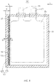
- FIG. 1 shows an electrochemical device 100 according to a first embodiment of this application.
- the electrochemical device 100 according to this embodiment of this application is a battery.
- the electrochemical device 100 may be a capacitive device (including at least one capacitive or pseudocapacitive electrode) or a hybrid device (including two different types of electrodes selected from a battery, an electrochemical double layer capacitor (EDLC), or a pseudocapacitive electrode).
- EDLC electrochemical double layer capacitor
- the electrochemical device 100 includes a housing 10, an electrode assembly 21, a positive tab 23, and a negative tab 25.
- An accommodation space 12 is formed in the housing 10.
- the electrode assembly 21 is located in the accommodation space 12.
- Both the positive tab 23 and the negative tab 25 are electrically connected to the electrode assembly 21 and protrude out of the housing 10.
- the positive tab 23 and the negative tab 25 are located on a same side of the housing 10.
- the housing 10 includes a first sealing edge 13 extending outward from one side of the accommodation space 12.
- the first sealing edge 13 is located on a different side of the housing 10 than the positive tab 23 and the negative tab 25.
- the side of the housing 10, on which the positive tab 23 and the negative tab 25 are located, may be sealed by a commonly used sealing method such as heat sealing.
- the first sealing edge 13 may be located on the same side of the housing 10 as the positive tab 23 and the negative tab 25.
- the first sealing edge 13 is configured to seal the positive tab 23 and the negative tab 25, so as to increase sealing strength on the tab side and enhance the safety performance of the electrochemical device.
- the first sealing edge 13 includes a first sealing film 30 and a second sealing film 90 disposed opposite to each other.
- the first sealing film 30 and the second sealing film 90 are of the same structure, and may be an aluminum plastic film, a steel plastic film, or the like.
- the first sealing film 30 and the second sealing film 90 may be of different structures.
- the first sealing film 30 includes a metal foil layer 31, and a protection layer 32 and a hot-pressing layer 33 that are disposed on two opposite sides of the metal foil layer 31 respectively.
- the protection layer 32 is located on the outer side of the housing 10 for a purpose of external protection, and may be made of an insulation material such as nylon.
- the metal foil layer 31 is configured to maintain mechanical strength and block moisture, and may be an aluminum foil layer or a steel foil layer. With thermal bonding properties, the heat-pressing layer 33 serves a purpose of sealing, and is located on the inner side of the housing 10.
- the hot-pressing layer 33 may be made of polypropylene (polypropylene, PP).
- a direction from a side of the first sealing edge 13 close to the accommodation space 12 to a side away from the accommodation space 12 is defined as a first direction L.
- the first sealing film 30 includes a first seal region 132 and a second seal region 134 that are connected to each other.
- the second sealing film 90 includes a third seal region 135 and a fourth seal region 136 that are connected to each other. Two neighboring surfaces of the first seal region 132 and the third seal region 135 fit closely with each other so that the first seal region 132 and the third seal region 135 combine to form the second sealing region 131.
- Two neighboring surfaces of the second seal region 134 and the fourth seal region 136 fit closely with each other so that the second seal region 134 and the fourth seal region 136 combine to form the first sealing region 133.
- the hot-pressing layer located in the second seal region 134 is connected to the hot-pressing layer located in the fourth seal region 136 in a close fitting manner.
- the thickness of the first sealing region 133 keeps equal in all parts, the thickness of any part of the second sealing region 131 is greater than the thickness of the first sealing region 133, and the thickness of any part of the accommodation space 12 is greater than a maximum thickness of the second sealing region 131.
- a first imprint 51 is formed between the first sealing region 133 and the second sealing region 131.
- a second imprint 53 is formed between the second sealing region 131 and the accommodation space 12.
- the overflow adhesive 40 means an adhesive hardened after the adhesive overflows from the first sealing region 133 and the second sealing region 132 into the accommodation space 12 during sealing.
- the adhesive formed by melting the hot-pressing layer 33 located in the first sealing region 133 and the second sealing region 132 enters the accommodation space 12 along the inner surfaces of the first sealing film 30 and the second sealing film 90 under a pressure of the seal head, so as to form the overflow adhesive 40.
- the overflow adhesive 40 is connected to the second sealing region 132 and partly fills in the accommodation space 12.
- the side of the overflow adhesive 40 away from the sealing region 133 is recessed along the first direction L.
- a width of the first sealing region 133 is W 1 (mm), and a width of the second sealing region 131 is W 2 (mm).
- a ratio of W 2 to W 1 is 0.01 to 0.5.
- the width of the second sealing region 131 is deficient, the overflow adhesive 40 is generated in a relatively large amount, and the space is not enough to accommodate the adhesive that overflows out of the first sealing region 133.
- the overflowing adhesive is accumulated in the first sealing region 133 to form a stress concentration point.
- the width of the first sealing region 133 is deficient and may affect the sealing strength of the first sealing edge 13, thereby impairing the life of the seal.
- a thickness of the first sealing film 30 is To (mm)
- a thickness of the first sealing region 133 is H 0 (mm)
- a maximum thickness of the second sealing region 131 is H 1 (mm).
- a ratio of H 1 to H 0 is 1 to 10.
- the ratio of H 1 to H 0 is less than 1, it indicates that the adhesive melted and overflowing out of the first sealing region 133 during sealing is deficient and may lead to untight sealing, thereby failing to achieve a good bonding and sealing effect.
- the ratio of H 1 to H 0 is greater than 10, it indicates that the adhesive melted and overflowing out of the first sealing region 133 during sealing is excessive.
- a large amount of overflowing adhesive accumulates in the accommodation space 12 to form a stress concentration point.
- the electrochemical device 100 drops, vibrates, or the like, the housing 10 is prone to rupture, and the item contained in the housing 10, such as an electrolytic solution, is at risk of leaking.
- the cross-sectional area S (mm 2 ) of the overflow adhesive 40 along the thickness direction H of the first sealing edge 13 satisfies the following formula: (2 ⁇ T 0 - H 1 ) ⁇ (W 1 + W 2 ) ⁇ S ⁇ (2 ⁇ T 0 - H 0 ) ⁇ (W 1 + W 2 ).
- the cross-sectional area of the overflow adhesive 40 in this application falls between (i) a cross-sectional area of the adhesive that overflows when the first sealing edge 13 includes only the first sealing region 133 (the width of the first sealing region 133 along the first direction L is equal to the width of the first sealing edge 13) and (ii) a cross-sectional area of the adhesive that overflows when the first sealing edge 13 includes only the second sealing region 131 (the width of the second sealing region 131 along the first direction L is equal to the width of the first sealing edge 13).
- the cross-sectional area S of the overflow adhesive 40 starts from a point at which the thickness of the accommodation space 12 begins to be greater than the thickness of the first sealing edge 13.
- S As tested, if S is excessive, it indicates that a large amount of adhesive overflowing from the first sealing edge 13 flows into the accommodation space 12. However, the accommodation space 12 is not enough to accommodate a large amount of overflowing adhesive. The large amount of overflowing adhesive accumulates in the accommodation space 12 to form a stress concentration point. In a case that the electrochemical device 100 drops, vibrates, or the like, the housing 10 is prone to rupture, and the item contained in the housing 10, such as the electrolytic solution, is at risk of leaking. If S is deficient, it indicates that the adhesive flowing from the first sealing edge 13 into the accommodation space 12 is deficient, and fails to achieve a good bonding and sealing effect.
- a tensile sealing force of both the first sealing region 133 and the second sealing region 131 is 1 to 10 N/mm. If the tensile sealing force is deficient, the sealing strength of the sealing region is insufficient.
- an upper limit of the tensile sealing force of the sealing region may be an upper limit of a tensile force of the housing 10.
- an electrochemical device 200 according to a second embodiment of this application is almost the same as the electrochemical device 100 according to the first embodiment, but differs in that the housing 10 further includes a second sealing edge 14 that protrudes outward from one side of the accommodation space 12.
- the second sealing edge 14 and the first sealing edge 13 are located on two neighboring sides of the housing 10 respectively and are connected to each other.
- the second sealing edge 14 and the first sealing edge 13 may be located on two opposite sides of the housing 10 respectively instead, without being connected to each other.
- the second sealing edge 14 and the first sealing edge 13 may be of the same structure.
- the second sealing edge 14 includes a third sealing film and a fourth sealing film disposed opposite to each other.
- the third sealing film and the fourth sealing film are of the same structure, and may be an aluminum plastic film, a steel plastic film, or the like.
- the third sealing film and the fourth sealing film may be of different structures.
- the third sealing film includes a metal foil layer, and a protection layer and a hot-pressing layer that are disposed on two opposite sides of the metal foil layer respectively.
- a direction from a side of the second sealing edge 14 close to the accommodation space 12 to a side away from the accommodation space 12 is defined as a second direction M.
- the third sealing film includes a fifth seal region (not shown) and a sixth seal region (not shown) that are connected to each other
- the fourth sealing film includes a seventh seal region (not shown) and an eighth seal region (not shown) that are connected to each other.
- a third imprint 147 is formed between the third sealing region 145 and the fourth sealing region 146.
- a fourth imprint 148 is formed between the fourth sealing region 146 and the accommodation space 12. In a thickness direction of the second sealing edge 14, a thickness of the third sealing region 145 is less than a thickness of the fourth sealing region 146.
- an electrochemical device 300 according to a third embodiment of this application is almost the same as the electrochemical device 200 according to the second embodiment, but differs in that the housing 300 further includes a third sealing edge 15 that protrudes outward from one side of the accommodation space 12.
- the third sealing edge 15 and the first sealing edge 13 are located on two opposite sides of the housing 10 respectively, and the second sealing edge 14 is connected to the first sealing edge 13 and the third sealing edge 15.
- the third sealing edge 15 and the first sealing edge 13 are of the same structure.
- the third sealing edge 15 includes a fifth sealing film and a sixth sealing film disposed opposite to each other.
- the fifth sealing film and the sixth sealing film are of the same structure, and may be an aluminum plastic film, a steel plastic film, or the like.
- the fifth sealing film and the sixth sealing film may be of different structures.
- the fifth sealing film includes a metal foil layer, and a protection layer and a hot-pressing layer that are disposed on two opposite sides of the metal foil layer respectively.
- a direction from a side of the third sealing edge 15 close to the accommodation space 12 to a side away from the accommodation space 12 is defined as a third direction N.
- the fifth sealing film includes a ninth seal region (not shown) and a tenth seal region (not shown) that are connected to each other.
- the sixth sealing film includes an eleventh seal region (not shown) and a twelfth seal region (not shown) that are connected to each other.
- a fifth imprint 155 is formed between the fifth sealing region 153 and the sixth sealing region 154.
- a sixth imprint 156 is formed between the sixth sealing region 154 and the accommodation space 12. In a thickness direction of the third sealing edge 15, a thickness of the fifth sealing region 153 is less than a thickness of the sixth sealing region 154.
- an electrochemical device 400 according to a fourth embodiment of this application is almost the same as the electrochemical device 100 according to the first embodiment, but differs in that the positive tab 23 and the negative tab 25 are located on two opposite sides of the housing 10 respectively.
- the positive tab 23 and the negative tab 25 may be located on neighboring sides of the housing 10 respectively instead.
- an electrochemical device 500 according to a fifth embodiment of this application is almost the same as the electrochemical device 100 according to the first embodiment, but differs in that the first sealing edge 13 further includes an overflow region 137.
- the overflow region 137 is located on a side of the seal region 133 away from the overflow area 131.
- the overflow region 137 is filled with the overflow adhesive 52.
- the first sealing edge 13 may further include a third sealing region disposed on a side of the first sealing region 133 away from the second sealing region 131.
- the third sealing region and the second sealing region 131 may be of the same structure.
- the housing 10 is sealed by an upper seal head 60 and a lower seal head 70.
- the upper seal head 60 and the lower seal head 70 each include a sealing face 80.
- the sealing face 80 includes a seal-head first seal region 81 corresponding to the first sealing region 133 of the housing 10 and a seal-head second seal region 83 corresponding to the second sealing region 131.
- the seal-head second seal region 83 is recessed against the seal-head first seal region 81.
- the sealing face located in the seal-head first seal region 81 is a flat face.
- the sealing face located in the seal-head second seal region 83 is a stepped face.
- the shape of the sealing face located in the seal-head second seal region 83 matches the shape of the second sealing region 131 of the first sealing edge 13.
- a width of the seal-head second seal region 83 is equal to a width of the second sealing region 131.
- the sealing face located in the seal-head second seal region 83 may be an arc face, a beveled face, or the like instead, as long as the cross-sectional area S of the overflow adhesive 40 formed in the overflow region 137 after completion of sealing the housing 10 satisfies the following formula: (2 ⁇ T 0 - H 1 ) ⁇ (W 1 + W 2 ) ⁇ S ⁇ (2 ⁇ T 0 - H 0 ) ⁇ (W 1 + W 2 ).
- the sealing face 80 of the upper seal head 60 or the lower seal head 70 includes the seal-head first seal region 81 and the seal-head second seal region 83, and the sealing face of the other seal head is a flat face.
- the second sealing region 131 is formed by just disposing the first seal region 132 and the second seal region 134 in a non-parallel manner or disposing the third seal region 135 and the fourth seal region 136 in a non-parallel manner.
- An embodiment of this application further provides an electronic device containing the electrochemical device 100.
- the electronic device may be any known electronic device, for example, a mobile phone, a computer, a wearable device, an unmanned aerial vehicle, an energy storage device, an electric tool, and an electric vehicle.
Landscapes
- Engineering & Computer Science (AREA)
- Power Engineering (AREA)
- Chemical & Material Sciences (AREA)
- Chemical Kinetics & Catalysis (AREA)
- Electrochemistry (AREA)
- General Chemical & Material Sciences (AREA)
- Microelectronics & Electronic Packaging (AREA)
- Sealing Battery Cases Or Jackets (AREA)
- Electric Double-Layer Capacitors Or The Like (AREA)
- Battery Mounting, Suspending (AREA)
Abstract
Description
- This application relates to the technical field of energy storage, and in particular, to an electrochemical device and an electronic device containing the electrochemical device.
- An electrochemical device (such as a pouch-type battery) is hermetically packaged in a packaging bag (such as aluminum plastic film or a steel plastic film). In sealing the packaging bag (for example, by heat sealing or glue sealing), the glue at a sealing position is squeezed toward both sides. A relatively large overflow point occurs on an inner side and an outer side of a sealing imprint formed (at the sealing position). In a case that the electrochemical device drops, vibrates, or the like, stress concentration may occur at the large overflow point. At this point, the packaging bag is prone to rupture, and even prone to electrolyte leakage, thereby affecting safety performance of the electrochemical device.
- In view of disadvantages of the prior art described above, this application provides an electrochemical device that alleviates the problem of stress concentration at an overflow point.
- An embodiment of this application provides an electrochemical device. The electrochemical device includes an electrode assembly and a housing. The housing forms an accommodation space configured to accommodate the electrode assembly. The housing includes a first sealing edge. The first sealing edge includes a first sealing film and a second sealing film. A direction from a side of the first sealing edge close to the accommodation space to a side away from the accommodation space is defined as a first direction. Along the first direction, the first sealing film includes a first seal region and a second seal region that are connected to each other, and the second sealing film includes a third seal region and a fourth seal region that are connected to each other. The second seal region and the fourth seal region combine to form a first sealing region. The first seal region and the third seal region combine to form a second sealing region. In a thickness direction of the first sealing edge, a thickness of the first sealing region is less than a thickness of the second sealing region.
- In the electrochemical device according to this embodiment of this application, by disposing the first sealing region and the second sealing region in the first sealing edge, it is avoided that the overflow adhesive generated during the sealing from accumulating in the accommodation space, thereby alleviating the problem of stress concentration. In this way, the housing of the electrochemical device is not prone to rupture in the case of drop, vibration, and the like, and safety performance of the battery is improved.
- Optionally, a first imprint is formed between the first sealing region and the second sealing region. A second imprint is formed between the second sealing region and the accommodation space.
- Optionally, the electrochemical device further includes an overflow adhesive. The overflow adhesive is connected to the second sealing region and is accommodated in the accommodation space. Along the first direction, a width of the first sealing region is W1 (mm), and a width of the second sealing region is W2 (mm). In the thickness direction of the first sealing edge, a thickness of the first sealing film is T0 (mm), the thickness of the first sealing region is H0 (mm), and a maximum thickness of the second sealing region is H1 (mm). A cross-sectional area S (mm2) of the overflow adhesive along the thickness direction of the first sealing edge satisfies the following formula: (2 × T0 - H1) × (W1 + W2) < S < (2 × T0 - H0) × (W1 + W2).
- If the cross-sectional area S of the overflow adhesive is excessive, the overflow adhesive forms a stress concentration point by accumulating. If the cross-sectional area S of the overflow adhesive is deficient, the amount of the overflow adhesive in an overflow region is small, and the overflow region fails to achieve a good sealing effect. By controlling the cross-sectional area of the overflow adhesive formed in the overflow region, the amount of adhesive that overflows in the sealing region during the sealing can be equalized. This not only avoids a stress concentration point formed by accumulation of a large amount of overflow adhesive in the overflow region, but also ensures sealing strength of the overflow region, and achieves excellent sealing reliability of the electrochemical device.
- Optionally, the ratio of W2 to W1 is 0.01 to 0.5, thereby further equalizing the amount of adhesive that overflows in the sealing region during sealing, and enhancing the sealing strength.
- Optionally, the ratio of H1 to H0 is 1 to 10, thereby further equalizing the amount of adhesive that overflows in the sealing region during sealing, and enhancing the sealing strength.
- Optionally, a tensile sealing force of both the first sealing region and the second sealing region is 1 to 10 N/mm, so that the housing achieves relatively high strength.
- Optionally, the electrochemical device further includes a first tab. The first tab is electrically connected to the electrode assembly and protrudes from one side of the housing, and the first sealing edge and the first tab are located on a same side of the electrochemical device. The sealing strength on a tab side of the electrochemical device is usually the lowest. That the first sealing edge and the first tab are located on the same side of the electrochemical device helps to increase the sealing strength on the first tab side and improve the safety performance of the electrochemical device.
- Optionally, the housing further includes a second sealing edge. The second sealing edge is connected to or disconnected from the first sealing edge. The second sealing edge includes a third sealing film and a fourth sealing film. A direction from a side of the second sealing edge close to the accommodation space to a side away from the accommodation space is defined as a second direction. Along the second direction, the third sealing film includes a fifth seal region and a sixth seal region that are connected to each other, and the fourth sealing film includes a seventh seal region and an eighth seal region that are connected to each other. The sixth seal region and the eighth seal region combine to form a third sealing region. The fifth seal region and the seventh seal region combine to form a fourth sealing region. In a thickness direction of the second sealing edge, a thickness of the third sealing region is less than a thickness of the fourth sealing region.
- The second sealing edge and the first sealing edge may have the same sealing structure. With a plurality of sealing edges disposed, the sealing safety of the electrochemical device can be further improved.
- Optionally, the housing further includes a third sealing edge. The third sealing edge is connected to the first sealing edge or the second sealing edge. The third sealing edge includes a fifth sealing film and a sixth sealing film. A direction from a side of the third sealing edge close to the accommodation space to a side away from the accommodation space is defined as a third direction. Along the third direction, the fifth sealing film includes a ninth seal region and a tenth seal region that are connected to each other. The sixth sealing film includes an eleventh seal region and a twelfth seal region that are connected to each other. The tenth seal region and the twelfth seal region combine to form a fifth sealing region, and the ninth seal region and the eleventh seal region combine to form a sixth sealing region. In a thickness direction of the third sealing edge, a thickness of the fifth sealing region is less than a thickness of the sixth sealing region.
- The third sealing edge and the first sealing edge may have the same sealing structure, so as to further improve the sealing safety of the electrochemical device.
- Optionally, the electrochemical device further includes a positive tab and a negative tab. Both the positive tab and the negative tab are electrically connected to the electrode assembly, and protrude out of the housing, and are located on the same side or different sides of the housing.
- An embodiment of this application further provides an electronic device containing the electrochemical device.
- To describe the technical solutions in the embodiments of this application or the prior art more clearly, the following outlines the drawings to be used in the description of the embodiments of this application or the prior art. Evidently, the drawings outlined below are merely a part of embodiments of this application, and a person of ordinary skill in the art may derive other drawings from the outlined drawings without making any creative efforts.
-
FIG. 1 is a schematic structural diagram of an electrochemical device according to a first embodiment of this application; -
FIG. 2 is a sectional view of the electrochemical device shown inFIG. 1 and sectioned along a line II-II; -
FIG. 3 is a schematic structural diagram of an electrochemical device according to a second embodiment of this application; -
FIG. 4 is a schematic structural diagram of an electrochemical device according to a third embodiment of this application; -
FIG. 5 is a schematic structural diagram of an electrochemical device according to a fourth embodiment of this application; -
FIG. 6 is a local sectional view of an electrochemical device according to a fifth embodiment of this application; and -
FIG. 7 is a schematic structural diagram of a seal head and an electrochemical device according to an embodiment of this application. - Reference numerals of main components:
-
Electrochemical device -
Housing 10 -
Electrode assembly 21 -
Positive tab 23 -
Negative tab 25 -
Accommodation space 12 - First sealing
edge 13 - Second sealing
edge 14 - Third sealing
edge 15 - First sealing
film 30 -
First seal region 132 -
Second seal region 134 - Second sealing film 90
-
Third seal region 135 -
Fourth seal region 136 -
Metal foil layer 31 -
Protection layer 32 - Hot-pressing
layer 33 -
Second sealing region 131 -
Overflow region 137 - First sealing
region 133 -
Overflow adhesive -
Upper seal head 60 -
Lower seal head 70 - Sealing
face 80 - First seal region of the
seal head 81 - Second seal region of the
seal head 83 -
First imprint 51 -
Second imprint 53 -
Third sealing region 145 -
Fourth sealing region 146 -
Third imprint 147 -
Fourth imprint 148 -
Fifth sealing region 153 - Sixth sealing
region 154 -
Fifth imprint 155 -
Sixth imprint 156 - This application is further described below with reference to the following specific embodiments and the foregoing drawings.
- The following describes the technical solutions in the embodiments of this application clearly and thoroughly with reference to the drawings herein. Evidently, the described embodiments are merely a part of but not all of the embodiments of this application. All other embodiments derived by a person of ordinary skill in the art based on the embodiments of the present invention without making any creative effort fall within the protection scope of the present invention.
- It is hereby noted that a component referred to as being "connected to" another component may be directly connected to the other component or may be connected to the other component through an intermediate component. A component considered to be "disposed on" another component may be directly disposed on the other component or may be disposed on the other component through an intermediate component. Unless otherwise defined, all technical and scientific terms used herein have the same meanings as usually understood by a person skilled in the technical field of this application. The terms "outer side" and "inner side" used in embodiments of this application are intended merely for ease of describing specific embodiments but not intended to limit this application.
- Referring to
FIG. 1, FIG. 1 shows anelectrochemical device 100 according to a first embodiment of this application. Theelectrochemical device 100 according to this embodiment of this application is a battery. Optionally, in other embodiments, theelectrochemical device 100 may be a capacitive device (including at least one capacitive or pseudocapacitive electrode) or a hybrid device (including two different types of electrodes selected from a battery, an electrochemical double layer capacitor (EDLC), or a pseudocapacitive electrode). - The
electrochemical device 100 includes ahousing 10, anelectrode assembly 21, apositive tab 23, and anegative tab 25. Anaccommodation space 12 is formed in thehousing 10. Theelectrode assembly 21 is located in theaccommodation space 12. Both thepositive tab 23 and thenegative tab 25 are electrically connected to theelectrode assembly 21 and protrude out of thehousing 10. Thepositive tab 23 and thenegative tab 25 are located on a same side of thehousing 10. - The
housing 10 includes afirst sealing edge 13 extending outward from one side of theaccommodation space 12. Thefirst sealing edge 13 is located on a different side of thehousing 10 than thepositive tab 23 and thenegative tab 25. The side of thehousing 10, on which thepositive tab 23 and thenegative tab 25 are located, may be sealed by a commonly used sealing method such as heat sealing. - Optionally, the
first sealing edge 13 may be located on the same side of thehousing 10 as thepositive tab 23 and thenegative tab 25. Thefirst sealing edge 13 is configured to seal thepositive tab 23 and thenegative tab 25, so as to increase sealing strength on the tab side and enhance the safety performance of the electrochemical device. - Referring to
FIG. 2 , thefirst sealing edge 13 includes afirst sealing film 30 and a second sealing film 90 disposed opposite to each other. Thefirst sealing film 30 and the second sealing film 90 are of the same structure, and may be an aluminum plastic film, a steel plastic film, or the like. - Optionally, in other embodiments, the
first sealing film 30 and the second sealing film 90 may be of different structures. For example, in a pouch-type battery, thefirst sealing film 30 includes ametal foil layer 31, and aprotection layer 32 and a hot-pressinglayer 33 that are disposed on two opposite sides of themetal foil layer 31 respectively. Theprotection layer 32 is located on the outer side of thehousing 10 for a purpose of external protection, and may be made of an insulation material such as nylon. Themetal foil layer 31 is configured to maintain mechanical strength and block moisture, and may be an aluminum foil layer or a steel foil layer. With thermal bonding properties, the heat-pressinglayer 33 serves a purpose of sealing, and is located on the inner side of thehousing 10. The hot-pressinglayer 33 may be made of polypropylene (polypropylene, PP). - A direction from a side of the
first sealing edge 13 close to theaccommodation space 12 to a side away from theaccommodation space 12 is defined as a first direction L. Along the first direction L, thefirst sealing film 30 includes afirst seal region 132 and asecond seal region 134 that are connected to each other. The second sealing film 90 includes athird seal region 135 and afourth seal region 136 that are connected to each other. Two neighboring surfaces of thefirst seal region 132 and thethird seal region 135 fit closely with each other so that thefirst seal region 132 and thethird seal region 135 combine to form thesecond sealing region 131. Two neighboring surfaces of thesecond seal region 134 and thefourth seal region 136 fit closely with each other so that thesecond seal region 134 and thefourth seal region 136 combine to form thefirst sealing region 133. In other words, the hot-pressing layer located in thesecond seal region 134 is connected to the hot-pressing layer located in thefourth seal region 136 in a close fitting manner. - Along the first direction L, the thickness of the
first sealing region 133 keeps equal in all parts, the thickness of any part of thesecond sealing region 131 is greater than the thickness of thefirst sealing region 133, and the thickness of any part of theaccommodation space 12 is greater than a maximum thickness of thesecond sealing region 131. Referring toFIG. 1 , afirst imprint 51 is formed between thefirst sealing region 133 and thesecond sealing region 131. Asecond imprint 53 is formed between thesecond sealing region 131 and theaccommodation space 12. - An
overflow adhesive 40 is accommodated in theaccommodation space 12. In this application, theoverflow adhesive 40 means an adhesive hardened after the adhesive overflows from thefirst sealing region 133 and thesecond sealing region 132 into theaccommodation space 12 during sealing. When thehousing 10 is being sealed such as heat-sealed, the adhesive formed by melting the hot-pressinglayer 33 located in thefirst sealing region 133 and thesecond sealing region 132 enters theaccommodation space 12 along the inner surfaces of thefirst sealing film 30 and the second sealing film 90 under a pressure of the seal head, so as to form theoverflow adhesive 40. Theoverflow adhesive 40 is connected to thesecond sealing region 132 and partly fills in theaccommodation space 12. The side of theoverflow adhesive 40 away from the sealingregion 133 is recessed along the first direction L. - In an embodiment, along the first direction L, a width of the
first sealing region 133 is W1 (mm), and a width of thesecond sealing region 131 is W2 (mm). Optionally, a ratio of W2 to W1 is 0.01 to 0.5. - As tested, when the ratio of W2 to W1 is less than 0.01, the width of the
second sealing region 131 is deficient, theoverflow adhesive 40 is generated in a relatively large amount, and the space is not enough to accommodate the adhesive that overflows out of thefirst sealing region 133. The overflowing adhesive is accumulated in thefirst sealing region 133 to form a stress concentration point. When the ratio of W2 to W1 is greater than 0.5, the width of thefirst sealing region 133 is deficient and may affect the sealing strength of thefirst sealing edge 13, thereby impairing the life of the seal. - In an embodiment, along the thickness direction H of the
first sealing edge 13, a thickness of thefirst sealing film 30 is To (mm), a thickness of thefirst sealing region 133 is H0 (mm), and a maximum thickness of thesecond sealing region 131 is H1 (mm). Optionally, a ratio of H1 to H0 is 1 to 10. - As tested, when the ratio of H1 to H0 is less than 1, it indicates that the adhesive melted and overflowing out of the
first sealing region 133 during sealing is deficient and may lead to untight sealing, thereby failing to achieve a good bonding and sealing effect. When the ratio of H1 to H0 is greater than 10, it indicates that the adhesive melted and overflowing out of thefirst sealing region 133 during sealing is excessive. A large amount of overflowing adhesive accumulates in theaccommodation space 12 to form a stress concentration point. When theelectrochemical device 100 drops, vibrates, or the like, thehousing 10 is prone to rupture, and the item contained in thehousing 10, such as an electrolytic solution, is at risk of leaking. - In an embodiment, the cross-sectional area S (mm2) of the
overflow adhesive 40 along the thickness direction H of thefirst sealing edge 13 satisfies the following formula: (2 × T0 - H1) × (W1 + W2) < S < (2 × T0 - H0) × (W1 + W2). - To be specific, the cross-sectional area of the
overflow adhesive 40 in this application falls between (i) a cross-sectional area of the adhesive that overflows when thefirst sealing edge 13 includes only the first sealing region 133 (the width of thefirst sealing region 133 along the first direction L is equal to the width of the first sealing edge 13) and (ii) a cross-sectional area of the adhesive that overflows when thefirst sealing edge 13 includes only the second sealing region 131 (the width of thesecond sealing region 131 along the first direction L is equal to the width of the first sealing edge 13). The cross-sectional area S of the overflow adhesive 40 starts from a point at which the thickness of theaccommodation space 12 begins to be greater than the thickness of thefirst sealing edge 13. - As tested, if S is excessive, it indicates that a large amount of adhesive overflowing from the
first sealing edge 13 flows into theaccommodation space 12. However, theaccommodation space 12 is not enough to accommodate a large amount of overflowing adhesive. The large amount of overflowing adhesive accumulates in theaccommodation space 12 to form a stress concentration point. In a case that theelectrochemical device 100 drops, vibrates, or the like, thehousing 10 is prone to rupture, and the item contained in thehousing 10, such as the electrolytic solution, is at risk of leaking. If S is deficient, it indicates that the adhesive flowing from thefirst sealing edge 13 into theaccommodation space 12 is deficient, and fails to achieve a good bonding and sealing effect. - Optionally, a tensile sealing force of both the
first sealing region 133 and thesecond sealing region 131 is 1 to 10 N/mm. If the tensile sealing force is deficient, the sealing strength of the sealing region is insufficient. Optionally, an upper limit of the tensile sealing force of the sealing region may be an upper limit of a tensile force of thehousing 10. - Referring to
FIG. 3 , anelectrochemical device 200 according to a second embodiment of this application is almost the same as theelectrochemical device 100 according to the first embodiment, but differs in that thehousing 10 further includes asecond sealing edge 14 that protrudes outward from one side of theaccommodation space 12. Thesecond sealing edge 14 and thefirst sealing edge 13 are located on two neighboring sides of thehousing 10 respectively and are connected to each other. Optionally, thesecond sealing edge 14 and thefirst sealing edge 13 may be located on two opposite sides of thehousing 10 respectively instead, without being connected to each other. - Optionally, the
second sealing edge 14 and thefirst sealing edge 13 may be of the same structure. Thesecond sealing edge 14 includes a third sealing film and a fourth sealing film disposed opposite to each other. The third sealing film and the fourth sealing film are of the same structure, and may be an aluminum plastic film, a steel plastic film, or the like. Optionally, in other embodiments, the third sealing film and the fourth sealing film may be of different structures. In a pouch-type battery, the third sealing film includes a metal foil layer, and a protection layer and a hot-pressing layer that are disposed on two opposite sides of the metal foil layer respectively. - A direction from a side of the
second sealing edge 14 close to theaccommodation space 12 to a side away from theaccommodation space 12 is defined as a second direction M. Along the second direction M, the third sealing film includes a fifth seal region (not shown) and a sixth seal region (not shown) that are connected to each other, and the fourth sealing film includes a seventh seal region (not shown) and an eighth seal region (not shown) that are connected to each other. - Two neighboring surfaces of the sixth seal region and the eighth seal region fit closely with each other so that the sixth seal region and the eighth seal region combine to form the
third sealing region 145. Two neighboring surfaces of the fifth seal region and the seventh seal region fit closely with each other so that the fifth seal region and the seventh seal region combine to form thefourth sealing region 146. Athird imprint 147 is formed between thethird sealing region 145 and thefourth sealing region 146. Afourth imprint 148 is formed between thefourth sealing region 146 and theaccommodation space 12. In a thickness direction of thesecond sealing edge 14, a thickness of thethird sealing region 145 is less than a thickness of thefourth sealing region 146. - Referring to
FIG. 4 , anelectrochemical device 300 according to a third embodiment of this application is almost the same as theelectrochemical device 200 according to the second embodiment, but differs in that thehousing 300 further includes athird sealing edge 15 that protrudes outward from one side of theaccommodation space 12. Thethird sealing edge 15 and thefirst sealing edge 13 are located on two opposite sides of thehousing 10 respectively, and thesecond sealing edge 14 is connected to thefirst sealing edge 13 and thethird sealing edge 15. - Optionally, the
third sealing edge 15 and thefirst sealing edge 13 are of the same structure. Thethird sealing edge 15 includes a fifth sealing film and a sixth sealing film disposed opposite to each other. The fifth sealing film and the sixth sealing film are of the same structure, and may be an aluminum plastic film, a steel plastic film, or the like. Optionally, in other embodiments, the fifth sealing film and the sixth sealing film may be of different structures. In a pouch-type battery, the fifth sealing film includes a metal foil layer, and a protection layer and a hot-pressing layer that are disposed on two opposite sides of the metal foil layer respectively. - A direction from a side of the
third sealing edge 15 close to theaccommodation space 12 to a side away from theaccommodation space 12 is defined as a third direction N. Along the third direction N, the fifth sealing film includes a ninth seal region (not shown) and a tenth seal region (not shown) that are connected to each other. The sixth sealing film includes an eleventh seal region (not shown) and a twelfth seal region (not shown) that are connected to each other. - Two neighboring surfaces of the tenth seal region and the twelfth seal region fit closely with each other so that the tenth seal region and the twelfth seal region combine to form the
fifth sealing region 153. Two neighboring surfaces of the ninth seal region and the eleventh seal region fit closely with each other so that the ninth seal region and the eleventh seal region combine to form thesixth sealing region 154. Afifth imprint 155 is formed between thefifth sealing region 153 and thesixth sealing region 154. Asixth imprint 156 is formed between thesixth sealing region 154 and theaccommodation space 12. In a thickness direction of thethird sealing edge 15, a thickness of thefifth sealing region 153 is less than a thickness of thesixth sealing region 154. - Referring to
FIG. 5 , anelectrochemical device 400 according to a fourth embodiment of this application is almost the same as theelectrochemical device 100 according to the first embodiment, but differs in that thepositive tab 23 and thenegative tab 25 are located on two opposite sides of thehousing 10 respectively. Optionally, thepositive tab 23 and thenegative tab 25 may be located on neighboring sides of thehousing 10 respectively instead. - Referring to
FIG. 6 , anelectrochemical device 500 according to a fifth embodiment of this application is almost the same as theelectrochemical device 100 according to the first embodiment, but differs in that thefirst sealing edge 13 further includes anoverflow region 137. Theoverflow region 137 is located on a side of theseal region 133 away from theoverflow area 131. Theoverflow region 137 is filled with theoverflow adhesive 52. Optionally, in other embodiments, thefirst sealing edge 13 may further include a third sealing region disposed on a side of thefirst sealing region 133 away from thesecond sealing region 131. The third sealing region and thesecond sealing region 131 may be of the same structure. - Referring to
FIG. 7 , in an embodiment, thehousing 10 is sealed by anupper seal head 60 and alower seal head 70. Theupper seal head 60 and thelower seal head 70 each include a sealingface 80. The sealingface 80 includes a seal-headfirst seal region 81 corresponding to thefirst sealing region 133 of thehousing 10 and a seal-headsecond seal region 83 corresponding to thesecond sealing region 131. The seal-headsecond seal region 83 is recessed against the seal-headfirst seal region 81. The sealing face located in the seal-headfirst seal region 81 is a flat face. The sealing face located in the seal-headsecond seal region 83 is a stepped face. The shape of the sealing face located in the seal-headsecond seal region 83 matches the shape of thesecond sealing region 131 of thefirst sealing edge 13. Along the first direction L, a width of the seal-headsecond seal region 83 is equal to a width of thesecond sealing region 131. Optionally, the sealing face located in the seal-headsecond seal region 83 may be an arc face, a beveled face, or the like instead, as long as the cross-sectional area S of theoverflow adhesive 40 formed in theoverflow region 137 after completion of sealing thehousing 10 satisfies the following formula: (2 × T0 - H1) × (W1 + W2) < S < (2 × T0 - H0) × (W1 + W2). - Optionally, only the sealing
face 80 of theupper seal head 60 or thelower seal head 70 includes the seal-headfirst seal region 81 and the seal-headsecond seal region 83, and the sealing face of the other seal head is a flat face. In this way, thesecond sealing region 131 is formed by just disposing thefirst seal region 132 and thesecond seal region 134 in a non-parallel manner or disposing thethird seal region 135 and thefourth seal region 136 in a non-parallel manner. - An embodiment of this application further provides an electronic device containing the
electrochemical device 100. The electronic device may be any known electronic device, for example, a mobile phone, a computer, a wearable device, an unmanned aerial vehicle, an energy storage device, an electric tool, and an electric vehicle. - The embodiments hereof are described in a progressive manner, and each embodiment focuses on differences from other embodiments. The part that is identical or similar between different embodiments may be learned by referring to the corresponding embodiment. The foregoing description of the disclosed embodiments enables any person skilled in the art to implement or use the technical solutions of this application. Various modifications to such embodiments are readily evident to a person skilled in the art. General principles defined herein may be implemented in other embodiments without departing from the spirit or scope of this application. Therefore, this application is not limited to the embodiments shown, but is to be accorded the widest scope consistent with the principles and novel features disclosed herein.
Claims (10)
- An electrochemical device, comprising an electrode assembly and a housing, wherein the housing forms an accommodation space configured to accommodate the electrode assembly, the housing comprises a first sealing edge, and the first sealing edge comprises a first sealing film and a second sealing film;a direction from a side of the first sealing edge close to the accommodation space to a side away from the accommodation space is defined as a first direction, and, along the first direction, the first sealing film comprises a first seal region and a second seal region that are connected to each other, and the second sealing film comprises a third seal region and a fourth seal region that are connected to each other; andthe second seal region and the fourth seal region combine to form a first sealing region, the first seal region and the third seal region combine to form a second sealing region, and, in a thickness direction of the first sealing edge, a thickness of the first sealing region is less than a thickness of the second sealing region.
- The electrochemical device according to claim 1, wherein a first imprint is formed between the first sealing region and the second sealing region, and a second imprint is formed between the second sealing region and the accommodation space.
- The electrochemical device according to claim 1, wherein the electrochemical device further comprises an overflow adhesive, the overflow adhesive is connected to the second sealing region and is accommodated in the accommodation space, and, along the first direction, a width of the first sealing region is W1 (mm), a width of the second sealing region is W2 (mm), and, in the thickness direction of the first sealing edge, a thickness of the first sealing film is To (mm), the thickness of the first sealing region is H0 (mm), and a maximum thickness of the second sealing region is H1 (mm); and
a cross-sectional area S (mm2) of the overflow adhesive along the thickness direction of the first sealing edge satisfies the following formula:
- The electrochemical device according to claim 3, wherein a ratio of W2 to W1 is 0.01 to 0.5.
- The electrochemical device according to claim 3, wherein a ratio of H1 to H0 is 1 to 10.
- The electrochemical device according to claim 1, wherein a tensile sealing force of both the first sealing region and the second sealing region is 1 to 10 N/mm.
- The electrochemical device according to claim 1, wherein the electrochemical device further comprises a first tab, the first tab is electrically connected to the electrode assembly and protrudes from one side of the housing, and the first sealing edge and the first tab are located on a same side of the electrochemical device.
- The electrochemical device according to claim 1, wherein the housing further comprises a second sealing edge, the second sealing edge is connected to or disconnected from the first sealing edge, and the second sealing edge comprises a third sealing film and a fourth sealing film;a direction from a side of the second sealing edge close to the accommodation space to a side away from the accommodation space is defined as a second direction, and, along the second direction, the third sealing film comprises a fifth seal region and a sixth seal region that are connected to each other, and the fourth sealing film comprises a seventh seal region and an eighth seal region that are connected to each other; andthe sixth seal region and the eighth seal region combine to form a third sealing region, the fifth seal region and the seventh seal region combine to form a fourth sealing region, and, in a thickness direction of the second sealing edge, a thickness of the third sealing region is less than a thickness of the fourth sealing region.
- The electrochemical device according to claim 8, wherein the housing further comprises a third sealing edge, the third sealing edge is connected to the first sealing edge or the second sealing edge, and the third sealing edge comprises a fifth sealing film and a sixth sealing film;a direction from a side of the third sealing edge close to the accommodation space to a side away from the accommodation space is defined as a third direction, and, along the third direction, the fifth sealing film comprises a ninth seal region and a tenth seal region that are connected to each other, and the sixth sealing film comprises an eleventh seal region and a twelfth seal region that are connected to each other; andthe tenth seal region and the twelfth seal region combine to form a fifth sealing region, the ninth seal region and the eleventh seal region combine to form a sixth sealing region, and, in a thickness direction of the third sealing edge, a thickness of the fifth sealing region is less than a thickness of the sixth sealing region.
- An electronic device, comprising the electrochemical device according to any one of claims 1 to 9.
Applications Claiming Priority (1)
| Application Number | Priority Date | Filing Date | Title |
|---|---|---|---|
| PCT/CN2020/080969 WO2021189265A1 (en) | 2020-03-24 | 2020-03-24 | Electrochemical device and electronic device |
Publications (2)
| Publication Number | Publication Date |
|---|---|
| EP4113645A1 true EP4113645A1 (en) | 2023-01-04 |
| EP4113645A4 EP4113645A4 (en) | 2023-10-18 |
Family
ID=77413323
Family Applications (1)
| Application Number | Title | Priority Date | Filing Date |
|---|---|---|---|
| EP20927586.6A Pending EP4113645A4 (en) | 2020-03-24 | 2020-03-24 | Electrochemical device and electronic device |
Country Status (5)
| Country | Link |
|---|---|
| EP (1) | EP4113645A4 (en) |
| JP (1) | JP7570427B2 (en) |
| KR (1) | KR102837383B1 (en) |
| CN (1) | CN113330628B (en) |
| WO (1) | WO2021189265A1 (en) |
Families Citing this family (6)
| Publication number | Priority date | Publication date | Assignee | Title |
|---|---|---|---|---|
| CN114024103B (en) * | 2021-11-04 | 2024-06-11 | 宁德新能源科技有限公司 | Electrochemical devices and electronic devices |
| CN114709490B (en) * | 2022-03-24 | 2025-01-14 | 宁德新能源科技有限公司 | Electrochemical device and electricity-using device |
| CN114614174A (en) * | 2022-03-29 | 2022-06-10 | 东莞新能安科技有限公司 | Battery case, battery and electronic device |
| JP7821668B2 (en) * | 2022-03-31 | 2026-02-27 | 本田技研工業株式会社 | secondary battery |
| CN116435670B (en) * | 2023-06-12 | 2023-09-15 | 宁德新能源科技有限公司 | An electrochemical device and electrical equipment |
| CN120149665B (en) * | 2025-05-13 | 2025-08-19 | 浙江锂威电子科技有限公司 | Soft package battery and consumer |
Family Cites Families (17)
| Publication number | Priority date | Publication date | Assignee | Title |
|---|---|---|---|---|
| JP4432146B2 (en) | 1999-03-29 | 2010-03-17 | 株式会社ジーエス・ユアサコーポレーション | Nonaqueous electrolyte secondary battery |
| JP4498514B2 (en) * | 2000-01-18 | 2010-07-07 | 大日本印刷株式会社 | Battery container |
| JP2004055154A (en) * | 2002-07-16 | 2004-02-19 | Nissan Motor Co Ltd | Sealing structure and sealing treatment method for stacked battery |
| JP5793788B2 (en) | 2009-05-21 | 2015-10-14 | エルジー ケム. エルティーディ. | Water-resistant pouch-type secondary battery |
| JP2011204590A (en) | 2010-03-26 | 2011-10-13 | Nisshin Steel Co Ltd | Lithium-ion battery and heat-seal manufacturing method |
| WO2012030080A2 (en) * | 2010-08-30 | 2012-03-08 | 주식회사 엘지화학 | Rechargeable battery having a novel structure |
| JP5682778B2 (en) * | 2010-12-27 | 2015-03-11 | 日産自動車株式会社 | Fuel cell |
| JP5693327B2 (en) * | 2011-03-29 | 2015-04-01 | Fdk鳥取株式会社 | Method for producing electrochemical element |
| CN203103433U (en) * | 2012-12-25 | 2013-07-31 | 天津力神电池股份有限公司 | Visible packaging equipment of polymer lithium ion batteries |
| CN104584259B (en) | 2012-12-28 | 2017-03-15 | 株式会社Lg 化学 | Apparatus and method for the bag-shaped housing of sealed secondary battery |
| CN204088500U (en) * | 2014-08-21 | 2015-01-07 | 东莞新能源科技有限公司 | The packaging system of flexible packing lithium ion battery |
| KR102514594B1 (en) * | 2015-08-13 | 2023-03-27 | 삼성전자주식회사 | Exterior package for flexible electrochemical device and electrochemical device including the exterior package |
| JPWO2017158986A1 (en) | 2016-03-15 | 2019-01-17 | Necエナジーデバイス株式会社 | Battery cell |
| CN106058083A (en) * | 2016-08-19 | 2016-10-26 | 宁德时代新能源科技股份有限公司 | Laminate polymer battery shell and laminate polymer battery |
| CN106252578B (en) * | 2016-10-31 | 2019-01-08 | 宁德时代新能源科技股份有限公司 | Utmost point ear packaging structure and laminate polymer battery |
| JP7077081B2 (en) * | 2018-03-15 | 2022-05-30 | マクセル株式会社 | Electrochemical element |
| CN110391356B (en) * | 2018-04-19 | 2022-11-08 | 宁德新能源科技有限公司 | Battery with a battery cell |
-
2020
- 2020-03-24 EP EP20927586.6A patent/EP4113645A4/en active Pending
- 2020-03-24 CN CN202080007809.0A patent/CN113330628B/en active Active
- 2020-03-24 JP JP2022557991A patent/JP7570427B2/en active Active
- 2020-03-24 WO PCT/CN2020/080969 patent/WO2021189265A1/en not_active Ceased
- 2020-03-24 KR KR1020227034137A patent/KR102837383B1/en active Active
Also Published As
| Publication number | Publication date |
|---|---|
| KR102837383B1 (en) | 2025-07-24 |
| EP4113645A4 (en) | 2023-10-18 |
| WO2021189265A1 (en) | 2021-09-30 |
| KR20220140866A (en) | 2022-10-18 |
| CN113330628A (en) | 2021-08-31 |
| JP7570427B2 (en) | 2024-10-21 |
| JP2023518520A (en) | 2023-05-01 |
| CN113330628B (en) | 2022-11-11 |
Similar Documents
| Publication | Publication Date | Title |
|---|---|---|
| KR102837383B1 (en) | Electrochemical devices and electronic devices | |
| US8283067B2 (en) | Electric energy storage device and manufacturing method thereof | |
| CN102709054B (en) | Electrochemical device | |
| KR100973311B1 (en) | Battery pack | |
| CN110190316B (en) | Secondary battery | |
| JP2012124146A (en) | Secondary battery, battery unit, and battery module | |
| KR102773789B1 (en) | Secondary battery | |
| US7528573B2 (en) | Rechargeable battery having bare cell and protection circuit module | |
| CN113597702B (en) | Electrochemical device and electronic device | |
| KR20100126226A (en) | Water resistant pouch type secondary battery | |
| KR20140049654A (en) | Battery cell having electrode lead of improved resistance pressure and stability | |
| JP2006164784A (en) | Film-armored electric device | |
| JP2021118076A (en) | Power storage device | |
| CN209709099U (en) | Secondary battery | |
| KR20060097445A (en) | Secondary battery with improved safety by low melting adhesive resin | |
| CN112585799B (en) | Electric storage module and method of manufacturing electric storage module | |
| CN111194499B (en) | Power storage module | |
| JP7079681B2 (en) | Power storage module | |
| JP7079694B2 (en) | Power storage module | |
| CN113745630B (en) | Electrochemical device, method for manufacturing electrochemical device, and electronic device | |
| JP2022003625A (en) | Power storage device | |
| US12283721B2 (en) | Battery cell, battery module and vehicle | |
| US20240055692A1 (en) | Battery comprising a casing and an electrically insulating coating | |
| JP2020087587A (en) | Power storage module and manufacturing method of power storage module | |
| JP6913587B2 (en) | Power storage device |
Legal Events
| Date | Code | Title | Description |
|---|---|---|---|
| STAA | Information on the status of an ep patent application or granted ep patent |
Free format text: STATUS: THE INTERNATIONAL PUBLICATION HAS BEEN MADE |
|
| PUAI | Public reference made under article 153(3) epc to a published international application that has entered the european phase |
Free format text: ORIGINAL CODE: 0009012 |
|
| STAA | Information on the status of an ep patent application or granted ep patent |
Free format text: STATUS: REQUEST FOR EXAMINATION WAS MADE |
|
| 17P | Request for examination filed |
Effective date: 20220929 |
|
| AK | Designated contracting states |
Kind code of ref document: A1 Designated state(s): AL AT BE BG CH CY CZ DE DK EE ES FI FR GB GR HR HU IE IS IT LI LT LU LV MC MK MT NL NO PL PT RO RS SE SI SK SM TR |
|
| DAV | Request for validation of the european patent (deleted) | ||
| DAX | Request for extension of the european patent (deleted) | ||
| REG | Reference to a national code |
Ref country code: DE Ref legal event code: R079 Free format text: PREVIOUS MAIN CLASS: H99Z9999999999 Ipc: H01M0050105000 |
|
| A4 | Supplementary search report drawn up and despatched |
Effective date: 20230914 |
|
| RIC1 | Information provided on ipc code assigned before grant |
Ipc: H01M 50/14 20210101ALI20230908BHEP Ipc: H01G 11/80 20130101ALI20230908BHEP Ipc: H01G 11/78 20130101ALI20230908BHEP Ipc: H01G 2/10 20060101ALI20230908BHEP Ipc: H01M 50/186 20210101ALI20230908BHEP Ipc: H01M 50/126 20210101ALI20230908BHEP Ipc: H01M 50/184 20210101ALI20230908BHEP Ipc: H01M 50/105 20210101AFI20230908BHEP |
|
| RAP1 | Party data changed (applicant data changed or rights of an application transferred) |
Owner name: NINGDE AMPEREX TECHNOLOGY LIMITED |
|
| RAP3 | Party data changed (applicant data changed or rights of an application transferred) |
Owner name: NINGDE AMPEREX TECHNOLOGY LIMITED |