EP4113547A1 - A transformer arrangement - Google Patents
A transformer arrangement Download PDFInfo
- Publication number
- EP4113547A1 EP4113547A1 EP22178994.4A EP22178994A EP4113547A1 EP 4113547 A1 EP4113547 A1 EP 4113547A1 EP 22178994 A EP22178994 A EP 22178994A EP 4113547 A1 EP4113547 A1 EP 4113547A1
- Authority
- EP
- European Patent Office
- Prior art keywords
- transformer
- arrangement
- axis
- core
- transformer arrangement
- Prior art date
- Legal status (The legal status is an assumption and is not a legal conclusion. Google has not performed a legal analysis and makes no representation as to the accuracy of the status listed.)
- Withdrawn
Links
- 238000004804 winding Methods 0.000 claims abstract description 32
- 239000000463 material Substances 0.000 claims description 11
- 239000000696 magnetic material Substances 0.000 claims description 7
- 229910000859 α-Fe Inorganic materials 0.000 claims description 7
- 238000001816 cooling Methods 0.000 description 7
- 230000004907 flux Effects 0.000 description 6
- 230000008901 benefit Effects 0.000 description 4
- 230000003247 decreasing effect Effects 0.000 description 3
- XEEYBQQBJWHFJM-UHFFFAOYSA-N Iron Chemical compound [Fe] XEEYBQQBJWHFJM-UHFFFAOYSA-N 0.000 description 2
- 238000004519 manufacturing process Methods 0.000 description 2
- 239000013585 weight reducing agent Substances 0.000 description 2
- 238000010276 construction Methods 0.000 description 1
- 230000007812 deficiency Effects 0.000 description 1
- 230000001419 dependent effect Effects 0.000 description 1
- 230000000694 effects Effects 0.000 description 1
- 229910052742 iron Inorganic materials 0.000 description 1
- 239000002184 metal Substances 0.000 description 1
- 229910052751 metal Inorganic materials 0.000 description 1
Images



Classifications
-
- H—ELECTRICITY
- H01—ELECTRIC ELEMENTS
- H01F—MAGNETS; INDUCTANCES; TRANSFORMERS; SELECTION OF MATERIALS FOR THEIR MAGNETIC PROPERTIES
- H01F38/00—Adaptations of transformers or inductances for specific applications or functions
-
- H—ELECTRICITY
- H01—ELECTRIC ELEMENTS
- H01F—MAGNETS; INDUCTANCES; TRANSFORMERS; SELECTION OF MATERIALS FOR THEIR MAGNETIC PROPERTIES
- H01F30/00—Fixed transformers not covered by group H01F19/00
- H01F30/06—Fixed transformers not covered by group H01F19/00 characterised by the structure
-
- H—ELECTRICITY
- H01—ELECTRIC ELEMENTS
- H01F—MAGNETS; INDUCTANCES; TRANSFORMERS; SELECTION OF MATERIALS FOR THEIR MAGNETIC PROPERTIES
- H01F27/00—Details of transformers or inductances, in general
- H01F27/02—Casings
- H01F27/025—Constructional details relating to cooling
-
- H—ELECTRICITY
- H01—ELECTRIC ELEMENTS
- H01F—MAGNETS; INDUCTANCES; TRANSFORMERS; SELECTION OF MATERIALS FOR THEIR MAGNETIC PROPERTIES
- H01F27/00—Details of transformers or inductances, in general
- H01F27/08—Cooling; Ventilating
-
- H—ELECTRICITY
- H01—ELECTRIC ELEMENTS
- H01F—MAGNETS; INDUCTANCES; TRANSFORMERS; SELECTION OF MATERIALS FOR THEIR MAGNETIC PROPERTIES
- H01F27/00—Details of transformers or inductances, in general
- H01F27/08—Cooling; Ventilating
- H01F27/22—Cooling by heat conduction through solid or powdered fillings
-
- H—ELECTRICITY
- H01—ELECTRIC ELEMENTS
- H01F—MAGNETS; INDUCTANCES; TRANSFORMERS; SELECTION OF MATERIALS FOR THEIR MAGNETIC PROPERTIES
- H01F27/00—Details of transformers or inductances, in general
- H01F27/28—Coils; Windings; Conductive connections
- H01F27/30—Fastening or clamping coils, windings, or parts thereof together; Fastening or mounting coils or windings on core, casing, or other support
- H01F27/306—Fastening or mounting coils or windings on core, casing or other support
-
- H—ELECTRICITY
- H01—ELECTRIC ELEMENTS
- H01F—MAGNETS; INDUCTANCES; TRANSFORMERS; SELECTION OF MATERIALS FOR THEIR MAGNETIC PROPERTIES
- H01F3/00—Cores, Yokes, or armatures
-
- H—ELECTRICITY
- H01—ELECTRIC ELEMENTS
- H01F—MAGNETS; INDUCTANCES; TRANSFORMERS; SELECTION OF MATERIALS FOR THEIR MAGNETIC PROPERTIES
- H01F30/00—Fixed transformers not covered by group H01F19/00
- H01F30/06—Fixed transformers not covered by group H01F19/00 characterised by the structure
- H01F30/12—Two-phase, three-phase or polyphase transformers
-
- H—ELECTRICITY
- H01—ELECTRIC ELEMENTS
- H01F—MAGNETS; INDUCTANCES; TRANSFORMERS; SELECTION OF MATERIALS FOR THEIR MAGNETIC PROPERTIES
- H01F3/00—Cores, Yokes, or armatures
- H01F2003/005—Magnetic cores for receiving several windings with perpendicular axes, e.g. for antennae or inductive power transfer
-
- H—ELECTRICITY
- H01—ELECTRIC ELEMENTS
- H01F—MAGNETS; INDUCTANCES; TRANSFORMERS; SELECTION OF MATERIALS FOR THEIR MAGNETIC PROPERTIES
- H01F27/00—Details of transformers or inductances, in general
- H01F27/24—Magnetic cores
Definitions
- the present disclosure relates to a transformer arrangement comprising a transformer core and a thermal shell in contact with said transformer core. Further, the disclosure relates to a vehicle comprising a transformer arrangement.
- transformers usually have poor thermal conductivity which is dependent on their thermal resistance. Accordingly, thermal resistance is proportional to the area of the transformer. In other words, to decrease the thermal resistance a larger area of the core is utilized in conventional transformer solutions - which in turn increases the weight of the transformer.
- transformers in the market today and specifically transformers mounted in vehicles, are heavy structures which usually have a high thermal resistance and additional drawbacks such as losses.
- the present disclosure is at least partly based on the insight that by providing an improved transformer arrangement and a vehicle having reduced weight and decreased thermal resistance and lowered loss the transformer arrangement will at least have an improved performance, be cheaper and more convenient to implement, operate and produce.
- the present disclosure provides a transformer arrangement for mounting in an electrical power unit of a vehicle comprising a transformer core and a thermal shell (i.e. thermally conductive shell) in contact with said transformer core.
- the transformer core comprises a plurality of winding portions extending from a common centre portion of said core, along a first axis, a second axis and a third axis, each axis being orthogonal relative to each of the other axis; wherein each winding portion comprises a conductive coil arrangement wound around each winding portion.
- a benefit of the transformer arrangement in accordance with the disclosure is that it provides for an arrangement that allows for the saturation of magnetic material in a plurality of dimensions and thus utilize a larger percent of the material in the transformer arrangement simultaneously. Consequently a significant weight reduction is achievable.
- a larger utilization of the material of the transformer may lead to higher effects which in turn increases the heat, however the transformer arrangement herein having a shell allows for excess heat to be lead away from said core.
- the shell provides for a return path for the magnetic flux along the periphery of the magnetic core. This may result in the benefit of achieving an improved (increased) inductance in the transformer arrangement. This also results in a surface that can be easily thermally managed, greatly improving and reducing the thermal resistance. It may be Further also allowing for maintaining a high power in the transformer arrangement as cooling is a vital part in transformer arrangements - bad cooling attributes results in that the transformer cannot be operated to a high power. Accordingly, the shell provides at least a magnetic return path and a cooling surface. Thus, the form and properties of the shell allows for that excess heat may be led away from the transformer core in a convenient manner.
- the thermal shell may be formed in a material being thermally conductive and magnetic. A benefit of this is that it allows for the material to lead magnetic flux as well as having the properties of being easily thermally managed.
- the thermal shell and the transformer core may be formed in the same material. Thus, allowing for a more convenient manufacturing procedure.
- the thermal shell of the transformer arrangement may be in contact with/connected to a cooling source arranged to cool said transformer core.
- the transformer arrangement may comprise a cooling source in contact with said thermal shell, i.e. an outer surface of said thermal shell.
- the thermal shell may be in-between said cooling source and said transformer core.
- the transformer arrangement may further comprises a rectification circuit for rectifying a current/voltage.
- the rectification circuit may be a 12-pulse rectifying circuit. Allowing for the transformer to convert current/voltage.
- the transformer core may be formed as an integral structure. Providing the benefit of an easy manufacturing process
- the transformer core may be in an isotropic magnetic material, preferably ferrite and the thermal shell may be formed in ferrite. This allows for a transformer arrangement having good magnetic properties as well as being easily thermally managed.
- the thermal shell may be in the form of a cube.
- the cube may have 6 flat surfaces, allowing the transformer arrangement to be thermally managed in an efficient manner.
- a shape can easily be attached to e.g. a metal unit, cooling source or any other suitable thermally leading unit so to lead heat away from the transformer arrangement.
- the vehicle comprising an electrical power unit and the transformer arrangement according to the disclosure herein, wherein the transformer arrangement is mounted in said electrical power unit.
- the vehicle may be a ground-vehicle, a ship or an airborne vehicle.
- FIG. 1 illustrates an objective view of a transformer arrangement 1 in accordance with an embodiment of the present disclosure.
- the transformer arrangement 1 comprises a transformer core 2, and a thermal shell 3 in contact with said transformer core 2.
- the transformer core 2 comprises a plurality of winding portions 4 extending from a common centre portion c1 of said core 2, along a first axis x1, a second axis x2 and a third axis x3, each axis x1, x2, x3 being orthogonal relative to each of the other axis x1, x2, x3, wherein each winding portion 4 comprises a conductive coil arrangement 5 wound around each winding portion 4.
- the first axis x1 is perpendicular to both the second axis x2 and the third axis x3, wherein the second axis x2 is perpendicular to the first axis x1 and the third axis x3, wherein the third axis x3 is perpendicular to the first and the second axis x1, x2.
- Each winding portion 4 of said transformer core 2 comprises, at a distal end 7, a contact surface 8, wherein said thermal shell 3 is in contact with each of said contact surfaces 8 i.e. enclosing said core 2.
- the thermal shell may be formed in a material being thermally conductive and magnetic. In some embodiments, the thermal shell and the transformer core are formed in the same material.
- the material may be ferrite.
- the thermal shell 3 may be in the form of a cube as seen in Figure 1 , allowing it to be mobile and easily integrated in e.g. a power unit in a vehicle, further allowing it to be thermally managed easier.
- the thermal shell 3 may be in the form of a cube enclosing/surrounding said transformer core.
- an outer surface area 15 of said thermal shell 3 may be greater/larger than an outer surface area 15' of said transformer core 2.
- the transformer core 2 may comprise magnetic material and as shown in Figure 1 , the transformer core 2 is dimensioned orthogonally in three axis x1, x2, x3, allowing to utilize a larger percent of magnetic material simultaneously.
- magnetic flux is a vector quantity (an example of practical use is 3D magnetometer).
- the saturation properties may occur in the same manner.
- the present disclosure may allow flow of three times as much magnetic flux in the same material without saturation. Further, the present disclosure provides for weight reduction.
- the transformer core 2 may be formed as an integral structure.
- the transformer core 2 may be in an isotropic magnetic material, preferably ferrite.
- the thermal shell 3 shown in Figure 1 may have any suitable thickness.
- the transformer core comprises a first 9, a second 10 and a third pair 11 of winding portions 4, wherein each pair 9, 10, 11 of winding portions 4 extend opposite to each other along a corresponding axis x1, x2, x3.
- each pair of winding portions 4 extend along the same axis x1, x2, x3 in opposing directions.
- each pair of winding portions 4 extend away from the other along a common axis x1, x2, x3.
- FIGS 1 and 2A illustrate that the core 2 comprise a conductive coil arrangement 5, the conductive coil arrangement 5 may be a primary conductive coil arrangement connected to an input drawing power from a source and a secondary conductive coil arrangement connected to an output supplying energy to a load, wherein each pair of winding portions comprises a primary coil arrangement and a secondary coil arrangement dividedly wound around the pair of winding portions.
- the transformer arrangement 1 comprises three pairs 9, 10, 11 of winding portions 4, wherein each pair 9, 10, 11 comprises a primary conductive coil arrangement and a secondary conductive coil arrangement.
- each pair 9, 10, 11 comprises a first and a second winding portion 9', 9", 10', 10", 11', 11".
- a primary coil arrangement of one axis may for instance be wound 5 turns (5 being an exemplary number) around a first winding portion 10' of a first pair 10, consequently, the same primary coil arrangement is divided to be further wound 5 turns around a second winding portion 10" in the first pair 10.
- each secondary coil arrangement may in the same manner be dividedly wound 5 turns around each winding portion 10', 10" in the pair 10. This may apply to each of the pairs 9, 10, 11.
- each portion 9', 10', 11' of each pair comprises both a primary coil arrangement and a secondary coil arrangement which is shared with the other portion of the pair 9", 10", 11" (i.e. forming three transformers, each for each pair along each axis).
- the primary/secondary coil arrangement may each be dividedly wound so that there is a distance of one radius between the divided coil arrangements located on each pair 10.
- the transformer arrangement 1 may further comprise a rectification circuit for rectifying a current/voltage.
- the rectification circuit may be a 12-pulse rectifying circuit (not shown).
- FIG 2B illustrates the transformer arrangement 1 from a side view, as seen in Figure 2B , each of the winding portions 4 are perpendicular to each of the other winding portions 4.
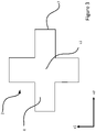
- Figure 3 illustrates the transformer arrangement from a side, cross-sectional view.
- Figure 4 schematically illustrates a vehicle 100 comprising an electrical power unit 110 and the transformer arrangement 1 according to the present disclosure, wherein the transformer arrangement 1 is mounted in said electrical power unit 110.
- the vehicle may be a ground-based vehicle, an air-borne vehicle , a ship or a UAV.
Landscapes
- Engineering & Computer Science (AREA)
- Power Engineering (AREA)
- Coils Of Transformers For General Uses (AREA)
Abstract
The present disclosure relates to a transformer arrangement (1) for mounting in an electrical power unit of a vehicle. The arrangement (1) comprising a transformer core (2) and a thermal shell (3) in contact with said transformer core (2). The transformer core (2) comprises a plurality of winding portions (4) extending from a common centre portion (c1) of said core (2), along a first axis (x1), a second axis (x2) and a third axis, (x3) each axis (x1, x2, x3) being orthogonal relative to each of the other axis (x1, x2, x3). Furthermore, each winding portion (4) comprises a conductive coil arrangement (5) wound around each winding portion (4).
Description
- The present disclosure relates to a transformer arrangement comprising a transformer core and a thermal shell in contact with said transformer core. Further, the disclosure relates to a vehicle comprising a transformer arrangement.
- For all electronic equipment size and weight are of utmost importance. In many electrical applications magnetic components are large, cumbersome and accounts for a great portion of the weight. This is especially true for electrical power units where both large filters and isolating transformers are magnetic components made out of iron of some sort. In e.g. the primary power unit (PPU) in an airborne vehicle, the weight of the transformers is many kilograms compared to the total weight of the PPU. Conventionally, it is not rare that the transformers approximately make up half of the total weight of the PPU. Further, transformers, and specifically transformers in vehicles tend to induce losses (e.g. hysteresis losses or eddy losses), which specifically for a moving object is a great drawback.
- Furthermore, transformers usually have poor thermal conductivity which is dependent on their thermal resistance. Accordingly, thermal resistance is proportional to the area of the transformer. In other words, to decrease the thermal resistance a larger area of the core is utilized in conventional transformer solutions - which in turn increases the weight of the transformer.
- Thus, the transformers in the market today, and specifically transformers mounted in vehicles, are heavy structures which usually have a high thermal resistance and additional drawbacks such as losses.
- Based on the above, there is room for transformers in the present art to explore the domain of providing an improved transformer arrangement compared to previous solutions. There is specifically a lack in the present art of how to improve a transformer arrangement to provide it with a reduced weight, decreased thermal resistance and with lower losses. Accordingly, there is room for improvements in the art to provide means for such transformer arrangements and vehicles containing such transformer arrangements.
- Even though some currently known solutions work well in some situations it would be desirable to provide a transformer arrangement and a vehicle comprising a transformer arrangement that fulfils requirements related to reducing weight, decreasing thermal resistance and lowering losses.
- It is therefore an object of the present disclosure to provide a transformer arrangement and a vehicle to mitigate, alleviate or eliminate one or more of the above-identified deficiencies and disadvantages.
- This object is achieved by means of a transformer arrangement as defined in the appended claims.
- The present disclosure is at least partly based on the insight that by providing an improved transformer arrangement and a vehicle having reduced weight and decreased thermal resistance and lowered loss the transformer arrangement will at least have an improved performance, be cheaper and more convenient to implement, operate and produce.
- In accordance with the disclosure there is provided a transformer arrangement according to
claim 1 and a vehicle according to claim 13. - The present disclosure provides a transformer arrangement for mounting in an electrical power unit of a vehicle comprising a transformer core and a thermal shell (i.e. thermally conductive shell) in contact with said transformer core. The transformer core comprises a plurality of winding portions extending from a common centre portion of said core, along a first axis, a second axis and a third axis, each axis being orthogonal relative to each of the other axis; wherein each winding portion comprises a conductive coil arrangement wound around each winding portion.
- A benefit of the transformer arrangement in accordance with the disclosure is that it provides for an arrangement that allows for the saturation of magnetic material in a plurality of dimensions and thus utilize a larger percent of the material in the transformer arrangement simultaneously. Consequently a significant weight reduction is achievable. However, a larger utilization of the material of the transformer may lead to higher effects which in turn increases the heat, however the transformer arrangement herein having a shell allows for excess heat to be lead away from said core.
- Further, by having the transformer shell in contact with the core, the shell provides for a return path for the magnetic flux along the periphery of the magnetic core. This may result in the benefit of achieving an improved (increased) inductance in the transformer arrangement. This also results in a surface that can be easily thermally managed, greatly improving and reducing the thermal resistance. It may be Further also allowing for maintaining a high power in the transformer arrangement as cooling is a vital part in transformer arrangements - bad cooling attributes results in that the transformer cannot be operated to a high power. Accordingly, the shell provides at least a magnetic return path and a cooling surface. Thus, the form and properties of the shell allows for that excess heat may be led away from the transformer core in a convenient manner.
- The thermal shell may be formed in a material being thermally conductive and magnetic. A benefit of this is that it allows for the material to lead magnetic flux as well as having the properties of being easily thermally managed.
- The thermal shell and the transformer core may be formed in the same material. Thus, allowing for a more convenient manufacturing procedure.
- The thermal shell of the transformer arrangement may be in contact with/connected to a cooling source arranged to cool said transformer core. In other words, the transformer arrangement may comprise a cooling source in contact with said thermal shell, i.e. an outer surface of said thermal shell. Thus, the thermal shell may be in-between said cooling source and said transformer core.
- The transformer arrangement may further comprises a rectification circuit for rectifying a current/voltage. The rectification circuit may be a 12-pulse rectifying circuit. Allowing for the transformer to convert current/voltage.
- The transformer core may be formed as an integral structure. Providing the benefit of an easy manufacturing process
- The transformer core may be in an isotropic magnetic material, preferably ferrite and the thermal shell may be formed in ferrite. This allows for a transformer arrangement having good magnetic properties as well as being easily thermally managed.
- The thermal shell may be in the form of a cube. The cube may have 6 flat surfaces, allowing the transformer arrangement to be thermally managed in an efficient manner. Thus, such a shape can easily be attached to e.g. a metal unit, cooling source or any other suitable thermally leading unit so to lead heat away from the transformer arrangement.
- There is further disclosed a vehicle comprising an electrical power unit and the transformer arrangement according to the disclosure herein, wherein the transformer arrangement is mounted in said electrical power unit. The vehicle may be a ground-vehicle, a ship or an airborne vehicle.
- In the following the disclosure will be described in a non-limiting way and in more detail with reference to exemplary embodiments illustrated in the enclosed drawings, in which:
- Figure 1
- illustrates an objective view transformer arrangement in accordance with an embodiment of the present disclosure;
- Figure 2A
- illustrates an objective view of a transformer core in accordance with an embodiment of the present disclosure;
- Figure 2B
- illustrates a side view of a transformer core in accordance with an embodiment of the present disclosure;
- Figure 3
- illustrates a cross-section of a side-view of a transformer core in accordance with an embodiment of the present disclosure; and
- Figure 4
- illustrates a vehicle comprising a transformer arrangement in accordance with an embodiment of the present disclosure.
- In the following detailed description, some embodiments of the present disclosure will be described. However, it is to be understood that features of the different embodiments are exchangeable between the embodiments and may be combined in different ways, unless anything else is specifically indicated. Even though in the following description, numerous specific details are set forth to provide a more thorough understanding of the provided transformer arrangement and vehicle, it will be apparent to one skilled in the art that the transformer arrangement and vehicle may be realized without these details. In other instances, well known constructions or functions are not described in detail, so as not to obscure the present disclosure.
-
Figure 1 illustrates an objective view of atransformer arrangement 1 in accordance with an embodiment of the present disclosure. Thetransformer arrangement 1 comprises atransformer core 2, and athermal shell 3 in contact with saidtransformer core 2. Thetransformer core 2 comprises a plurality of windingportions 4 extending from a common centre portion c1 of saidcore 2, along a first axis x1, a second axis x2 and a third axis x3, each axis x1, x2, x3 being orthogonal relative to each of the other axis x1, x2, x3, wherein each windingportion 4 comprises aconductive coil arrangement 5 wound around each windingportion 4. - As further shown in
Figure 1 , the first axis x1 is perpendicular to both the second axis x2 and the third axis x3, wherein the second axis x2 is perpendicular to the first axis x1 and the third axis x3, wherein the third axis x3 is perpendicular to the first and the second axis x1, x2. - Each winding
portion 4 of saidtransformer core 2 comprises, at adistal end 7, acontact surface 8, wherein saidthermal shell 3 is in contact with each of saidcontact surfaces 8 i.e. enclosing saidcore 2. In other words, Thus, allowing for a twofold gain, providing a return path of magnetic flux (reducing leakage flux) as well as providing a surface (i.e. the surfaces of the thermal shell 3) that can be easily thermally managed, greatly improving and reducing the thermal resistance when compared to conventional transformer arrangements. The thermal shell may be formed in a material being thermally conductive and magnetic. In some embodiments, the thermal shell and the transformer core are formed in the same material. - The material may be ferrite. Moreover, the
thermal shell 3 may be in the form of a cube as seen inFigure 1 , allowing it to be mobile and easily integrated in e.g. a power unit in a vehicle, further allowing it to be thermally managed easier. As further shown inFigure 1 , thethermal shell 3 may be in the form of a cube enclosing/surrounding said transformer core. In other words, anouter surface area 15 of saidthermal shell 3 may be greater/larger than an outer surface area 15' of saidtransformer core 2. - The
transformer core 2 may comprise magnetic material and as shown inFigure 1 , thetransformer core 2 is dimensioned orthogonally in three axis x1, x2, x3, allowing to utilize a larger percent of magnetic material simultaneously. For isotropic magnetic materials like ferrite, magnetic flux is a vector quantity (an example of practical use is 3D magnetometer). The saturation properties may occur in the same manner. The present disclosure may allow flow of three times as much magnetic flux in the same material without saturation. Further, the present disclosure provides for weight reduction. Thetransformer core 2 may be formed as an integral structure. Thetransformer core 2 may be in an isotropic magnetic material, preferably ferrite. Thethermal shell 3 shown inFigure 1 may have any suitable thickness. - As shown in
Figure 2A , the transformer core comprises a first 9, a second 10 and athird pair 11 of windingportions 4, wherein eachpair portions 4 extend opposite to each other along a corresponding axis x1, x2, x3. In other words, each pair of windingportions 4 extend along the same axis x1, x2, x3 in opposing directions. In other words, each pair of windingportions 4 extend away from the other along a common axis x1, x2, x3. -
Figures 1 and2A illustrate that thecore 2 comprise aconductive coil arrangement 5, theconductive coil arrangement 5 may be a primary conductive coil arrangement connected to an input drawing power from a source and a secondary conductive coil arrangement connected to an output supplying energy to a load, wherein each pair of winding portions comprises a primary coil arrangement and a secondary coil arrangement dividedly wound around the pair of winding portions. Thus, thetransformer arrangement 1 comprises threepairs portions 4, wherein eachpair Figure 2A , eachpair portion 9', 9", 10', 10", 11', 11". - Thus, a primary coil arrangement of one axis (i.e. for one
pair first pair 10, consequently, the same primary coil arrangement is divided to befurther wound 5 turns around a second windingportion 10" in thefirst pair 10. Moreover, each secondary coil arrangement may in the same manner be dividedly wound 5 turns around each windingportion 10', 10" in thepair 10. This may apply to each of thepairs pair 9", 10", 11" (i.e. forming three transformers, each for each pair along each axis). - The primary/secondary coil arrangement may each be dividedly wound so that there is a distance of one radius between the divided coil arrangements located on each
pair 10. - The
transformer arrangement 1 may further comprise a rectification circuit for rectifying a current/voltage. The rectification circuit may be a 12-pulse rectifying circuit (not shown). -
Figure 2B illustrates thetransformer arrangement 1 from a side view, as seen inFigure 2B , each of the windingportions 4 are perpendicular to each of the other windingportions 4. - Further, it is shown in
Figure 2B that the centre portion c1 is in the center of thetransformer arrangement 1 and each windingportion 4 extend away from the centre portion c1. This is also seen inFigure 3 in more detail, showing that the centre portion c1 is center of thecore 2. -
Figure 3 illustrates the transformer arrangement from a side, cross-sectional view. -
Figure 4 schematically illustrates avehicle 100 comprising anelectrical power unit 110 and thetransformer arrangement 1 according to the present disclosure, wherein thetransformer arrangement 1 is mounted in saidelectrical power unit 110. - The vehicle may be a ground-based vehicle, an air-borne vehicle , a ship or a UAV.
Claims (13)
- A transformer arrangement (1) for mounting in an electrical power unit of a vehicle comprising:- a transformer core (2);- a thermal shell (3) in contact with said transformer core (2);wherein said transformer core (2) comprises a plurality of winding portions (4) extending from a common centre portion (c1) of said core (2), along a first axis (x1), a second axis (x2) and a third axis, (x3) each axis (x1, x2, x3) being orthogonal relative to each of the other axis (x1, x2, x3); wherein each winding portion (4) comprises a conductive coil arrangement (5) wound around each winding portion (4).
- The transformer arrangement (1) according to claim 1, each winding portion of said transformer core (2) comprises, at a distal end (7), a contact surface (8), wherein said thermal shell (3) is in contact with each of said contact surfaces (8).
- The transformer arrangement (1) according to any one of the claims 1 or 2, wherein the transformer core (2) comprises a first (9), a second (10) and a third pair (11) of winding portions, wherein each pair (9, 10, 11) of winding portions extend along a common axis (x1, x2, x3) away from the centre portion (c1).
- The transformer arrangement (1) according to any one of the claims 1-3, wherein the conductive coil arrangement (5) is a primary conductive coil arrangement connected to an input drawing power from a source and a secondary conductive coil arrangement connected to an output supplying energy to a load, wherein each pair of winding portions (9, 10, 11) comprises a primary coil arrangement and a secondary coil arrangement dividedly wound around the pair of winding portions (9, 10, 11) respectively.
- The transformer arrangement (1) according to any one of the claims 1-4, wherein the thermal shell (3) is formed in a material being thermally conductive and magnetic.
- The transformer arrangement (1) according to any one of the claims 1-5, wherein the thermal shell (3) and the transformer core (2) are formed in the same material.
- The transformer arrangement (1) according to any one of the claims 1-6, wherein said transformer arrangement (1) further comprises a rectification circuit for rectifying a current/voltage.
- The transformer arrangement (1) according to any one of the claims 1-7, wherein the rectification circuit is a 12-pulse rectifying circuit.
- The transformer arrangement (1) according to any one of the claims 1-8, wherein the transformer core (2) is formed as an integral structure.
- The transformer arrangement (1) according to any one of the claims 1-9, wherein said transformer core (2) is in an isotropic magnetic material, preferably ferrite.
- The transformer arrangement (1) according to any one of the claims 1-10, wherein said thermal shell (3) is in the form of a cube.
- The transformer arrangement (1) according to any one of the claims 1-11, wherein the thermal shell (3) is formed in ferrite.
- A vehicle (100) comprising;a electrical power unit (110); andthe transformer arrangement (1) according to any one of the preceding claims,wherein the transformer arrangement (1) is mounted in said electrical power unit.
Applications Claiming Priority (1)
| Application Number | Priority Date | Filing Date | Title |
|---|---|---|---|
| SE2100103A SE545081C2 (en) | 2021-06-18 | 2021-06-18 | A weight reducing transformer arrangement comprising a shell and a core with three orthogonal axes |
Publications (1)
| Publication Number | Publication Date |
|---|---|
| EP4113547A1 true EP4113547A1 (en) | 2023-01-04 |
Family
ID=82058467
Family Applications (1)
| Application Number | Title | Priority Date | Filing Date |
|---|---|---|---|
| EP22178994.4A Withdrawn EP4113547A1 (en) | 2021-06-18 | 2022-06-14 | A transformer arrangement |
Country Status (3)
| Country | Link |
|---|---|
| US (1) | US20220406509A1 (en) |
| EP (1) | EP4113547A1 (en) |
| SE (1) | SE545081C2 (en) |
Citations (5)
| Publication number | Priority date | Publication date | Assignee | Title |
|---|---|---|---|---|
| US4210859A (en) * | 1978-04-18 | 1980-07-01 | Technion Research & Development Foundation Ltd. | Inductive device having orthogonal windings |
| FR2621415A1 (en) * | 1987-10-01 | 1989-04-07 | Equip Electr Moteur | Magnetic circuit of electrical transformer, especially of closed-circuit ignition coil, for motor vehicle internal combustion engine |
| EP0551555A1 (en) * | 1992-01-17 | 1993-07-21 | Mitsubishi Denki Kabushiki Kaisha | Transformer for mouting in a vehicle |
| WO2001075911A1 (en) * | 2000-04-03 | 2001-10-11 | Abb Ab | A multiphase induction device |
| US20030062980A1 (en) * | 2000-03-09 | 2003-04-03 | Guntram Scheible | Configuration for producing electrical power from a magnetic field |
Family Cites Families (7)
| Publication number | Priority date | Publication date | Assignee | Title |
|---|---|---|---|---|
| GB191325695A (en) * | 1913-11-10 | 1914-10-15 | Karl Martin Faye-Hansen | Improvements in Reactance or Choking Coils. |
| US3067374A (en) * | 1960-01-05 | 1962-12-04 | High Voltage Engineering Corp | Multi-phase transformer |
| US4656450A (en) * | 1986-05-12 | 1987-04-07 | Northern Telecom Limited | Transformer and ferrite core structure therefor |
| DE3743500C2 (en) * | 1987-12-22 | 1996-07-18 | Morgenstern Juergen | Electromagnetic device for position measurements |
| US5177460A (en) * | 1990-01-04 | 1993-01-05 | Dhyanchand P John | Summing transformer for star-delta inverter having a single secondary winding for each group of primary windings |
| NZ589312A (en) * | 2010-11-16 | 2013-03-28 | Powerbyproxi Ltd | Battery having inductive power pickup coils disposed within the battery casing and at an angle to the casing axis |
| DE112012003217T5 (en) * | 2011-08-01 | 2014-07-03 | Autonetworks Technologies, Ltd | inductor |
-
2021
- 2021-06-18 SE SE2100103A patent/SE545081C2/en unknown
-
2022
- 2022-06-14 EP EP22178994.4A patent/EP4113547A1/en not_active Withdrawn
- 2022-06-16 US US17/807,286 patent/US20220406509A1/en active Pending
Patent Citations (5)
| Publication number | Priority date | Publication date | Assignee | Title |
|---|---|---|---|---|
| US4210859A (en) * | 1978-04-18 | 1980-07-01 | Technion Research & Development Foundation Ltd. | Inductive device having orthogonal windings |
| FR2621415A1 (en) * | 1987-10-01 | 1989-04-07 | Equip Electr Moteur | Magnetic circuit of electrical transformer, especially of closed-circuit ignition coil, for motor vehicle internal combustion engine |
| EP0551555A1 (en) * | 1992-01-17 | 1993-07-21 | Mitsubishi Denki Kabushiki Kaisha | Transformer for mouting in a vehicle |
| US20030062980A1 (en) * | 2000-03-09 | 2003-04-03 | Guntram Scheible | Configuration for producing electrical power from a magnetic field |
| WO2001075911A1 (en) * | 2000-04-03 | 2001-10-11 | Abb Ab | A multiphase induction device |
Also Published As
| Publication number | Publication date |
|---|---|
| SE545081C2 (en) | 2023-03-21 |
| SE2100103A1 (en) | 2022-12-19 |
| US20220406509A1 (en) | 2022-12-22 |
Similar Documents
| Publication | Publication Date | Title |
|---|---|---|
| US7026905B2 (en) | Magnetically controlled inductive device | |
| KR102086355B1 (en) | Linear electromagnetic device | |
| US6879237B1 (en) | Power transformers and power inductors for low-frequency applications using isotropic material with high power-to-weight ratio | |
| US9412510B2 (en) | Three-phase reactor | |
| SG11202108170UA (en) | Wireless power transfer based on magnetic induction | |
| US9633776B2 (en) | Variable core electromagnetic device | |
| US10224141B2 (en) | Coupled inductor | |
| CN102971813B (en) | Reactor | |
| WO2018201484A1 (en) | Transformer, and switching power supply | |
| EP4287221A1 (en) | Heat transfer from transformer windings | |
| JP6490355B2 (en) | Reactor parts and reactors | |
| US20220406509A1 (en) | Transformer arrangement | |
| CN207425599U (en) | A kind of hyperfrequency secondary resonance transformer | |
| CN214377944U (en) | Differential-common mode inductor | |
| CA2332363C (en) | Inductance arrangement | |
| CN216599414U (en) | Power module and power supply device | |
| KR102555275B1 (en) | iron core structure of transformer | |
| US20250014801A1 (en) | Planar transformer | |
| US20250037913A1 (en) | Assembled inductor | |
| US20250378984A1 (en) | Magnetic Integrated Inductor and Assembly Thereof | |
| CN213635671U (en) | Transformer for motor vehicle power supply | |
| CN206574579U (en) | Flat surface transformer | |
| TWM668868U (en) | Transformer module | |
| CN119542010A (en) | Stacked coil transformer structure | |
| CN223808990U (en) | High-performance magnetic core and inductor |
Legal Events
| Date | Code | Title | Description |
|---|---|---|---|
| PUAI | Public reference made under article 153(3) epc to a published international application that has entered the european phase |
Free format text: ORIGINAL CODE: 0009012 |
|
| STAA | Information on the status of an ep patent application or granted ep patent |
Free format text: STATUS: THE APPLICATION HAS BEEN PUBLISHED |
|
| AK | Designated contracting states |
Kind code of ref document: A1 Designated state(s): AL AT BE BG CH CY CZ DE DK EE ES FI FR GB GR HR HU IE IS IT LI LT LU LV MC MK MT NL NO PL PT RO RS SE SI SK SM TR |
|
| STAA | Information on the status of an ep patent application or granted ep patent |
Free format text: STATUS: THE APPLICATION IS DEEMED TO BE WITHDRAWN |
|
| 18D | Application deemed to be withdrawn |
Effective date: 20230705 |