EP4113359B1 - Verfahren zur herstellung von schlauch- und rohrleitungen mit rfid-chips - Google Patents
Verfahren zur herstellung von schlauch- und rohrleitungen mit rfid-chips Download PDFInfo
- Publication number
- EP4113359B1 EP4113359B1 EP22178281.6A EP22178281A EP4113359B1 EP 4113359 B1 EP4113359 B1 EP 4113359B1 EP 22178281 A EP22178281 A EP 22178281A EP 4113359 B1 EP4113359 B1 EP 4113359B1
- Authority
- EP
- European Patent Office
- Prior art keywords
- electrically conductive
- rfid chips
- hoseline
- conductive structures
- pipeline
- Prior art date
- Legal status (The legal status is an assumption and is not a legal conclusion. Google has not performed a legal analysis and makes no representation as to the accuracy of the status listed.)
- Active
Links
Images
Classifications
-
- G—PHYSICS
- G06—COMPUTING OR CALCULATING; COUNTING
- G06K—GRAPHICAL DATA READING; PRESENTATION OF DATA; RECORD CARRIERS; HANDLING RECORD CARRIERS
- G06K1/00—Methods or arrangements for marking the record carrier in digital fashion
- G06K1/12—Methods or arrangements for marking the record carrier in digital fashion otherwise than by punching
-
- F—MECHANICAL ENGINEERING; LIGHTING; HEATING; WEAPONS; BLASTING
- F16—ENGINEERING ELEMENTS AND UNITS; GENERAL MEASURES FOR PRODUCING AND MAINTAINING EFFECTIVE FUNCTIONING OF MACHINES OR INSTALLATIONS; THERMAL INSULATION IN GENERAL
- F16L—PIPES; JOINTS OR FITTINGS FOR PIPES; SUPPORTS FOR PIPES, CABLES OR PROTECTIVE TUBING; MEANS FOR THERMAL INSULATION IN GENERAL
- F16L11/00—Hoses, i.e. flexible pipes
- F16L11/04—Hoses, i.e. flexible pipes made of rubber or flexible plastics
- F16L11/12—Hoses, i.e. flexible pipes made of rubber or flexible plastics with arrangements for particular purposes, e.g. specially profiled, with protecting layer, heated, electrically conducting
-
- G—PHYSICS
- G06—COMPUTING OR CALCULATING; COUNTING
- G06K—GRAPHICAL DATA READING; PRESENTATION OF DATA; RECORD CARRIERS; HANDLING RECORD CARRIERS
- G06K19/00—Record carriers for use with machines and with at least a part designed to carry digital markings
- G06K19/06—Record carriers for use with machines and with at least a part designed to carry digital markings characterised by the kind of the digital marking, e.g. shape, nature, code
- G06K19/067—Record carriers with conductive marks, printed circuits or semiconductor circuit elements, e.g. credit or identity cards also with resonating or responding marks without active components
- G06K19/07—Record carriers with conductive marks, printed circuits or semiconductor circuit elements, e.g. credit or identity cards also with resonating or responding marks without active components with integrated circuit chips
- G06K19/077—Constructional details, e.g. mounting of circuits in the carrier
- G06K19/07749—Constructional details, e.g. mounting of circuits in the carrier the record carrier being capable of non-contact communication, e.g. constructional details of the antenna of a non-contact smart card
- G06K19/07758—Constructional details, e.g. mounting of circuits in the carrier the record carrier being capable of non-contact communication, e.g. constructional details of the antenna of a non-contact smart card arrangements for adhering the record carrier to further objects or living beings, functioning as an identification tag
-
- F—MECHANICAL ENGINEERING; LIGHTING; HEATING; WEAPONS; BLASTING
- F16—ENGINEERING ELEMENTS AND UNITS; GENERAL MEASURES FOR PRODUCING AND MAINTAINING EFFECTIVE FUNCTIONING OF MACHINES OR INSTALLATIONS; THERMAL INSULATION IN GENERAL
- F16L—PIPES; JOINTS OR FITTINGS FOR PIPES; SUPPORTS FOR PIPES, CABLES OR PROTECTIVE TUBING; MEANS FOR THERMAL INSULATION IN GENERAL
- F16L2201/00—Special arrangements for pipe couplings
- F16L2201/60—Identification or marking
-
- G—PHYSICS
- G06—COMPUTING OR CALCULATING; COUNTING
- G06K—GRAPHICAL DATA READING; PRESENTATION OF DATA; RECORD CARRIERS; HANDLING RECORD CARRIERS
- G06K19/00—Record carriers for use with machines and with at least a part designed to carry digital markings
- G06K19/06—Record carriers for use with machines and with at least a part designed to carry digital markings characterised by the kind of the digital marking, e.g. shape, nature, code
- G06K19/067—Record carriers with conductive marks, printed circuits or semiconductor circuit elements, e.g. credit or identity cards also with resonating or responding marks without active components
- G06K19/07—Record carriers with conductive marks, printed circuits or semiconductor circuit elements, e.g. credit or identity cards also with resonating or responding marks without active components with integrated circuit chips
- G06K19/077—Constructional details, e.g. mounting of circuits in the carrier
- G06K19/07749—Constructional details, e.g. mounting of circuits in the carrier the record carrier being capable of non-contact communication, e.g. constructional details of the antenna of a non-contact smart card
- G06K19/07758—Constructional details, e.g. mounting of circuits in the carrier the record carrier being capable of non-contact communication, e.g. constructional details of the antenna of a non-contact smart card arrangements for adhering the record carrier to further objects or living beings, functioning as an identification tag
- G06K19/07764—Constructional details, e.g. mounting of circuits in the carrier the record carrier being capable of non-contact communication, e.g. constructional details of the antenna of a non-contact smart card arrangements for adhering the record carrier to further objects or living beings, functioning as an identification tag the adhering arrangement making the record carrier attachable to a tyre
Definitions
- the invention relates to a method for producing hose and pipe sections with RFID chips.
- Hoses and pipes are sometimes exposed to unfavorable environmental and operating conditions, which means that hoses and pipes, especially safety-relevant lines, must be continuously monitored. If this is not possible, it is common practice to set replacement intervals as part of preventive maintenance.
- RFID chips have been established in the past for both identification and signal transmission from sensors, and are also used in the field of hose and pipe technology.
- RFID chips with antennas on a carrier material in the form of labels or strips are common. These can be subsequently attached to the outside of the hose. It is also known as state of the art that the RFID chips are wound or spiraled around a plastic pipe on a carrier material in the form of strips with regular spacing between them and a defined pitch. US 903 8670 B2 reveals such a solution.
- the widely used RFID chips on carrier material in the form of labels or strips are not suitable for insertion into the hose during the hose manufacturing process.
- the shape, format and design have a negative impact on product performance, such as delamination of the layers, which can ultimately lead to the hose failing.
- Such a thread structure can be embedded much better in an elastomer layer of a hose than in a band-shaped structure.
- the spiral winding of the RFID threads mentioned above requires a corresponding winding device, which is often used in hose and pipe production for the various reinforcement layers in the pipes and is therefore not available for further winding processes.
- the winding process especially for pipes with larger diameters, involves a high consumption of RFID threads.
- This process requires a transfer film onto which the RFID structure with antennas is applied, which must then be transferred to the object to be marked.
- the invention is based on the object of developing the known methods for embedding RFID chips in hoses and pipes in such a way that embedding is possible without significantly influencing the mechanical properties of the product and with little effort.
- This object is achieved by applying conductive structures of predetermined geometry to the outer surface of a hose or pipe blank at predetermined axial intervals, and an RFID chip is placed on each of these conductive structures, whereby the RFID chips come into electrically conductive connection with the respective conductive structure and the hose or pipe blank is vulcanized or cured together with the conductive structures and the attached RFID chips and then divided into sections of predetermined length.
- This process has the advantage that no specially prepared thread material needs to be provided.
- the process is also very flexible, as the distance between the RFID chips on the conductive structures acting as antennas can be easily adapted to the respective designs of the hose or pipe blanks.
- the conductive structures are printed with an electrically conductive ink.
- This process enables continuous production of the blanks, with electrically conductive inks being particularly suitable for printing.
- the areas intended for dividing the finished vulcanized hose or pipe are formed by the Detecting the position of the RFID chips on the hose or pipe and at predetermined intervals from the position of the respective RFID chips.
- the hose or pipe blank is made of an elastomeric raw material.
- Elastomer raw materials can be vulcanized to form very resistant hoses or pipes, whereby a wear-resistant connection between the elastomer raw materials and the electrically conductive structures is achieved.
- the elastomeric hose or pipe blank is made of TPE material and, in finished form, is a protective hose against abrasion damage to a hose or pipe.
- a protective hose made of TPE material improves the abrasion resistance of the hose or pipe.
- the electrically conductive structures including the applied RFID chips are equipped with a protective coating against external influences.
- Such a protective coating improves the resistance to abrasion of the applied structures.
- the invention further relates to a device for carrying out the method according to the invention.
- This arrangement allows a very flexible design of the method according to the invention.
- the device for applying linear electrically conductive structures is an inkjet print head.
- An inkjet print head can be programmed using simple means and allows continuous as well as discontinuous application of the electrically conductive structures.
- the device further comprises a device for detecting the position of RFID chips on the finished hose or pipe, a feed device and a cutting device.
- Such an arrangement makes it possible to cut the finished hose or pipe depending on the position of the RFID chips, so that it is ensured that after cutting each hose or pipe section has exactly one RFID chip.
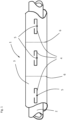
- FIG. 1 is a possible result of the method according to the invention in a Schematic diagram shown.
- a hose line 1 has an inner base hose 2 made of elastomeric material.
- a TPE protective hose 3 is arranged around the base hose 2 and is extruded around the base hose 2.
- electrically conductive structures 4 are printed onto the surface of the TPE protective tube 3 at predetermined, not necessarily equal intervals, using conductive inks.
- the electrically conductive structures 4 have a shape roughly like a large "C”.
- RFID chips 5 are placed on these electrically conductive structures 4 in such a way that they are in electrical contact with the respective electrically conductive structure.
- both the electrically conductive structures 4 and the RFID chips 5 are firmly connected to the elastomeric material of the protective tube 3.
- the respective electrically conductive structure 4 then serves as an antenna for the RFID chips 5.
- the RFID chips 5 serve as a marking, so that a corresponding division device (not shown here) can divide the hose or pipe 1 into individual sections at the points 6 triggered by the RFID chips 5 and arranged at predetermined distances from the RFID chips 5, thereby ensuring that each section has exactly one RFID chip 5 and that no RFID chip 5 is destroyed during division.
Landscapes
- Engineering & Computer Science (AREA)
- Physics & Mathematics (AREA)
- General Physics & Mathematics (AREA)
- Theoretical Computer Science (AREA)
- General Engineering & Computer Science (AREA)
- Computer Hardware Design (AREA)
- Microelectronics & Electronic Packaging (AREA)
- Mechanical Engineering (AREA)
- Lining Or Joining Of Plastics Or The Like (AREA)
- Rigid Pipes And Flexible Pipes (AREA)
Description
- Die Erfindung betrifft ein Verfahren zur Herstellung von Schlauch- und Rohrleitungsabschnitten mit RFID-Chips.
- Schlauch- und Rohrleitungen sind teilweise ungünstigen Umwelt- und Betriebsbedingungen ausgesetzt, was insbesondere bei sicherheitsrelevanten Leitungen zur Folge hat, dass die Schlauch- und Rohrleitungen kontinuierlich überwacht werden müssen. Ist dies gegebenenfalls nicht möglich, ist es üblich, im Rahmen der vorbeugenden Instandhaltung Wechselintervalle festzulegen.
- In beiden Fällen ist es notwendig, die Schlauch- und Rohrleitungen mindestens zu identifizieren und/oder aber mit einer kontinuierlich arbeitenden Sensorik auszustatten. Sowohl für die Identifikation als auch für die Signalübertragung von Sensoren haben sich in der Vergangenheit RFID-Chips etabliert, die auch im Bereich der Schlauch- und Rohrleitungstechnik zum Einsatz kommen.
- Üblich sind RFID-Chips mit Antennen auf einem Trägermaterial in Form von Etiketten oder Streifen. Diese können nachträglich an der Schlauchaußenseite befestigt werden. Weiterhin ist es als Stand der Technik bekannt, dass die RFID-Chips auf Trägermaterial in Streifenform mit regelmäßigem Abstand zueinander und definierter Steigung um ein Kunststoffrohr gewunden bzw. spiralförmig aufgebracht werden. Die
US 903 8670 B2 - Die nachträgliche Montage der RFID-Chips an der Schlauchaußenseite führt zu zusätzlichem Aufwand. Weitere Nachteile sind die Gefahr von Verlust oder Beschädigungen, fehlende Redundanz, die Verletzungsgefahr sowie die Ablagerungsmöglichkeiten von Verunreinigungen.
- Die weitverbreiteten RFID-Chips auf Trägermaterial in Form von Etiketten oder Streifen eignen sich nicht zur Einbringung in den Schlauch während des Schlauchherstellungs-prozesses. Durch Form, Format und bauartbedingt ergeben sich negative Auswirkungen auf die Produktperformance wie beispielsweise Delamination der Schichten, die letztlich zum Ausfall des Schlauches führen können.
- In der
US 2019/0 27 69 82 A1 ist eine Lösung vorgeschlagen, bei der ein Seil mit einem RFID-Faden ausgestattet ist, wobei der RFID-Faden eine fadenartige Trägerstruktur aufweist, auf der in vorbestimmten Abständen RFID-Chips angeordnet sind. - Eine derartige Fadenstruktur lässt sich statt einer bandförmigen Struktur deutlich besser in eine Elastomer Schicht eines Schlauches einbetten. Das oben erwähnte spiralförmige Aufwickeln der RFID-Fäden erfordert aber eine entsprechende Wickelvorrichtung, die bei der Schlauch- und Rohrleitungsproduktion oftmals für die verschiedenen Verstärkungslagen in den Leitungen genutzt wird und daher nicht für weitere Wickelvorgänge zur Verfügung steht. Außerdem ist mit dem Aufwickeln, insbesondere bei Leitungen mit größeren Durchmessern, ein hoher Verbrauch an RFID-Fäden verbunden.
- In der
DE 10 2006 061 798 A1 ist ein Verfahren zur Anbringung von Kennzeichen auf Substratoberflächen mit Hilfe eines Transferverfahrens offenbart, bei dem unmittelbar von einer präparierten oder vorgedruckten Release-Trägerfolie eine auf der Release-Trägerfolie
befindliche Transferschicht auf die Substratoberfläche übertragen wird und dort ein nur unter Zerstörung entfernbares Haftbild entstehen lässt. - Bei diesem Verfahren ist eine Transferfolie erforderlich, auf die die RFID-Struktur mit Antennen aufgebracht wird, die dann auf den zu kennzeichnenden Gegenstand übertragen werden muss.
- Abgesehen davon, dass das Verfahren die Transferfolie als zusätzliches Bauteil benötigt, ist es auch mit zusätzlichen Arbeitsschritten verbunden und bedarf einer entsprechenden Vorbereitung.
- Der Erfindung liegt die Aufgabe zugrunde, die bekannten Verfahren zur Einbettung von RFID-Chips in Schlauch- und Rohrleitungen so weiterzubilden, dass die Einbettung ohne nennenswerte Beeinflussung der mechanischen Eigenschaften des Produkts und mit geringem Aufwand möglich ist.
- Diese Aufgabe wird dadurch gelöst, dass auf die äußere Oberfläche eines Schlauch- oder Rohrleitungsrohlings in vorbestimmten axialen Abständen leitfähige Strukturen vorbestimmter Geometrie auf den Schlauch- oder Rohrleitungsrohling aufgebracht werden, und auf diese leitfähigen Strukturen jeweils ein RFID-Chip aufgesetzt wird, wobei die RFID-Chips mit der jeweiligen leitfähigen Struktur in elektrisch leitende Verbindung zu stehen kommen und der Schlauch- oder Rohrleitungsrohling mit den leitfähigen Strukturen und den aufgesetzten RFID-Chips zusammenvulkanisiert oder ausgehärtet und anschließend in Abschnitte vorbestimmter Länge zerteilt wird.
- Dieses Verfahren hat den Vorteil, dass kein speziell ausgerüstetes Fadenmaterial bereitgestellt werden muss. Außerdem ist das Verfahren sehr flexibel, da der Abstand der RFID-Chips auf den als Antennen fungierenden leitfähigen Strukturen sehr einfach an die jeweiligen Ausführungsformen der Schlauch- oder Rohrleitungsrohlinge anpassbar ist.
- In einer Weiterbildung der Erfindung sind die leitfähigen Strukturen mit einer elektrisch leitfähigen Tinte aufgedruckt.
- Diese Verfahren ermöglicht eine kontinuierliche Fertigung der Rohlinge, wobei elektrisch leitfähige Tinten besonders gut zum Drucken geeignet sind.
- In einer Weiterbildung der Erfindung werden die zur Zerteilung der fertig vulkanisierten Schlauch- oder Rohrleitung vorgesehenen Stellen durch die Erfassung der Lage der RFID-Chips auf der Schlauch- oder Rohrleitung und in vorbestimmten Abständen von der Lage der jeweiligen RFID-Chips bestimmt.
- Dies hat den Vorteil, dass auf einfache Weise realisierbar ist, dass ein Schlauch- oder Rohrleitungsabschnitt immer genau einen RFID-Chip aufweist.
- In einer Weiterbildung der Erfindung ist der Schlauch- oder Rohrleitungsrohling aus einem elastomeren Rohmaterial ausgebildet.
- Elastomeren Rohmaterialien lassen sich zu sehr widerstandsfähigen Schlauch- oder Rohrleitungen vulkanisieren, wobei eine verschleißfeste Verbindung der elastomeren Rohmaterialien mit den elektrisch leitfähigen Strukturen erreicht wird..
- In einer Weiterbildung der Erfindung ist der elastomere Schlauch- oder Rohrleitungsrohling aus TPE-Material ausgebildet und ist in fertiger Form ein Schutzschlauch gegen Scheuerschäden einer Schlauch- oder Rohrleitung.
- Ein Schutzschlauch aus TPE Material verbessert die Abriebfestigkeit der Schlauch- oder Rohrleitung.
- In einer Weiterbildung der Erfindung werden die elektrisch leitfähigen Strukturen einschließlich der aufgebrachten RFID-Chips mit einem Schutzüberzug gegen äußere Einflüsse ausgerüstet.
- Ein solcher Schutzüberzug verbessert die Widerstandsfähigkeit gegen Abrieb der aufgebrachten Strukturen.
- Die Erfindung betrifft weiter eine Vorrichtung zur Durchführung des erfindungsgemäßen Verfahrens.
- Diese Vorrichtung ist dadurch gekennzeichnet, dass sie mindestens folgende Teile aufweist, nämlich
- eine Einrichtung zur Aufbringung von elektrisch leitfähigen Strukturen vorbestimmter Geometrie auf die äußere Oberfläche eines Schlauch- oder Rohrleitungsrohlings in vorbestimmten Abständen,
- eine Einrichtung zum Aufsetzen von RFID-Chips auf die elektrisch leitfähigen Strukturen, wobei die RFID-Chips mit der jeweiligen elektrisch leitfähigen Struktur in elektrisch leitende Verbindung zu stehen kommen und den Schlauch- oder Rohrleitungsrohling,
- eine Vulkanisations- oder aus Aushärteeinrichtung, in der der Schlauch- oder Rohrleitungsrohling mit den aufgebrachten elektrisch leitfähigen Strukturen und den aufgesetzten RFID-Chips zusammenvulkanisiert oder ausgehärtet wird.
- Diese Anordnung erlaubt eine sehr flexible Gestaltung des erfindungsgemäßen Verfahrens.
- In einer Weiterbildung der Erfindung ist die Einrichtung zur Aufbringung von linienförmigen elektrisch leitfähigen Strukturen ein Tintenstrahl-Druckkopf.
- Ein Tintenstrahl-Druckkopf ist mit einfachen Mitteln programmierbar und erlaubt eine kontinuierliche, aber auch eine diskontinuierliche Aufbringung der elektrisch leitfähigen Strukturen.
- In einer Weiterbildung der Erfindung weist die Vorrichtung weiter eine Einrichtung zur Erfassung der Lage von RFID-Chips auf der fertigen Schlauch- oder Rohrleitung, eine Vorschubeinrichtung und eine Zerteileinrichtung auf.
- Eine derartige Anordnung ermöglicht, das Zerteilen der fertigen Schlauch- oder Rohrleitung in Abhängigkeit von der Lage der RFID-Chips zu realisieren, sodass sichergestellt ist, dass nach dem zerteilen jeder Schlauch- oder Rohrleitungsabschnitt genau einen RFID Chip aufweist.
- Anhand der Zeichnung wird nachstehend ein Beispiel der Erfindung näher erläutert. In der
Fig. 1 ist ein mögliches Ergebnis des erfindungsgemäßen Verfahrens in einer Prinzipskizze gezeigt. Eine Schlauchleitung 1 weist einen inneren Grundschlauch 2 aus elastomerem Material auf. Um den Grundschlauch 2 herum ist ein TPE-Schutzschlauch 3 angeordnet, der um den Grundschlauch 2 herum extrudiert ist. - Nach der Extrusion des TPE-Schutzschlauchs 3 werden in vorbestimmten, nicht zwingend gleichen Abständen elektrisch leitfähige Strukturen 4 auf die Oberfläche des TPE-Schutzschlauchs 3 aufgedruckt, wobei leitfähige Tinten zum Einsatz kommen. Im vorliegenden Beispiel weisen die elektrisch leitfähigen Strukturen 4 eine Form in etwa eines großen "C" auf. Auf diese elektrisch leitfähigen Strukturen 4 werden RFID-Chips 5 so aufgesetzt, dass sie mit der jeweiligen elektrisch leitfähigen Struktur in elektrischem Kontakt stehen.
- Bei einer anschließenden Vulkanisation bzw. Aushärtung des Schutzschlauches 3 werden sowohl die elektrisch leitfähigen Strukturen 4 als auch die RFID-Chips 5 mit dem elastomeren Material des Schutzschlauches 3 fest verbunden. Die jeweilige elektrisch leitfähige Struktur 4 dient dann als Antenne für die RFID-Chips 5.
- Bei der nachfolgenden Zerteilung der fertigen Schlauch- oder Rohrleitung 1 dienen die RFID-Chips 5 als Markierung, sodass eine entsprechende, hier nicht gezeigte Zerteileinrichtung an den von den RFID-Chips 5 getriggerten und in vorbestimmten Abständen von den RFID-Chips 5 angeordneten Stellen 6 die Schlauch- oder Rohrleitung 1 in einzelne Abschnitte zerteilt werden kann, wodurch sichergestellt ist, dass jeder Abschnitt genau einen RFID-Chip 5 aufweist und kein RFID-Chip 5 bei der Zerteilung zerstört wird.
-
- 1
- Schlauch- oder Rohrleitungsrohling
- 2
- Grundschlauch des Schlauch- oder Rohrleitungsrohlings 1
- 3
- TPE-Schutzschlauch
- 4
- elektrisch leitfähige Strukturen
- 5
- RFID-Chips
- 6
- vorbestimmte Stellen zum Zerteilen der fertigen Schlauch- oder Rohrleitung
Claims (9)
- Verfahren zur Herstellung von Schlauch- und Rohrleitungen (1) mit RFID-Chips (5), dadurch gekennzeichnet, dass auf die äußere Oberfläche eines Schlauch- oder Rohrleitungsrohlings (1) in vorbestimmten axialen Abständen elektrisch leitfähige Strukturen (4) vorbestimmter Geometrie aufgebracht werden, und auf diese elektrisch leitfähigen Strukturen (4) jeweils ein RFID-Chip (5) aufgesetzt wird, wobei die RFID-Chips (5) mit der jeweiligen elektrisch leitfähigen Struktur (4) in elektrisch leitende Verbindung zu stehen kommen und der Schlauch- oder Rohrleitungsrohling (1) mit den aufgebrachten elektrisch leitfähigen Strukturen (4) und den aufgesetzten RFID-Chips (5) zusammenvulkanisiert oder ausgehärtet und anschließend in Abschnitte vorbestimmter Länge zerteilt wird.
- Verfahren nach Anspruch 1, dadurch gekennzeichnet, dass die elektrisch leitfähigen Strukturen (4) mit einer elektrisch leitfähigen Tinte aufgedruckt sind.
- Verfahren nach Anspruch 1 oder 2, dadurch gekennzeichnet, dass die zur Zerteilung der fertig vulkanisierten Schlauch- oder Rohrleitung vorgesehenen Stellen (6) durch die Erfassung der Lage der RFID-Chips (5) auf der fertigen Schlauch- oder Rohrleitung und in vorbestimmten Abständen von der Lage der jeweiligen RFID-Chips (5) bestimmt werden.
- Verfahren nach Anspruch 1, 2 oder 3, dadurch gekennzeichnet, dass der Schlauch- oder Rohrleitungsrohling (1) aus einem elastomeren Rohmaterial ausgebildet ist.
- Verfahren nach Anspruch 4, dadurch gekennzeichnet, dass der elastomere Schlauch- oder Rohrleitungsrohling (1) aus TPE-Material ausgebildet und in fertiger Form ein Schutzschlauch (3) gegen Scheuerschäden der fertigen Schlauch- oder Rohrleitung ist.
- Verfahren nach mindestens einem der vorstehenden Ansprüche, dadurch gekennzeichnet, dass die elektrisch leitfähigen Strukturen (4) einschließlich der aufgebrachten RFID-Chips (5) mit einem Schutzüberzug gegen äußere Einflüsse ausgerüstet werden.
- Vorrichtung zur Durchführung des Verfahrens nach einem der vorstehenden Ansprüche, dadurch gekennzeichnet, dass sie mindestens folgende Teile aufweist, nämlich- eine Einrichtung zur Aufbringung von elektrisch leitfähigen Strukturen (4) vorbestimmter Geometrie auf die äußere Oberfläche eines Schlauch- oder Rohrleitungsrohlings (1) in vorbestimmten Abständen,- eine Einrichtung zum Aufsetzen von RFID-Chips (5) auf die elektrisch leitfähigen Strukturen (4), wobei die RFID-Chips (5) mit der jeweiligen elektrisch leitfähigen Struktur (4) in elektrisch leitende Verbindung zu stehen kommen,- eine Vulkanisations- oder aus Aushärteeinrichtung, in der der Schlauch- oder Rohrleitungsrohling (1) mit den aufgebrachten elektrisch leitfähigen Strukturen (4) und den aufgesetzten RFID-Chips (5) zusammenvulkanisiert oder ausgehärtet wird.
- Vorrichtung nach Anspruch 7, dadurch gekennzeichnet, dass die Einrichtung zur Aufbringung der elektrisch leitfähigen Strukturen (4) als Tintenstrahl-Druckkopf ausgebildet ist.
- Vorrichtung nach Anspruch 7 oder 8, dadurch gekennzeichnet, dass die Vorrichtung weiter eine Einrichtung zur Erfassung der Lage von RFID-Chips (5) auf der fertigen Schlauch- oder Rohrleitung, eine Vorschubeinrichtung und eine Zerteileinrichtung aufweist.
Applications Claiming Priority (2)
| Application Number | Priority Date | Filing Date | Title |
|---|---|---|---|
| DE102021206881 | 2021-06-30 | ||
| DE102021209184.9A DE102021209184A1 (de) | 2021-06-30 | 2021-08-20 | Verfahren zur Herstellung von Schlauch- und Rohrleitungen mit RFID-Chips |
Publications (2)
| Publication Number | Publication Date |
|---|---|
| EP4113359A1 EP4113359A1 (de) | 2023-01-04 |
| EP4113359B1 true EP4113359B1 (de) | 2024-10-23 |
Family
ID=82020014
Family Applications (1)
| Application Number | Title | Priority Date | Filing Date |
|---|---|---|---|
| EP22178281.6A Active EP4113359B1 (de) | 2021-06-30 | 2022-06-10 | Verfahren zur herstellung von schlauch- und rohrleitungen mit rfid-chips |
Country Status (1)
| Country | Link |
|---|---|
| EP (1) | EP4113359B1 (de) |
Family Cites Families (4)
| Publication number | Priority date | Publication date | Assignee | Title |
|---|---|---|---|---|
| DE102006061798A1 (de) | 2006-12-21 | 2008-06-26 | Simons, Gisela | Verfahren zur Anbringung von Kennzeichen auf Substratoberflächen mit Hilfe eines Transferverfahrens |
| EP2453264B1 (de) | 2010-11-10 | 2021-09-01 | Elydan | Polymer-Rohr mit einem Identifizierungssensor, sowie entsprechendes Fertigungsverfahren |
| US9470352B2 (en) * | 2010-12-31 | 2016-10-18 | Eaton Corporation | RFID and product labelling integrated in knit composite tubes for fluid delivery system |
| JP7243270B2 (ja) * | 2019-02-20 | 2023-03-22 | 横浜ゴム株式会社 | マリンホースの流体漏れ検知システム |
-
2022
- 2022-06-10 EP EP22178281.6A patent/EP4113359B1/de active Active
Also Published As
| Publication number | Publication date |
|---|---|
| EP4113359A1 (de) | 2023-01-04 |
Similar Documents
| Publication | Publication Date | Title |
|---|---|---|
| DE102006035847B4 (de) | Strukturanordnung sowie Verfahren zum Herstellen eines Bauteils für die Luft-und Raumfahrt | |
| DE602004008571T2 (de) | Druckelement mit Identifikationsmitteln und Verfahren zum Einbetten von Identifikationsmitteln in einem Druckelement | |
| DE102017209550A1 (de) | Fahrzeugreifen | |
| DE102017209541A1 (de) | Fahrzeugreifen | |
| DE102018220562A1 (de) | Fahrzeugreifen | |
| DE102012105261A1 (de) | Verfahren und Vorrichtung zur Herstellung eines Seils | |
| EP3910219B1 (de) | Verfahren zur herstellung von schlauch- und rohrleitungen mit rfid-chips | |
| EP3288872B1 (de) | Vorratsrolle mit funktionsmarkierung, verfahren zum umgang mit auf vorratsrollen aufgewickeltem flach- und/oder bandmaterial sowie system zum umgang mit flach- und/oder bandmaterial | |
| EP4113359B1 (de) | Verfahren zur herstellung von schlauch- und rohrleitungen mit rfid-chips | |
| EP3634783A1 (de) | Fahrzeugreifen | |
| EP4113360B1 (de) | Verfahren zur herstellung von schlauch- und rohrleitungen mit rfid-chips | |
| EP0082432A1 (de) | Drahtseil mit dauerhaften Kennträger | |
| DE102021209184A1 (de) | Verfahren zur Herstellung von Schlauch- und Rohrleitungen mit RFID-Chips | |
| EP4345684B1 (de) | Funktransponder | |
| DE69601390T2 (de) | Falzapparatsuperstruktur | |
| DE602005005960T2 (de) | Heizelement aus einem geraden band, verfahren und system | |
| DE102007030933B4 (de) | Verfahren zum Herstellen eines Schalungsrohres aus Flachmaterial durch Spiralwickeln auf einer Spiralwickelmaschine sowie Schalungsrohr | |
| DE102017119841A1 (de) | Schlauchanordnung | |
| DE102017209551A1 (de) | Fahrzeugreifen | |
| EP1997609B1 (de) | Fertigungseinrichtung für schlauchförmige Gebilde und rohrförmige Dorne hierzu | |
| DE10229082B3 (de) | Verfahren und Einrichtung zur Herstellung von festigkeitsträgerverstärkten, schlauchförmigen Gebilden | |
| EP4541591A1 (de) | Greifer für bogenförmigen bedruckstoff | |
| DE102024207806B4 (de) | Kassetteneinheit für den Einsatz in Applikationssystemen zur Applikation von Klebeelementen | |
| DE10306072B4 (de) | Mehrschichtiger Schlauch | |
| DE102022003443B3 (de) | Drehachse für Spulen zum Bojesetzen beim Tauchen |
Legal Events
| Date | Code | Title | Description |
|---|---|---|---|
| PUAI | Public reference made under article 153(3) epc to a published international application that has entered the european phase |
Free format text: ORIGINAL CODE: 0009012 |
|
| STAA | Information on the status of an ep patent application or granted ep patent |
Free format text: STATUS: THE APPLICATION HAS BEEN PUBLISHED |
|
| AK | Designated contracting states |
Kind code of ref document: A1 Designated state(s): AL AT BE BG CH CY CZ DE DK EE ES FI FR GB GR HR HU IE IS IT LI LT LU LV MC MK MT NL NO PL PT RO RS SE SI SK SM TR |
|
| STAA | Information on the status of an ep patent application or granted ep patent |
Free format text: STATUS: REQUEST FOR EXAMINATION WAS MADE |
|
| 17P | Request for examination filed |
Effective date: 20230704 |
|
| RBV | Designated contracting states (corrected) |
Designated state(s): AL AT BE BG CH CY CZ DE DK EE ES FI FR GB GR HR HU IE IS IT LI LT LU LV MC MK MT NL NO PL PT RO RS SE SI SK SM TR |
|
| GRAP | Despatch of communication of intention to grant a patent |
Free format text: ORIGINAL CODE: EPIDOSNIGR1 |
|
| STAA | Information on the status of an ep patent application or granted ep patent |
Free format text: STATUS: GRANT OF PATENT IS INTENDED |
|
| RIC1 | Information provided on ipc code assigned before grant |
Ipc: F16L 11/12 20060101ALI20240624BHEP Ipc: G06K 19/077 20060101ALI20240624BHEP Ipc: G06K 1/12 20060101AFI20240624BHEP |
|
| INTG | Intention to grant announced |
Effective date: 20240711 |
|
| GRAS | Grant fee paid |
Free format text: ORIGINAL CODE: EPIDOSNIGR3 |
|
| GRAA | (expected) grant |
Free format text: ORIGINAL CODE: 0009210 |
|
| STAA | Information on the status of an ep patent application or granted ep patent |
Free format text: STATUS: THE PATENT HAS BEEN GRANTED |
|
| P01 | Opt-out of the competence of the unified patent court (upc) registered |
Free format text: CASE NUMBER: APP_48594/2024 Effective date: 20240826 |
|
| AK | Designated contracting states |
Kind code of ref document: B1 Designated state(s): AL AT BE BG CH CY CZ DE DK EE ES FI FR GB GR HR HU IE IS IT LI LT LU LV MC MK MT NL NO PL PT RO RS SE SI SK SM TR |
|
| REG | Reference to a national code |
Ref country code: GB Ref legal event code: FG4D Free format text: NOT ENGLISH |
|
| REG | Reference to a national code |
Ref country code: CH Ref legal event code: EP |
|
| REG | Reference to a national code |
Ref country code: DE Ref legal event code: R096 Ref document number: 502022001945 Country of ref document: DE |
|
| REG | Reference to a national code |
Ref country code: IE Ref legal event code: FG4D Free format text: LANGUAGE OF EP DOCUMENT: GERMAN |
|
| REG | Reference to a national code |
Ref country code: LT Ref legal event code: MG9D |
|
| REG | Reference to a national code |
Ref country code: NL Ref legal event code: MP Effective date: 20241023 |
|
| PG25 | Lapsed in a contracting state [announced via postgrant information from national office to epo] |
Ref country code: NL Free format text: LAPSE BECAUSE OF FAILURE TO SUBMIT A TRANSLATION OF THE DESCRIPTION OR TO PAY THE FEE WITHIN THE PRESCRIBED TIME-LIMIT Effective date: 20241023 |
|
| PG25 | Lapsed in a contracting state [announced via postgrant information from national office to epo] |
Ref country code: NL Free format text: LAPSE BECAUSE OF FAILURE TO SUBMIT A TRANSLATION OF THE DESCRIPTION OR TO PAY THE FEE WITHIN THE PRESCRIBED TIME-LIMIT Effective date: 20241023 |
|
| PG25 | Lapsed in a contracting state [announced via postgrant information from national office to epo] |
Ref country code: HR Free format text: LAPSE BECAUSE OF FAILURE TO SUBMIT A TRANSLATION OF THE DESCRIPTION OR TO PAY THE FEE WITHIN THE PRESCRIBED TIME-LIMIT Effective date: 20241023 Ref country code: IS Free format text: LAPSE BECAUSE OF FAILURE TO SUBMIT A TRANSLATION OF THE DESCRIPTION OR TO PAY THE FEE WITHIN THE PRESCRIBED TIME-LIMIT Effective date: 20250223 Ref country code: PT Free format text: LAPSE BECAUSE OF FAILURE TO SUBMIT A TRANSLATION OF THE DESCRIPTION OR TO PAY THE FEE WITHIN THE PRESCRIBED TIME-LIMIT Effective date: 20250224 |
|
| PG25 | Lapsed in a contracting state [announced via postgrant information from national office to epo] |
Ref country code: FI Free format text: LAPSE BECAUSE OF FAILURE TO SUBMIT A TRANSLATION OF THE DESCRIPTION OR TO PAY THE FEE WITHIN THE PRESCRIBED TIME-LIMIT Effective date: 20241023 |
|
| PG25 | Lapsed in a contracting state [announced via postgrant information from national office to epo] |
Ref country code: BG Free format text: LAPSE BECAUSE OF FAILURE TO SUBMIT A TRANSLATION OF THE DESCRIPTION OR TO PAY THE FEE WITHIN THE PRESCRIBED TIME-LIMIT Effective date: 20241023 |
|
| PG25 | Lapsed in a contracting state [announced via postgrant information from national office to epo] |
Ref country code: ES Free format text: LAPSE BECAUSE OF FAILURE TO SUBMIT A TRANSLATION OF THE DESCRIPTION OR TO PAY THE FEE WITHIN THE PRESCRIBED TIME-LIMIT Effective date: 20241023 |
|
| PG25 | Lapsed in a contracting state [announced via postgrant information from national office to epo] |
Ref country code: NO Free format text: LAPSE BECAUSE OF FAILURE TO SUBMIT A TRANSLATION OF THE DESCRIPTION OR TO PAY THE FEE WITHIN THE PRESCRIBED TIME-LIMIT Effective date: 20250123 |
|
| PG25 | Lapsed in a contracting state [announced via postgrant information from national office to epo] |
Ref country code: LV Free format text: LAPSE BECAUSE OF FAILURE TO SUBMIT A TRANSLATION OF THE DESCRIPTION OR TO PAY THE FEE WITHIN THE PRESCRIBED TIME-LIMIT Effective date: 20241023 Ref country code: GR Free format text: LAPSE BECAUSE OF FAILURE TO SUBMIT A TRANSLATION OF THE DESCRIPTION OR TO PAY THE FEE WITHIN THE PRESCRIBED TIME-LIMIT Effective date: 20250124 |
|
| PG25 | Lapsed in a contracting state [announced via postgrant information from national office to epo] |
Ref country code: PL Free format text: LAPSE BECAUSE OF FAILURE TO SUBMIT A TRANSLATION OF THE DESCRIPTION OR TO PAY THE FEE WITHIN THE PRESCRIBED TIME-LIMIT Effective date: 20241023 |
|
| PG25 | Lapsed in a contracting state [announced via postgrant information from national office to epo] |
Ref country code: RS Free format text: LAPSE BECAUSE OF FAILURE TO SUBMIT A TRANSLATION OF THE DESCRIPTION OR TO PAY THE FEE WITHIN THE PRESCRIBED TIME-LIMIT Effective date: 20250123 |
|
| PG25 | Lapsed in a contracting state [announced via postgrant information from national office to epo] |
Ref country code: SM Free format text: LAPSE BECAUSE OF FAILURE TO SUBMIT A TRANSLATION OF THE DESCRIPTION OR TO PAY THE FEE WITHIN THE PRESCRIBED TIME-LIMIT Effective date: 20241023 |
|
| PGFP | Annual fee paid to national office [announced via postgrant information from national office to epo] |
Ref country code: DE Payment date: 20250630 Year of fee payment: 4 |
|
| PG25 | Lapsed in a contracting state [announced via postgrant information from national office to epo] |
Ref country code: DK Free format text: LAPSE BECAUSE OF FAILURE TO SUBMIT A TRANSLATION OF THE DESCRIPTION OR TO PAY THE FEE WITHIN THE PRESCRIBED TIME-LIMIT Effective date: 20241023 |
|
| PG25 | Lapsed in a contracting state [announced via postgrant information from national office to epo] |
Ref country code: EE Free format text: LAPSE BECAUSE OF FAILURE TO SUBMIT A TRANSLATION OF THE DESCRIPTION OR TO PAY THE FEE WITHIN THE PRESCRIBED TIME-LIMIT Effective date: 20241023 |
|
| PG25 | Lapsed in a contracting state [announced via postgrant information from national office to epo] |
Ref country code: RO Free format text: LAPSE BECAUSE OF FAILURE TO SUBMIT A TRANSLATION OF THE DESCRIPTION OR TO PAY THE FEE WITHIN THE PRESCRIBED TIME-LIMIT Effective date: 20241023 |
|
| PGFP | Annual fee paid to national office [announced via postgrant information from national office to epo] |
Ref country code: AT Payment date: 20250721 Year of fee payment: 4 |
|
| REG | Reference to a national code |
Ref country code: DE Ref legal event code: R097 Ref document number: 502022001945 Country of ref document: DE |
|
| PG25 | Lapsed in a contracting state [announced via postgrant information from national office to epo] |
Ref country code: SK Free format text: LAPSE BECAUSE OF FAILURE TO SUBMIT A TRANSLATION OF THE DESCRIPTION OR TO PAY THE FEE WITHIN THE PRESCRIBED TIME-LIMIT Effective date: 20241023 |
|
| PG25 | Lapsed in a contracting state [announced via postgrant information from national office to epo] |
Ref country code: CZ Free format text: LAPSE BECAUSE OF FAILURE TO SUBMIT A TRANSLATION OF THE DESCRIPTION OR TO PAY THE FEE WITHIN THE PRESCRIBED TIME-LIMIT Effective date: 20241023 |
|
| PG25 | Lapsed in a contracting state [announced via postgrant information from national office to epo] |
Ref country code: IT Free format text: LAPSE BECAUSE OF FAILURE TO SUBMIT A TRANSLATION OF THE DESCRIPTION OR TO PAY THE FEE WITHIN THE PRESCRIBED TIME-LIMIT Effective date: 20241023 |
|
| PLBE | No opposition filed within time limit |
Free format text: ORIGINAL CODE: 0009261 |
|
| STAA | Information on the status of an ep patent application or granted ep patent |
Free format text: STATUS: NO OPPOSITION FILED WITHIN TIME LIMIT |
|
| PG25 | Lapsed in a contracting state [announced via postgrant information from national office to epo] |
Ref country code: SE Free format text: LAPSE BECAUSE OF FAILURE TO SUBMIT A TRANSLATION OF THE DESCRIPTION OR TO PAY THE FEE WITHIN THE PRESCRIBED TIME-LIMIT Effective date: 20241023 |
|
| 26N | No opposition filed |
Effective date: 20250724 |
|
| REG | Reference to a national code |
Ref country code: CH Ref legal event code: H13 Free format text: ST27 STATUS EVENT CODE: U-0-0-H10-H13 (AS PROVIDED BY THE NATIONAL OFFICE) Effective date: 20260127 |
|
| PG25 | Lapsed in a contracting state [announced via postgrant information from national office to epo] |
Ref country code: MC Free format text: LAPSE BECAUSE OF FAILURE TO SUBMIT A TRANSLATION OF THE DESCRIPTION OR TO PAY THE FEE WITHIN THE PRESCRIBED TIME-LIMIT Effective date: 20241023 |
|
| PG25 | Lapsed in a contracting state [announced via postgrant information from national office to epo] |
Ref country code: LU Free format text: LAPSE BECAUSE OF NON-PAYMENT OF DUE FEES Effective date: 20250610 |
|
| REG | Reference to a national code |
Ref country code: BE Ref legal event code: MM Effective date: 20250630 |