EP4113241B1 - Verfahren und system zur steuerung einer vielzahl von fahrzeugen, insbesondere autonomen fahrzeugen - Google Patents
Verfahren und system zur steuerung einer vielzahl von fahrzeugen, insbesondere autonomen fahrzeugen Download PDFInfo
- Publication number
- EP4113241B1 EP4113241B1 EP21183223.3A EP21183223A EP4113241B1 EP 4113241 B1 EP4113241 B1 EP 4113241B1 EP 21183223 A EP21183223 A EP 21183223A EP 4113241 B1 EP4113241 B1 EP 4113241B1
- Authority
- EP
- European Patent Office
- Prior art keywords
- vehicles
- vehicle
- command
- sob
- node
- Prior art date
- Legal status (The legal status is an assumption and is not a legal conclusion. Google has not performed a legal analysis and makes no representation as to the accuracy of the status listed.)
- Active
Links
Images


Classifications
-
- G—PHYSICS
- G05—CONTROLLING; REGULATING
- G05D—SYSTEMS FOR CONTROLLING OR REGULATING NON-ELECTRIC VARIABLES
- G05D1/00—Control of position, course, altitude or attitude of land, water, air or space vehicles, e.g. using automatic pilots
- G05D1/02—Control of position or course in two dimensions
- G05D1/021—Control of position or course in two dimensions specially adapted to land vehicles
- G05D1/0287—Control of position or course in two dimensions specially adapted to land vehicles involving a plurality of land vehicles, e.g. fleet or convoy travelling
- G05D1/0291—Fleet control
- G05D1/0297—Fleet control by controlling means in a control room
-
- G—PHYSICS
- G08—SIGNALLING
- G08G—TRAFFIC CONTROL SYSTEMS
- G08G1/00—Traffic control systems for road vehicles
- G08G1/20—Monitoring the location of vehicles belonging to a group, e.g. fleet of vehicles, countable or determined number of vehicles
-
- G—PHYSICS
- G05—CONTROLLING; REGULATING
- G05D—SYSTEMS FOR CONTROLLING OR REGULATING NON-ELECTRIC VARIABLES
- G05D1/00—Control of position, course, altitude or attitude of land, water, air or space vehicles, e.g. using automatic pilots
- G05D1/0088—Control of position, course, altitude or attitude of land, water, air or space vehicles, e.g. using automatic pilots characterized by the autonomous decision making process, e.g. artificial intelligence, predefined behaviours
-
- G—PHYSICS
- G05—CONTROLLING; REGULATING
- G05D—SYSTEMS FOR CONTROLLING OR REGULATING NON-ELECTRIC VARIABLES
- G05D1/00—Control of position, course, altitude or attitude of land, water, air or space vehicles, e.g. using automatic pilots
- G05D1/02—Control of position or course in two dimensions
- G05D1/021—Control of position or course in two dimensions specially adapted to land vehicles
- G05D1/0212—Control of position or course in two dimensions specially adapted to land vehicles with means for defining a desired trajectory
- G05D1/0217—Control of position or course in two dimensions specially adapted to land vehicles with means for defining a desired trajectory in accordance with energy consumption, time reduction or distance reduction criteria
-
- G—PHYSICS
- G05—CONTROLLING; REGULATING
- G05D—SYSTEMS FOR CONTROLLING OR REGULATING NON-ELECTRIC VARIABLES
- G05D1/00—Control of position, course, altitude or attitude of land, water, air or space vehicles, e.g. using automatic pilots
- G05D1/02—Control of position or course in two dimensions
- G05D1/021—Control of position or course in two dimensions specially adapted to land vehicles
- G05D1/0287—Control of position or course in two dimensions specially adapted to land vehicles involving a plurality of land vehicles, e.g. fleet or convoy travelling
- G05D1/0291—Fleet control
-
- G—PHYSICS
- G05—CONTROLLING; REGULATING
- G05D—SYSTEMS FOR CONTROLLING OR REGULATING NON-ELECTRIC VARIABLES
- G05D1/00—Control of position, course, altitude or attitude of land, water, air or space vehicles, e.g. using automatic pilots
- G05D1/20—Control system inputs
- G05D1/24—Arrangements for determining position or orientation
- G05D1/246—Arrangements for determining position or orientation using environment maps, e.g. simultaneous localisation and mapping [SLAM]
- G05D1/2464—Arrangements for determining position or orientation using environment maps, e.g. simultaneous localisation and mapping [SLAM] using an occupancy grid
Definitions
- the present disclosure relates to the field of centralized vehicle control, and in particular to a traffic planner for commanding autonomous vehicles in an environment with waypoints and connecting road segments.
- a fleet of autonomous vehicles can be controlled in a distributed (individual) or in a centralized (groupwise) fashion. Centralized control may be advantageous when the vehicles are to operate in a closed environment, especially when space is limited, and/or when the vehicles are carrying out a common utility task.
- a traffic planner Under the centralized control paradigm, tactical decisions, with a typical horizon of the order of minutes, are entrusted to a so-called traffic planner.
- the traffic planner reads current vehicle positions and other relevant state variables of the traffic system and determines commands to be given to each vehicle at times within a planning horizon.
- the traffic planner may be instructed to determine the commands with a view to maximizing productivity while minimizing cost, and the fleet owner can express the desired balance between these goals by configuring weighting coefficients. Decision-making on a shorter timescale than the tactical one, including vehicle stabilization and collision avoidance, may be delegated to each vehicle.
- US2020097022 discloses a method for forming motion plans for a plurality of mobile objects movable in a system of nodes.
- the method is arranged to select motion plans that minimize a total movement cost for all mobile objects while considering a route collision evaluation value of a combination for the shortest route and the detour route for each mobile object.
- the movement cost is the sum of a distance cost and a waiting cost.
- a state where none of the vehicles in the system can move is referred to as a deadlock (or terminal) state. This may correspond to a real-life scenario where the controlled vehicles need external help to resume operation, such as operator intervention, towing etc.
- XP036725080 V. Digani et al.: “Coordination of multiple AGVs: a quadratic optimization method", Autonomous Robots, vol. 43 (2016), no. 3, pages 539-555 ) discloses a traffic planning method with the features of the preamble of claim 1.
- a problem is to decrease the likelihood of leading the vehicles into mutually blocking states, particularly deadlock states.
- US5488277A discloses a mobile robot configured to navigate with the aid of indicia means associated with a desired travel path.
- XP055861753 T. Chen et al., On the Shortest and Conflict-Free Path Planning of Multi-AGV System Based on Dijkstra Algorithm and the Dynamic Time-Window Method", Advanced Materials Research, vol. 645 (2013), pages 267-271 ) discloses a dynamic routing method for automated guided vehicles (AGVs) which utilizes Dijkstra's algorithm and the dynamic time-window method.
- WO2015011661A1 discloses a device for optimizing the movement of AGVs.
- the device comprises a traffic management module configured to manage the movement of some AGVs on routes of a graph defined by segments and nodes connecting the segments.
- An objective of the present disclosure is to make available a traffic controller with a decreased likelihood of leading the vehicles into mutually blocking states, particularly deadlock states.
- the traffic planer should preferably be suitable for the control of autonomous vehicles. It is a further objective to provide a traffic planner which can be implemented with a limited amount of processing power. A still further objective is to propose a traffic planning method with these or corresponding characteristics.
- a traffic planning method for controlling a plurality of vehicles, wherein each vehicle occupies one node in a shared set of planning nodes and is movable to other nodes along predefined edges between pairs of the nodes in accordance with a finite set of motion commands.
- the objective function includes at least one command-independent term Q L ( s ) , which penalizes node occupancies with too small inter-vehicle gaps, and at least one command-dependent term Q S ( s, a ) .
- the inventor has realized that small inter-vehicle gaps are strongly related to the formation of queues, blocking states and/or deadlocks in a traffic system.
- the described method where the motion commands are determined subject to a penalty on too small gaps, is less likely to produce such states. This may reduce the number of delaying incidents and generally favors smoother operation of the vehicles.
- the first aspect of the invention furthermore proposes a computationally efficient way of putting this realization to technical practice. This is because the splitting of the state-action value function into two parts (terms), from which one is independent of the commands a to be given, allows more focused updating of the state-action value function.
- the common practice in reinforcement learning of updating the state-action value function in each iteration in accordance with a reward function is recalled. Since the command-independent term of the state-action value function can be exempted from such updating, the present traffic planning method can be executed with a reduced need for computational resources in comparison with a straightforward reference implementation.
- an inter-vehicle gap which the command-independent term Q L ( s ) penalizes is expressed as a time separation of the vehicles in the direction of movement. Accordingly, the inter-vehicle gap depends not only on the physical separation of the vehicles but also on their speeds. This reflects the reaction time which is available to avoid an undesired or potentially dangerous situation.
- the command-independent term Q L ( s ) depends on a gap-balancing indicator SoB ( s ) , which penalizes too small gaps.
- the gap-balancing indicator SoB ( s ) penalizes unevenly distributed gaps.
- the gap-balancing indicator SoB ( s ) may include a variability measure on the gap sizes, as detailed below.
- the command-independent term Q L ( s ) may further include composition with a smooth activation function, such as ReLU, sigmoid or gaussian. This may improve the stability of the traffic planner's control activities.
- the state-action value function is obtained by a preceding step of reinforcement learning on the basis of a predefined reward function.
- the reward function may be identical to the reward function used in the updating step.
- the vehicles are autonomous vehicles, in particular self-driving vehicles.
- a device configured to control a plurality of vehicles, wherein each vehicle occupies one node in a shared set of planning nodes and is movable to other nodes along predefined edges between pairs of the nodes in accordance with a finite set of motion commands.
- the device has a first interface configured to receive initial node occupancies of the vehicles; a second interface configured to feed motion commands selected from said finite set to said plurality of vehicles; and processing circuitry configured to perform the above method.
- the second aspect of the invention shares the effects and advantages of the first aspect, and it can be implemented with a corresponding degree of technical variation.
- the invention further relates to a computer program containing instructions for causing a computer (e.g., traffic planner) to carry out the above method.
- the computer program may be stored or distributed on a data carrier.
- a “data carrier” may be a transitory data carrier, such as modulated electromagnetic or optical waves, or a non-transitory data carrier.
- Non-transitory data carriers include volatile and non-volatile memories, such as permanent and nonpermanent storage media of magnetic, optical or solid-state type. Still within the scope of "data carrier”, such memories may be fixedly mounted or portable.
- a "planning node” may refer to a resource which is shared among the vehicles, such as a waypoint or a road segment.
- all terms used in the claims are to be interpreted according to their ordinary meaning in the technical field, unless explicitly defined otherwise herein. All references to "a/an/the element, apparatus, component, means, step, etc.” are to be interpreted openly as referring to at least one instance of the element, apparatus, component, means, step, etc., unless explicitly stated otherwise. The steps of any method disclosed herein do not have to be performed in the exact order described, unless explicitly stated.
- Figure 4 is a schematic representation of a road network.
- Waypoints are defined at the road junctions wp1, wp3 and additionally at some intermediate locations wp2, wp4, wp5, ..., wp8.
- Some of the intermediate locations may correspond to so-called absorption nodes, where a visiting vehicle is required to dwell for a predetermined or variable time, for purposes of loading, unloading, maintenance etc.
- the arrangement of the waypoints is not essential to the present invention, rather their locations and number may be chosen (defined) as deemed necessary in each use case to achieve smooth and efficient traffic control.
- the waypoints are treated as planning nodes which are shared by a plurality of vehicles v1, v2, v3, v4.
- a planning node may be understood as a logical entity which is either free or occupied by exactly one vehicle at a time. An occupied node is not consumed but can be released for use by the same or another vehicle. Planning nodes may represent physical space for transport or parking, a communication channel, maintenance machinery, additional equipment for optional temporary use, such as tools or trailers.
- Each vehicle (see figure 5 ) is controllable by an individual control signal, which may indicate a command from a finite set of predetermined commands.
- the control signal may be a machine-oriented signal which controls actuators in the vehicle; if the vehicles are conventional, the control signals may be human-intelligible signals directed to their drivers. It is understood that individual control signals may be multiplexed onto a common carrier.
- a predefined command may represent an action to be taken at the next waypoint (e.g., continue straight, continue right, continue left, stop), a next destination, a speed adjustment, a loading operation or the like.
- Implicit signaling is possible, in that a command has a different meaning depending on its current state (e.g., toggle between an electric engine and a combustion engine, toggle between high and low speed, drive/wait at the next waypoint).
- a vehicle which receives no control signal or a neutrally-valued control signal may be configured to continue the previously instructed action or to halt.
- the predetermined commands preferably relate to tactical decision-making, which corresponds to a time scale typically shorter than strategic decision-making and typically longer than operational (or machine-level) decision-making. Different vehicles may have different sets of commands.
- One aim of the present disclosure is to enable efficient centralized control of the vehicles v1, v2, v3, v4.
- the vehicles v1, v2, v3, v4 are to be controlled as a group, with mutual coordination.
- the mutual coordination may entail that any planning node utilization conflicts that could arise between vehicles are deferred to a planning algorithm and resolved at the planning stage.
- the planning may aim to maximize productivity, such as the total quantity of useful transport system work or the percentage of on-schedule deliveries of goods.
- the planning may additionally aim to minimize cost, including fuel consumption, battery wear, mechanical component wear or the like.
- a waypoint topology populated with many vehicles may also have more deadlock states, i.e., states where no vehicle movement is possible.
- a deadlock state may correspond to a real-life scenario where the controlled vehicles need external help to resume operation, such as operator intervention, towing etc.
- the following description is made under an assumption of discrete time, that is, the traffic system evolves in evenly spaced epochs.
- the length of an epoch may be of the order of 0.1 s, 1 s, 10 s or longer.
- a command a1, a2 is given to one of the vehicles v1, v2, v3, v4, a command is given to a predefined group of vehicles, or no command is given.
- Quasi-simultaneous commands v1.a1, v2.a1 to two vehicles v1, v2 or two vehicle groups can be distributed over two consecutive epochs.
- the epoch length may be configured shorter than the typical time scale of the tactical decision-making for one vehicle.
- the space of possible planning outcomes corresponds to the set of all command sequences of length d, where d is the planning horizon (or lookahead horizon).
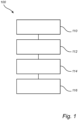
- the method 100 may be implemented by a general-purpose programmable computer, or in particular by the device 200 shown in figure 2 to be described below.
- the type of reinforcement learning scheme may for example be Q-learning or temporal-difference learning on the basis of a predefined reward function R ( s, a ) ; see R. S. Sutton et al., Reinforcement Learning, MIT Press (2018), ISBN 9780262039246 .
- the reward function R ( s , a ) may represent productivity minus cost.
- the productivity term(s) or factor(s) may be an (approximate) quantitative indicator of the amount of the utility task which is completed by the vehicles' movements. It may be a measure of the total distance travelled (e.g., vehicle-kilometers), total distance travelled by vehicles carrying payload, a passenger-distance measure (e.g., passenger-kilometers), a payload-distance measure (e.g., ton-kilometers), a payload quantity delivered to an intended recipient or the like.
- the cost term(s) or factor(s) in the reward function R ( s, a ) may reflect energy consumption, a projected maintenance demand in view of mechanical wear (e.g., total velocity variation, peak acceleration, braking events, number of load cycles on structural elements) or chemical wear (e.g., exposure to sunlight, corrosive fluids) and/or safety risks (e.g., minimum vehicle separation).
- Suitable training data for the reinforcement learning in step 110 may be obtained by running a large number of computer simulations of traffic based on a mathematical model of the vehicles and planning nodes, e.g., a road-network model. Recorded observations of real vehicle movements in an environment are an alternative source of training data. Hybrids of these are possible too, for instance, to use real-world observations as initial values to the computer simulation.
- the state-action value function Q ( s, a ) obtained in the first step 110 depends on node occupancies s and on motion commands a to be given within the planning horizon.
- the objective function includes at least one command-independent term Q L ( s ) , which penalizes node occupancies with too small inter-vehicle gaps, and at least one command-dependent term Q S ( s, a ) .
- the command-independent term Q L (s) and the command-dependent term Q S ( s, a ) may respectively represent a long-term and a short-term memory of the traffic planning method 100.
- command-dependent term Q S ( s, a ) It is primarily the command-dependent term Q S ( s, a ) that may be obtained by means of reinforcement training according to the reward function R ( s,a ) .
- the command-dependent term Q S ( s, a ) may furthermore be updated after step 110 (training phase) has ended, i.e. in operation, whereas the command-independent term Q L ( s ) may remain constant between planning calls.
- the command-independent term Q L ( s ) may be defined by reference to a gap-balancing indicator SoB ( s ) which, for a state s , expresses the degree of desirability of the prevailing inter-vehicle gaps as a number.
- the inter-vehicle gap may be defined as the distance to the vehicle immediately ahead of it.
- the gap of v3 at wp6 is determined by v4 at wp8, since this is v3's unique direction of movement.
- the gap may be defined as the number of intervening waypoints, i.e., one (wpy).
- Vehicle v1 at wp1 can move via wp2 to wp3 or directly to wp3, and from wp3 to either wp4 or wp6.
- a unique gap size among these four options may be determined based on a predefined rule.
- the rule may stipulate, for example, that the gap-balancing indicator SoB ( s ) shall be based on the minimum, maximum or average gap across the available routing options.
- the rule may be based on a predefined standard circuit for traversing the waypoints.
- the standard circuit may correspond to the preferred route for carrying out a utility task, such as loading, unloading or moving.
- a gap size in the sense of one of these definitions may refer to a distance or a time separation. If time is used to quantify the gap, it may correspond to the time needed for the rear vehicle to reach the momentary position of the vehicle immediately in front ahead of it at the rear vehicle's current speed. Alternatively, the relative speed of the front and rear vehicles may be used as basis. For example, if the front vehicle is moving more slowly, the gap-size time may correspond to the time to collision absent any intervention, and in the opposite case the gap-size time may be set to a maximum value.
- the gap-balancing indicator SoB provides a convenient basis for determining a suitable sequence of motion commands by optimization.
- the gap-balancing indicator SoB ( s ) can be defined so that it assumes values in [0,1], where the value 1 corresponds to a state s such that no further balancing is possible and the value 0 represents the opposite.
- the gap-balancing indicator SoB ( s ) may purposefully be defined to be 1 if a state s is wellbalanced but not ideally balanced, namely, if the owner of the traffic system does not find it worthwhile or meaningful to spend resources on further intervention aiming to balance the node occupancies of the vehicles.
- a gap-balancing indicator SoB 1 can be constructed based on a standard deviation D ( s ) of the sizes of the inter-vehicle gaps.
- D ( s ) are variance, variability coefficient, range, interquartile range, and other variability measures.
- a gap-balancing indicator of this type may cause the method 100 to return motion commands tending to distribute the available total gap size L (in time or distance) equally among the vehicles 299.
- SoB 2 which is proportional to the minimum gap size among the vehicles 299.
- the command-independent term Q L ( s ) includes a composition of a gap-balancing indicator SoB and a step-like function, such as a smooth activation function. This may improve the stability of the traffic system when controlled by outputs of the method 100.
- Suitable step-like functions may be a rectified linear unit (ReLU) activation function or modified ReLU
- Q L s Q L min e ⁇ ⁇ ⁇ SoB s 2 , ⁇ > 0
- a sigmoid function such as a logistic function
- Q L s 1 1 + e ⁇ ⁇ ⁇ SoB s , ⁇ > 0 , scaled variants of the above functions, or a combination of these.
- An advantageous option is the following combination of two modified ReLUs composed with the above-defined gap-balancing indicators SoB 1 , SoB 2 :
- Q L s mReLU SoB 1 s ; thr D , k D + mReLU SoB 2 s ; thr mingap , k mingap
- Q L ( s 0 ) -k D thr D - k mingap thr mingap .
- the thresholds thr D , thr mingap represents satisfactory gap balancing, beyond which no further improvement is deemed meaningful or worthwhile.
- the slopes k D , k mingap are preferably set large enough that the improvement of SoB in Q L ( s ) outweighs the reward in Q S ( s, a ) for moving one vehicle between two waypoints, so that the long-term memory is certain to influence the determination of motion commands. This may be achieved by trial and error, possibly in view of the number of vehicles, geometry of the traffic system and the definition of the reward function R ( s, a ) .
- This proposed combination of two modified ReLUs is able to manage two desirable goals at once: to maximize the gap spread (i.e., gaps are distributed evenly) and keep vehicles from moving at so small distance that a queue may form.
- the initial node occupancies of the vehicles are obtained.
- the node occupancies may be represented as a data structure associating each vehicle with a planning node, similar to the occupancy function O(-) introduced above. Ways of obtaining the node occupancies are described below in connection with figure 2 .
- a sequence of motion commands a is determined by optimizing the state-action value function Q ( s, a ) .
- the optimization process may include executing a planning algorithm of any of the types discussed above. It is noted that the optimization process may be allowed to execute until a convergence criterion is met, until an optimality criterion is fulfilled and/or until a predefined time has elapsed. Actually reaching optimality is no necessary condition under the present invention.
- the optimization process is normally restricted to a planning horizon (or search depth), which may be determined in view of a computational budget (see applicant's co-pending application EP21175955.0 ) or fixed.
- a fourth step 116 of the method 100 the command-dependent term Q S ( s, a ) of the state-action value function Q ( s, a ) is updated on the basis of the reward function R ( s, a ) for every iteration of the third step 114.
- a simplified reward function R ⁇ ( s, a ) can be used which largely reflects the same desirables as R ( s, a ) but is cheaper to evaluate.
- the command-independent term Q L ( s ) is preferably exempted from said iterative updating 116, recalling that its role is to act as long-term memory of the traffic planning method 100. This does not rule out the possibility of adjusting the command-independent term Q L ( s ) during ongoing traffic planning, though preferably this is done less frequently than at every execution cycle of the command-determining step 114.
- the step 110 may constitute a training phase taking place prior to actual operation and need not be repeated after for each commissioned copy of a traffic planner product.
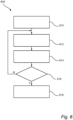
- the reinforcement learning step 110 and command-determining step 114 are performed within a Dyna-2 algorithm or an equivalent algorithm.
- a characteristic of the Dyna-2 algorithm is that learning occurs both while the machine-learning model is being built (training phase) and while it interacts with the system to be controlled.
- Figure 6 is a flowchart of an example Dyna-2 algorithm 600, which includes the following steps:
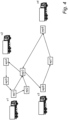
- FIG. 2 shows, in accordance with a further embodiment, a device 200 for controlling a plurality of vehicles 299 sharing a set of planning nodes.
- the device 200 which may be referred to as a traffic planner, has a first interface 210 configured to receive initial node occupancies of the vehicles 299.
- it may further receive, for each vehicle, information representing a set of predefined commands v1.a1, v1.a2, v2.a1, v2.a2, which can be fed to the respective vehicles, and/or a mission (utility task) to be carried out may by the vehicles 299.
- a mission utility task
- the initial node occupancies may be obtained from a traffic control entity (not shown) communicating with the vehicles 299, from sensors (not shown) detecting the positions of the vehicles 299, or from a reply to a self-positioning query issued to the vehicles 299.
- the optional information may be entered into the first interface 210 by an operator or provided as configuration data once it is known which vehicles 299 will form the fleet.
- the device 200 further has a second interface 220 configured to feed commands selected from said predefined commands to said plurality of vehicles, as well as processing circuitry 230 configured to perform the method 100 described above.
- Figure 2 shows direct wireless links from the second interface 220 to the vehicles 299.
- the second interface 220 may instead feed sequences of the predefined commands to the traffic control entity, which takes care of the delivery of the commands to the vehicles 299.
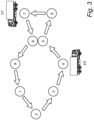
- FIG. 3 shows a road network where two vehicles v1, v2 can move freely along the arrows between planning nodes (or waypoints) 1-9. There are no junctions; rather, the arrows define a circuit by which each vehicle traverses all nine planning nodes. If the inter-vehicle gaps are defined as the number of intervening planning nodes along the circuit, the gaps are given by O v 1 ⁇ O v 2 mod9 ⁇ 1 and O v 2 ⁇ O v 1 mod 9 ⁇ 1 , where 0 ( ⁇ ) is the occupancy function introduced above. The vehicles v1, v2 are not allowed to occupy planning nodes 5 and 8 contemporaneously.
- Figure 5 shows a truck 500, a bus 502 and a construction equipment vehicle 504.
- a fleet of vehicles of one or more of these types, whether they are autonomous or conventional, can be controlled in a centralized fashion using the method 100 or the device 200 described above.
Landscapes
- Engineering & Computer Science (AREA)
- Physics & Mathematics (AREA)
- General Physics & Mathematics (AREA)
- Automation & Control Theory (AREA)
- Remote Sensing (AREA)
- Radar, Positioning & Navigation (AREA)
- Aviation & Aerospace Engineering (AREA)
- Business, Economics & Management (AREA)
- Health & Medical Sciences (AREA)
- Artificial Intelligence (AREA)
- Evolutionary Computation (AREA)
- Game Theory and Decision Science (AREA)
- Medical Informatics (AREA)
- Traffic Control Systems (AREA)
Claims (14)
- Verkehrsplanungsverfahren (100) zur Steuerung einer Vielzahl von Fahrzeugen (v1, v2, v3, v4), wobei jedes Fahrzeug einen Knoten in einem gemeinsam genutzten Satz von Planungsknoten (wp1, wp2, ..., wp8) belegt und entlang vordefinierter Linien zwischen Paaren der Knoten in Übereinstimmung mit einer begrenzten Anzahl von Fahrbefehlen (v1.a1, v1.a2, v2.a1, v2.a2) zu anderen Knoten bewegbar ist, das Verfahren umfassend:Erhalten (112) der anfänglichen Knotenbelegungen der Fahrzeuge; undBestimmen (114) einer Folge von Fahrbefehlen durch Optimieren einer Aktionswertfunktion (Q(s, a)), die von den Knotenbelegungen(s) und den zu erteilenden Fahrbefehlen (a) abhängt,dadurch gekennzeichnet, dass die Aktionswertfunktion mindestens eine befehlsunabhängige Bedingung (QL (s)), die Knotenbelegungen mit zu kleinen Fahrzeugabständen bestraft, und mindestens eine befehlsabhängige Bedingung (QS (s, a)) enthält.
- Verfahren nach Anspruch 1, wobei das Bestimmen (114) wiederholt ausgeführt wird und die befehlsabhängige Bedingung (Qs (s, a)) auf der Grundlage einer vordefinierten Belohnungsfunktion nach jedem Ausführungszyklus des Bestimmens (114) aktualisiert (116) wird.
- Verfahren nach Anspruch 2, wobei die befehlsunabhängige Bedingung (QL (s)) von der genannten Aktualisierung (116) ausgenommen ist.
- Verfahren nach Anspruch 2 oder 3, wobei die Belohnungsfunktion Produktivität minus Kosten darstellt.
- Verfahren nach einem der vorhergehenden Ansprüche, wobei die befehlsunabhängige Bedingung (QL (s)) einen Abstand zwischen den Fahrzeugen, ausgedrückt als zeitlicher Abstand der Fahrzeuge in der jeweiligen Bewegungsrichtung, bestraft.
- Verfahren nach einem der vorhergehenden Ansprüche, wobei die befehlsunabhängige Bedingung (QL (s)) von einem Lücken-Ausgleich-Indikator abhängt (SoB(s)), der zu kleine Lücken und/oder ungleichmäßig verteilte Lücken bestraft.
- Verfahren nach Anspruch 6, wobei der Lücken-Ausgleich-Indikator (SoB(s)) von einem Variabilitätsmaß der Lückengrößen abhängt, wie beispielsweise einer Standardabweichung der Lückengrößen.
- Verfahren nach Anspruch 6 oder 7, wobei die befehlsunabhängige Bedingung (QL (s)) eine Zusammensetzung des Lücken-Ausgleich-Indikators (SoB(s)) mit mindestens einer der folgenden Funktionen enthält:eine gleichgerichtete lineare Einheit, ReLU, Aktivierungsfunktion (QL (s) = mReLU (SoB(s); thr, k), wobei 0 < thr ≤ 1,k > 0 ein Schwellenwert bzw. eine Steigung sind;eine Gaußfunktion (
 eine Sigmoidfunktion (
- Verfahren nach einem der vorhergehenden Ansprüche, ferner umfassend das Erhalten der Aktionswertfunktion durch einen vorhergehenden Schritt des Verstärkungslernens (110), wie beispielsweise Q-Lernen oder Zeitdifferenzlernen auf der Grundlage einer vordefinierten Belohnungsfunktion.
- Verfahren nach einem der vorhergehenden Ansprüche, wobei das Bestimmen (114) einer Folge von Fahrbefehlen innerhalb eines Dyna-2-Algorithmus (600) durchgeführt wird.
- Verfahren nach Anspruch 10, der sich auf Anspruch 9 bezieht, wobei ferner das Verstärkungslernen (110) innerhalb des Dyna-2-Algorithmus durchgeführt wird.
- Verfahren nach einem der vorhergehenden Ansprüche, wobei das Fahrzeug ein autonomes Fahrzeug ist.
- Vorrichtung (200), die konfiguriert ist, um eine Vielzahl von Fahrzeugen (v1, v2, V3, v4) zu steuern, wobei jedes Fahrzeug einen Knoten in einem gemeinsam genutzten Satz von Planungsknoten (wp1, wp2, ..., wp8) belegt und entlang vordefinierter Linien zwischen Paaren der Knoten in Übereinstimmung mit einer begrenzten Anzahl von Fahrbefehlen (v1.a1, v1.a2, v2.a1, v2.a2) zu anderen Knoten bewegbar ist, die Vorrichtung umfassend:eine erste Schnittstelle (210), die konfiguriert ist, um anfängliche Knotenbelegungen der Fahrzeuge zu empfangen;eine zweite Schnittstelle (220), die konfiguriert ist, um Fahrbefehle, die aus der einer begrenzten Anzahl ausgewählt werden, an die Vielzahl von Fahrzeugen weiterzuleiten; undeine Verarbeitungsschaltung (230), die konfiguriert ist, um das Verfahren nach einem der vorhergehenden Ansprüche durchzuführen.
- Computerprogramm mit Anweisungen, die bei der Ausführung die Vorrichtung nach Anspruch 13 veranlassen, das Verfahren nach einem der Ansprüche 1 bis 12 auszuführen.
Priority Applications (2)
| Application Number | Priority Date | Filing Date | Title |
|---|---|---|---|
| EP21183223.3A EP4113241B1 (de) | 2021-07-01 | 2021-07-01 | Verfahren und system zur steuerung einer vielzahl von fahrzeugen, insbesondere autonomen fahrzeugen |
| US17/808,615 US20230004163A1 (en) | 2021-07-01 | 2022-06-24 | Method and system for controlling a plurality of vehicles, in particular autonomous vehicles |
Applications Claiming Priority (1)
| Application Number | Priority Date | Filing Date | Title |
|---|---|---|---|
| EP21183223.3A EP4113241B1 (de) | 2021-07-01 | 2021-07-01 | Verfahren und system zur steuerung einer vielzahl von fahrzeugen, insbesondere autonomen fahrzeugen |
Publications (3)
| Publication Number | Publication Date |
|---|---|
| EP4113241A1 EP4113241A1 (de) | 2023-01-04 |
| EP4113241C0 EP4113241C0 (de) | 2023-08-16 |
| EP4113241B1 true EP4113241B1 (de) | 2023-08-16 |
Family
ID=84272922
Family Applications (1)
| Application Number | Title | Priority Date | Filing Date |
|---|---|---|---|
| EP21183223.3A Active EP4113241B1 (de) | 2021-07-01 | 2021-07-01 | Verfahren und system zur steuerung einer vielzahl von fahrzeugen, insbesondere autonomen fahrzeugen |
Country Status (2)
| Country | Link |
|---|---|
| US (1) | US20230004163A1 (de) |
| EP (1) | EP4113241B1 (de) |
Families Citing this family (2)
| Publication number | Priority date | Publication date | Assignee | Title |
|---|---|---|---|---|
| EP4462403B1 (de) * | 2023-05-12 | 2025-07-30 | Volvo Autonomous Solutions AB | Verkehrsplanungsverfahren für eine fahrzeugflotte |
| EP4462404B1 (de) * | 2023-05-12 | 2025-11-12 | Volvo Autonomous Solutions AB | Verkehrsplanungsverfahren für eine fahrzeugflotte |
Family Cites Families (14)
| Publication number | Priority date | Publication date | Assignee | Title |
|---|---|---|---|---|
| US5179329A (en) * | 1989-04-25 | 1993-01-12 | Shinko Electric Co., Ltd. | Travel control method, travel control device, and mobile robot for mobile robot systems |
| ITVR20130178A1 (it) * | 2013-07-26 | 2015-01-27 | Elettric 80 Spa | Dispositivo e metodo per l'ottimizzazione della movimentazione di veicoli a guida automatica, e simili |
| US9191304B1 (en) * | 2013-08-12 | 2015-11-17 | The United States Of America As Represented By The Secretary Of The Navy | Reinforcement learning-based distributed network routing method utilizing integrated tracking and selective sweeping |
| US10019006B2 (en) * | 2015-04-08 | 2018-07-10 | University Of Maryland, College Park | Surface vehicle trajectory planning systems, devices, and methods |
| CN111758017A (zh) * | 2018-02-28 | 2020-10-09 | 索尼公司 | 信息处理装置、信息处理方法、程序及移动体 |
| US10860023B2 (en) * | 2018-06-25 | 2020-12-08 | Mitsubishi Electric Research Laboratories, Inc. | Systems and methods for safe decision making of autonomous vehicles |
| DE102018212318B4 (de) * | 2018-07-24 | 2023-09-28 | Denso Corporation | Adaptive geschwindigkeitsregelung |
| US10466716B1 (en) * | 2018-09-05 | 2019-11-05 | Chongqing Jinkang New Energy Vehicle Co., Ltd | Vehicle command generation using vehicle-to-infrastructure communications and deep networks |
| GB2585371B8 (en) * | 2019-07-02 | 2022-01-19 | Seyo Ltd | Distributed event-based coordination model |
| US11537127B2 (en) * | 2019-09-12 | 2022-12-27 | Uatc, Llc | Systems and methods for vehicle motion planning based on uncertainty |
| CN110580196B (zh) * | 2019-09-12 | 2021-04-06 | 北京邮电大学 | 一种实现并行任务调度的多任务强化学习方法 |
| CN114514758A (zh) * | 2019-11-04 | 2022-05-17 | 英特尔公司 | 交通工具网络中的操纵协调服务 |
| CN112015174B (zh) * | 2020-07-10 | 2022-06-28 | 歌尔股份有限公司 | 一种多agv运动规划方法、装置和系统 |
| US11541909B1 (en) * | 2020-08-28 | 2023-01-03 | Zoox, Inc. | Detection of object awareness and/or malleability to state change |
-
2021
- 2021-07-01 EP EP21183223.3A patent/EP4113241B1/de active Active
-
2022
- 2022-06-24 US US17/808,615 patent/US20230004163A1/en not_active Abandoned
Also Published As
| Publication number | Publication date |
|---|---|
| EP4113241C0 (de) | 2023-08-16 |
| US20230004163A1 (en) | 2023-01-05 |
| EP4113241A1 (de) | 2023-01-04 |
Similar Documents
| Publication | Publication Date | Title |
|---|---|---|
| Hodgson et al. | Developing control rules for an AGV using Markov decision processes | |
| CN108267149B (zh) | 多移动机器人的冲突管理方法及系统 | |
| Skinner et al. | Optimisation for job scheduling at automated container terminals using genetic algorithm | |
| EP4113241B1 (de) | Verfahren und system zur steuerung einer vielzahl von fahrzeugen, insbesondere autonomen fahrzeugen | |
| US20210325862A1 (en) | Safeguarding resources of physical entities in a shared environment | |
| Dan et al. | Persistent object search and surveillance control with safety certificates for drone networks based on control barrier functions | |
| US20220383740A1 (en) | Method and system for controlling a plurality of vehicles, in particular autonomous vehicles | |
| Cao et al. | Research on global optimization method for multiple AGV collision avoidance in hybrid path | |
| Eilbrecht et al. | Optimization-based maneuver automata for cooperative trajectory planning of autonomous vehicles | |
| CN116090680A (zh) | 在受限区域中协调车辆路线的方法和设备 | |
| Gunarathna et al. | Real-time intelligent autonomous intersection management using reinforcement learning | |
| Yang et al. | Dynamic time estimation based AGV dispatching algorithm in automated container terminal | |
| Liu et al. | Simultaneous planning and scheduling for multi-autonomous vehicles | |
| CN115480567B (zh) | 路径规划方法及装置、机器人及计算机可读存储介质 | |
| Pfrommer et al. | Autonomously organized block stacking warehouses: A review of decision problems and major challenges | |
| CN119692739B (zh) | 基于替代图模型的干散货码头堆场无人卡车调度优化方法 | |
| Xia et al. | A multi-AGV optimal scheduling algorithm based on particle swarm optimization | |
| EP4462404B1 (de) | Verkehrsplanungsverfahren für eine fahrzeugflotte | |
| EP4487080B1 (de) | Verfahren und vorrichtung zur lastbewussten planung von fahrzeugbewegungen | |
| Huang et al. | CoDe: A Cooperative and Decentralized Collision Avoidance Algorithm for Small-Scale UAV Swarms Considering Energy Efficiency | |
| Cicek et al. | MARL-PPS: Multi-agent reinforcement learning with periodic parameter sharing | |
| Gunarathna et al. | Intelligent autonomous intersection management | |
| EP4462403B1 (de) | Verkehrsplanungsverfahren für eine fahrzeugflotte | |
| Bastos et al. | Task Allocation Algorithms for Drone Parcel Delivery Systems | |
| Bhamidipati et al. | Q-Learning-Based Dynamic Drone Trajectory Planning in Uncertain Environments |
Legal Events
| Date | Code | Title | Description |
|---|---|---|---|
| PUAI | Public reference made under article 153(3) epc to a published international application that has entered the european phase |
Free format text: ORIGINAL CODE: 0009012 |
|
| STAA | Information on the status of an ep patent application or granted ep patent |
Free format text: STATUS: REQUEST FOR EXAMINATION WAS MADE |
|
| 17P | Request for examination filed |
Effective date: 20221107 |
|
| AK | Designated contracting states |
Kind code of ref document: A1 Designated state(s): AL AT BE BG CH CY CZ DE DK EE ES FI FR GB GR HR HU IE IS IT LI LT LU LV MC MK MT NL NO PL PT RO RS SE SI SK SM TR |
|
| GRAP | Despatch of communication of intention to grant a patent |
Free format text: ORIGINAL CODE: EPIDOSNIGR1 |
|
| STAA | Information on the status of an ep patent application or granted ep patent |
Free format text: STATUS: GRANT OF PATENT IS INTENDED |
|
| INTG | Intention to grant announced |
Effective date: 20230317 |
|
| GRAS | Grant fee paid |
Free format text: ORIGINAL CODE: EPIDOSNIGR3 |
|
| GRAA | (expected) grant |
Free format text: ORIGINAL CODE: 0009210 |
|
| STAA | Information on the status of an ep patent application or granted ep patent |
Free format text: STATUS: THE PATENT HAS BEEN GRANTED |
|
| AK | Designated contracting states |
Kind code of ref document: B1 Designated state(s): AL AT BE BG CH CY CZ DE DK EE ES FI FR GB GR HR HU IE IS IT LI LT LU LV MC MK MT NL NO PL PT RO RS SE SI SK SM TR |
|
| REG | Reference to a national code |
Ref country code: CH Ref legal event code: EP Ref country code: DE Ref legal event code: R096 Ref document number: 602021004283 Country of ref document: DE |
|
| REG | Reference to a national code |
Ref country code: IE Ref legal event code: FG4D |
|
| U01 | Request for unitary effect filed |
Effective date: 20230912 |
|
| U07 | Unitary effect registered |
Designated state(s): AT BE BG DE DK EE FI FR IT LT LU LV MT NL PT SE SI Effective date: 20230918 |
|
| PG25 | Lapsed in a contracting state [announced via postgrant information from national office to epo] |
Ref country code: GR Free format text: LAPSE BECAUSE OF FAILURE TO SUBMIT A TRANSLATION OF THE DESCRIPTION OR TO PAY THE FEE WITHIN THE PRESCRIBED TIME-LIMIT Effective date: 20231117 |
|
| PG25 | Lapsed in a contracting state [announced via postgrant information from national office to epo] |
Ref country code: IS Free format text: LAPSE BECAUSE OF FAILURE TO SUBMIT A TRANSLATION OF THE DESCRIPTION OR TO PAY THE FEE WITHIN THE PRESCRIBED TIME-LIMIT Effective date: 20231216 |
|
| PG25 | Lapsed in a contracting state [announced via postgrant information from national office to epo] |
Ref country code: RS Free format text: LAPSE BECAUSE OF FAILURE TO SUBMIT A TRANSLATION OF THE DESCRIPTION OR TO PAY THE FEE WITHIN THE PRESCRIBED TIME-LIMIT Effective date: 20230816 Ref country code: NO Free format text: LAPSE BECAUSE OF FAILURE TO SUBMIT A TRANSLATION OF THE DESCRIPTION OR TO PAY THE FEE WITHIN THE PRESCRIBED TIME-LIMIT Effective date: 20231116 Ref country code: IS Free format text: LAPSE BECAUSE OF FAILURE TO SUBMIT A TRANSLATION OF THE DESCRIPTION OR TO PAY THE FEE WITHIN THE PRESCRIBED TIME-LIMIT Effective date: 20231216 Ref country code: HR Free format text: LAPSE BECAUSE OF FAILURE TO SUBMIT A TRANSLATION OF THE DESCRIPTION OR TO PAY THE FEE WITHIN THE PRESCRIBED TIME-LIMIT Effective date: 20230816 Ref country code: GR Free format text: LAPSE BECAUSE OF FAILURE TO SUBMIT A TRANSLATION OF THE DESCRIPTION OR TO PAY THE FEE WITHIN THE PRESCRIBED TIME-LIMIT Effective date: 20231117 |
|
| PG25 | Lapsed in a contracting state [announced via postgrant information from national office to epo] |
Ref country code: PL Free format text: LAPSE BECAUSE OF FAILURE TO SUBMIT A TRANSLATION OF THE DESCRIPTION OR TO PAY THE FEE WITHIN THE PRESCRIBED TIME-LIMIT Effective date: 20230816 |
|
| PG25 | Lapsed in a contracting state [announced via postgrant information from national office to epo] |
Ref country code: ES Free format text: LAPSE BECAUSE OF FAILURE TO SUBMIT A TRANSLATION OF THE DESCRIPTION OR TO PAY THE FEE WITHIN THE PRESCRIBED TIME-LIMIT Effective date: 20230816 |
|
| PG25 | Lapsed in a contracting state [announced via postgrant information from national office to epo] |
Ref country code: SM Free format text: LAPSE BECAUSE OF FAILURE TO SUBMIT A TRANSLATION OF THE DESCRIPTION OR TO PAY THE FEE WITHIN THE PRESCRIBED TIME-LIMIT Effective date: 20230816 Ref country code: RO Free format text: LAPSE BECAUSE OF FAILURE TO SUBMIT A TRANSLATION OF THE DESCRIPTION OR TO PAY THE FEE WITHIN THE PRESCRIBED TIME-LIMIT Effective date: 20230816 Ref country code: ES Free format text: LAPSE BECAUSE OF FAILURE TO SUBMIT A TRANSLATION OF THE DESCRIPTION OR TO PAY THE FEE WITHIN THE PRESCRIBED TIME-LIMIT Effective date: 20230816 Ref country code: CZ Free format text: LAPSE BECAUSE OF FAILURE TO SUBMIT A TRANSLATION OF THE DESCRIPTION OR TO PAY THE FEE WITHIN THE PRESCRIBED TIME-LIMIT Effective date: 20230816 Ref country code: SK Free format text: LAPSE BECAUSE OF FAILURE TO SUBMIT A TRANSLATION OF THE DESCRIPTION OR TO PAY THE FEE WITHIN THE PRESCRIBED TIME-LIMIT Effective date: 20230816 |
|
| REG | Reference to a national code |
Ref country code: DE Ref legal event code: R097 Ref document number: 602021004283 Country of ref document: DE |
|
| PLBE | No opposition filed within time limit |
Free format text: ORIGINAL CODE: 0009261 |
|
| STAA | Information on the status of an ep patent application or granted ep patent |
Free format text: STATUS: NO OPPOSITION FILED WITHIN TIME LIMIT |
|
| 26N | No opposition filed |
Effective date: 20240517 |
|
| U20 | Renewal fee for the european patent with unitary effect paid |
Year of fee payment: 4 Effective date: 20240725 |
|
| PG25 | Lapsed in a contracting state [announced via postgrant information from national office to epo] |
Ref country code: MC Free format text: LAPSE BECAUSE OF FAILURE TO SUBMIT A TRANSLATION OF THE DESCRIPTION OR TO PAY THE FEE WITHIN THE PRESCRIBED TIME-LIMIT Effective date: 20230816 |
|
| REG | Reference to a national code |
Ref country code: CH Ref legal event code: PL |
|
| PG25 | Lapsed in a contracting state [announced via postgrant information from national office to epo] |
Ref country code: CH Free format text: LAPSE BECAUSE OF NON-PAYMENT OF DUE FEES Effective date: 20240731 |
|
| PG25 | Lapsed in a contracting state [announced via postgrant information from national office to epo] |
Ref country code: IE Free format text: LAPSE BECAUSE OF NON-PAYMENT OF DUE FEES Effective date: 20240701 |
|
| U20 | Renewal fee for the european patent with unitary effect paid |
Year of fee payment: 5 Effective date: 20250725 |
|
| PG25 | Lapsed in a contracting state [announced via postgrant information from national office to epo] |
Ref country code: CY Free format text: LAPSE BECAUSE OF FAILURE TO SUBMIT A TRANSLATION OF THE DESCRIPTION OR TO PAY THE FEE WITHIN THE PRESCRIBED TIME-LIMIT; INVALID AB INITIO Effective date: 20210701 |