EP4113234A1 - Equipment management device and method for generating equipment management screen - Google Patents
Equipment management device and method for generating equipment management screen Download PDFInfo
- Publication number
- EP4113234A1 EP4113234A1 EP20921201.8A EP20921201A EP4113234A1 EP 4113234 A1 EP4113234 A1 EP 4113234A1 EP 20921201 A EP20921201 A EP 20921201A EP 4113234 A1 EP4113234 A1 EP 4113234A1
- Authority
- EP
- European Patent Office
- Prior art keywords
- display
- equipment
- display size
- equipment management
- management screen
- Prior art date
- Legal status (The legal status is an assumption and is not a legal conclusion. Google has not performed a legal analysis and makes no representation as to the accuracy of the status listed.)
- Granted
Links
Images





Classifications
-
- G—PHYSICS
- G06—COMPUTING OR CALCULATING; COUNTING
- G06F—ELECTRIC DIGITAL DATA PROCESSING
- G06F3/00—Input arrangements for transferring data to be processed into a form capable of being handled by the computer; Output arrangements for transferring data from processing unit to output unit, e.g. interface arrangements
- G06F3/01—Input arrangements or combined input and output arrangements for interaction between user and computer
- G06F3/048—Interaction techniques based on graphical user interfaces [GUI]
- G06F3/0481—Interaction techniques based on graphical user interfaces [GUI] based on specific properties of the displayed interaction object or a metaphor-based environment, e.g. interaction with desktop elements like windows or icons, or assisted by a cursor's changing behaviour or appearance
- G06F3/04817—Interaction techniques based on graphical user interfaces [GUI] based on specific properties of the displayed interaction object or a metaphor-based environment, e.g. interaction with desktop elements like windows or icons, or assisted by a cursor's changing behaviour or appearance using icons
-
- F—MECHANICAL ENGINEERING; LIGHTING; HEATING; WEAPONS; BLASTING
- F24—HEATING; RANGES; VENTILATING
- F24F—AIR-CONDITIONING; AIR-HUMIDIFICATION; VENTILATION; USE OF AIR CURRENTS FOR SCREENING
- F24F11/00—Control or safety arrangements
- F24F11/50—Control or safety arrangements characterised by user interfaces or communication
- F24F11/52—Indication arrangements, e.g. displays
-
- F—MECHANICAL ENGINEERING; LIGHTING; HEATING; WEAPONS; BLASTING
- F24—HEATING; RANGES; VENTILATING
- F24F—AIR-CONDITIONING; AIR-HUMIDIFICATION; VENTILATION; USE OF AIR CURRENTS FOR SCREENING
- F24F11/00—Control or safety arrangements
- F24F11/50—Control or safety arrangements characterised by user interfaces or communication
- F24F11/52—Indication arrangements, e.g. displays
- F24F11/523—Indication arrangements, e.g. displays for displaying temperature data
-
- G—PHYSICS
- G06—COMPUTING OR CALCULATING; COUNTING
- G06F—ELECTRIC DIGITAL DATA PROCESSING
- G06F3/00—Input arrangements for transferring data to be processed into a form capable of being handled by the computer; Output arrangements for transferring data from processing unit to output unit, e.g. interface arrangements
- G06F3/01—Input arrangements or combined input and output arrangements for interaction between user and computer
- G06F3/048—Interaction techniques based on graphical user interfaces [GUI]
- G06F3/0481—Interaction techniques based on graphical user interfaces [GUI] based on specific properties of the displayed interaction object or a metaphor-based environment, e.g. interaction with desktop elements like windows or icons, or assisted by a cursor's changing behaviour or appearance
- G06F3/0482—Interaction with lists of selectable items, e.g. menus
-
- G—PHYSICS
- G06—COMPUTING OR CALCULATING; COUNTING
- G06F—ELECTRIC DIGITAL DATA PROCESSING
- G06F3/00—Input arrangements for transferring data to be processed into a form capable of being handled by the computer; Output arrangements for transferring data from processing unit to output unit, e.g. interface arrangements
- G06F3/01—Input arrangements or combined input and output arrangements for interaction between user and computer
- G06F3/048—Interaction techniques based on graphical user interfaces [GUI]
- G06F3/0484—Interaction techniques based on graphical user interfaces [GUI] for the control of specific functions or operations, e.g. selecting or manipulating an object, an image or a displayed text element, setting a parameter value or selecting a range
- G06F3/04847—Interaction techniques to control parameter settings, e.g. interaction with sliders or dials
-
- G—PHYSICS
- G06—COMPUTING OR CALCULATING; COUNTING
- G06F—ELECTRIC DIGITAL DATA PROCESSING
- G06F3/00—Input arrangements for transferring data to be processed into a form capable of being handled by the computer; Output arrangements for transferring data from processing unit to output unit, e.g. interface arrangements
- G06F3/01—Input arrangements or combined input and output arrangements for interaction between user and computer
- G06F3/048—Interaction techniques based on graphical user interfaces [GUI]
- G06F3/0487—Interaction techniques based on graphical user interfaces [GUI] using specific features provided by the input device, e.g. functions controlled by the rotation of a mouse with dual sensing arrangements, or of the nature of the input device, e.g. tap gestures based on pressure sensed by a digitiser
- G06F3/0488—Interaction techniques based on graphical user interfaces [GUI] using specific features provided by the input device, e.g. functions controlled by the rotation of a mouse with dual sensing arrangements, or of the nature of the input device, e.g. tap gestures based on pressure sensed by a digitiser using a touch-screen or digitiser, e.g. input of commands through traced gestures
- G06F3/04886—Interaction techniques based on graphical user interfaces [GUI] using specific features provided by the input device, e.g. functions controlled by the rotation of a mouse with dual sensing arrangements, or of the nature of the input device, e.g. tap gestures based on pressure sensed by a digitiser using a touch-screen or digitiser, e.g. input of commands through traced gestures by partitioning the display area of the touch-screen or the surface of the digitising tablet into independently controllable areas, e.g. virtual keyboards or menus
-
- G—PHYSICS
- G06—COMPUTING OR CALCULATING; COUNTING
- G06T—IMAGE DATA PROCESSING OR GENERATION, IN GENERAL
- G06T11/00—Two-dimensional [2D] image generation
-
- G—PHYSICS
- G06—COMPUTING OR CALCULATING; COUNTING
- G06T—IMAGE DATA PROCESSING OR GENERATION, IN GENERAL
- G06T11/00—Two-dimensional [2D] image generation
- G06T11/60—Creating or editing images; Combining images with text
- G06T11/65—Creating or editing images; Combining images with text on geographic maps
-
- G—PHYSICS
- G06—COMPUTING OR CALCULATING; COUNTING
- G06T—IMAGE DATA PROCESSING OR GENERATION, IN GENERAL
- G06T3/00—Geometric image transformations in the plane of the image
- G06T3/40—Scaling of whole images or parts thereof, e.g. expanding or contracting
-
- H—ELECTRICITY
- H04—ELECTRIC COMMUNICATION TECHNIQUE
- H04Q—SELECTING
- H04Q9/00—Arrangements in telecontrol or telemetry systems for selectively calling a substation from a main station, in which substation desired apparatus is selected for applying a control signal thereto or for obtaining measured values therefrom
-
- G—PHYSICS
- G06—COMPUTING OR CALCULATING; COUNTING
- G06T—IMAGE DATA PROCESSING OR GENERATION, IN GENERAL
- G06T2200/00—Indexing scheme for image data processing or generation, in general
- G06T2200/24—Indexing scheme for image data processing or generation, in general involving graphical user interfaces [GUIs]
Definitions
- Embodiments of the present invention relate to an equipment management apparatus and an equipment management screen generating method.
- a lot of equipment devices are usually installed in large buildings such as commercial facilities and office buildings, and those equipment devices are managed centrally by a central management apparatus which is an equipment management apparatus.
- the central management apparatus sequentially obtains and stores operating state information from the respective equipment devices.
- a manager is able to perform operations of monitoring the operating state information of the equipment devices and changing setting information, using the central management apparatus.
- a manager displays an equipment management screen which uses a floor configuration diagram in a building, on a liquid crystal display of the central management apparatus.
- icons indicating the equipment devices are superimposed on the floor configuration diagram at the positions corresponding to the installation sites of the equipment devices.
- the operating state information of the desired equipment device is displayed.
- a manager is able to perform management work for the equipment devices by confirming the operating state information and changing the setting information with respect to the displayed equipment device.
- the central management apparatus also may be capable of communicating with an operation terminal with which the manager of the equipment devices performs equipment management, and the operation terminal may be used as an equipment management apparatus by allowing the operation terminal to perform displays and operations similar to the central management apparatus on a screen of the operation terminal.
- Patent Literature 1 Japanese Unexamined Patent Application Publication No. 2009-134469
- Equipment management apparatuses such as the equipment management apparatus described above sometimes manage equipment devices by a group such as stores in a building or offices. At that time, there is a problem that the manager cannot recognize how the equipment devices are grouped from the equipment management screen which uses a floor configuration diagram and thus the manager sometimes faces difficulties in performing operations by group.
- the present invention has been created in view of the above circumstances and aims to provide an equipment management apparatus and an equipment management screen generating method capable of improving the operability of management operations of equipment devices in a large building on a touch panel.
- an equipment management apparatus includes: a display configured to display an equipment management screen in which icons indicating equipment devices and having a first display size are superimposed on a floor configuration diagram of a building at positions corresponding to installation sites of the equipment devices; an operation detector configured to detect an operation on the equipment management screen displayed on the display; a device classification information storage configured to store device classification information in which the equipment devices are classified into groups; and a display information generator configured to, upon detection by the operation detector of an operation of one of icons indicating the equipment devices on the equipment management screen displayed on the display, change a display size of the operated icon from a first display size to a second display size larger than the first display size, and display an operation button for implementing settings of the equipment device at a prescribed position on the equipment management screen in a superimposed manner, and upon detection by the operation detector of an operation of specifying display of a group to which the equipment device corresponding to the operated icon belongs, identify all equipment devices belonging to the specified group based on the device classification information stored in the device classification information storage
- An equipment management screen generating method is performed by an equipment management apparatus including: a display configured to display an equipment management screen in which icons indicating equipment devices and having a first display size are superimposed on a floor configuration diagram of a building at positions corresponding to installation sites of the equipment devices; an operation detector configured to detect an operation on the equipment management screen displayed on the display; and a device classification information storage configured to store device classification information in which the equipment devices are classified into groups, the method comprising: upon detection by the operation detector of an operation of one of icons indicating the equipment devices on the equipment management screen displayed on the display, changing a display size of the operated icon from a first display size to a second display size larger than the first display size, and displaying an operation button for implementing settings of the equipment device at a prescribed position on the equipment management screen in a superimposed manner; and upon detection by the operation detector of an operation of specifying display of a group to which the equipment device corresponding to the operated icon belongs, identifying all equipment devices belonging to the specified group based on the device classification information stored in the device
- An air conditioning system 1 includes: air conditioners 10-1 to 10-n installed in a building; a controller 20 serving as a central management apparatus connected to the air conditioners 10-1 to 10-n; wireless communication access points 40-1 to 40-n connected to the controller 20 via a hub 30; a tablet terminal 50-1 wirelessly connected to the access point 40-1; a tablet terminal 50-2 wirelessly connected to the access point 40-2; a tablet terminal 50-3 wirelessly connected to the access point 40-3; and a personal computer 50-4 wirelessly connected to the access point 40-4.
- the controller 20, the tablet terminals 50-1 to 50-3, and the personal computer 50-4 are operated by a manager of the air conditioning system 1.
- the air conditioners 10-1 to 10-n installed in the building correspond to equipment devices.
- the controller 20 includes: a touch panel 21 with a liquid crystal display screen, a device classification information storage 22, a display information generator 23, a communicator 24, and a control information generator 25.
- the touch panel 21 includes an operation detector 211 and a display 212.
- the operation detector 211 detects a touch operation by the manager.
- the display 212 displays display information provided to the manager.
- the device classification information storage 22 stores device classification information in which the air conditioners 10-1 to 10-n are classified into groups.
- the display information generator 23 generates, as the display information, a management screen of the air conditioners 10-1 to 10-n and operating state information of a specified air conditioner based on operation information detected by the operation detector 211.
- the communicator 24 communicates with the air conditioners 10-1 to 10-n, the tablet terminals 50-1 to 50-3, and the personal computer 50-4.
- the control information generator 25 generates operational control information of the air conditioners 10-1 to 10-n based on the operation information detected by the operation detector 211.
- the tablet terminals 50-1 to 50-3 and the personal computer 50-4 transmit the operational control information for operational control to the air conditioners 10-1 to 10-n as required, and obtains and displays the operating state information of the air conditioners 10-1 to 10-n, through communication with the air conditioners 10-1 to 10-n via the controller 20.
- the air conditioning system 1 is installed in a large commercial facility.
- the operational control information for controlling operations of the air conditioners 10-1 to 10-n is transmitted as required and the operating state information of the air conditioners 10-1 to 10-n is obtained and stored at prescribed time intervals by the controller 20.
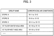
- the air conditioners 10-1 to 10-n are classified depending on the installation sites thereof into groups by stores or predetermined areas (such as a store A, a store B, a store C, a first floor center aisle area, and a first floor west aisle area) in the commercial facility equipped with the air conditioning system 1 is stored as the device classification information in the device classification information storage 22 of the controller 20.
- the air conditioners 10-1 to 10-5 correspond to a group indicating the air conditioners installed in a store A (a store A group)
- the air conditioners 10-6 to 10-10 correspond to a group indicating the air conditioners installed in a store B (a store B group)
- the air conditioners 10-11 to 10-15 correspond to a group indicating the air conditioners installed in a store C (a store C group)
- the air conditioners 10-16 to 10-18 correspond to a group indicating the air conditioners installed in a first floor center aisle area (a first floor center aisle area group)
- the air conditioners 10-19 to 10-21 correspond to a group indicating the air conditioners installed in a first floor west aisle area (a first floor west aisle area group).
- step S1 when the manager performs an operation of displaying the management screen of the air conditioners 10-1 to 10-n on the touch panel 21 of the controller 20 (step S1: YES), operation information is detected by the operation detector 211 and obtained by the display information generator 23.
- the display information generator 23 generates a base air conditioner management screen as a corresponding equipment management screen.
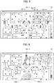
- air conditioner icons 101-1 to 101-n indicating the respective air conditioners and having a first display size "medium" are superimposed on a floor configuration diagram (floor layout diagram) of the building at positions corresponding to the installation sites of the respective air conditioners 10-1 to 10-n.
- the generated air conditioner management screen is displayed on the touch panel 21 by the display 212 as illustrated in Fig. 5 , for example (step S2).
- the air conditioner icons that are solid black circles indicate power-on states of the corresponding air conditioners 10
- the air conditioner icons that are white circles indicate power-off states of the corresponding air conditioners 10.
- step S3 When the manager performs a touch operation of any of the air conditioner icons, for example, the air conditioner icon 101-1 corresponding to the air conditioner 10-1 on the base air conditioner management screen displayed on the touch panel 21 (step S3: YES), operation information is detected by the operation detector 211 and obtained by the display information generator 23.
- the display information generator 23 Upon obtaining information indicating detection of the touch operation of the air conditioner icon 101-1 on the touch panel 21, the display information generator 23 updates the display information such that the display size of the air conditioner icon 101-1 displayed on the air conditioner management screen is changed to a second display size "large" that is larger than the first display size, the air conditioner icon 101-1 is highlighted by lighting up the region therearound, and an operation button 102-1 for implementing operations and settings of the corresponding air conditioner 10-1 and a group display button 103-1 for instructing display of the group to which the air conditioner 10-1 belongs are displayed at the bottom of the air conditioner management screen in a superimposed manner.
- the current operating state (power-on state / power-off state) of the corresponding air conditioner 10-1 and setting information (set temperature or the like) are displayed.
- the generated display information of the air conditioner management screen is displayed on the touch panel 21 by the display 212 as illustrated in Fig. 6 , for example (step S4).
- step S5 When the manager performs an operation with respect to the operations and settings of the corresponding air conditioner 10-1, for example, a power-off operation by means of the operation button 102-1 on the base air conditioner management screen displayed on the touch panel 21 (step S5: YES), the operation is detected by the operation detector 211 and a power-off instruction for the corresponding air conditioner 10-1 is generated as control information by the control information generator 25. The generated control information is transmitted from the communicator 24 to the corresponding air conditioner 10-1, and the power state of the corresponding air conditioner 10-1 is turned to an off state (step S6).
- the display information generator 23 returns the display size of the air conditioner icon 101-1 to the first display size "medium”, terminates the lighting up of the region around the air conditioner icon 101-1, terminates the display of the operation button 102-1, and then returns the display of the touch panel 21 to the base air conditioner management screen by (step S2).
- Operation-invalid positions on the air conditioner management screen are positions other than the air conditioner icon 101-1 displayed at the second display size "large", the air conditioner icons 101-2 to 101-n displayed at the first display size "medium” other than the air conditioner icon 101-1, the operation button 102-1, and the group display button 103-1.
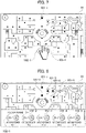
- step S7 When the operation-invalid positions are not operated in step S7 (step S7: NO) and the group display button 103-1 is operated on the air conditioner management screen as illustrated in Fig. 7 (step S8: YES), the display information generator 23 identifies all the air conditioners 10-1 to 10-5 in the store A group to which the air conditioner 10-1 belongs based on the information stored in the device classification information storage 22.
- the display information generator 23 updates the display information such that the display size of the air conditioner icons 101-1 to 101-5 corresponding to the identified air conditioners 10-1 to 10-5 is changed to the second display size "large” that is larger than the first display size, the lighting up of the region around the air conditioner icon 101-1 is terminated, the operation buttons 102-1 to 102-5 for implementing the settings of the corresponding air conditioners 10-1 to 10-5 are displayed at the bottom of the air conditioner management screen, and the display size of the air conditioner icons 101-6 to 101-n corresponding to the air conditioners 10-6 to 10-n in the groups other than the store A group is changed to a third display size "small” that is smaller than the first display size.
- the updated air conditioner management screen is displayed on the touch panel 21 by the display 212 as illustrated in Fig. 8 , for example (step S9).
- step S10 When the manager operates any of the operation buttons, for example, the operation button 102-2 to perform an operation with respect to the operations and settings of the air conditioner 10-2 on the displayed air conditioner management screen (step S10: YES), the operation is detected by the operation detector 211 and the corresponding control information is generated by the control information generator 25. The generated control information is transmitted from the communicator 24 to the air conditioner 10-2, and the corresponding control is performed (step S11).
- the manager When the manager performs a touch operation of any of the air conditioner icons displayed at the second display size "large", for example, the air conditioner icon 101-1 on the displayed air conditioner management screen as illustrated in Fig. 9 , the corresponding operation button 102-1 is highlighted by lighting up the region therearound (step S13).
- the manager can know the position of the operation button for performing an operation with respect to the operations and settings of the air conditioner located at the desired position in the floor configuration diagram.
- step S14 When the manager performs an operation on an operation-invalid position described below on the displayed air conditioner management screen (step S14: YES), the display information generator 23 updates the display information such that the screen is returned to the immediately preceding screen, that is, the screen on which only the air conditioner icon 101-1 is displayed at the second display size "large” and highlighted by lighting up the region therearound and only the operation button 102-1 of the air conditioner 10-1 is displayed at the bottom of the screen. Then, the generated display information of the display information generator 23 is displayed on the touch panel 21 (step S15) and the processing returns to step S5.
- the display information generator 23 determines that operations for the air conditioner icons 101-1 to 101-5 displayed at the second display size "large” and operations for all the displayed operation buttons 102-1 to 102-5 are valid, and determines that operations for the positions other than the aforementioned positions, for example, operations for the air conditioner icons 101-6 to 101-n displayed at the third display size "small" are invalid.
- the manager can know how the air conditioners in the building are classified and performs operations on the air conditioner management screen displayed on the touch panel.
- the manager can know the air conditioner(s) for which a power off operation has not been performed and can perform a power-off operation therefor with an easy operation by displaying the operation buttons of the air conditioners in the store after the prescribed store closing time.
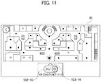
- the air conditioner icon 101-10 illustrated in Fig. 10 when an air conditioner icon displayed at the bottom of the air conditioner management screen, for example, the air conditioner icon 101-10 illustrated in Fig. 10 , is operated in step S3, and the operation button 102-10 and the group display button 103-10 are displayed at the bottom of the screen in a superimposed manner, the air conditioner icon 101-10 may be hidden by the display of the buttons in a superimposed manner and thus may not be visible.
- the portion corresponding to the floor configuration diagram may be displaced to the upper side of the screen such that the operated air conditioner icon 101-10 can be reliably displayed on the screen even when the operation button 102-10 and the group display button 103-10 are displayed.
- the group display button 103 is operated in step S8 and the operation buttons corresponding to the group are displayed, when any of the air conditioner icons displayed at the second display size "large" may be hidden by the display of the buttons in a superimposed manner, the portion corresponding to the floor configuration diagram may be similarly displaced to the upper side of the screen.
- the equipment management apparatus is a controller which manages these air conditioners
- the equipment management screen is an air conditioner management screen.
- the equipment devices are not limited to air conditioners and may be elevators, lights, machine tools, and combinations thereof, for example.
- the equipment management screen may be any screen as long as, in the screen, equipment device icons indicating the respective equipment devices to be managed are superimposed on a floor configuration diagram (floor layout diagram) of a building at positions corresponding to the installation sites of the respective equipment devices.
- the equipment management apparatus is not limited to a controller and may be a communication device with a touch screen such as the tablet terminal 50-3 and the personal computer 50-4.
Landscapes
- Engineering & Computer Science (AREA)
- Theoretical Computer Science (AREA)
- General Engineering & Computer Science (AREA)
- General Physics & Mathematics (AREA)
- Physics & Mathematics (AREA)
- Human Computer Interaction (AREA)
- Combustion & Propulsion (AREA)
- Mechanical Engineering (AREA)
- Chemical & Material Sciences (AREA)
- Computer Networks & Wireless Communication (AREA)
- Air Conditioning Control Device (AREA)
- User Interface Of Digital Computer (AREA)
- Testing And Monitoring For Control Systems (AREA)
- Selective Calling Equipment (AREA)
- Telephonic Communication Services (AREA)
- Alarm Systems (AREA)
Abstract
Description
- Embodiments of the present invention relate to an equipment management apparatus and an equipment management screen generating method.
- A lot of equipment devices are usually installed in large buildings such as commercial facilities and office buildings, and those equipment devices are managed centrally by a central management apparatus which is an equipment management apparatus. The central management apparatus sequentially obtains and stores operating state information from the respective equipment devices.
- A manager is able to perform operations of monitoring the operating state information of the equipment devices and changing setting information, using the central management apparatus. In order to perform these operations, a manager displays an equipment management screen which uses a floor configuration diagram in a building, on a liquid crystal display of the central management apparatus. In the equipment management screen, icons indicating the equipment devices are superimposed on the floor configuration diagram at the positions corresponding to the installation sites of the equipment devices. By specifying the icon of the desired equipment device on the equipment management screen, the operating state information of the desired equipment device is displayed. A manager is able to perform management work for the equipment devices by confirming the operating state information and changing the setting information with respect to the displayed equipment device. The central management apparatus also may be capable of communicating with an operation terminal with which the manager of the equipment devices performs equipment management, and the operation terminal may be used as an equipment management apparatus by allowing the operation terminal to perform displays and operations similar to the central management apparatus on a screen of the operation terminal.
- Patent Literature 1:
Japanese Unexamined Patent Application Publication No. 2009-134469 - Equipment management apparatuses such as the equipment management apparatus described above sometimes manage equipment devices by a group such as stores in a building or offices. At that time, there is a problem that the manager cannot recognize how the equipment devices are grouped from the equipment management screen which uses a floor configuration diagram and thus the manager sometimes faces difficulties in performing operations by group.
- The present invention has been created in view of the above circumstances and aims to provide an equipment management apparatus and an equipment management screen generating method capable of improving the operability of management operations of equipment devices in a large building on a touch panel.
- To achieve the above object, an equipment management apparatus according to the present invention includes: a display configured to display an equipment management screen in which icons indicating equipment devices and having a first display size are superimposed on a floor configuration diagram of a building at positions corresponding to installation sites of the equipment devices; an operation detector configured to detect an operation on the equipment management screen displayed on the display; a device classification information storage configured to store device classification information in which the equipment devices are classified into groups; and a display information generator configured to, upon detection by the operation detector of an operation of one of icons indicating the equipment devices on the equipment management screen displayed on the display, change a display size of the operated icon from a first display size to a second display size larger than the first display size, and display an operation button for implementing settings of the equipment device at a prescribed position on the equipment management screen in a superimposed manner, and upon detection by the operation detector of an operation of specifying display of a group to which the equipment device corresponding to the operated icon belongs, identify all equipment devices belonging to the specified group based on the device classification information stored in the device classification information storage, change display sizes of icons corresponding to the identified equipment devices to the second display size, display operation buttons for implementing settings of the identified equipment devices at prescribed positions on the equipment management screen in a superimposed manner, and change display sizes of icons corresponding to equipment devices not belonging to the specified group to a third display size smaller than the first display size.
- An equipment management screen generating method according to the present invention is performed by an equipment management apparatus including: a display configured to display an equipment management screen in which icons indicating equipment devices and having a first display size are superimposed on a floor configuration diagram of a building at positions corresponding to installation sites of the equipment devices; an operation detector configured to detect an operation on the equipment management screen displayed on the display; and a device classification information storage configured to store device classification information in which the equipment devices are classified into groups, the method comprising: upon detection by the operation detector of an operation of one of icons indicating the equipment devices on the equipment management screen displayed on the display, changing a display size of the operated icon from a first display size to a second display size larger than the first display size, and displaying an operation button for implementing settings of the equipment device at a prescribed position on the equipment management screen in a superimposed manner; and upon detection by the operation detector of an operation of specifying display of a group to which the equipment device corresponding to the operated icon belongs, identifying all equipment devices belonging to the specified group based on the device classification information stored in the device classification information storage, changing display sizes of icons corresponding to the identified equipment devices to the second display size, display operation buttons for implementing settings of the identified equipment devices at prescribed positions on the equipment management screen in a superimposed manner, and changing display sizes of icons corresponding to equipment devices not belonging to the specified group to a third display size smaller than the first display size.
-
-
Fig. 1 is an overall view of a configuration of an air conditioning system using an equipment management apparatus according to an embodiment of the present invention. -
Fig. 2 is a block diagram of a configuration of a controller serving as the equipment management apparatus according to the embodiment of the present invention. -
Fig. 3 illustrates an example of device classification information stored in the controller serving as the equipment management apparatus according to the embodiment of the present invention. -
Fig. 4A is a flowchart of operations performed by the controller serving as the equipment management apparatus according to the embodiment of the present invention. -
Fig. 4B is a flowchart of operations performed by the controller serving as the equipment management apparatus according to the embodiment of the present invention. -
Fig. 5 is a screen configuration diagram of a base air conditioner management screen displayed on a touch panel of the controller serving as the equipment management apparatus according to the embodiment of the present invention. -
Fig. 6 is a screen configuration diagram in a state where an air conditioner icon having a first display size has been operated on an air conditioner management screen displayed on the touch panel of the controller serving as the equipment management apparatus according to the embodiment of the present invention. -
Fig. 7 is a screen configuration diagram in a state where a group display button of a desired air conditioner has been operated on the air conditioner management screen displayed on the touch panel of the controller serving as the equipment management apparatus according to the embodiment of the present invention. -
Fig. 8 is a screen configuration diagram in a state where operation buttons of a prescribed group are displayed on the air conditioner management screen displayed on the touch panel of the controller serving as the equipment management apparatus according to the embodiment of the present invention. -
Fig. 9 is a screen configuration diagram in a state where an air conditioner icon having a second display size has been operated on the air conditioner management screen displayed on the touch panel of the controller serving as the equipment management apparatus according to the embodiment of the present invention. -
Fig. 10 is a screen configuration diagram in a state where an air conditioner icon displayed at the bottom of the screen has been operated on the air conditioner management screen displayed on the touch panel of the controller serving as the equipment management apparatus according to the embodiment of the present invention. -
Fig. 11 is a screen configuration diagram in a state where an operation button is displayed after the air conditioner icon displayed at the bottom of the screen has been operated on the air conditioner management screen displayed on the touch panel of the controller serving as the equipment management apparatus according to the embodiment of the present invention. - A description will be hereinbelow provided for an air conditioning system according to embodiments of a communication system of the present invention by referring to the drawings.
- As an equipment management apparatus according to an embodiment of the present invention, a description will be provided for the configuration of an air conditioning system using a controller as a central management apparatus and a tablet terminal, by referring to
Fig. 1 . Anair conditioning system 1 according to the embodiment includes: air conditioners 10-1 to 10-n installed in a building; acontroller 20 serving as a central management apparatus connected to the air conditioners 10-1 to 10-n; wireless communication access points 40-1 to 40-n connected to thecontroller 20 via ahub 30; a tablet terminal 50-1 wirelessly connected to the access point 40-1; a tablet terminal 50-2 wirelessly connected to the access point 40-2; a tablet terminal 50-3 wirelessly connected to the access point 40-3; and a personal computer 50-4 wirelessly connected to the access point 40-4. Thecontroller 20, the tablet terminals 50-1 to 50-3, and the personal computer 50-4 are operated by a manager of theair conditioning system 1. In the air conditioning system, the air conditioners 10-1 to 10-n installed in the building correspond to equipment devices. - As illustrated in
Fig. 2 , thecontroller 20 includes: atouch panel 21 with a liquid crystal display screen, a deviceclassification information storage 22, adisplay information generator 23, acommunicator 24, and acontrol information generator 25. - The
touch panel 21 includes anoperation detector 211 and adisplay 212. Theoperation detector 211 detects a touch operation by the manager. Thedisplay 212 displays display information provided to the manager. - The device
classification information storage 22 stores device classification information in which the air conditioners 10-1 to 10-n are classified into groups. Thedisplay information generator 23 generates, as the display information, a management screen of the air conditioners 10-1 to 10-n and operating state information of a specified air conditioner based on operation information detected by theoperation detector 211. Thecommunicator 24 communicates with the air conditioners 10-1 to 10-n, the tablet terminals 50-1 to 50-3, and the personal computer 50-4. Thecontrol information generator 25 generates operational control information of the air conditioners 10-1 to 10-n based on the operation information detected by theoperation detector 211. - The tablet terminals 50-1 to 50-3 and the personal computer 50-4 transmit the operational control information for operational control to the air conditioners 10-1 to 10-n as required, and obtains and displays the operating state information of the air conditioners 10-1 to 10-n, through communication with the air conditioners 10-1 to 10-n via the
controller 20. - Next, operations of the
air conditioning system 1 according to the embodiment will be described. Theair conditioning system 1 is installed in a large commercial facility. In theair conditioning system 1, the operational control information for controlling operations of the air conditioners 10-1 to 10-n is transmitted as required and the operating state information of the air conditioners 10-1 to 10-n is obtained and stored at prescribed time intervals by thecontroller 20. - Information in which the air conditioners 10-1 to 10-n are classified depending on the installation sites thereof into groups by stores or predetermined areas (such as a store A, a store B, a store C, a first floor center aisle area, and a first floor west aisle area) in the commercial facility equipped with the
air conditioning system 1 is stored as the device classification information in the deviceclassification information storage 22 of thecontroller 20. - An example of the device classification information is illustrated in
Fig. 3 . In the device classification information illustrated inFig. 3 , the air conditioners 10-1 to 10-5 correspond to a group indicating the air conditioners installed in a store A (a store A group), the air conditioners 10-6 to 10-10 correspond to a group indicating the air conditioners installed in a store B (a store B group), the air conditioners 10-11 to 10-15 correspond to a group indicating the air conditioners installed in a store C (a store C group), the air conditioners 10-16 to 10-18 correspond to a group indicating the air conditioners installed in a first floor center aisle area (a first floor center aisle area group), and the air conditioners 10-19 to 10-21 correspond to a group indicating the air conditioners installed in a first floor west aisle area (a first floor west aisle area group). - The processing performed by the
controller 20 when the manager of the air conditioners 10-1 to 10-n performs operations for management work for the air conditioners 10-1 to 10-n using thecontroller 20 will be described by referring to the flowchart ofFigs. 4A and4B . - First, when the manager performs an operation of displaying the management screen of the air conditioners 10-1 to 10-n on the
touch panel 21 of the controller 20 (step S1: YES), operation information is detected by theoperation detector 211 and obtained by thedisplay information generator 23. Thedisplay information generator 23 generates a base air conditioner management screen as a corresponding equipment management screen. In the base air conditioner management screen, air conditioner icons 101-1 to 101-n indicating the respective air conditioners and having a first display size "medium" are superimposed on a floor configuration diagram (floor layout diagram) of the building at positions corresponding to the installation sites of the respective air conditioners 10-1 to 10-n. The generated air conditioner management screen is displayed on thetouch panel 21 by thedisplay 212 as illustrated inFig. 5 , for example (step S2). In the air conditioner management screen illustrated inFig. 5 , the air conditioner icons that are solid black circles indicate power-on states of thecorresponding air conditioners 10, and the air conditioner icons that are white circles indicate power-off states of thecorresponding air conditioners 10. - When the manager performs a touch operation of any of the air conditioner icons, for example, the air conditioner icon 101-1 corresponding to the air conditioner 10-1 on the base air conditioner management screen displayed on the touch panel 21 (step S3: YES), operation information is detected by the
operation detector 211 and obtained by thedisplay information generator 23. - Upon obtaining information indicating detection of the touch operation of the air conditioner icon 101-1 on the
touch panel 21, thedisplay information generator 23 updates the display information such that the display size of the air conditioner icon 101-1 displayed on the air conditioner management screen is changed to a second display size "large" that is larger than the first display size, the air conditioner icon 101-1 is highlighted by lighting up the region therearound, and an operation button 102-1 for implementing operations and settings of the corresponding air conditioner 10-1 and a group display button 103-1 for instructing display of the group to which the air conditioner 10-1 belongs are displayed at the bottom of the air conditioner management screen in a superimposed manner. In the operation button 102-1, the current operating state (power-on state / power-off state) of the corresponding air conditioner 10-1 and setting information (set temperature or the like) are displayed. The generated display information of the air conditioner management screen is displayed on thetouch panel 21 by thedisplay 212 as illustrated inFig. 6 , for example (step S4). - When the manager performs an operation with respect to the operations and settings of the corresponding air conditioner 10-1, for example, a power-off operation by means of the operation button 102-1 on the base air conditioner management screen displayed on the touch panel 21 (step S5: YES), the operation is detected by the
operation detector 211 and a power-off instruction for the corresponding air conditioner 10-1 is generated as control information by thecontrol information generator 25. The generated control information is transmitted from thecommunicator 24 to the corresponding air conditioner 10-1, and the power state of the corresponding air conditioner 10-1 is turned to an off state (step S6). - When the manager performs an operation on an operation-invalid position on the air conditioner management screen displayed on the touch panel 21 (step S7: YES), the
display information generator 23 returns the display size of the air conditioner icon 101-1 to the first display size "medium", terminates the lighting up of the region around the air conditioner icon 101-1, terminates the display of the operation button 102-1, and then returns the display of thetouch panel 21 to the base air conditioner management screen by (step S2). Operation-invalid positions on the air conditioner management screen are positions other than the air conditioner icon 101-1 displayed at the second display size "large", the air conditioner icons 101-2 to 101-n displayed at the first display size "medium" other than the air conditioner icon 101-1, the operation button 102-1, and the group display button 103-1. - When the operation-invalid positions are not operated in step S7 (step S7: NO) and the group display button 103-1 is operated on the air conditioner management screen as illustrated in
Fig. 7 (step S8: YES), thedisplay information generator 23 identifies all the air conditioners 10-1 to 10-5 in the store A group to which the air conditioner 10-1 belongs based on the information stored in the deviceclassification information storage 22. - Then, the
display information generator 23 updates the display information such that the display size of the air conditioner icons 101-1 to 101-5 corresponding to the identified air conditioners 10-1 to 10-5 is changed to the second display size "large" that is larger than the first display size, the lighting up of the region around the air conditioner icon 101-1 is terminated, the operation buttons 102-1 to 102-5 for implementing the settings of the corresponding air conditioners 10-1 to 10-5 are displayed at the bottom of the air conditioner management screen, and the display size of the air conditioner icons 101-6 to 101-n corresponding to the air conditioners 10-6 to 10-n in the groups other than the store A group is changed to a third display size "small" that is smaller than the first display size. The updated air conditioner management screen is displayed on thetouch panel 21 by thedisplay 212 as illustrated inFig. 8 , for example (step S9). - When the manager operates any of the operation buttons, for example, the operation button 102-2 to perform an operation with respect to the operations and settings of the air conditioner 10-2 on the displayed air conditioner management screen (step S10: YES), the operation is detected by the
operation detector 211 and the corresponding control information is generated by thecontrol information generator 25. The generated control information is transmitted from thecommunicator 24 to the air conditioner 10-2, and the corresponding control is performed (step S11). - When the manager performs a touch operation of any of the air conditioner icons displayed at the second display size "large", for example, the air conditioner icon 101-1 on the displayed air conditioner management screen as illustrated in
Fig. 9 , the corresponding operation button 102-1 is highlighted by lighting up the region therearound (step S13). Thus, the manager can know the position of the operation button for performing an operation with respect to the operations and settings of the air conditioner located at the desired position in the floor configuration diagram. - When the manager performs an operation on an operation-invalid position described below on the displayed air conditioner management screen (step S14: YES), the
display information generator 23 updates the display information such that the screen is returned to the immediately preceding screen, that is, the screen on which only the air conditioner icon 101-1 is displayed at the second display size "large" and highlighted by lighting up the region therearound and only the operation button 102-1 of the air conditioner 10-1 is displayed at the bottom of the screen. Then, the generated display information of thedisplay information generator 23 is displayed on the touch panel 21 (step S15) and the processing returns to step S5. - In the air conditioner management screen displayed in step S9, the
display information generator 23 determines that operations for the air conditioner icons 101-1 to 101-5 displayed at the second display size "large" and operations for all the displayed operation buttons 102-1 to 102-5 are valid, and determines that operations for the positions other than the aforementioned positions, for example, operations for the air conditioner icons 101-6 to 101-n displayed at the third display size "small" are invalid. - According to the embodiment above, the manager can know how the air conditioners in the building are classified and performs operations on the air conditioner management screen displayed on the touch panel. Thus, in a case where it is agreed that all the air conditioners in a prescribed store in the building are to be turned to a power-off state at a prescribed store closing time every day, the manager can know the air conditioner(s) for which a power off operation has not been performed and can perform a power-off operation therefor with an easy operation by displaying the operation buttons of the air conditioners in the store after the prescribed store closing time.
- In the embodiment above, when an air conditioner icon displayed at the bottom of the air conditioner management screen, for example, the air conditioner icon 101-10 illustrated in
Fig. 10 , is operated in step S3, and the operation button 102-10 and the group display button 103-10 are displayed at the bottom of the screen in a superimposed manner, the air conditioner icon 101-10 may be hidden by the display of the buttons in a superimposed manner and thus may not be visible. In this case, as illustrated inFig. 11 , the portion corresponding to the floor configuration diagram may be displaced to the upper side of the screen such that the operated air conditioner icon 101-10 can be reliably displayed on the screen even when the operation button 102-10 and the group display button 103-10 are displayed. Also in a case where the group display button 103 is operated in step S8 and the operation buttons corresponding to the group are displayed, when any of the air conditioner icons displayed at the second display size "large" may be hidden by the display of the buttons in a superimposed manner, the portion corresponding to the floor configuration diagram may be similarly displaced to the upper side of the screen. - In the embodiment, an example is described in which the equipment devices are air conditioners, the equipment management apparatus is a controller which manages these air conditioners, and the equipment management screen is an air conditioner management screen. However, the equipment devices are not limited to air conditioners and may be elevators, lights, machine tools, and combinations thereof, for example. The equipment management screen may be any screen as long as, in the screen, equipment device icons indicating the respective equipment devices to be managed are superimposed on a floor configuration diagram (floor layout diagram) of a building at positions corresponding to the installation sites of the respective equipment devices. The equipment management apparatus is not limited to a controller and may be a communication device with a touch screen such as the tablet terminal 50-3 and the personal computer 50-4.
- While certain embodiments have been described, these embodiments have been presented by way of example only, and are not intended to limit the scope of the inventions. Indeed, the novel embodiments described herein may be embodied in a variety of other forms; furthermore, various omissions, substitutions and changes in the form of the embodiments described herein may be made without departing from the spirit of the inventions. The accompanying claims and their equivalents are intended to cover such forms or modifications as would fall within the scope and spirit of the inventions.
Claims (5)
- An equipment management apparatus comprising:a display configured to display an equipment management screen in which icons indicating equipment devices and having a first display size are superimposed on a floor configuration diagram of a building at positions corresponding to installation sites of the equipment devices;an operation detector configured to detect an operation on the equipment management screen displayed on the display;a device classification information storage configured to store device classification information in which the equipment devices are classified into groups; anda display information generator configured toupon detection by the operation detector of an operation of one of icons indicating the equipment devices on the equipment management screen displayed on the display, change a display size of the operated icon from a first display size to a second display size larger than the first display size, and display an operation button for implementing settings of the equipment device at a prescribed position on the equipment management screen in a superimposed manner, andupon detection by the operation detector of an operation of specifying display of a group to which the equipment device corresponding to the operated icon belongs, identify all equipment devices belonging to the specified group based on the device classification information stored in the device classification information storage, change display sizes of icons corresponding to the identified equipment devices to the second display size, display operation buttons for implementing settings of the identified equipment devices at prescribed positions on the equipment management screen in a superimposed manner, and change display sizes of icons corresponding to equipment devices not belonging to the specified group to a third display size smaller than the first display size.
- The equipment management apparatus according to claim 1, wherein, upon detection by the operation detector of an operation of any of the icons of the equipment devices belonging to the specified group being displayed at the second display size on the equipment management screen displayed on the display, the display information generator configured to highlight the operated operation button.
- The equipment management apparatus according to claim 1 or 2, wherein the display information generator is configured todetermine that operations on the icons displayed on the equipment management screen at the first display size or the second display size and operations on all the displayed operation buttons are valid, and determine that operations on positions other than the icons displayed at the first display size or the second display size and the displayed operation buttons are invalid, andupon an operation determined as invalid being performed during display of the icons corresponding to the equipment devices belonging to the specified group on the equipment management screen, return to a screen displayed prior to specifying display of the specified group.
- The equipment management apparatus according to any one of claims 1 to 3, wherein, upon displaying the operation buttons on the equipment management screen in a superimposed manner, the display information generator is configured to display the equipment management screen to be displaced so as not to hide the icons displayed at the second display size.
- An equipment management screen generating method performed by an equipment management apparatus,the equipment management apparatus comprising:a display configured to display an equipment management screen in which icons indicating equipment devices and having a first display size are superimposed on a floor configuration diagram of a building at positions corresponding to installation sites of the equipment devices;an operation detector configured to detect an operation on the equipment management screen displayed on the display; anda device classification information storage configured to store device classification information in which the equipment devices are classified into groups,the method comprising:upon detection by the operation detector of an operation of one of icons indicating the equipment devices on the equipment management screen displayed on the display, changing a display size of the operated icon from a first display size to a second display size larger than the first display size, and displaying an operation button for implementing settings of the equipment device at a prescribed position on the equipment management screen in a superimposed manner; andupon detection by the operation detector of an operation of specifying display of a group to which the equipment device corresponding to the operated icon belongs, identifying all equipment devices belonging to the specified group based on the device classification information stored in the device classification information storage, changing display sizes of icons corresponding to the identified equipment devices to the second display size, displaying operation buttons for implementing settings of the identified equipment devices at prescribed positions on the equipment management screen in a superimposed manner, and changing display sizes of icons corresponding to equipment devices not belonging to the specified group to a third display size smaller than the first display size.
Applications Claiming Priority (1)
| Application Number | Priority Date | Filing Date | Title |
|---|---|---|---|
| PCT/JP2020/008035 WO2021171484A1 (en) | 2020-02-27 | 2020-02-27 | Equipment management device and method for generating equipment management screen |
Publications (3)
| Publication Number | Publication Date |
|---|---|
| EP4113234A1 true EP4113234A1 (en) | 2023-01-04 |
| EP4113234A4 EP4113234A4 (en) | 2023-11-08 |
| EP4113234B1 EP4113234B1 (en) | 2025-05-21 |
Family
ID=77490054
Family Applications (1)
| Application Number | Title | Priority Date | Filing Date |
|---|---|---|---|
| EP20921201.8A Active EP4113234B1 (en) | 2020-02-27 | 2020-02-27 | Equipment management device and method for generating equipment management screen |
Country Status (6)
| Country | Link |
|---|---|
| US (1) | US11740762B2 (en) |
| EP (1) | EP4113234B1 (en) |
| JP (1) | JP7310005B2 (en) |
| CN (1) | CN115176211B (en) |
| AU (1) | AU2020431710B2 (en) |
| WO (1) | WO2021171484A1 (en) |
Family Cites Families (21)
| Publication number | Priority date | Publication date | Assignee | Title |
|---|---|---|---|---|
| JP4195676B2 (en) * | 2004-04-20 | 2008-12-10 | 三菱重工業株式会社 | Air conditioning monitoring device and building management system |
| JP2008191879A (en) * | 2007-02-02 | 2008-08-21 | Sharp Corp | INFORMATION DISPLAY DEVICE, INFORMATION DISPLAY DEVICE DISPLAY METHOD, INFORMATION DISPLAY PROGRAM, AND RECORDING MEDIUM CONTAINING INFORMATION DISPLAY PROGRAM |
| JP2009134469A (en) * | 2007-11-29 | 2009-06-18 | Daikin Ind Ltd | Device management system and device management program |
| US8819560B2 (en) * | 2008-08-04 | 2014-08-26 | International Business Machines Corporation | Dispatching events to multiple browser windows/tabs using a single connection |
| TWI489067B (en) * | 2010-02-10 | 2015-06-21 | Hitachi Appliances Inc | Air conditioning management system |
| EP2607804B1 (en) * | 2010-08-18 | 2019-08-28 | Mitsubishi Electric Corporation | Air conditioning control device, air conditioning control method and program |
| WO2012101272A1 (en) * | 2011-01-28 | 2012-08-02 | Flir Systems Ab | A method for managing ir image data |
| CN102855070B (en) | 2011-06-30 | 2015-08-26 | 联想(北京)有限公司 | A kind of method of managing electronic device display screen and electronic equipment |
| JP6058025B2 (en) * | 2012-12-05 | 2017-01-11 | 吉田 健治 | Control interface to facility management system |
| EP2961187B1 (en) * | 2013-02-20 | 2018-10-03 | Panasonic Intellectual Property Corporation of America | Method for controlling information apparatus and program |
| SG2014010086A (en) * | 2013-02-20 | 2015-02-27 | Panasonic Ip Corp America | Control method for information apparatus and program |
| KR102152643B1 (en) * | 2013-07-04 | 2020-09-08 | 엘지이노텍 주식회사 | The light system using the mobile device |
| JP6249702B2 (en) * | 2013-09-26 | 2017-12-20 | 東芝キヤリア株式会社 | Air conditioner management system |
| WO2015111288A1 (en) * | 2014-01-21 | 2015-07-30 | 東芝キヤリア株式会社 | Air conditioner management device |
| JP2016018397A (en) * | 2014-07-08 | 2016-02-01 | 三菱電機株式会社 | Device management apparatus, device management method, and display device |
| US10262466B2 (en) | 2015-10-14 | 2019-04-16 | Qualcomm Incorporated | Systems and methods for adjusting a combined image visualization based on depth information |
| JP6637733B2 (en) * | 2015-11-12 | 2020-01-29 | 東芝キヤリア株式会社 | Air conditioner management screen generation device, air conditioning management device using the same, and air conditioner management screen generation method |
| US10241669B2 (en) * | 2017-02-21 | 2019-03-26 | International Business Machines Corporation | Touchscreen device |
| JP7158882B2 (en) * | 2018-04-17 | 2022-10-24 | 立川ブラインド工業株式会社 | Mobile terminal and signal processing device, and remote control system for electric shielding device |
| JP7186517B2 (en) * | 2018-06-05 | 2022-12-09 | 東芝ライフスタイル株式会社 | clothing processing equipment |
| CN109028515A (en) | 2018-07-23 | 2018-12-18 | 广东美的制冷设备有限公司 | Control method, air conditioner and the storage medium of air conditioner |
-
2020
- 2020-02-27 WO PCT/JP2020/008035 patent/WO2021171484A1/en not_active Ceased
- 2020-02-27 CN CN202080097529.3A patent/CN115176211B/en active Active
- 2020-02-27 AU AU2020431710A patent/AU2020431710B2/en active Active
- 2020-02-27 EP EP20921201.8A patent/EP4113234B1/en active Active
- 2020-02-27 JP JP2022502715A patent/JP7310005B2/en active Active
-
2022
- 2022-08-23 US US17/893,497 patent/US11740762B2/en active Active
Also Published As
| Publication number | Publication date |
|---|---|
| US20220404954A1 (en) | 2022-12-22 |
| AU2020431710A1 (en) | 2022-09-29 |
| EP4113234B1 (en) | 2025-05-21 |
| US11740762B2 (en) | 2023-08-29 |
| JP7310005B2 (en) | 2023-07-18 |
| CN115176211A (en) | 2022-10-11 |
| AU2020431710B2 (en) | 2023-07-20 |
| JPWO2021171484A1 (en) | 2021-09-02 |
| CN115176211B (en) | 2025-08-26 |
| EP4113234A4 (en) | 2023-11-08 |
| WO2021171484A1 (en) | 2021-09-02 |
Similar Documents
| Publication | Publication Date | Title |
|---|---|---|
| JP6436722B2 (en) | SETTING DEVICE, LIGHTING SYSTEM, CONTROL PROGRAM, AND SETTING DEVICE OPERATION METHOD | |
| EP3576065B1 (en) | Systems and methods of alarm controls and directed audio evacuation | |
| US20130156434A1 (en) | Remote control system and apparatus | |
| EP3567837B1 (en) | Radio communication system | |
| US10119716B2 (en) | Air-conditioning apparatus controller and air-conditioning system | |
| US9123218B2 (en) | Fire control panel with a display unit for displaying system information | |
| MX2011009772A (en) | SEMIAUTOMATIC METHOD OF REPLACEMENT OF BALASTROS. | |
| US10598400B2 (en) | Remote control device | |
| JP2019205093A (en) | Sensor coordination facility system | |
| US20220014885A1 (en) | Environment control system for controlling environmental conditions in a building | |
| EP4113234B1 (en) | Equipment management device and method for generating equipment management screen | |
| EP3460645B1 (en) | Operation apparatus | |
| WO2012086705A1 (en) | Apparatus management system, and mobile terminal which is used in apparatus management system | |
| US20190179274A1 (en) | Control content management system, power control system, control content management method, and computer-readable recording medium | |
| EP3806481A1 (en) | Equipment management device using touch panel, and method for generating management screen | |
| JP2016018395A (en) | Device management apparatus, device management method, and display device | |
| US11859844B2 (en) | Air conditioner management device, and air conditioner management screen generation method | |
| WO2018131609A1 (en) | Air-conditioning management device and display control method therefor | |
| JP6750429B2 (en) | Operating device and lighting control system | |
| JP2017089993A (en) | Air conditioner management screen generation apparatus, air conditioning management apparatus using the same, and air conditioner management screen generation method | |
| US20230400844A1 (en) | Monitoring apparatus, display method, program, and monitoring system | |
| WO2025197007A1 (en) | Air conditioning communication system, gateway device, and program | |
| JP2024101077A (en) | Display method, information processing system, device management system, and communication method | |
| JP2023082456A (en) | Air conditioner management device |
Legal Events
| Date | Code | Title | Description |
|---|---|---|---|
| STAA | Information on the status of an ep patent application or granted ep patent |
Free format text: STATUS: THE INTERNATIONAL PUBLICATION HAS BEEN MADE |
|
| PUAI | Public reference made under article 153(3) epc to a published international application that has entered the european phase |
Free format text: ORIGINAL CODE: 0009012 |
|
| STAA | Information on the status of an ep patent application or granted ep patent |
Free format text: STATUS: REQUEST FOR EXAMINATION WAS MADE |
|
| 17P | Request for examination filed |
Effective date: 20220923 |
|
| AK | Designated contracting states |
Kind code of ref document: A1 Designated state(s): AL AT BE BG CH CY CZ DE DK EE ES FI FR GB GR HR HU IE IS IT LI LT LU LV MC MK MT NL NO PL PT RO RS SE SI SK SM TR |
|
| DAV | Request for validation of the european patent (deleted) | ||
| DAX | Request for extension of the european patent (deleted) | ||
| A4 | Supplementary search report drawn up and despatched |
Effective date: 20231010 |
|
| RIC1 | Information provided on ipc code assigned before grant |
Ipc: F24F 11/52 20180101ALI20231004BHEP Ipc: H04Q 9/00 20060101ALI20231004BHEP Ipc: H04M 11/00 20060101ALI20231004BHEP Ipc: G05B 23/02 20060101AFI20231004BHEP |
|
| GRAP | Despatch of communication of intention to grant a patent |
Free format text: ORIGINAL CODE: EPIDOSNIGR1 |
|
| STAA | Information on the status of an ep patent application or granted ep patent |
Free format text: STATUS: GRANT OF PATENT IS INTENDED |
|
| INTG | Intention to grant announced |
Effective date: 20241212 |
|
| GRAS | Grant fee paid |
Free format text: ORIGINAL CODE: EPIDOSNIGR3 |
|
| GRAA | (expected) grant |
Free format text: ORIGINAL CODE: 0009210 |
|
| STAA | Information on the status of an ep patent application or granted ep patent |
Free format text: STATUS: THE PATENT HAS BEEN GRANTED |
|
| AK | Designated contracting states |
Kind code of ref document: B1 Designated state(s): AL AT BE BG CH CY CZ DE DK EE ES FI FR GB GR HR HU IE IS IT LI LT LU LV MC MK MT NL NO PL PT RO RS SE SI SK SM TR |
|
| RAP3 | Party data changed (applicant data changed or rights of an application transferred) |
Owner name: CARRIER JAPAN CORPORATION |
|
| REG | Reference to a national code |
Ref country code: GB Ref legal event code: FG4D |
|
| REG | Reference to a national code |
Ref country code: CH Ref legal event code: EP |
|
| REG | Reference to a national code |
Ref country code: DE Ref legal event code: R096 Ref document number: 602020051884 Country of ref document: DE |
|
| REG | Reference to a national code |
Ref country code: IE Ref legal event code: FG4D |
|
| REG | Reference to a national code |
Ref country code: NL Ref legal event code: MP Effective date: 20250521 |
|
| PG25 | Lapsed in a contracting state [announced via postgrant information from national office to epo] |
Ref country code: FI Free format text: LAPSE BECAUSE OF FAILURE TO SUBMIT A TRANSLATION OF THE DESCRIPTION OR TO PAY THE FEE WITHIN THE PRESCRIBED TIME-LIMIT Effective date: 20250521 Ref country code: PT Free format text: LAPSE BECAUSE OF FAILURE TO SUBMIT A TRANSLATION OF THE DESCRIPTION OR TO PAY THE FEE WITHIN THE PRESCRIBED TIME-LIMIT Effective date: 20250922 Ref country code: ES Free format text: LAPSE BECAUSE OF FAILURE TO SUBMIT A TRANSLATION OF THE DESCRIPTION OR TO PAY THE FEE WITHIN THE PRESCRIBED TIME-LIMIT Effective date: 20250521 |
|
| REG | Reference to a national code |
Ref country code: LT Ref legal event code: MG9D |
|
| PG25 | Lapsed in a contracting state [announced via postgrant information from national office to epo] |
Ref country code: GR Free format text: LAPSE BECAUSE OF FAILURE TO SUBMIT A TRANSLATION OF THE DESCRIPTION OR TO PAY THE FEE WITHIN THE PRESCRIBED TIME-LIMIT Effective date: 20250822 Ref country code: NO Free format text: LAPSE BECAUSE OF FAILURE TO SUBMIT A TRANSLATION OF THE DESCRIPTION OR TO PAY THE FEE WITHIN THE PRESCRIBED TIME-LIMIT Effective date: 20250821 |
|
| PG25 | Lapsed in a contracting state [announced via postgrant information from national office to epo] |
Ref country code: NL Free format text: LAPSE BECAUSE OF FAILURE TO SUBMIT A TRANSLATION OF THE DESCRIPTION OR TO PAY THE FEE WITHIN THE PRESCRIBED TIME-LIMIT Effective date: 20250521 Ref country code: PL Free format text: LAPSE BECAUSE OF FAILURE TO SUBMIT A TRANSLATION OF THE DESCRIPTION OR TO PAY THE FEE WITHIN THE PRESCRIBED TIME-LIMIT Effective date: 20250521 |
|
| PG25 | Lapsed in a contracting state [announced via postgrant information from national office to epo] |
Ref country code: BG Free format text: LAPSE BECAUSE OF FAILURE TO SUBMIT A TRANSLATION OF THE DESCRIPTION OR TO PAY THE FEE WITHIN THE PRESCRIBED TIME-LIMIT Effective date: 20250521 |
|
| PG25 | Lapsed in a contracting state [announced via postgrant information from national office to epo] |
Ref country code: HR Free format text: LAPSE BECAUSE OF FAILURE TO SUBMIT A TRANSLATION OF THE DESCRIPTION OR TO PAY THE FEE WITHIN THE PRESCRIBED TIME-LIMIT Effective date: 20250521 |
|
| PG25 | Lapsed in a contracting state [announced via postgrant information from national office to epo] |
Ref country code: RS Free format text: LAPSE BECAUSE OF FAILURE TO SUBMIT A TRANSLATION OF THE DESCRIPTION OR TO PAY THE FEE WITHIN THE PRESCRIBED TIME-LIMIT Effective date: 20250821 |
|
| PG25 | Lapsed in a contracting state [announced via postgrant information from national office to epo] |
Ref country code: IS Free format text: LAPSE BECAUSE OF FAILURE TO SUBMIT A TRANSLATION OF THE DESCRIPTION OR TO PAY THE FEE WITHIN THE PRESCRIBED TIME-LIMIT Effective date: 20250921 |
|
| PG25 | Lapsed in a contracting state [announced via postgrant information from national office to epo] |
Ref country code: LV Free format text: LAPSE BECAUSE OF FAILURE TO SUBMIT A TRANSLATION OF THE DESCRIPTION OR TO PAY THE FEE WITHIN THE PRESCRIBED TIME-LIMIT Effective date: 20250521 |
|
| REG | Reference to a national code |
Ref country code: AT Ref legal event code: MK05 Ref document number: 1797263 Country of ref document: AT Kind code of ref document: T Effective date: 20250521 |
|
| PG25 | Lapsed in a contracting state [announced via postgrant information from national office to epo] |
Ref country code: AT Free format text: LAPSE BECAUSE OF FAILURE TO SUBMIT A TRANSLATION OF THE DESCRIPTION OR TO PAY THE FEE WITHIN THE PRESCRIBED TIME-LIMIT Effective date: 20250521 Ref country code: SM Free format text: LAPSE BECAUSE OF FAILURE TO SUBMIT A TRANSLATION OF THE DESCRIPTION OR TO PAY THE FEE WITHIN THE PRESCRIBED TIME-LIMIT Effective date: 20250521 Ref country code: DK Free format text: LAPSE BECAUSE OF FAILURE TO SUBMIT A TRANSLATION OF THE DESCRIPTION OR TO PAY THE FEE WITHIN THE PRESCRIBED TIME-LIMIT Effective date: 20250521 |
|
| PG25 | Lapsed in a contracting state [announced via postgrant information from national office to epo] |
Ref country code: CZ Free format text: LAPSE BECAUSE OF FAILURE TO SUBMIT A TRANSLATION OF THE DESCRIPTION OR TO PAY THE FEE WITHIN THE PRESCRIBED TIME-LIMIT Effective date: 20250521 |
|
| PG25 | Lapsed in a contracting state [announced via postgrant information from national office to epo] |
Ref country code: EE Free format text: LAPSE BECAUSE OF FAILURE TO SUBMIT A TRANSLATION OF THE DESCRIPTION OR TO PAY THE FEE WITHIN THE PRESCRIBED TIME-LIMIT Effective date: 20250521 |
|
| PG25 | Lapsed in a contracting state [announced via postgrant information from national office to epo] |
Ref country code: SK Free format text: LAPSE BECAUSE OF FAILURE TO SUBMIT A TRANSLATION OF THE DESCRIPTION OR TO PAY THE FEE WITHIN THE PRESCRIBED TIME-LIMIT Effective date: 20250521 |
|
| PG25 | Lapsed in a contracting state [announced via postgrant information from national office to epo] |
Ref country code: IT Free format text: LAPSE BECAUSE OF FAILURE TO SUBMIT A TRANSLATION OF THE DESCRIPTION OR TO PAY THE FEE WITHIN THE PRESCRIBED TIME-LIMIT Effective date: 20250521 |
|
| REG | Reference to a national code |
Ref country code: DE Ref legal event code: R097 Ref document number: 602020051884 Country of ref document: DE |
|
| PLBE | No opposition filed within time limit |
Free format text: ORIGINAL CODE: 0009261 |
|
| STAA | Information on the status of an ep patent application or granted ep patent |
Free format text: STATUS: NO OPPOSITION FILED WITHIN TIME LIMIT |
|
| REG | Reference to a national code |
Ref country code: CH Ref legal event code: L10 Free format text: ST27 STATUS EVENT CODE: U-0-0-L10-L00 (AS PROVIDED BY THE NATIONAL OFFICE) Effective date: 20260402 |
|
| PGFP | Annual fee paid to national office [announced via postgrant information from national office to epo] |
Ref country code: GB Payment date: 20260121 Year of fee payment: 7 |
|
| PGFP | Annual fee paid to national office [announced via postgrant information from national office to epo] |
Ref country code: DE Payment date: 20260121 Year of fee payment: 7 |
|
| PGFP | Annual fee paid to national office [announced via postgrant information from national office to epo] |
Ref country code: FR Payment date: 20260121 Year of fee payment: 7 |
|
| 26N | No opposition filed |
Effective date: 20260224 |