EP4113143A1 - Device and method for diagnosing failure of inverter initial charging circuit - Google Patents
Device and method for diagnosing failure of inverter initial charging circuit Download PDFInfo
- Publication number
- EP4113143A1 EP4113143A1 EP21761792.7A EP21761792A EP4113143A1 EP 4113143 A1 EP4113143 A1 EP 4113143A1 EP 21761792 A EP21761792 A EP 21761792A EP 4113143 A1 EP4113143 A1 EP 4113143A1
- Authority
- EP
- European Patent Office
- Prior art keywords
- initial charging
- resistor
- voltage
- inverter
- relay
- Prior art date
- Legal status (The legal status is an assumption and is not a legal conclusion. Google has not performed a legal analysis and makes no representation as to the accuracy of the status listed.)
- Pending
Links
Images




Classifications
-
- H—ELECTRICITY
- H02—GENERATION; CONVERSION OR DISTRIBUTION OF ELECTRIC POWER
- H02M—APPARATUS FOR CONVERSION BETWEEN AC AND AC, BETWEEN AC AND DC, OR BETWEEN DC AND DC, AND FOR USE WITH MAINS OR SIMILAR POWER SUPPLY SYSTEMS; CONVERSION OF DC OR AC INPUT POWER INTO SURGE OUTPUT POWER; CONTROL OR REGULATION THEREOF
- H02M1/00—Details of apparatus for conversion
- H02M1/36—Means for starting or stopping converters
-
- G—PHYSICS
- G01—MEASURING; TESTING
- G01R—MEASURING ELECTRIC VARIABLES; MEASURING MAGNETIC VARIABLES
- G01R31/00—Arrangements for testing electric properties; Arrangements for locating electric faults; Arrangements for electrical testing characterised by what is being tested not provided for elsewhere
- G01R31/40—Testing power supplies
-
- G—PHYSICS
- G01—MEASURING; TESTING
- G01R—MEASURING ELECTRIC VARIABLES; MEASURING MAGNETIC VARIABLES
- G01R1/00—Details of instruments or arrangements of the types included in groups G01R5/00 - G01R13/00 and G01R31/00
- G01R1/20—Modifications of basic electric elements for use in electric measuring instruments; Structural combinations of such elements with such instruments
- G01R1/203—Resistors used for electric measuring, e.g. decade resistors standards, resistors for comparators, series resistors, shunts
-
- G—PHYSICS
- G01—MEASURING; TESTING
- G01R—MEASURING ELECTRIC VARIABLES; MEASURING MAGNETIC VARIABLES
- G01R31/00—Arrangements for testing electric properties; Arrangements for locating electric faults; Arrangements for electrical testing characterised by what is being tested not provided for elsewhere
- G01R31/327—Testing of circuit interrupters, switches or circuit-breakers
- G01R31/3277—Testing of circuit interrupters, switches or circuit-breakers of low voltage devices, e.g. domestic or industrial devices, such as motor protections, relays, rotation switches
- G01R31/3278—Testing of circuit interrupters, switches or circuit-breakers of low voltage devices, e.g. domestic or industrial devices, such as motor protections, relays, rotation switches of relays, solenoids or reed switches
-
- H—ELECTRICITY
- H02—GENERATION; CONVERSION OR DISTRIBUTION OF ELECTRIC POWER
- H02M—APPARATUS FOR CONVERSION BETWEEN AC AND AC, BETWEEN AC AND DC, OR BETWEEN DC AND DC, AND FOR USE WITH MAINS OR SIMILAR POWER SUPPLY SYSTEMS; CONVERSION OF DC OR AC INPUT POWER INTO SURGE OUTPUT POWER; CONTROL OR REGULATION THEREOF
- H02M1/00—Details of apparatus for conversion
- H02M1/32—Means for protecting converters other than automatic disconnection
-
- H—ELECTRICITY
- H02—GENERATION; CONVERSION OR DISTRIBUTION OF ELECTRIC POWER
- H02M—APPARATUS FOR CONVERSION BETWEEN AC AND AC, BETWEEN AC AND DC, OR BETWEEN DC AND DC, AND FOR USE WITH MAINS OR SIMILAR POWER SUPPLY SYSTEMS; CONVERSION OF DC OR AC INPUT POWER INTO SURGE OUTPUT POWER; CONTROL OR REGULATION THEREOF
- H02M5/00—Conversion of AC power input into AC power output, e.g. for change of voltage, for change of frequency, for change of number of phases
- H02M5/40—Conversion of AC power input into AC power output, e.g. for change of voltage, for change of frequency, for change of number of phases with intermediate conversion into DC
- H02M5/42—Conversion of AC power input into AC power output, e.g. for change of voltage, for change of frequency, for change of number of phases with intermediate conversion into DC by static converters
- H02M5/44—Conversion of AC power input into AC power output, e.g. for change of voltage, for change of frequency, for change of number of phases with intermediate conversion into DC by static converters using discharge tubes or semiconductor devices to convert the intermediate DC into AC
- H02M5/453—Conversion of AC power input into AC power output, e.g. for change of voltage, for change of frequency, for change of number of phases with intermediate conversion into DC by static converters using discharge tubes or semiconductor devices to convert the intermediate DC into AC using devices of a triode or transistor type requiring continuous application of a control signal
- H02M5/458—Conversion of AC power input into AC power output, e.g. for change of voltage, for change of frequency, for change of number of phases with intermediate conversion into DC by static converters using discharge tubes or semiconductor devices to convert the intermediate DC into AC using devices of a triode or transistor type requiring continuous application of a control signal using semiconductor devices only
-
- G—PHYSICS
- G01—MEASURING; TESTING
- G01R—MEASURING ELECTRIC VARIABLES; MEASURING MAGNETIC VARIABLES
- G01R31/00—Arrangements for testing electric properties; Arrangements for locating electric faults; Arrangements for electrical testing characterised by what is being tested not provided for elsewhere
- G01R31/327—Testing of circuit interrupters, switches or circuit-breakers
- G01R31/3271—Testing of circuit interrupters, switches or circuit-breakers of high voltage or medium voltage devices
- G01R31/3275—Fault detection or status indication
-
- G—PHYSICS
- G01—MEASURING; TESTING
- G01R—MEASURING ELECTRIC VARIABLES; MEASURING MAGNETIC VARIABLES
- G01R31/00—Arrangements for testing electric properties; Arrangements for locating electric faults; Arrangements for electrical testing characterised by what is being tested not provided for elsewhere
- G01R31/40—Testing power supplies
- G01R31/42—AC power supplies
-
- H—ELECTRICITY
- H02—GENERATION; CONVERSION OR DISTRIBUTION OF ELECTRIC POWER
- H02M—APPARATUS FOR CONVERSION BETWEEN AC AND AC, BETWEEN AC AND DC, OR BETWEEN DC AND DC, AND FOR USE WITH MAINS OR SIMILAR POWER SUPPLY SYSTEMS; CONVERSION OF DC OR AC INPUT POWER INTO SURGE OUTPUT POWER; CONTROL OR REGULATION THEREOF
- H02M1/00—Details of apparatus for conversion
- H02M1/44—Circuits or arrangements for compensating for electromagnetic interference in converters or inverters
Definitions
- the present invention relates to an inverter, and more particularly to an initial charging circuit of an inverter.
- the inverter is one of the representative power conversion devices along with the converter.
- the inverter receives AC power, converts it to DC and then converts it back to AC for controlling an electric motor to control the electric motor. It is used in various forms throughout the industry where electric motors are used, such as fans, pumps, elevators, transfer devices, production lines and the like.
- the converter is a device that converts AC or DC input power into DC, and the power conversion method is similar to that of an inverter, and similar to an inverter, it is used variously throughout the industry.
- An initial charging circuit is essential for an inverter.
- the initial charging circuit prevents an overcurrent from flowing in the DC link capacitor of the inverter due to the inrush current, and protects the devices from the parasitic inductance components of a rectifier and a DC terminal and the high voltage generated by the inrush current.
- FIG. 1 shows the structure of a general inverter according to prior art.
- the rectifier 10 converts three-phase AC power into DC power to charge the DC link capacitor 30, and the DC power stored in the DC link capacitor 30 is again converted into AC power by the inverter 40 and transmitted to the electric motor.
- an initial charging circuit 20 is required, and the initial charging circuit 20 includes an initial charging resistor and a relay.
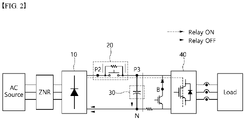
- FIG. 2 shows the flow of current during initial charging and inverter operation.
- the relay of the initial charging circuit 20 since the relay of the initial charging circuit 20 is in an off state, the output current of the rectifier 10 flows to the DC link capacitor 30 through the initial charging resistor of the initial charging circuit 20.
- the relay When the initial charging is finished, the relay is turned on and the output current of the rectifier 10 flows to the DC link capacitor 30 and the inductor 40 through the relay of the initial charging circuit 20.
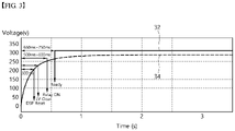
- FIG. 3 shows the voltage applied to the DC link capacitor according to time.
- the relay of the initial charging circuit When the DSP reset is canceled and the voltage of the DC link capacitor is higher than the low voltage clear (LV Clear) level, the relay of the initial charging circuit is on (Relay On), and after the ready point, a voltage 32 that does not pass through the initial charging resistor of the initial charging circuit is applied to the DC link capacitor as shown in the solid line. If the relay is not turned on and continues through the initial charging resistor, the voltage 34 applied to the DC link capacitor will appear as a dotted line due to the voltage drop due to the initial charging resistor.
- the inventors of the present invention have been researching and trying to solve the problems of the method for diagnosing a failure of an initial charging circuit of prior art.
- the present invention was completed after much effort to complete a device and method capable of effectively diagnosing the failure of an initial charging circuit while minimizing the addition of components for diagnosing the failure of an initial charging circuit.
- the device for diagnosing a failure of an inverter initial charging circuit includes a relay malfunction detector including a photocoupler having an input side connected in parallel to an initial charging resistor of the inverter initial charging circuit; a voltage detector including a first resistor connected in parallel with an output side of the photocoupler; and a controller for determining whether a relay malfunctions by an output voltage which is output from the first resistor of the voltage detector.
- the photocoupler of the relay malfunction detector is turned on when a current flows through the initial charging resistor.
- the voltage detector further includes a second resistor, the first resistor and the second resistor are connected in series, and the first resistor and the second resistor connected in series are preferably connected in parallel with a DC link capacitor of an inverter.
- the controller determines that the initial charging circuit is faulty when the output voltage of the first resistor becomes 0 after the initial charging of an inverter is completed and a run command is provided.
- the method for diagnosing a failure of an inverter initial charging circuit includes the steps of turning on a relay after the initial charging of an inverter is completed; starting operation of the inverter; detecting a voltage drop of a DC link capacitor; determining whether a photocoupler connected in parallel with an initial charging resistor of the inverter initial charging circuit is turned on/off; and determining that a relay of the initial charging circuit is malfunctioning when the photocoupler is in an on state.
- the step of determining whether the photocoupler is turned on/off is determining by measuring the voltage of a resistor connected in parallel with an output side of the photocoupler.
- FIG. 4 is a structural diagram of the device for diagnosing a failure of an initial charging circuit 100 according to a preferred exemplary embodiment of the present invention.
- the device for diagnosing a failure of an initial charging circuit 100 includes a relay malfunction detector 110, a voltage detector 120 and a controller 130.
- the relay malfunction detector 110 is connected in parallel with an initial charging resistor of an initial charging circuit to detect a relay malfunction.
- the voltage detector 120 is connected in parallel with a DC link capacitor to detect the voltage of a DC link capacitor and a voltage for determining a relay malfunction.
- the controller 130 includes one or more processors, and determines a malfunction of the relay based on the voltage detected by the relay voltage detector 120.
- FIG. 5 is a more detailed structural diagram of the device for diagnosing a failure of an initial charging circuit 100 according to the present invention.
- the relay malfunction detector 110 includes an input resistor 112 and a photocoupler 114.
- the input resistor 112 is connected in series to an input side of the photocoupler 114.
- the voltage detector 120 includes a first resistor 124, a second resistor 122 and a voltage measuring device 126.
- the first resistor 124 and the second resistor 122 are connected in series, and the first resistor 124 and the second resistor 122 connected in series are connected to the DC link capacitor in parallel.
- the first resistor 124 is connected in parallel to an output of the photocoupler 114 of the relay malfunction detector 110.
- the relay In the initial charging circuit, when the inverter is in the run state after the initial charging is completed, the relay is turned on, and thus, no current flows through the initial charging resistor. Then, a current does not flow even in the photocoupler 114 of the relay malfunction detector 110 such that the photocoupler 114 is in an open state.
- the voltage measuring device 126 measures the voltage applied to the first resistor 124, and since the first resistor 124 and the second resistor 122 are connected in series, the voltage across the DC link capacitor is divided according to the ratio of the resistance.
- the voltage applied to the DC link capacitor is 330V
- the first resistor 124 is 20 kiloohm
- the second resistor 122 is 200 kiloohm
- a voltage of 30V is applied to the first resistor 124 and a voltage of 300V is applied to the second resistor 122. Therefore, a voltage of 30V will be measured in the voltage measuring device 126.
- the relay of the initial charging circuit is not in an on state even though the inverter is in an operating state after the initial charging is completed, it may be determined that the relay is malfunctioning.
- the relay is in an off state, a current flows through the initial charging resistor, not the relay.
- a current also flows through a photodiode 114 connected in parallel, and the photodiode 114 is turned on.
- both ends of the photodiode 114 are short-circuited, and thus, both ends of the first resistor 124 of the voltage detector 120 are also short-circuited. Therefore, a voltage of 0 will be measured in the voltage measuring device 126 for measuring the voltage across the first resistor 124. In this case, the voltage across the DC link capacitor will appear to be lower than in the normal case due to the voltage dropped by the initial charging resistor.
- the controller 130 may determine that the relay of the initial charging circuit is faulty. Even if the voltage across the DC link capacitor appears to be lower than normal, if the value measured by the voltage measuring device 126 is higher than the reference value, it may be determined that this is not a relay failure but a light load operation of the inverter.
- FIG. 6 shows the reference voltage of a DC link capacitor for determining the failure of an initial charging circuit in a controller as described above.
- the SMPS for the operation of the entire inverter is always operated at a very small voltage 66 or higher.
- the operating voltage of the inverter is maintained between the overvoltage level 61 and the low voltage level 65 at which the relay is turned on after the initial charging is completed.
- the rated voltage should be maintained between the rated maximum voltage 62 and the rated minimum voltage 64.
- the DC link capacitor maintains a constant charging voltage 63, but in special circumstances such as a relay failure or light load operation, it may fall below the charging voltage 63.
- the controller may determine whether the voltage drop is a normal voltage drop or a voltage drop caused by a relay malfunction.
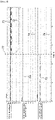
- FIG. 7 shows examples of signals detected when a relay malfunctions.
- a change in the signal appears at a time point 77 when the relay malfunction starts.
- the DC link voltage represents a voltage 71 measured before the initial charging circuit and a voltage 72 measured from the DC link capacitor. If the relay malfunctions, the ripple occurs in the voltage measured before the initial charging circuit because the output current of the rectifier passes through the initial charging resistor. In addition, the voltage 72 applied to the DC link capacitor is dropped due to the initial charging resistor.
- the relay malfunctions and is switched from an on state 73 to an off state 74.
- FIG. 8 is a flowchart of the method for diagnosing a failure of an inverter initial charging circuit according to another preferred exemplary embodiment of the present invention.
- the controller determines whether a voltage drop of the DC link capacitor has occurred (S60), and determines whether the voltage drop is due to a failure of the relay or a normal low voltage operation.
- the controller determines the state of the photocoupler connected in parallel to the initial charging resistor, and the state of the photocoupler is determined by the voltage applied to the resistor connected in parallel with the output side of the photocoupler.
- the voltage of the resistors connected in parallel becomes 0 when the photocoupler is in an on state, and when the photocoupler is in an off state, the voltage of the resistors connected in parallel becomes 0.
Landscapes
- Physics & Mathematics (AREA)
- General Physics & Mathematics (AREA)
- Engineering & Computer Science (AREA)
- Power Engineering (AREA)
- Inverter Devices (AREA)
- Testing Electric Properties And Detecting Electric Faults (AREA)
Abstract
Description
- This application claims priority to and the benefit of
Korean Patent Application No. 10-2020-0022386, filed on February 24, 2020 - The present invention relates to an inverter, and more particularly to an initial charging circuit of an inverter.
- The inverter is one of the representative power conversion devices along with the converter. The inverter receives AC power, converts it to DC and then converts it back to AC for controlling an electric motor to control the electric motor. It is used in various forms throughout the industry where electric motors are used, such as fans, pumps, elevators, transfer devices, production lines and the like. The converter is a device that converts AC or DC input power into DC, and the power conversion method is similar to that of an inverter, and similar to an inverter, it is used variously throughout the industry.
- An initial charging circuit is essential for an inverter. The initial charging circuit prevents an overcurrent from flowing in the DC link capacitor of the inverter due to the inrush current, and protects the devices from the parasitic inductance components of a rectifier and a DC terminal and the high voltage generated by the inrush current.
-
FIG. 1 shows the structure of a general inverter according to prior art. - The
rectifier 10 converts three-phase AC power into DC power to charge theDC link capacitor 30, and the DC power stored in theDC link capacitor 30 is again converted into AC power by theinverter 40 and transmitted to the electric motor. - In order to prevent an overcurrent from flowing in the
DC link capacitor 30 due to the inrush current, aninitial charging circuit 20 is required, and theinitial charging circuit 20 includes an initial charging resistor and a relay. -
FIG. 2 shows the flow of current during initial charging and inverter operation. - At the time of initial charging, since the relay of the
initial charging circuit 20 is in an off state, the output current of therectifier 10 flows to theDC link capacitor 30 through the initial charging resistor of theinitial charging circuit 20. When the initial charging is finished, the relay is turned on and the output current of therectifier 10 flows to theDC link capacitor 30 and theinductor 40 through the relay of theinitial charging circuit 20. -
FIG. 3 shows the voltage applied to the DC link capacitor according to time. - When the DSP reset is canceled and the voltage of the DC link capacitor is higher than the low voltage clear (LV Clear) level, the relay of the initial charging circuit is on (Relay On), and after the ready point, a
voltage 32 that does not pass through the initial charging resistor of the initial charging circuit is applied to the DC link capacitor as shown in the solid line. If the relay is not turned on and continues through the initial charging resistor, thevoltage 34 applied to the DC link capacitor will appear as a dotted line due to the voltage drop due to the initial charging resistor. - However, when a light load is applied to the inverter even when the relay is in an on state, a voltage drop may occur, and on/off of the relay cannot be distinguished simply by the voltage drop. Therefore, there is a problem in that it is impossible to determine whether the relay included in the initial charging circuit is faulty by the voltage drop of the DC link capacitor.
- The inventors of the present invention have been researching and trying to solve the problems of the method for diagnosing a failure of an initial charging circuit of prior art. The present invention was completed after much effort to complete a device and method capable of effectively diagnosing the failure of an initial charging circuit while minimizing the addition of components for diagnosing the failure of an initial charging circuit.
- It is an object of the present invention to provide a device and method capable of effectively diagnosing a failure of a relay while minimizing additional components.
- It is another object of the present invention to prevent power loss due to an initial charging resistor or component failure or burnout by diagnosing a failure of a relay by adding simple components.
- Meanwhile, other objects not specified in the present invention will be additionally considered within the range that can be easily inferred from the following detailed description and effects thereof.
- The device for diagnosing a failure of an inverter initial charging circuit according to the present invention includes a relay malfunction detector including a photocoupler having an input side connected in parallel to an initial charging resistor of the inverter initial charging circuit; a voltage detector including a first resistor connected in parallel with an output side of the photocoupler; and a controller for determining whether a relay malfunctions by an output voltage which is output from the first resistor of the voltage detector.
- The photocoupler of the relay malfunction detector is turned on when a current flows through the initial charging resistor.
- The voltage detector further includes a second resistor, the first resistor and the second resistor are connected in series, and the first resistor and the second resistor connected in series are preferably connected in parallel with a DC link capacitor of an inverter.
- The controller determines that the initial charging circuit is faulty when the output voltage of the first resistor becomes 0 after the initial charging of an inverter is completed and a run command is provided.
- The method for diagnosing a failure of an inverter initial charging circuit according to another exemplary embodiment of the present invention includes the steps of turning on a relay after the initial charging of an inverter is completed; starting operation of the inverter; detecting a voltage drop of a DC link capacitor; determining whether a photocoupler connected in parallel with an initial charging resistor of the inverter initial charging circuit is turned on/off; and determining that a relay of the initial charging circuit is malfunctioning when the photocoupler is in an on state.
- The step of determining whether the photocoupler is turned on/off is determining by measuring the voltage of a resistor connected in parallel with an output side of the photocoupler.
- According to the present invention, there is an effect of effectively detecting the failure of an initial charging circuit by adding a photocoupler that does not use a separate power source or controller.
- In addition, since the voltage detection method using the conventional OPAMP is not used, there is an advantage in that the cost can be reduced.
- Meanwhile, even if it is an effect not explicitly mentioned herein, it is added that the effects described in the following specification expected by the technical features of the present invention and their potential effects are treated as described in the specification of the present invention.
-
-
FIG. 1 is a structural diagram of a general inverter of prior art. -
FIG. 2 shows the flow of current according to the relay on/off in the inverter of prior art. -
FIG. 3 shows the level at which the voltage is charged in the DC link capacitor of prior art. -
FIG. 4 is a structural diagram of the device for diagnosing a failure of an inverter initial charging circuit according to a preferred exemplary embodiment of the present invention. -
FIG. 5 is a more detailed structural diagram of the device for diagnosing a failure of an inverter initial charging circuit according to the present invention. -
FIG. 6 shows voltage levels for each operation of the DC link capacitor. -
FIG. 7 shows examples of signals detected according to the present invention. -
FIG. 8 is a flowchart of the method for diagnosing a failure of an inverter initial charging circuit according to another preferred exemplary embodiment of the present invention. - It is revealed that the accompanying drawings are exemplified as a reference for understanding the technical idea of the present invention, and the scope of the present invention is not limited thereby.

- Hereinafter, the configuration of the present invention guided by various exemplary embodiments of the present invention and the effects resulting from the configuration will be described with reference to the drawings. In the description of the present invention, if it is determined that matters that are obvious to those skilled in the art may unnecessary obscure the gist of the present invention with respect to related known functions, the detailed description thereof will be omitted.
- Terms such as 'first' and 'second' may be used to describe various components, but the components should not be limited by the above terms. The above term may be used only for the purpose of distinguishing one component from another. For example, without departing from the scope of the present invention, a 'first component' may be termed a 'second component', and similarly, a 'second component' may also be termed a 'first component'. In addition, the singular expression includes the plural expression unless the context clearly dictates otherwise. Unless otherwise defined, terms used in the exemplary embodiments of the present invention may be interpreted as meanings commonly known to those of ordinary skill in the art.
- Hereinafter, the configuration of the present invention guided by various exemplary embodiments of the present invention and the effects resulting from the configuration will be described with reference to the drawings.
-
FIG. 4 is a structural diagram of the device for diagnosing a failure of aninitial charging circuit 100 according to a preferred exemplary embodiment of the present invention. - The device for diagnosing a failure of an
initial charging circuit 100 includes arelay malfunction detector 110, avoltage detector 120 and acontroller 130. - The
relay malfunction detector 110 is connected in parallel with an initial charging resistor of an initial charging circuit to detect a relay malfunction. - The
voltage detector 120 is connected in parallel with a DC link capacitor to detect the voltage of a DC link capacitor and a voltage for determining a relay malfunction. - The
controller 130 includes one or more processors, and determines a malfunction of the relay based on the voltage detected by therelay voltage detector 120. -
FIG. 5 is a more detailed structural diagram of the device for diagnosing a failure of aninitial charging circuit 100 according to the present invention. - The
relay malfunction detector 110 includes aninput resistor 112 and aphotocoupler 114. Theinput resistor 112 is connected in series to an input side of thephotocoupler 114. - The
voltage detector 120 includes afirst resistor 124, asecond resistor 122 and avoltage measuring device 126. Thefirst resistor 124 and thesecond resistor 122 are connected in series, and thefirst resistor 124 and thesecond resistor 122 connected in series are connected to the DC link capacitor in parallel. Thefirst resistor 124 is connected in parallel to an output of thephotocoupler 114 of therelay malfunction detector 110. - In the initial charging circuit, when the inverter is in the run state after the initial charging is completed, the relay is turned on, and thus, no current flows through the initial charging resistor. Then, a current does not flow even in the
photocoupler 114 of therelay malfunction detector 110 such that thephotocoupler 114 is in an open state. When thephotocoupler 114 is in an open state, thevoltage measuring device 126 measures the voltage applied to thefirst resistor 124, and since thefirst resistor 124 and thesecond resistor 122 are connected in series, the voltage across the DC link capacitor is divided according to the ratio of the resistance. For example, if the voltage applied to the DC link capacitor is 330V, thefirst resistor 124 is 20 kiloohm, and thesecond resistor 122 is 200 kiloohm, since only 1/10 of the voltage applied to thesecond resistor 122 is applied to thefirst resistor 124, a voltage of 30V is applied to thefirst resistor 124 and a voltage of 300V is applied to thesecond resistor 122. Therefore, a voltage of 30V will be measured in thevoltage measuring device 126. - On the other hand, if the relay of the initial charging circuit is not in an on state even though the inverter is in an operating state after the initial charging is completed, it may be determined that the relay is malfunctioning. When the relay is in an off state, a current flows through the initial charging resistor, not the relay. When a current flows through the initial charging resistor, a current also flows through a
photodiode 114 connected in parallel, and thephotodiode 114 is turned on. - When the
photodiode 114 is turned on, both ends of thephotodiode 114 are short-circuited, and thus, both ends of thefirst resistor 124 of thevoltage detector 120 are also short-circuited. Therefore, a voltage of 0 will be measured in thevoltage measuring device 126 for measuring the voltage across thefirst resistor 124. In this case, the voltage across the DC link capacitor will appear to be lower than in the normal case due to the voltage dropped by the initial charging resistor. - If the voltage across the DC link capacitor appears to be lower than normal and the voltage measured by the
voltage measuring device 126 is lower than a reference value, thecontroller 130 may determine that the relay of the initial charging circuit is faulty. Even if the voltage across the DC link capacitor appears to be lower than normal, if the value measured by thevoltage measuring device 126 is higher than the reference value, it may be determined that this is not a relay failure but a light load operation of the inverter. -
FIG. 6 shows the reference voltage of a DC link capacitor for determining the failure of an initial charging circuit in a controller as described above. - The SMPS for the operation of the entire inverter is always operated at a very
small voltage 66 or higher. - The operating voltage of the inverter is maintained between the
overvoltage level 61 and thelow voltage level 65 at which the relay is turned on after the initial charging is completed. Preferably, the rated voltage should be maintained between the ratedmaximum voltage 62 and the ratedminimum voltage 64. In the relay on state, since there is no voltage drop due to the initial charging resistor, the DC link capacitor maintains aconstant charging voltage 63, but in special circumstances such as a relay failure or light load operation, it may fall below the chargingvoltage 63. In this case, by therelay malfunction detector 110 and thevoltage detector 120, the controller may determine whether the voltage drop is a normal voltage drop or a voltage drop caused by a relay malfunction. -
FIG. 7 shows examples of signals detected when a relay malfunctions. - A change in the signal appears at a
time point 77 when the relay malfunction starts. - The DC link voltage represents a
voltage 71 measured before the initial charging circuit and avoltage 72 measured from the DC link capacitor. If the relay malfunctions, the ripple occurs in the voltage measured before the initial charging circuit because the output current of the rectifier passes through the initial charging resistor. In addition, thevoltage 72 applied to the DC link capacitor is dropped due to the initial charging resistor. - The relay malfunctions and is switched from an on
state 73 to anoff state 74. - When the
photocoupler 114 is turned on when the relay malfunctions, thevoltage 76 detected by thevoltage detector 120 drops to zero. -
FIG. 8 is a flowchart of the method for diagnosing a failure of an inverter initial charging circuit according to another preferred exemplary embodiment of the present invention. - When the power of the inverter is turned on (S10) and the SMPS for overall control of the inverter operates (S20), initial charging starts.
- When the voltage charged in the DC link capacitor reaches an inverter low voltage clear (LV Clear) level (S30), when the initial charging is finished and the relay of the initial charging circuit is switched on (S40), the inverter starts to operate (Run) (S50).
- The controller determines whether a voltage drop of the DC link capacitor has occurred (S60), and determines whether the voltage drop is due to a failure of the relay or a normal low voltage operation.
- To this end, the controller determines the state of the photocoupler connected in parallel to the initial charging resistor, and the state of the photocoupler is determined by the voltage applied to the resistor connected in parallel with the output side of the photocoupler. When the photocoupler is in an on state, the voltage of the resistors connected in parallel becomes 0 when the photocoupler is in an on state, and when the photocoupler is in an off state, the voltage of the resistors connected in parallel becomes 0.
- Therefore, it is determined whether the voltage detected at the resistor connected in parallel with the photocoupler is below a reference voltage (S70), and if it is below the reference voltage, it is determined that the relay is malfunctioning (S80), and it may display a warning message or stop the operation of the inverter.
- According to the present invention as described above, there is an effect of effectively determining whether the relay of the initial charging circuit is faulty by the photocoupler, which does not require a separate power source or controller.
- The protection scope of the present invention is not limited to the description and expression of the exemplary embodiments explicitly described above. In addition, it is added once again that the protection scope of the present invention cannot be limited due to obvious changes or substitutions in the technical field to which the present invention pertains.
Claims (6)
- A device for diagnosing a failure of an inverter initial charging circuit, comprising:a relay malfunction detector comprising a photocoupler having an input side connected in parallel to an initial charging resistor of the inverter initial charging circuit;a voltage detector comprising a first resistor connected in parallel with an output side of the photocoupler; anda controller for determining whether a relay malfunctions by an output voltage which is output from the first resistor of the voltage detector.
- The device of claim 1, wherein the photocoupler of the relay malfunction detector is turned on when a current flows through the initial charging resistor.
- The device of claim 1, wherein the voltage detector further comprises a second resistor, the first resistor and the second resistor are connected in series, and the first resistor and the second resistor connected in series are connected in parallel with a DC link capacitor of an inverter.
- The device of claim 1, wherein the controller determines that the initial charging circuit is faulty when the output voltage of the first resistor becomes 0 after the initial charging of an inverter is completed and a run command is provided.
- A method for diagnosing a failure of an inverter initial charging circuit, which is performed by a controller comprising one or more processors, the method comprising the steps of:turning on a relay after the initial charging of an inverter is completed;starting operation of the inverter;detecting a voltage drop of a DC link capacitor;determining whether a photocoupler connected in parallel with an initial charging resistor of the inverter initial charging circuit is turned on/off; anddetermining that a relay of the initial charging circuit is malfunctioning when the photocoupler is in an on state.
- The method of claim 5, wherein the step of determining whether the photocoupler is turned on/off is determining by measuring the voltage of a resistor connected in parallel with an output side of the photocoupler.
Applications Claiming Priority (2)
| Application Number | Priority Date | Filing Date | Title |
|---|---|---|---|
| KR1020200022386A KR102520182B1 (en) | 2020-02-24 | 2020-02-24 | Apparatus and method for diagnosing initial charging circuit of inverter |
| PCT/KR2021/000189 WO2021172736A1 (en) | 2020-02-24 | 2021-01-07 | Device and method for diagnosing failure of inverter initial charging circuit |
Publications (2)
| Publication Number | Publication Date |
|---|---|
| EP4113143A1 true EP4113143A1 (en) | 2023-01-04 |
| EP4113143A4 EP4113143A4 (en) | 2024-03-27 |
Family
ID=77491133
Family Applications (1)
| Application Number | Title | Priority Date | Filing Date |
|---|---|---|---|
| EP21761792.7A Pending EP4113143A4 (en) | 2020-02-24 | 2021-01-07 | Device and method for diagnosing failure of inverter initial charging circuit |
Country Status (5)
| Country | Link |
|---|---|
| US (1) | US12270832B2 (en) |
| EP (1) | EP4113143A4 (en) |
| KR (1) | KR102520182B1 (en) |
| CN (1) | CN115136013B (en) |
| WO (1) | WO2021172736A1 (en) |
Families Citing this family (2)
| Publication number | Priority date | Publication date | Assignee | Title |
|---|---|---|---|---|
| CN115166508B (en) * | 2022-09-08 | 2022-11-22 | 深圳市云天数字能源有限公司 | Failure detection method and relay failure detection device for grid-connected inverter |
| KR102731790B1 (en) * | 2022-11-02 | 2024-11-18 | 엘에스일렉트릭(주) | Input voltage calculation system and method using DC link voltage in inverter |
Family Cites Families (15)
| Publication number | Priority date | Publication date | Assignee | Title |
|---|---|---|---|---|
| JPH0723523A (en) | 1993-06-30 | 1995-01-24 | Juki Corp | Inrush prevention circuit failure detection device |
| US6084785A (en) * | 1997-03-19 | 2000-07-04 | Hitachi, Ltd. | Electric power converter |
| KR100381191B1 (en) * | 2000-10-02 | 2003-04-26 | 엘지전자 주식회사 | A decision apparatus for washing pattern |
| JP2003174778A (en) * | 2001-12-06 | 2003-06-20 | Matsushita Electric Ind Co Ltd | Relay non-operation detecting circuit and motor control device including the same |
| KR20060090127A (en) * | 2005-02-07 | 2006-08-10 | 오티스엘리베이터 유한회사 | Motor Drive System and Motor Drive Method |
| KR101365753B1 (en) * | 2007-04-23 | 2014-02-21 | 페어차일드코리아반도체 주식회사 | Converter and the driving method thereof |
| US7791847B2 (en) * | 2007-12-28 | 2010-09-07 | Delta Electronics, Inc. | Fault-sensing and protecting apparatus for soft start circuit of inverter and method for the same |
| JP5728914B2 (en) | 2010-12-02 | 2015-06-03 | 富士電機株式会社 | Inverter device |
| US9726725B2 (en) * | 2013-08-02 | 2017-08-08 | Jtekt Corporation | Power circuit abnormality detection method |
| KR20160093206A (en) * | 2015-01-28 | 2016-08-08 | 엘에스산전 주식회사 | Inverter control device with scr failure detection circuit |
| KR102526874B1 (en) * | 2016-04-26 | 2023-04-27 | 엘에스일렉트릭(주) | Apparatus for controlling operation of power conversion device |
| KR101689993B1 (en) * | 2016-04-27 | 2016-12-26 | 엘에스산전 주식회사 | Apparatus for detecting malfuction of relay |
| US9899953B2 (en) * | 2016-06-27 | 2018-02-20 | Rockwell Automation Technologies, Inc. | Method and apparatus for detecting ground faults in inverter outputs on a shared DC bus |
| KR102307999B1 (en) * | 2017-03-06 | 2021-09-30 | 엘에스일렉트릭(주) | Device detecting fault of inverter power relay |
| CN109342935A (en) * | 2018-10-08 | 2019-02-15 | 珠海格力电器股份有限公司 | Device and method for detecting failure of direct-current bus charging circuit relay and motor |
-
2020
- 2020-02-24 KR KR1020200022386A patent/KR102520182B1/en active Active
-
2021
- 2021-01-07 WO PCT/KR2021/000189 patent/WO2021172736A1/en not_active Ceased
- 2021-01-07 CN CN202180015040.1A patent/CN115136013B/en active Active
- 2021-01-07 EP EP21761792.7A patent/EP4113143A4/en active Pending
- 2021-01-07 US US17/801,413 patent/US12270832B2/en active Active
Also Published As
| Publication number | Publication date |
|---|---|
| KR102520182B1 (en) | 2023-04-07 |
| WO2021172736A1 (en) | 2021-09-02 |
| CN115136013B (en) | 2026-02-06 |
| EP4113143A4 (en) | 2024-03-27 |
| KR20210107414A (en) | 2021-09-01 |
| US12270832B2 (en) | 2025-04-08 |
| CN115136013A (en) | 2022-09-30 |
| US20230078868A1 (en) | 2023-03-16 |
Similar Documents
| Publication | Publication Date | Title |
|---|---|---|
| US8711587B2 (en) | Power converter with a variable reference voltage and inrush current limiting | |
| US9954432B2 (en) | Power supply apparatus with soft-start and protection | |
| US20150036397A1 (en) | Inverter and over current protection method thereof | |
| US20150155794A1 (en) | Short Circuit Protection | |
| CA2999318C (en) | Power supply apparatus with soft-start and protection | |
| US9692314B2 (en) | Detection circuit and three-phase AC-to-AC power converting apparatus incorporating the same | |
| EP2164160B1 (en) | Voltage reduction detection circuit and switching power supply system | |
| US20180278052A1 (en) | Converter apparatus having function of detecting short circuit failure, and method for detecting short circuit failure of converter apparatus | |
| EP4113143A1 (en) | Device and method for diagnosing failure of inverter initial charging circuit | |
| JP5106484B2 (en) | Variable power supply device, motor drive control device, and protection circuit operating method thereof | |
| JP2011067037A (en) | Overvoltage protection circuit | |
| JP2011160517A (en) | Overcurrent protection circuit, and switching power supply device | |
| CN113507772A (en) | Hysteresis circuit, emergency lighting circuit and lighting equipment | |
| CN110562811B (en) | Safety loop state detection device and elevator system | |
| KR20210107415A (en) | Apparatus and method for diagnosing initial charging circuit of inverter | |
| JP2012210029A (en) | Dc power supply | |
| CN111917102B (en) | Overvoltage protection circuit and power supply device | |
| US10072666B2 (en) | Hermetic compressor driving device | |
| CN215991299U (en) | Hysteresis circuit, emergency lighting circuit and lighting equipment | |
| US12085594B2 (en) | Method and circuit arrangement for ascertaining a type and value of an input voltage | |
| CN214795020U (en) | Phase-loss detection circuit and electronic equipment | |
| JP4851183B2 (en) | Capacitor input type rectifier circuit having overcurrent detection function and inverter device using the same | |
| JP2006340532A (en) | Inrush current prevention circuit and power conversion device | |
| JP5959010B2 (en) | Overcurrent detection device | |
| JPH07184316A (en) | Open phase detecting circuit |
Legal Events
| Date | Code | Title | Description |
|---|---|---|---|
| STAA | Information on the status of an ep patent application or granted ep patent |
Free format text: STATUS: THE INTERNATIONAL PUBLICATION HAS BEEN MADE |
|
| PUAI | Public reference made under article 153(3) epc to a published international application that has entered the european phase |
Free format text: ORIGINAL CODE: 0009012 |
|
| STAA | Information on the status of an ep patent application or granted ep patent |
Free format text: STATUS: REQUEST FOR EXAMINATION WAS MADE |
|
| 17P | Request for examination filed |
Effective date: 20220906 |
|
| AK | Designated contracting states |
Kind code of ref document: A1 Designated state(s): AL AT BE BG CH CY CZ DE DK EE ES FI FR GB GR HR HU IE IS IT LI LT LU LV MC MK MT NL NO PL PT RO RS SE SI SK SM TR |
|
| DAV | Request for validation of the european patent (deleted) | ||
| DAX | Request for extension of the european patent (deleted) | ||
| REG | Reference to a national code |
Ref country code: DE Ref legal event code: R079 Free format text: PREVIOUS MAIN CLASS: G01R0031400000 Ipc: G01R0031327000 |
|
| A4 | Supplementary search report drawn up and despatched |
Effective date: 20240222 |
|
| RIC1 | Information provided on ipc code assigned before grant |
Ipc: G01R 31/42 20060101ALI20240216BHEP Ipc: G01R 31/327 20060101AFI20240216BHEP |
|
| GRAP | Despatch of communication of intention to grant a patent |
Free format text: ORIGINAL CODE: EPIDOSNIGR1 |
|
| STAA | Information on the status of an ep patent application or granted ep patent |
Free format text: STATUS: GRANT OF PATENT IS INTENDED |
|
| INTG | Intention to grant announced |
Effective date: 20260202 |
|
| GRAS | Grant fee paid |
Free format text: ORIGINAL CODE: EPIDOSNIGR3 |
|
| P01 | Opt-out of the competence of the unified patent court (upc) registered |
Free format text: CASE NUMBER: UPC_APP_0010827_4113143/2026 Effective date: 20260324 |
|
| GRAA | (expected) grant |
Free format text: ORIGINAL CODE: 0009210 |
|
| STAA | Information on the status of an ep patent application or granted ep patent |
Free format text: STATUS: THE PATENT HAS BEEN GRANTED |