EP4113131B1 - Schätzung der auf einer phase verbrauchten leistung trotz eines betrugs - Google Patents
Schätzung der auf einer phase verbrauchten leistung trotz eines betrugs Download PDFInfo
- Publication number
- EP4113131B1 EP4113131B1 EP22180271.3A EP22180271A EP4113131B1 EP 4113131 B1 EP4113131 B1 EP 4113131B1 EP 22180271 A EP22180271 A EP 22180271A EP 4113131 B1 EP4113131 B1 EP 4113131B1
- Authority
- EP
- European Patent Office
- Prior art keywords
- voltage
- phase
- samples
- estimated
- estimation method
- Prior art date
- Legal status (The legal status is an assumption and is not a legal conclusion. Google has not performed a legal analysis and makes no representation as to the accuracy of the status listed.)
- Active
Links
- 239000000523 sample Substances 0.000 claims description 62
- 238000000034 method Methods 0.000 claims description 50
- 238000005259 measurement Methods 0.000 claims description 41
- 230000010363 phase shift Effects 0.000 claims description 28
- 230000007935 neutral effect Effects 0.000 claims description 12
- 238000004364 calculation method Methods 0.000 claims description 11
- 238000001914 filtration Methods 0.000 claims description 7
- 239000013074 reference sample Substances 0.000 claims description 5
- 238000004590 computer program Methods 0.000 claims description 4
- 230000005611 electricity Effects 0.000 claims 3
- 101100446506 Mus musculus Fgf3 gene Proteins 0.000 description 10
- 238000009434 installation Methods 0.000 description 8
- 230000006870 function Effects 0.000 description 6
- 238000010586 diagram Methods 0.000 description 4
- 238000005070 sampling Methods 0.000 description 3
- 239000004020 conductor Substances 0.000 description 2
- 240000008042 Zea mays Species 0.000 description 1
- 238000003491 array Methods 0.000 description 1
- 238000001514 detection method Methods 0.000 description 1
- 230000009466 transformation Effects 0.000 description 1
Images

Classifications
-
- G—PHYSICS
- G01—MEASURING; TESTING
- G01R—MEASURING ELECTRIC VARIABLES; MEASURING MAGNETIC VARIABLES
- G01R22/00—Arrangements for measuring time integral of electric power or current, e.g. electricity meters
- G01R22/06—Arrangements for measuring time integral of electric power or current, e.g. electricity meters by electronic methods
- G01R22/061—Details of electronic electricity meters
- G01R22/066—Arrangements for avoiding or indicating fraudulent use
-
- G—PHYSICS
- G01—MEASURING; TESTING
- G01R—MEASURING ELECTRIC VARIABLES; MEASURING MAGNETIC VARIABLES
- G01R21/00—Arrangements for measuring electric power or power factor
- G01R21/133—Arrangements for measuring electric power or power factor by using digital technique
- G01R21/1331—Measuring real or reactive component, measuring apparent energy
-
- G—PHYSICS
- G01—MEASURING; TESTING
- G01R—MEASURING ELECTRIC VARIABLES; MEASURING MAGNETIC VARIABLES
- G01R22/00—Arrangements for measuring time integral of electric power or current, e.g. electricity meters
- G01R22/06—Arrangements for measuring time integral of electric power or current, e.g. electricity meters by electronic methods
- G01R22/10—Arrangements for measuring time integral of electric power or current, e.g. electricity meters by electronic methods using digital techniques
-
- G—PHYSICS
- G01—MEASURING; TESTING
- G01R—MEASURING ELECTRIC VARIABLES; MEASURING MAGNETIC VARIABLES
- G01R11/00—Electromechanical arrangements for measuring time integral of electric power or current, e.g. of consumption
- G01R11/02—Constructional details
- G01R11/24—Arrangements for avoiding or indicating fraudulent use
Definitions
- the invention relates to the field of three-phase electric meters.
- Electric meters used in industrial applications, frequently measure electrical powers and energies which are distributed via very high current levels (up to 2000A typically). These meters are generally three-phase meters.
- Such a meter has current inputs and voltage inputs.
- Each current sensor is connected to a current input by two conductive wires.
- the counter thus acquires, for each phase, an image of the current flowing on said phase.
- Each voltage input is conventionally connected to a phase by a conductive wire.
- the meter thus directly accesses the voltage present on each phase via the associated conductive wire.
- a known fraud consists of cutting one or more conductive wires which connect the phases to the voltage inputs.
- the aim of such fraud is to undervalue the total energy consumed which is measured by the meter, so as to reduce the bill to be paid to the electrical energy distributor.
- the meters of the prior art continue to carry out metrological measurements as they are. on the three phases, without taking into account fraud, and therefore effectively undervalue the energy consumed. Even if the fraud is detected, the distributor does not know the energy actually consumed by the fraudster's installation. However, it can prove useful to know the energy actually consumed, for example to demand payment from the fraudster for unbilled energy (in addition to possible penalties aimed at punishing the attempted fraud).
- EP 0 455 518 A2 discloses a method for estimating the power consumed on a phase, despite fraud, where the energy consumed is estimated from an estimate of the voltage on the distorted phase and the current measured on this phase.
- US 2012/306290 A1 discloses a method for controlling a cutting device where only one voltage is measured and the other two are reconstituted by calculation, filtering, phase shift of k*120° taking into account the acquired voltage.
- US 6,236,197 B1 discloses a method for determining fraud on a three-phase system.
- the object of the invention is to estimate, despite fraud consisting in falsely measuring voltage on a phase, the total energy consumed by an installation.
- the measurements of the first phase voltage are distorted and are therefore not usable.
- the power estimation method according to the invention therefore replaces the measurements of the first phase voltage with first estimated samples which are reconstituted from measurements of the second phase voltage which are not distorted by fraud .
- the method then estimates the first electrical powers consumed on the first phase using the first estimated voltage samples.
- the energy distributor can therefore obtain, despite the fraud, a relatively precise estimate of the total electrical power and the total energy actually consumed by the installation.
- a power estimation method as previously described, comprising the step, if ⁇ 1 is not an integer, of calculating the estimated value by carrying out a linear interpolation between the second voltage sample V 2 n- INT( ⁇ 1)-1 and the second voltage sample V 2 n-INT( ⁇ 1) , INT being the integer part function.
- the at least one first electrical power comprises a first Active Power estimated from the first estimated voltage samples and first current samples, images over time of a first phase current circulating on the first phase, and/or a first Reactive Power estimated from samples of a level on a fundamental frequency of the first phase voltage and samples of a level on a fundamental frequency of the first phase current, and/or a first Apparent Power estimated from an effective value of the first voltage of phase and an effective value of the first phase current.
- a power estimation method as previously described, further comprising the steps of detecting whether or not the distribution network includes a neutral in addition to the three phases and, if this is not the case, of calculate second corrected voltage samples, and calculate at least a second corrected electrical power consumed on the second phase from the second corrected voltage samples.
- X being a positive predefined value and less than 30.
- a computer-readable recording medium is provided, on which the computer program as previously described is recorded.
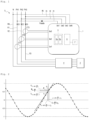
- the power estimation method according to a first embodiment of the invention is implemented in a three-phase electric meter 1 which is intended to measure the electrical energy supplied to the installation 2 of a subscriber by a network distribution 3.
- This installation 2 is an industrial installation.
- the distribution network 3 therefore comprises a first phase Ph1, a second phase Ph2, a third phase Ph3 and a neutral N.
- a circuit breaker 4 is positioned "on the border" between the distribution network 3 and the installation 2. The three phases Ph1, Ph2, Ph3 and neutral N enter circuit breaker 4 and exit towards installation 2. Circuit breaker 4 cuts off the distribution of electrical energy.
- Meter 1 includes four voltage inputs Ue1, Ue2, Ue3, UeN and three current inputs Ie1, Ie2, Ie3 (each current input including two ports).
- the voltage input Ue1 is connected to the first phase Ph1 by a conducting wire f1
- the voltage input Ue2 is connected to the second phase Ph2 by a conducting wire f2
- the voltage input Ue3 is connected to the third phase Ph3 by a conductor wire f3
- the voltage input UeN is connected to neutral N by a conductor wire fN.
- the current input Ie1 is connected to an external current transformer CT1 mounted on the first phase Ph1
- the current input Ie2 is connected to an external current transformer CT2 mounted on the second phase Ph2
- the current input Ie3 is connected to an external current transformer CT3 mounted on the third phase Ph3.
- External current transformers are located outside of meter 1.
- Each external current transformer here has a transformation ratio equal to 2000.
- the counter 1 recovers, at the level of the current inputs Ie1, Ie2, Ie3, and thanks to the external transformers CT1, CT2 and CT3, an image of the phase currents I1, 12, 13 circulating on the phases Ph1 , Ph2 and Ph3.
- Counter 1 also recovers, on the voltage inputs Ue1, Ue2, Ue3 and UeN, the phase voltages V1, V2, V3 present on the phases Ph1, Ph2, Ph3 and the neutral voltage VN present on the neutral N.
- the counter 1 further comprises measuring components 5 including front-end components 5a and converters digital analog converters 5b (or a single digital analog converter having a sufficient number of inputs).
- the front-end components 5a are connected to the current inputs and voltage inputs.
- the front-end components 5a make it possible to transform the currents on the current inputs into voltages suitable for the analog-to-digital converters 5b.
- the front-end components 5a also make it possible to transform the voltages on the voltage inputs into voltages suitable for the analog-to-digital converters 5b.
- the counter 1 also includes a processing component 6.
- the processing component 6 is adapted to execute instructions of a program to implement the power estimation method according to the invention.
- the program is stored in a memory 7, which is integrated into or connected to the processing component 6.
- the processing component 6 is for example a conventional processor, a microcontroller, a DSP (for Digital Signal Processor , which can be translated by “digital signal processor”), or a programmable logic circuit such as an FPGA (for Field Programmable Gate Arrays ) or an ASIC (for Application Specifies Integrated Circuit ) .
- the processing component 6 is a microcontroller 6.
- the microcontroller 6 is connected to the analog-digital converters 5b and acquires the measurement samples produced by the analog-digital converters 5b.
- the microcontroller 6 thus acquires first voltage samples V 1 not and first current samples I 1 not , images in time respectively of the first phase voltage V1 and the first phase current I1.
- the microcontroller 6 also acquires second voltage samples V 2 not and second current samples I 2 not , images in time respectively of the second phase voltage V2 and the second phase current I2.
- the microcontroller also acquires third voltage samples V 3 not and third samples of current I 3 not , images in time respectively of the third phase voltage V3 and the third phase current I3.
- the microcontroller 6 attempts to detect the fraudulent interruption of one or more conductive wires f1, f2, f3, which distorts the measurements of one or more phase voltages.
- the microcontroller 6 detects a cut in the conductive wire of a phase in the absence of voltage and in the presence of current on said phase.
- the microcontroller 6 detects fraud when the first phase voltage is lower than a predefined voltage threshold while the first phase current is greater than a predefined current threshold.
- the microcontroller 6 here calculates V1 RMS , which is the effective value of the first phase voltage V1, and I1 RMS , which is the effective value of the first phase current I1, and detects fraud on the first phase Ph1 when: V 1 RMS ⁇ Vf And I 1 RMS > Yew ,
- Vf being the predefined voltage threshold and If being the predefined current threshold.
- Istart being the current value from which counter 1 begins to measure the energy consumed
- Imin being the current value from which counter 1 must measure the current with the nominal precision
- Vf 40V.
- This fraud detection step is carried out in the same way for the other two phases.
- the measurements of the first phase voltage V1 are therefore distorted by fraud, and the first voltage samples cannot be used.
- the microcontroller 6 will therefore estimate at least a first electrical power consumed on the first phase Ph1 using the voltage measurements on a reference phase which is not subject to fraud.
- This reference phase is here for example the second phase Ph2 (but could also have been the third phase Ph3).
- the microcontroller 6 reconstitutes first estimated voltage samples U 1 n , images over time of the first phase voltage V1, from second samples of voltage V 2 n , images over time of the second phase voltage V2.
- the reconstruction is carried out by successive measurement periods, each having for example a duration of 1s.
- Each phase voltage has a network frequency equal to 50Hz, and therefore a network period equal to 20ms.
- N the number of samples per network period (N is therefore the number of first voltage samples per period of the first phase voltage), and ⁇ the number of network periods per measurement period.
- ⁇ 50.
- ⁇ N samples per measurement period 1s.
- N is a multiple of 4.
- N 52.
- the microcontroller 6 first acquires a first offset of index ⁇ 1 corresponding to a theoretical phase shift expected without fraud between the first phase voltage V1 and the second phase voltage V2.
- the first index shift has been pre-recorded in memory 7.
- the expected theoretical phase shift is equal to +120°.
- the first index shift ⁇ 1 is a number of samples for which the second voltage samples V 2 n must be shifted to produce a voltage in phase with the first phase voltage V1, taking into account the expected theoretical phase shift, and considering that an index shift equal to the total number of samples per network period (i.e. N) would correspond to a phase shift of 360°.
- the microcontroller 6 For each first estimated voltage sample U 1 n , if the first index offset ⁇ 1 is an integer, the microcontroller 6 gives said first estimated voltage sample a value of a second voltage sample having as second index the first index n offset from the first offset of index ⁇ 1. Otherwise, the microcontroller 6 gives the first estimated voltage sample U 1 n a value estimated from an interpolation using at least a second voltage sample.
- V 2 n-2N / 3 does not exist, and the microcontroller 6 uses at least one second existing voltage sample to produce an estimated value of the first estimated voltage sample U 1 n .
- the microcontroller 6 calculates the estimated value by carrying out a linear interpolation between the second voltage sample V 2 n - INT ( ⁇ 1)-1 and the second voltage sample V 2 n-INT ( ⁇ 1) ' that is to say -say between V 2 not ⁇ INT 2 NOT 3 ⁇ 1 And V 2 not ⁇ INT 2 NOT 3 .
- INT is the “integer part” function.
- the microcontroller 6 therefore determines the value of the sample U 1 n at the precise moment n - 2 N /3.
- the principle of linear interpolation consists of making an estimate of V 2 not ⁇ 2 NOT 3 corresponding to the point of the sinusoid at instant ( not ⁇ 2 NOT 3 ).
- T E by approximating to 1st order the sinusoid by the tangent passing through the 2 points A 1 not ⁇ INT 2 NOT 3 ⁇ 1 .
- T E ; V 2 not ⁇ INT 2 NOT 3 .
- V 2 not ⁇ 2 NOT 3 V 2 not ⁇ INT 2 NOT 3 ⁇ V 2 not ⁇ INT 2 NOT 3 ⁇ V 2 not ⁇ INT 2 NOT 3 ⁇ 1 ⁇ 2 NOT 3 ⁇ INT 2 NOT 3
- 2N/3 is not an integer and the estimation by linear interpolation is carried out systematically to reconstruct each first estimated voltage sample.
- the microcontroller 6 calculates a value of at least a first electrical power consumed on the first phase V1.
- the at least one first electrical power calculated by the microcontroller 6 here comprises a first Active Power estimated from the first estimated voltage samples U 1 n and the first current samples I 1 n , a first Reactive Power estimated from samples of a level on the fundamental frequency of the first phase voltage V1 and samples of a level on the fundamental frequency of the first phase current I1, and a first Apparent Power estimated from an effective value of the first phase voltage V1 and an effective value of the first phase current I1. Measurements of energy consumed as a function of time arise from these power estimates.
- U F1 not is the nth sample of the level on the fundamental frequency of the first phase voltage V1.
- I F1 not is the nth sample of the level on the fundamental frequency of the first phase current I1.
- V1 RMS and I1 RMS values are obtained by calculation from the samples U 1 n and I 1 n .
- the samples U F 1 n of the level on the fundamental frequency of the first phase voltage V1 and the samples I F 1 n of the level on the fundamental frequency of the first phase current I1 are obtained by low-pass filtering respectively of the first samples estimated voltage U 1 not (reconstituted) and the first samples of current I 1 not .
- Low-pass filtering here uses a first-order Butterworth filter.
- U F 3 not U 3 not + U 3 not ⁇ 1 + has .
- I F 1 not I 2 not + I 2 not ⁇ 1 + has .
- I F 3 not I 3 not + I 3 not ⁇ 1 + has .
- the microcontroller 6 uses the second voltage samples V 2 n again to reconstitute the third estimated voltage samples U 3 n and estimates at least a third electrical power consumed on the third phase Ph3 using the third estimated voltage samples U 3 n .
- the microcontroller 6 first acquires a third offset of index ⁇ 3 corresponding to a theoretical phase shift expected without fraud between the third phase voltage V3 and the second phase voltage V2.
- the expected theoretical phase shift is equal to -120°.
- the third index shift ⁇ 3 is a number of samples for which it is necessary to shift the second voltage samples V 2 n to produce a voltage in phase with the third phase voltage V3 taking into account the expected theoretical phase shift, considering that an index shift equal to the total number of samples per network period (i.e. N) would correspond to a phase shift of 360°.
- V 2 nN/3 does not exist, and the microcontroller 6 uses at least a second existing voltage sample to produce an estimated value of the third estimated voltage sample U 3 not .
- the microcontroller 6 calculates the estimated value by carrying out a linear interpolation between the second voltage sample V 2 n-INT( ⁇ 3)-1 and the second voltage sample V 2 n-INT( ⁇ 3) , that is to say between V 2 not ⁇ INT NOT 3 ⁇ 1 And V 2 not ⁇ INT NOT 3 .
- the microcontroller 6 therefore determines the value of the sample U 3 not at the precise moment n - N/3.
- N/3 is not an integer and the estimation by linear interpolation is carried out systematically.
- the samples U F 3 n and I F 3 n are calculated by application of the Butterworth filter as previously described.
- the V 3 RMS and I 3 RMS values are obtained by calculation from the U 3 samples not and I 3 not .
- Distribution network 3 includes a first phase Ph1, a second phase Ph2 and a third phase Ph3, but no neutral.
- Counter 1 includes three voltage inputs Ue1, Ue2, Ue3 and three current inputs Ie1, Ie2, Ie3 (each current input including two ports).
- the counter 1 again comprises measuring components 5 comprising front-end components 5a and analog-to-digital converters 5b, and a microcontroller 6 connected to the analog-to-digital converters 5b.
- V 1 RMS 40 V And I 1 RMS > 5 my .
- the microcontroller 6 has therefore detected a fraud which distorts the measurements of the first phase voltage V1.
- the implementation of the invention is slightly different in the three-wire configuration.
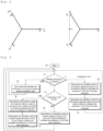
- figure 4 represents, in the four-wire configuration of the figure 1 , the Fresnel diagram of voltages and currents in the normal case (left), and in the event of fraud consisting of cutting the conductive wire f1 (right).
- FIG. 5 represents, in the three-wire configuration of the Figure 3 , the Fresnel diagram of voltages and currents in the normal case (left) and in the event of fraud consisting of cutting the conductive wire f1 (right).
- the microcontroller 6 therefore first of all detects, in a preliminary manner, whether or not the distribution network 3 includes a neutral in addition to the three phases.
- the microcontroller 6 takes into account the factor 3 2 and phase shifts of +30° and -30° to estimate electrical powers.
- the microcontroller 6 will first calculate second corrected voltage samples U 2 n and third corrected voltage samples U 3 n .
- the microcontroller 6 will then calculate from the second corrected voltage samples at least a second corrected electrical power consumed on the second phase Ph2 (in this case, a second Active Power, a second Reactive Power and a second Apparent Power) and, from the third corrected voltage samples, at least a third corrected electrical power consumed on the third phase Ph3 (in this case, a third Active Power, a third Reactive Power and a third Apparent Power).
- the microcontroller 6 acquires a second offset of index ⁇ 2 corresponding to a theoretical phase shift expected for the measurements of the second phase voltage V2 due to the fraud.
- the microcontroller 6 first multiplies the second voltage samples V 2 n by a predetermined factor, here equal to 2 3 , which makes it possible to compensate for the amplitude which has been reduced by the inverse factor. Second resulting samples are obtained.
- the microcontroller 6 For each second corrected voltage sample U 2 n , associated with a second corrected index, if the second index offset is an integer, the microcontroller 6 gives the second corrected voltage sample U 2 n the value of a second sample of resulting voltage having as second index the second corrected index offset by the second index offset. Otherwise, the microcontroller 6 gives the second corrected voltage sample U 2 n a value estimated from an interpolation using at least a second resulting voltage sample.
- the microcontroller 6 acquires a third index shift corresponding to a theoretical phase shift expected for the measurements of the third phase voltage V3 due to the fraud.
- the microcontroller 6 first multiplies the third voltage samples V 3 n by a predetermined factor, here equal to 2 3 , which makes it possible to compensate for the amplitude which has been reduced by the inverse factor. Third resulting samples are obtained.
- the microcontroller 6 For each third corrected sample U 3 n associated with a third corrected index, if the third index offset is an integer, the microcontroller 6 gives the third corrected voltage sample U 3 n the value of a third resulting voltage sample having for third index the third corrected index shifted by the third index shift. Otherwise, the microcontroller 6 gives the third corrected voltage sample a value estimated from an interpolation using at least a third resulting voltage sample.
- the samples U F 2 n and I F 2 n are calculated by application of the Butterworth filter previously described, respectively on the second corrected voltage samples U 2 not and on the second samples of current I 2 n .
- the samples U F 3 n and I F 3 n are calculated by application of the Butterworth filter previously described, respectively on the third corrected voltage samples U 3 n and on the third current samples I 3 n .
- the first estimated voltage samples U 1 n are then reconstituted by applying exactly the same method as in the four-wire configuration, over an entire period of 1 s. This time, however, it is the second U 2 n corrected voltage samples that are used.
- U F1 samples not and I F1 not are calculated by application of the Butterworth filter previously described, respectively on the first estimated voltage samples U 1 not and on the first current samples I 1 not .
- the microcontroller 6 must detect whether the configuration is a four-wire or three-wire configuration, that is to say whether or not the distribution network 3 includes a neutral in addition to the three phases.
- the estimation of the first electrical powers actually differs depending on the actual configuration.
- the application of the correction to the second electrical powers and to the third electrical powers depends on the configuration.
- the power estimation method therefore includes a preliminary step consisting of detecting whether the network 3 and the meter 1 are in a four-wire or three-wire configuration.
- the microcontroller 6 measures the angle ⁇ between the two remaining voltages, that is to say between the second phase voltage V2 and the third phase voltage V3 (in the case where the measurements of the second phase voltage V2 and the measurements of the third phase voltage V3 are not distorted).
- the microcontroller 6 determines whether the angle ⁇ is in absolute value close to 180° and, if this is the case, detects a three-wire configuration.
- the microcontroller 6 checks whether or not the angle ⁇ belongs to the predefined interval: 180 ° ⁇ X ° ⁇ ⁇ ⁇ 180 ° + X ° .
- the microcontroller 6 If the angle ⁇ belongs to the predefined interval, the microcontroller 6 considers that the angle ⁇ is in absolute value close to 180° and therefore detects a three-wire configuration. Otherwise, microcontroller 6 detects a four-wire configuration.
- the microcontroller 6 detects that two voltage inputs are missing (fraud on two phases)
- the microcontroller 6 systematically detects the four-wire configuration (since the counter 1 is powered) ; the counter 1 then implements the estimation method under the corresponding conditions. This is because the meters automatically turn off when the configuration is a three-wire configuration and two voltages are missing.
- the process begins at step E0.
- the microcontroller 6 attempts to detect at least one fraud in one of the three phases (step E1).
- the microcontroller 6 normally calculates the estimates of the Active Power, the Reactive Power and the Apparent Power for each of the three phases, using the voltage samples and the current samples transmitted by the converters digital analogs 5b (step E2). No voltage sample reconstruction is necessary.
- the calculation of power estimates is carried out at regular intervals (1s cycle for example).
- step E1 if the microcontroller 6 detects fraud on two phases, the microcontroller 6 deduces directly that the configuration is a four-wire configuration (see what has just been explained).
- the microcontroller 6 first reconstitutes the first voltage samples estimated from the second voltage samples images of the second phase voltage (reference voltage). The microcontroller 6 then estimates the first electrical powers consumed in the first phase (step E3).
- the microcontroller 6 reconstitutes the third voltage samples estimated from the second voltage samples images of the second phase voltage (reference voltage). The microcontroller 6 then estimates the third electrical powers consumed in the third phase (step E4).
- the calculation of power estimates is carried out at regular intervals (1s cycle for example).
- step E1 the microcontroller 6 detects fraud in a single phase; it is assumed that the measurements of the first phase voltage are distorted.
- the microcontroller 6 then detects whether the network 3 and the counter 1 are in a four-wire or three-wire configuration (step E5).
- the microcontroller 6 produces second voltage samples corrected for the second phase Ph2 (amplitude and phase correction), and uses the second corrected voltage samples to calculate the second corrected electrical powers consumed on the second phase Ph2. Likewise, the microcontroller 6 produces third corrected voltage samples for the third phase Ph3, and uses the third corrected voltage samples to calculate the third corrected electrical powers consumed on the third phase Ph3: step E6.
- the microcontroller 6 then reconstructs the first voltage samples estimated from the second corrected voltage samples (or the third corrected voltage samples), and then estimates the first electrical powers consumed on the first phase (step E7).
- the calculation of power estimates is carried out at regular intervals (1s cycle for example).
- step E5 if the four-wire configuration is detected, the microcontroller 6 reconstitutes the first voltage samples estimated from the second voltage samples (or the third voltage samples), and then estimates the first electrical powers consumed on the first phase (step E8).
- the calculation of power estimates is carried out at regular intervals (1s cycle for example).
- the fraud distorts the measurements of the first phase voltage V1 present on the first phase Ph1, without distorting the measurements of the second phase voltage V2 present on the second phase Ph2.
- the second phase voltage V2 is again the reference voltage.
- the main difference between the second embodiment and the first embodiment concerns the reconstruction step, which is implemented to reconstruct the first estimated voltage samples.
- a reference table has been pre-recorded in memory 7.
- This reference table contains reference samples of a sinusoidal function, in this case the cosine function.
- Each reference sample is written cos( ⁇ i ), and therefore has the value of the cosine (y axis) as a function of the angle ⁇ i (x abscissa axis).
- the value of i corresponds to the position in the table of the value cos( ⁇ i ).
- the value of i is also the index of the reference sample cos( ⁇ i ).
- the reference table contains reference samples for i varying from 0° to 90°.
- the values over 1 ⁇ 4 period are in fact sufficient to reconstruct the entire period by horizontal symmetry along the x-axis and vertical symmetry along the y-axis.
- the microcontroller 6 first acquires the reference table.
- the microcontroller 6 then measures a maximum value of the second phase voltage V2 and multiplies the reference samples by an amplitude factor proportional to the maximum value to obtain resulting reference samples.
- the microcontroller 6 gives said first estimated voltage sample the value of a resulting reference sample having as index the first index shifted by an index shift corresponding to a theoretical phase shift expected without the fraud between the first phase voltage and the second phase voltage.
- the microcontroller 6 therefore shifts the reference samples, contained in the reference table, by ⁇ 120° ( ⁇ 0.1°).
- This method avoids any calculation and drastically saves CPU time.
- the microcontroller 6 then estimates the first electrical powers consumed on the first phase in using the first estimated voltage samples.
- the microcontroller 6 calculates an arithmetic average of the first estimated voltage samples, reconstituted from the second voltage samples, and of the first estimated voltage samples, reconstituted from the third voltage samples, to produce first consolidated voltage samples. , which are used to estimate the first electrical powers.
- the theoretical phase shift expected for the measurements of the second phase voltage due to fraud could be equal to -30°
- the theoretical phase shift expected for the measurements of the third phase voltage due to fraud could be equal to +30°.
- the architecture of the meter could be different from that described here.
- the analog-to-digital converter(s) could thus, for example, be integrated into the microcontroller.
Claims (16)
- Leistungsschätzungsverfahren, das in einem dreiphasigen Stromzähler (1) durchgeführt wird und die Schritte umfasst:- Detektieren eines Betrugs, der Messungen einer ersten Phasenspannung (V1), die auf einer ersten Phase (Ph1) eines Verteilungsnetzes (3) vorhanden ist, verfälscht, ohne Messungen einer zweiten Phasenspannung (V2), die auf einer zweiten Phase (Ph2) des Verteilungsnetzes (3) vorhanden ist, zu verfälschen;- Rekonstruieren von ersten geschätzten Spannungsproben, Bilder über die Zeit der ersten Phasenspannung (V1), anhand von zweiten Spannungsproben, Bilder über die Zeit der zweiten Phasenspannung (V2), wobei die zweiten Spannungsproben über die Zeit um eine erwartete theoretische Phasenverschiebung ohne Betrug zwischen der ersten Phasenspannung und der zweiten Phasenspannung versetzt sind;- Schätzen mindestens einer ersten elektrischen Leistung, die auf der ersten Phase verbraucht wird, indem die ersten geschätzten Spannungsproben verwendet werden.
- Leistungsschätzungsverfahren nach Anspruch 1, bei dem die Rekonstruktion die Schritte umfasst: Erfassen eines ersten Indexversatzes, der der erwarteten theoretischen Phasenverschiebung entspricht, und für jede erste geschätzte Spannungsprobe, die mit einem ersten Index verbunden ist:- sofern der erste Indexversatz eine ganze Zahl ist, Zuweisen zur ersten geschätzten Spannungsprobe eines Werts einer zweiten Spannungsprobe, die als zweiten Index den ersten Index versetzt um den ersten Indexversatz hat;- andernfalls, Zuweisen zur ersten geschätzten Spannungsprobe eines geschätzten Werts, der anhand einer Interpolation erhalten wird, die mindestens eine zweite Spannungsprobe verwendet.
- Leistungsschätzungsverfahren nach Anspruch 2, bei dem der erste Indexversatz Δ1 derart ist, dass:
 wobei N eine Anzahl von ersten Spannungsproben pro Periode der ersten Phasenspannung ist,und bei dem, sofern Δ1 eine ganze Zahl ist, gilt:
- Leistungsschätzungsverfahren nach Anspruch 3, umfassend den Schritt, sofern Δ1 keine ganze Zahl ist, des Berechnens des geschätzten Werts, indem eine lineare Interpolation zwischen der zweiten Spannungsprobe V 2 n-INT(Δ1)-1 und der zweiten Spannungsprobe V 2 n-INT(Δ1) durchgeführt wird, wobei INT die Ganzzahl-Teilfunktion ist.
- Leistungsschätzungsverfahren nach Anspruch 1, bei dem die Rekonstruktion die Schritte umfasst:- Erfassen einer Referenztabelle, die vorgespeichert ist und Referenzproben eines Sinussignals enthält;- Messen eines maximalen Werts der zweiten Phasenspannung und Multiplizieren der Referenzproben mit einem Amplitudenfaktor, der proportional zu dem maximalen Wert ist, um resultierende Referenzproben zu erhalten, undfür jede erste geschätzte Spannungsprobe, die mit einem ersten Index verbunden ist, Zuweisen zur ersten geschätzten Spannungsprobe eines Werts einer resultierenden Referenzprobe, die als Index den ersten Index versetzt um einen Indexversatz hat, der der erwarteten theoretischen Phasenverschiebung ohne Betrug zwischen der ersten Phasenspannung und der zweiten Phasenspannung entspricht.
- Leistungsschätzungsverfahren nach einem der vorhergehenden Ansprüche, bei dem die mindestens eine erste elektrische Leistung eine erste Wirkleistung umfasst, die anhand der ersten geschätzten Spannungsproben und von ersten Stromproben geschätzt wird, Bilder über die Zeit eines ersten Phasenstroms (I1), der auf der ersten Phase fließt, und/oder eine Blindleistung, die anhand von Proben eines Pegels auf einer Grundfrequenz der ersten Phasenspannung (V1) und von Proben eines Pegels auf einer Grundfrequenz des ersten Phasenstroms (I1) geschätzt wird, und/oder eine erste Scheinleistung, die anhand eines effektiven Werts der ersten Phasenspannung (V1) und eines effektiven Werts des ersten Phasenstroms (I1) geschätzt wird.
- Leistungsschätzungsverfahren nach Anspruch 6, bei dem die Proben des Pegels auf der Grundfrequenz der ersten Phasenspannung (V1) und die Proben des Pegels auf der Grundfrequenz des ersten Phasenstroms (I1) durch Anwendung eines Tiefpassfilters an den ersten geschätzten Spannungsproben bzw. den ersten Stromproben erhalten werden.
- Leistungsschätzungsverfahren nach Anspruch 7, bei dem die Tiefpassfilterung ein Butterworth-Filter der ersten Ordnung ist, der eine Z-Transformierte H(Z) hat, derart, dass


- Leistungsschätzungsverfahren nach einem der vorhergehenden Ansprüche, ferner umfassend die Schritte, sofern der Betrug auch Messungen einer dritten Phasenspannung (V3) verfälscht, die auf einer dritten Phase (Ph3) vorhanden ist, des erneuten Verwendens der zweiten Spannungsproben, um dritte geschätzte Spannungsproben zu rekonstruieren, Bilder über die Zeit der dritten Phasenspannung, und des Schätzens mindestens einer dritten elektrischen Leistung, die auf der dritten Phase verbraucht wird, indem die dritten geschätzten Spannungsproben verwendet werden.
- Leitungsschätzungsverfahren nach einem der vorhergehenden Ansprüche, ferner umfassend die Schritte des Detektierens, ob das Verteilungsnetz (3) einen Neutralleiter (N) zusätzlich zu den drei Phasen umfasst oder nicht, und, wenn dies nicht der Fall ist,
des Berechnens von zweiten korrigierten Spannungsproben, und des Berechnens mindestens einer zweiten korrigierten elektrischen Leistung, die auf der zweiten Phase (Ph2) verbraucht wird, anhand der zweiten korrigierten Spannungsproben. - Leistungsschätzungsverfahren nach Anspruch 10, bei dem die Berechnung der zweiten korrigierten Spannungsproben die Schritte umfasst: Erfassen eines zweiten Indexversatzes, der einer erwarteten theoretischen Phasenverschiebung für die Messungen der zweiten Phasenspannung (V2) aufgrund des Betrugs entspricht, Multiplizieren der zweiten Spannungsproben mit einem vorbestimmten Faktor zum Erhalten von zweiten resultierenden Proben und, für jede zweite korrigierte Spannungsprobe, die mit einem zweiten korrigierten Index verbunden ist:- sofern der zweite Indexversatz eine ganze Zahl ist, Zuweisen zur zweiten korrigierten Spannungsprobe eines Wert einer zweiten resultierenden Spannungsprobe, die als zweiten Index den zweiten korrigierten Index versetzt um den zweiten Indexversatz hat;- andernfalls, Zuweisen zur zweiten korrigierten Spannungsprobe eines geschätzten Werts, der anhand einer Interpolation erhalten wird, die mindestens eine zweite resultierende Spannungsprobe verwendet.
- Leistungsschätzungsverfahren nach Anspruch 10, bei dem ein Nichtvorhandensein eines Neutralleiters (N) detektiert wird, wenn ein Winkel φ zwischen der zweiten Phasenspannung (V2) und der dritten Phasenspannung (V3) derart ist, dass:

- Leistungsschätzungsverfahren nach einem der vorhergehenden Ansprüche, bei dem der Betrug detektiert wird, wenn die erste Phasenspannung niedriger als ein vordefinierter Spannungsschwellenwert ist, während der erste Phasenstrom größer als ein vordefinierter Stromschwellenwert ist.
- Dreiphasiger Stromzähler, umfassend eine Verarbeitungskomponente (6), die ausgebildet ist, das Leistungsschätzungsverfahren nach einem der vorhergehenden Ansprüche durchzuführen.
- Computerprogramm, umfassend Anweisungen, die die Verarbeitungskomponente (6) des dreiphasigen Stromzählers (1) nach Anspruch 14 dazu veranlassen, die Schritte des Leistungsschätzungsverfahrens nach einem der Ansprüche 1 bis 13 auszuführen.
- Computerlesbarer Aufzeichnungsträger, auf dem das Computerprogramm nach Anspruch 15 gespeichert ist.
Applications Claiming Priority (1)
| Application Number | Priority Date | Filing Date | Title |
|---|---|---|---|
| FR2107012A FR3124600B1 (fr) | 2021-06-29 | 2021-06-29 | Estimation, malgré une fraude, de la puissance consommée sur une phase |
Publications (2)
| Publication Number | Publication Date |
|---|---|
| EP4113131A1 EP4113131A1 (de) | 2023-01-04 |
| EP4113131B1 true EP4113131B1 (de) | 2023-10-25 |
Family
ID=77711005
Family Applications (1)
| Application Number | Title | Priority Date | Filing Date |
|---|---|---|---|
| EP22180271.3A Active EP4113131B1 (de) | 2021-06-29 | 2022-06-21 | Schätzung der auf einer phase verbrauchten leistung trotz eines betrugs |
Country Status (4)
| Country | Link |
|---|---|
| US (1) | US20220413023A1 (de) |
| EP (1) | EP4113131B1 (de) |
| CN (1) | CN115541986A (de) |
| FR (1) | FR3124600B1 (de) |
Family Cites Families (4)
| Publication number | Priority date | Publication date | Assignee | Title |
|---|---|---|---|---|
| GB9010091D0 (en) * | 1990-05-04 | 1990-06-27 | Polymeters Response Internatio | Electricity meter tamper monitoring |
| US6236197B1 (en) * | 1998-05-15 | 2001-05-22 | Abb Power T&D Company Inc. | Apparatus and method for detecting tampering in a multiphase meter |
| FR2953983B1 (fr) * | 2009-12-15 | 2012-01-13 | Areva T & D Sas | Procede de commande d'un appareil d'interruption de courant dans un reseau electrique haute tension |
| FR2991057B1 (fr) * | 2012-05-24 | 2014-06-20 | Schneider Electric Ind Sas | Systeme de mesure de l'energie electrique, poste de transformation comprenant un tel systeme et procede de mesure de l'energie electrique avec un tel systeme |
-
2021
- 2021-06-29 FR FR2107012A patent/FR3124600B1/fr active Active
-
2022
- 2022-06-21 EP EP22180271.3A patent/EP4113131B1/de active Active
- 2022-06-29 CN CN202210752485.4A patent/CN115541986A/zh active Pending
- 2022-06-29 US US17/852,781 patent/US20220413023A1/en active Pending
Also Published As
| Publication number | Publication date |
|---|---|
| CN115541986A (zh) | 2022-12-30 |
| US20220413023A1 (en) | 2022-12-29 |
| EP4113131A1 (de) | 2023-01-04 |
| FR3124600A1 (fr) | 2022-12-30 |
| FR3124600B1 (fr) | 2023-07-14 |
Similar Documents
| Publication | Publication Date | Title |
|---|---|---|
| EP2769229B1 (de) | Verfahren und gerät zur qualitätsanalyse von elektrischer energie in drehstromnetzwerken | |
| EP2795349B1 (de) | Verfahren zur bestimmung eines stromverbrauchs, überwachungssystem und eine, ein solches enthaltende, elektrische anlage | |
| EP2788831B1 (de) | Verfahren und vorrichtung zur erkennung von lichtbögen in einer photovoltaikanlage | |
| EP0603088B1 (de) | Vorrichtung zur numerischen Berechnung einer symmetrischen Komponente einer elektrischen Grösse eines Dreiphasennetzes und damit versehenes Relais | |
| WO2015086952A1 (fr) | Evaluation de la quantite d'energie dans une batterie de vehicule automobile | |
| WO1993004377A1 (fr) | Procede pour identifier des charges consommatrices d'energie electrique d'un circuit sous surveillance | |
| EP2032996A2 (de) | Verfahren zur unmittelbaren bestimmung von signalverzerrungsraten in einen wechselstromnetz und entsprechende vorrichtung | |
| EP4113131B1 (de) | Schätzung der auf einer phase verbrauchten leistung trotz eines betrugs | |
| EP4113132B1 (de) | Schätzung der auf einer phase verbrauchten leistung trotz eines betrugs | |
| EP0678960B1 (de) | Verfahren und Einrichtung zur Korrektur eines Stromsignals | |
| EP0028176B1 (de) | Verfahren und Vorrichtung zur Messung elektrischer Leistung | |
| WO2014128395A1 (fr) | Procédé et dispositif d'estimation d'impédance d'une batterie de véhicule automobile | |
| CH514847A (fr) | Fréquencemètre différentiel | |
| EP4220198B1 (de) | Verfahren zur einstellung eines elektrischen zählers | |
| EP2796885B1 (de) | Verfahren und Vorrichtung zur Bestimmung einer elektrischen Energie, die von einer elektrischen Anlage verbraucht wird | |
| FR2757699A1 (fr) | Declencheur electronique comportant, en serie, des filtres a reponse impulsionnelle finie et infinie | |
| EP2930519B1 (de) | Verfahren zur steuerung der messung des realteils und des imaginärteils der energie | |
| EP3121607B1 (de) | Verfahren zum messen des energieverbrauchs einer elektrischen anlage | |
| CN115407122A (zh) | 电能计量装置和电能计量方法 | |
| EP3457153A1 (de) | Messverfahren der leistung eines kraftwerks mit erneuerbarer energie, detektionsverfahren einer funktionsstörung eines kraftwerks mit erneuerbarer energie und vorrichtung zum umsetzen dieser verfahren | |
| FR2825155A1 (fr) | Methode d'estimation de la frequence des signaux du reseau electrique a l'entree d'un compteur electrique |
Legal Events
| Date | Code | Title | Description |
|---|---|---|---|
| PUAI | Public reference made under article 153(3) epc to a published international application that has entered the european phase |
Free format text: ORIGINAL CODE: 0009012 |
|
| STAA | Information on the status of an ep patent application or granted ep patent |
Free format text: STATUS: EXAMINATION IS IN PROGRESS |
|
| 17P | Request for examination filed |
Effective date: 20220621 |
|
| AK | Designated contracting states |
Kind code of ref document: A1 Designated state(s): AL AT BE BG CH CY CZ DE DK EE ES FI FR GB GR HR HU IE IS IT LI LT LU LV MC MK MT NL NO PL PT RO RS SE SI SK SM TR |
|
| GRAP | Despatch of communication of intention to grant a patent |
Free format text: ORIGINAL CODE: EPIDOSNIGR1 |
|
| STAA | Information on the status of an ep patent application or granted ep patent |
Free format text: STATUS: GRANT OF PATENT IS INTENDED |
|
| RIC1 | Information provided on ipc code assigned before grant |
Ipc: G01R 11/24 20060101ALN20230426BHEP Ipc: G01R 22/10 20060101ALI20230426BHEP Ipc: G01R 22/06 20060101AFI20230426BHEP |
|
| RIC1 | Information provided on ipc code assigned before grant |
Ipc: G01R 11/24 20060101ALN20230428BHEP Ipc: G01R 22/10 20060101ALI20230428BHEP Ipc: G01R 22/06 20060101AFI20230428BHEP |
|
| INTG | Intention to grant announced |
Effective date: 20230519 |
|
| RBV | Designated contracting states (corrected) |
Designated state(s): AL AT BE BG CH CY CZ DE DK EE ES FI FR GB GR HR HU IE IS IT LI LT LU LV MC MK MT NL NO PL PT RO RS SE SI SK SM TR |
|
| GRAS | Grant fee paid |
Free format text: ORIGINAL CODE: EPIDOSNIGR3 |
|
| GRAA | (expected) grant |
Free format text: ORIGINAL CODE: 0009210 |
|
| STAA | Information on the status of an ep patent application or granted ep patent |
Free format text: STATUS: THE PATENT HAS BEEN GRANTED |
|
| AK | Designated contracting states |
Kind code of ref document: B1 Designated state(s): AL AT BE BG CH CY CZ DE DK EE ES FI FR GB GR HR HU IE IS IT LI LT LU LV MC MK MT NL NO PL PT RO RS SE SI SK SM TR |
|
| REG | Reference to a national code |
Ref country code: GB Ref legal event code: FG4D Free format text: NOT ENGLISH |
|
| REG | Reference to a national code |
Ref country code: CH Ref legal event code: EP |
|
| REG | Reference to a national code |
Ref country code: DE Ref legal event code: R096 Ref document number: 602022000782 Country of ref document: DE |
|
| REG | Reference to a national code |
Ref country code: IE Ref legal event code: FG4D Free format text: LANGUAGE OF EP DOCUMENT: FRENCH |
|
| RAP4 | Party data changed (patent owner data changed or rights of a patent transferred) |
Owner name: SAGEMCOM ENERGY & TELECOM SAS |
|
| REG | Reference to a national code |
Ref country code: LT Ref legal event code: MG9D |
|
| REG | Reference to a national code |
Ref country code: NL Ref legal event code: MP Effective date: 20231025 |
|
| REG | Reference to a national code |
Ref country code: AT Ref legal event code: MK05 Ref document number: 1625176 Country of ref document: AT Kind code of ref document: T Effective date: 20231025 |
|
| PG25 | Lapsed in a contracting state [announced via postgrant information from national office to epo] |
Ref country code: NL Free format text: LAPSE BECAUSE OF FAILURE TO SUBMIT A TRANSLATION OF THE DESCRIPTION OR TO PAY THE FEE WITHIN THE PRESCRIBED TIME-LIMIT Effective date: 20231025 |
|
| PG25 | Lapsed in a contracting state [announced via postgrant information from national office to epo] |
Ref country code: GR Free format text: LAPSE BECAUSE OF FAILURE TO SUBMIT A TRANSLATION OF THE DESCRIPTION OR TO PAY THE FEE WITHIN THE PRESCRIBED TIME-LIMIT Effective date: 20240126 |
|
| PG25 | Lapsed in a contracting state [announced via postgrant information from national office to epo] |
Ref country code: IS Free format text: LAPSE BECAUSE OF FAILURE TO SUBMIT A TRANSLATION OF THE DESCRIPTION OR TO PAY THE FEE WITHIN THE PRESCRIBED TIME-LIMIT Effective date: 20240225 |
|
| PG25 | Lapsed in a contracting state [announced via postgrant information from national office to epo] |
Ref country code: LT Free format text: LAPSE BECAUSE OF FAILURE TO SUBMIT A TRANSLATION OF THE DESCRIPTION OR TO PAY THE FEE WITHIN THE PRESCRIBED TIME-LIMIT Effective date: 20231025 |
|
| PG25 | Lapsed in a contracting state [announced via postgrant information from national office to epo] |
Ref country code: AT Free format text: LAPSE BECAUSE OF FAILURE TO SUBMIT A TRANSLATION OF THE DESCRIPTION OR TO PAY THE FEE WITHIN THE PRESCRIBED TIME-LIMIT Effective date: 20231025 |
|
| PG25 | Lapsed in a contracting state [announced via postgrant information from national office to epo] |
Ref country code: ES Free format text: LAPSE BECAUSE OF FAILURE TO SUBMIT A TRANSLATION OF THE DESCRIPTION OR TO PAY THE FEE WITHIN THE PRESCRIBED TIME-LIMIT Effective date: 20231025 |
|
| PG25 | Lapsed in a contracting state [announced via postgrant information from national office to epo] |
Ref country code: LT Free format text: LAPSE BECAUSE OF FAILURE TO SUBMIT A TRANSLATION OF THE DESCRIPTION OR TO PAY THE FEE WITHIN THE PRESCRIBED TIME-LIMIT Effective date: 20231025 Ref country code: IS Free format text: LAPSE BECAUSE OF FAILURE TO SUBMIT A TRANSLATION OF THE DESCRIPTION OR TO PAY THE FEE WITHIN THE PRESCRIBED TIME-LIMIT Effective date: 20240225 Ref country code: GR Free format text: LAPSE BECAUSE OF FAILURE TO SUBMIT A TRANSLATION OF THE DESCRIPTION OR TO PAY THE FEE WITHIN THE PRESCRIBED TIME-LIMIT Effective date: 20240126 Ref country code: ES Free format text: LAPSE BECAUSE OF FAILURE TO SUBMIT A TRANSLATION OF THE DESCRIPTION OR TO PAY THE FEE WITHIN THE PRESCRIBED TIME-LIMIT Effective date: 20231025 Ref country code: BG Free format text: LAPSE BECAUSE OF FAILURE TO SUBMIT A TRANSLATION OF THE DESCRIPTION OR TO PAY THE FEE WITHIN THE PRESCRIBED TIME-LIMIT Effective date: 20240125 Ref country code: AT Free format text: LAPSE BECAUSE OF FAILURE TO SUBMIT A TRANSLATION OF THE DESCRIPTION OR TO PAY THE FEE WITHIN THE PRESCRIBED TIME-LIMIT Effective date: 20231025 Ref country code: PT Free format text: LAPSE BECAUSE OF FAILURE TO SUBMIT A TRANSLATION OF THE DESCRIPTION OR TO PAY THE FEE WITHIN THE PRESCRIBED TIME-LIMIT Effective date: 20240226 |