EP4113098A1 - Device and method for bend tests on metal sheet for automobile body and bend performance evaluation method using this device - Google Patents
Device and method for bend tests on metal sheet for automobile body and bend performance evaluation method using this device Download PDFInfo
- Publication number
- EP4113098A1 EP4113098A1 EP21761131.8A EP21761131A EP4113098A1 EP 4113098 A1 EP4113098 A1 EP 4113098A1 EP 21761131 A EP21761131 A EP 21761131A EP 4113098 A1 EP4113098 A1 EP 4113098A1
- Authority
- EP
- European Patent Office
- Prior art keywords
- bending
- test
- metal sheet
- automobile body
- bending test
- Prior art date
- Legal status (The legal status is an assumption and is not a legal conclusion. Google has not performed a legal analysis and makes no representation as to the accuracy of the status listed.)
- Granted
Links
Images




Classifications
-
- G—PHYSICS
- G01—MEASURING; TESTING
- G01N—INVESTIGATING OR ANALYSING MATERIALS BY DETERMINING THEIR CHEMICAL OR PHYSICAL PROPERTIES
- G01N3/00—Investigating strength properties of solid materials by application of mechanical stress
- G01N3/20—Investigating strength properties of solid materials by application of mechanical stress by applying steady bending forces
-
- G—PHYSICS
- G01—MEASURING; TESTING
- G01N—INVESTIGATING OR ANALYSING MATERIALS BY DETERMINING THEIR CHEMICAL OR PHYSICAL PROPERTIES
- G01N3/00—Investigating strength properties of solid materials by application of mechanical stress
- G01N3/02—Details
- G01N3/04—Chucks
-
- G—PHYSICS
- G01—MEASURING; TESTING
- G01N—INVESTIGATING OR ANALYSING MATERIALS BY DETERMINING THEIR CHEMICAL OR PHYSICAL PROPERTIES
- G01N3/00—Investigating strength properties of solid materials by application of mechanical stress
- G01N3/02—Details
- G01N3/06—Special adaptations of indicating or recording means
- G01N3/068—Special adaptations of indicating or recording means with optical indicating or recording means
-
- G—PHYSICS
- G01—MEASURING; TESTING
- G01N—INVESTIGATING OR ANALYSING MATERIALS BY DETERMINING THEIR CHEMICAL OR PHYSICAL PROPERTIES
- G01N2203/00—Investigating strength properties of solid materials by application of mechanical stress
- G01N2203/0014—Type of force applied
- G01N2203/0023—Bending
-
- G—PHYSICS
- G01—MEASURING; TESTING
- G01N—INVESTIGATING OR ANALYSING MATERIALS BY DETERMINING THEIR CHEMICAL OR PHYSICAL PROPERTIES
- G01N2203/00—Investigating strength properties of solid materials by application of mechanical stress
- G01N2203/0058—Kind of property studied
- G01N2203/0069—Fatigue, creep, strain-stress relations or elastic constants
- G01N2203/0075—Strain-stress relations or elastic constants
-
- G—PHYSICS
- G01—MEASURING; TESTING
- G01N—INVESTIGATING OR ANALYSING MATERIALS BY DETERMINING THEIR CHEMICAL OR PHYSICAL PROPERTIES
- G01N2203/00—Investigating strength properties of solid materials by application of mechanical stress
- G01N2203/02—Details not specific for a particular testing method
- G01N2203/026—Specifications of the specimen
- G01N2203/0262—Shape of the specimen
- G01N2203/0278—Thin specimens
- G01N2203/0282—Two dimensional, e.g. tapes, webs, sheets, strips, disks or membranes
-
- G—PHYSICS
- G01—MEASURING; TESTING
- G01N—INVESTIGATING OR ANALYSING MATERIALS BY DETERMINING THEIR CHEMICAL OR PHYSICAL PROPERTIES
- G01N2203/00—Investigating strength properties of solid materials by application of mechanical stress
- G01N2203/02—Details not specific for a particular testing method
- G01N2203/04—Chucks, fixtures, jaws, holders or anvils
- G01N2203/0435—Chucks, fixtures, jaws, holders or anvils modifying the type of the force applied, e.g. the chuck transforms a compressive machine for applying a bending test
-
- G—PHYSICS
- G01—MEASURING; TESTING
- G01N—INVESTIGATING OR ANALYSING MATERIALS BY DETERMINING THEIR CHEMICAL OR PHYSICAL PROPERTIES
- G01N2203/00—Investigating strength properties of solid materials by application of mechanical stress
- G01N2203/02—Details not specific for a particular testing method
- G01N2203/06—Indicating or recording means; Sensing means
- G01N2203/0641—Indicating or recording means; Sensing means using optical, X-ray, ultraviolet, infrared or similar detectors
-
- G—PHYSICS
- G01—MEASURING; TESTING
- G01N—INVESTIGATING OR ANALYSING MATERIALS BY DETERMINING THEIR CHEMICAL OR PHYSICAL PROPERTIES
- G01N2203/00—Investigating strength properties of solid materials by application of mechanical stress
- G01N2203/02—Details not specific for a particular testing method
- G01N2203/06—Indicating or recording means; Sensing means
- G01N2203/0641—Indicating or recording means; Sensing means using optical, X-ray, ultraviolet, infrared or similar detectors
- G01N2203/0647—Image analysis
Definitions
- the present invention relates to a bending test facility and a bending test method for a metal sheet material for an automobile body and a bending performance evaluation method using the bending test facility.
- an energy absorbing member that is arranged at each of a front and a rear of an automobile body is desired to be plastically deformed in a collision so as to absorb collision energy.
- the energy absorbing member When axially collapsed, however, the energy absorbing member often suffers from local formation of large strain, which leads to the occurrence of fracture. When such fracture develops into a large crack to cause disintegration of the member, there may occur a substantial decrease in collision load, rendering energy absorbing performance unstable, and the unstable energy absorbing performance has been a serious hindrance to the use of a high-strength steel sheet in an automobile body.
- VDA 238-100 bending test method standardized by the German Association of the Automobile Industry Standard and Rules (Verband der Automobilindustrie: VDA) proposes a method in which a sheet material is laid over two rollers arranged side by side and is pressed from above by use of a sharp punch so as to be bent, and a limit bending radius of the sheet material is evaluated. It is reported that the limit bending radius obtained by this method corresponds to local deformation that might occur in a collision.
- Patent Literature 1 proposes to improve the above-described bending test method pursuant to the VDA standard so that resistance of a part to a crack in a collision is predicted by evaluating, from a load stroke curve obtained by an experiment, a status of the occurrence of cracking after the limit bending radius has been reached.
- the above-described prior-art evaluation test can evaluate the superiority or inferiority in terms of a fracture resistance property at the occurrence of axial collapse for each material.
- This evaluation test also involves not only measurement of a punch load and a stroke in a bending test but also observation of a strain state of the material during the test and thus can provide, in addition to information related to a macro fracture phenomenon, information extremely useful in developing materials excellent in fracture resistance property, such as information on how strain develops into local fracture or information on critical fracture strain.
- Patent Literature 1 JP-A-2016-080464
- a bending test method for a metal sheet material for an automobile body according to the present invention that achieves the above-described object is characterized by including:
- a bending performance evaluation method for a metal sheet material for an automobile body is characterized by including, during a bending test using the bending test facility, photographing an image of a bending outside of the test specimen by use of the camera, obtaining, from the image, information on a distribution of strain on the bending outside of the test specimen, a change in the distribution, the occurrence and development of a crack thereon, and/or a distribution of cracks thereon, and evaluating bending performance of the test specimen based on the information.
- a bending test facility and the bending test method for a metal sheet material for an automobile body of the present invention two supported portions of a flat test specimen formed of the metal sheet material for an automobile body are supported with a supporting member, and a bending test is performed in which an area between the two supported portions of the test specimen is pressed by use of a punch from the opposite side to the supporting member so that the test specimen is bent to be deformed, during which a bending outside surface of the test specimen is photographed from the side of the supported portions by use of a camera having a fixed relative positional relationship with the punch.
- a strain state of the bending outside surface of the test specimen can be photographed without falling out of focus during the test.
- bending performance of a test specimen is evaluated based on information on a distribution of strain on a bending outside of the test specimen, a change in the distribution, the occurrence and development of a crack thereon, and/or a distribution of cracks thereon obtained from an image of the bending outside of the test specimen photographed by use of the camera during the bending test using the bending test facility.
- information on a distribution of strain on a bending outside of the test specimen is evaluated based on information on a distribution of strain on a bending outside of the test specimen, a change in the distribution, the occurrence and development of a crack thereon, and/or a distribution of cracks thereon obtained from an image of the bending outside of the test specimen photographed by use of the camera during the bending test using the bending test facility.
- the supporting member supporting the two supported portions of the test specimen may be formed of two rollers arranged in parallel and horizontally at a distance from each other. With this configuration, it is possible to implement the bending test method prescribed in the VDA 238-100 standard.
- At least one of the two rollers may have, while including a rotary shaft portion, a partially missing circular cross section as viewed from a rotary shaft direction thereof.
- the bending test facility and the bending test method according to the present invention may have a configuration including a tester that includes a movable portion and an immovable portion and advances or retracts the movable portion relative to the immovable portion, in which the punch and the camera are installed in the immovable portion, and the supporting member is installed in the movable portion.
- the punch and the camera are not affected by vibrations or the like caused by movement of the movable portion with respect to the immovable portion during a bending test, and thus it is possible to more reliably prevent the camera from going out of focus.
- the information may be obtained by digital image correlation (DIC).
- DIC digital image correlation
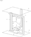
- FIG. 1 is a perspective view showing a bending test facility for a metal sheet material for an automobile body according to the embodiment of the present invention and a bending test method for a metal sheet material for an automobile body according to the embodiment of the present invention, which uses the bending test facility.
- the bending test method for a metal sheet material for an automobile body includes performing a bending test using the bending test facility according to the foregoing embodiment, in which the slide S is displaced in such a direction as to approach the fixed table T of the above-described tester to cause the punch 4 to press a center between the above-described two supported portions of the test specimen P from the opposite side to the dies 2, namely, downward from above in FIG. 1 , so that the test specimen P is pressed into a V-shaped gap between the two dies 2 and bent to be deformed in a V shape, and photographing a bending outside surface of the test specimen P during the bending test, which faces downward in FIG. 1 , by use of the camera 5 from below through the gap between the two dies 2 below the test specimen P.
- the bending outside surface of the test specimen P is photographed from the side of the dies 2 by use of the camera 5 having a fixed relative positional relationship with the punch 4, and thus a strain state of the bending outside surface of the test specimen P can be photographed without falling out of focus during the test.
- an embodiment of the bending performance evaluation method includes evaluating bending performance of the test specimen P by inputting, to an ordinary computer, an image of a strain state of the bending outside surface of the test specimen P photographed from the side of the dies 2 during the bending test of the test specimen P using the bending test method according to the foregoing embodiment and by analyzing, with an evaluation program executed by the computer, such as the digital image correlation (DIC), at least one of different types of information including a distribution of strain on the bending outside of the test specimen P, a change in the distribution, the occurrence and development of a crack thereon, and a distribution of cracks thereon.
- DIC digital image correlation
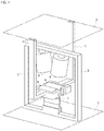
- FIG. 2 is a perspective view showing a bending test facility for a metal sheet material for an automobile body according to another embodiment of the present invention and a bending test method for a metal sheet material for an automobile body according to the other embodiment of the present invention, which uses the bending test facility.
- the bending test method for a metal sheet material for an automobile body includes performing a bending test, using the bending test facility according to the foregoing embodiment, in which the slide S is displaced in such a direction as to approach the fixed table T of the above-described tester to cause the punch 7 to press the center between the above-described two supported portions of the test specimen P from the side opposite to the side of the rollers 6, namely, downward from above in FIG. 2 , so that the test specimen P is pressed into the gap between the two rollers 6 and bent at an acute angle to be deformed, and photographing a bending outside surface of the test specimen P during the bending test, which faces downward in FIG. 1 , by use of the camera 5 from below through the gap between the two rollers 6 below the test specimen P.
- the bending outside surface of the test specimen P is photographed from the side of the rollers 6 by use of the camera 5 having a fixed relative positional relationship with the punch 7, and thus while, for example, the VDA 238-100 bending test is performed, a strain state of the bending outside surface of the test specimen P can be photographed without falling out of focus during the test.
- another embodiment of the bending performance evaluation method includes evaluating bending performance of the test specimen P by inputting, to an ordinary computer, an image of a strain state of the bending outside surface of the test specimen P photographed from the side of the rollers 6 during the bending test of the test specimen P using the bending test method according to the foregoing embodiment and by analyzing, with an evaluation program executed by the computer, such as the digital image correlation (DIC), at least one of different types of information including a distribution of strain on the bending outside of the test specimen P, a change in the distribution, the occurrence and development of a crack thereon, and a distribution of cracks thereon.
- DIC digital image correlation
- FIG. 3 is a perspective view showing a modification example of the bending test facility for a metal sheet material for an automobile body according to the embodiment shown in FIG. 1 and a modification example of the bending test method for a metal sheet material for an automobile body according to the embodiment shown in FIG. 1 , which uses the bending test facility.
- a bending test facility for a metal sheet material for an automobile body according to this modification example is arranged upside down with respect to the bending test facility according to the embodiment shown in FIG. 1 and has the following configuration. That is, two dies 2 as a supporting member are fixed via a support frame 1 to a slide S as a movable portion of the above-described tester, a mounting plane of which is shown by a virtual line in FIG. 3 , with a gap provided therebetween and support, with the aid of unshown sponge or the like, two supported portions of a flat and rectangular test specimen P in vicinities of both ends thereof, which is formed of a metal sheet material for an automobile body.
- a punch 4 having a V-shaped cross section is fixed via a connection frame 3 to a fixed table T as an immovable portion of the above-described tester, a mounting plane of which is shown by another virtual line in FIG. 3 .
- a camera 5 has a relative positional relationship with the punch 4 fixed by the connection frame 3 and includes a lens directed to a gap between the two dies 2.
- a bending test method for a metal sheet material for an automobile body includes, using the bending test facility according to the foregoing modification example, performing a bending test in which the slide S is displaced in such a direction as to approach the fixed table T of the above-described tester to cause the punch 4 to press a center between the above-described two supported portions of the test specimen P from a side opposite to a side of the dies 2, namely, upward from below in FIG. 3 , so that the test specimen P is pressed into a V-shaped gap between the two dies 2 and bent to be deformed in a V shape, and photographing a bending outside surface of the test specimen P during the bending test, which faces upward in FIG. 3 , by use of the camera 5 from above through the gap between the two dies 2 above the test specimen P.
- the bending outside surface of the test specimen P is photographed from the side of the dies 2 by use of the camera 5 having a fixed relative positional relationship with the punch 4, and thus a strain state of the bending outside surface of the test specimen P can be photographed without falling out of focus during the test.
- the punch 4 and the camera 5 are fixed to the fixed table T as the immovable portion, the punch 4 and the camera 5 can be made less affected by vibrations or the like caused by displacement of the slide S during the bending test, and work to install a fixing jig, wiring, and so on for the punch 4 and the camera 5 can be more facilitated.
- a bending performance evaluation method includes evaluating bending performance of the test specimen P by inputting, to an ordinary computer, an image of a strain state of the bending outside surface of the test specimen P photographed from the side of the dies 2 during the bending test of the test specimen P using the bending test method according to the modification example shown in FIG. 3 and by analyzing, with an evaluation program executed by the computer, such as the digital image correlation (DIC), at least one of different types of information including a distribution of strain on a bending outside of the test specimen P, a change in the distribution, the occurrence and development of a crack thereon, and a distribution of cracks thereon.
- DIC digital image correlation
- FIG. 4 is a perspective view showing a modification example of the bending test facility for a metal sheet material for an automobile body according to the embodiment shown in FIG. 2 and a modification example of the bending test method for a metal sheet material for an automobile body according to the embodiment shown in FIG. 2 , which uses the bending test facility.
- a bending test facility for a metal sheet material for an automobile body according to this modification example is arranged upside down with respect to the bending test facility according to the embodiment shown in FIG. 2 and has the following configuration. That is, two rollers 6 as a supporting member are arranged in parallel and horizontally with a gap provided therebetween and rotatably and axially supported via a support frame 1 to a slide S as a movable portion of the above-described tester, a mounting plane of which is shown by a virtual line in FIG. 4 , and support, with the aid of unshown sponge or the like, two supported portions of a flat and rectangular test specimen P in vicinities of both ends thereof, which is formed of a metal sheet material for an automobile body.
- a sharply edged punch 7 is fixed via a connection frame 3 to a fixed table T as an immovable portion of the above-described tester, a mounting plane of which is shown by another virtual line in FIG. 4 .
- a camera 5 has a fixed relative positional relationship with the punch 7 by the connection frame 3 and includes a lens directed to a gap between the two rollers 6.
- a bending test method for a metal sheet material for an automobile body includes, using the bending test facility according to the foregoing modification example, performing a bending test in which the slide S is displaced in such a direction as to approach the fixed table T of the above-described tester to cause the punch 7 to press a center between the above-described two supported portions of the test specimen P from the opposite side to the rollers 6, namely, upward from below in FIG. 4 , so that the test specimen P is pressed into the gap between the two rollers 6 and bent at an acute angle to be deformed, and photographing a bending outside surface of the test specimen P during the bending test, which faces upward in FIG. 4 , by use of the camera 5 from above through the gap between the two rollers 6 above the test specimen P.
- the bending outside surface of the test specimen P is photographed from the side of the rollers 6 by use of the camera 5 having a fixed relative positional relationship with the punch 7, and thus while, for example, the VDA 238-100 bending test is performed, a strain state of the bending outside surface of the test specimen P can be photographed without falling out of focus during the test.
- the punch 7 and the camera 5 are fixed to the fixed table T as the immovable portion, the punch 7 and the camera 5 can be made less affected by vibrations or the like caused by displacement of the slide S during the bending test, and work to install a fixing jig, wiring, and so on for the punch 7 and the camera 5 can be more facilitated.
- a bending performance evaluation method includes evaluating bending performance of the test specimen P by inputting, to an ordinary computer, an image of a strain state of the bending outside surface of the test specimen P photographed from the side of the rollers 6 during the bending test of the test specimen P using the bending test method according to the modification example shown in FIG. 4 and by analyzing, with an evaluation program executed by the computer, such as the digital image correlation (DIC), at least one of different types of information including a distribution of strain on a bending outside of the test specimen P, a change in the distribution, the occurrence and development of a crack thereon, and a distribution of cracks thereon.
- DIC digital image correlation
- FIG. 5 is a perspective view showing another modification example of the bending test facility for a metal sheet material for an automobile body according to the embodiment shown in FIG. 2 and another modification example of the bending test method for a metal sheet material for an automobile body according to the embodiment shown in FIG. 2 , which uses the bending test facility.
- a bending test facility for a metal sheet material for an automobile body according to this modification example, at least one of the two ordinary cylindrical rollers 6 in the bending test facility shown in FIG. 4 , which is the modification example of the bending test facility according to the embodiment shown in FIG. 2 , or two rollers 6 in an illustrated example are each replaced with a semicircular roller 8 having, while including a rotary shaft portion, a partially missing circular cross section as viewed from a rotary shaft direction thereof, and other components are configured similarly to those in the bending test facility shown in FIG. 4 .
- a bending test method for a metal sheet material for an automobile body includes, using the bending test facility according to the foregoing modification example, performing a bending test in which the slide S is displaced in such a direction as to approach the fixed table T of the above-described tester to cause the punch 7 to press a center between the above-described two supported portions of the test specimen P from the opposite side to the semicircular rollers 8, namely, upward from below in FIG. 5 , so that the test specimen P is pressed into a gap between the two semicircular rollers 8 and bent at an acute angle to be deformed, and photographing a bending outside surface of the test specimen P during the bending test, which faces upward in FIG. 5 , by use of the camera 5 from above through the gap between the two semicircular rollers 8 above the test specimen P.
- the bending outside surface of the test specimen P is photographed from the side of the semicircular rollers 8 by use of the camera 5 having a fixed relative positional relationship with the punch 7, and thus while, for example, the VDA 238-100 bending test is performed, a strain state of the bending outside surface of the test specimen P can be photographed without falling out of focus during the test.
- the punch 7 and the camera 5 are fixed to the fixed table T as the immovable portion, the punch 7 and the camera 5 can be made less affected by vibrations or the like caused by displacement of the slide S during the bending test, and work to install a fixing jig, wiring, and so on for the punch 7 and the camera 5 can be more facilitated. Moreover, it is possible to photograph, by use of the camera 5, the bending outside surface of the test specimen P from the side of the semicircular rollers 8 while securing a field of view and a luminosity through omitted parts of the semicircular rollers 8 and thus to obtain a clearer image.
- a bending performance evaluation method includes evaluating bending performance of the test specimen P by inputting, to an ordinary computer, a clearer image of the strain state of the bending outside surface of the test specimen P photographed from the side of the semicircular rollers 8 during the bending test of the test specimen P using the bending test method according to the modification example shown in FIG. 5 and by analyzing, with an evaluation program executed by the computer, such as the digital image correlation (DIC), at least one of different types of information including a distribution of strain on a bending outside of the test specimen P, a change in the distribution, the occurrence and development of a crack thereon, and a distribution of cracks thereon.
- DIC digital image correlation
- a single die having an opening at a center thereof may be used to support the two supported portions of the test specimen P in vicinities of both ends thereof.
- the camera 5 for example, a single-lens reflex type film camera, a single-lens reflex type digital camera, or the like can be used, and the camera 5 is provided beforehand with a remote shutter so as to be capable of photographing at any timing.
- the number of cameras 5 used is determined depending on how the cameras 5 are used, i.e., for example, in a case where there are a large number of spots to be photographed or in a case where photographed images are to be subjected to three-dimensional DIC analysis, two cameras 5 are installed as shown in FIG. 1 to FIG. 5 or there is adopted a structure enabling the use of two or more cameras 5 Moreover, in consideration of a size of an image desired to be photographed or dimensions of a tester, preferably, a camera including a lens or an imaging device having a resolution as high as possible is used as the camera 5.
- the bending test facility and the bending test method according to the modification example shown in FIG. 4 were used to perform a bending test pursuant to the VDA 238-100 standard and to photograph an image of a bending outside of the test specimen P during the bending test.
- As the test specimen P there were used three types of materials A, B, and C of 50 mm square each obtained by shearing a sheet material formed of a high-strength steel sheet for an automobile body and then grinding an end face thereof.
- a distance between the two rollers 6 was set to a value given by a thickness of the test specimen P ⁇ 2 + 0.5 mm, and a radius of a distal end of the punch 7 was set to 0.4 mm.
- the test specimen P placed between the punch 7 and the rollers 6 was bent to be deformed by the rollers 6 fixed to the slide S as the movable portion of the tester and the punch 7 fixed to the fixed table T as the immovable portion of the tester.
- a punch speed was set to 5 mm/min.
- a load applied to the slide S and s stroke (a displacement amount) of the slide S during this process were measured to output a load-stroke curve.
- the above-described load-stroke curve was such that the load rose as soon as bending deformation started, at a given deformation stroke, fracture occurred at a location of the bending deformation and a maximum load was exhibited, and then the load was decreased.
- the above-described deformation stroke at which the maximum load was exhibited is defined as a fracture stroke.
- the two single-lens reflex type cameras 5 were adjusted to be disposed at such respective positions that they were capable of photographing the bending outside of the test specimen P through between the two rollers 6 and were fixed to the fixed table T as the immovable portion of the tester.
- the bending test was started to start bending deformation, continuous photographing by use of the cameras 5 was started as soon as the load rose, and a photographing speed was set to one photograph per second.
- the above-described bending test was ended at appropriate timing after the load had been decreased due to the occurrence of fracture in the test specimen P.
- the three-dimensional DIC analysis was applied to a sequence of photographs taken by the above-described method to analyze an amount of strain on the bending outside of the test specimen P when strain in the test specimen P in a flat sheet state before the test was assumed to be 0, and an amount of strain on the bending outside of the test specimen P at the above-described fracture stroke was determined.
- the above-described amount of strain is defined as corresponding to fracture strain.
- FIG. 6 shows images obtained by photographing a strain state of each of the materials at the occurrence of fracture strain.
- Table 1 shows material properties of the materials, fracture strokes thereof, and fracture strain therein.
- the bending test facility and method according to the modification example shown in FIG. 4 are used to perform the bending test pursuant to the VDA 238-100 standard, instead, the bending test facility and the bending test method according to any of the other embodiments and modification examples can also be used.
- two supported portions of a flat test specimen formed of the metal sheet material for an automobile body are supported with a supporting member, and a bending test is performed in which an area between the two supported portions of the test specimen is pressed by use of a punch from a side opposite to a side of the supporting member so that the test specimen is bent to be deformed, during which a bending outside surface of the test specimen is photographed from a side of the supported portions by use of a camera having a fixed relative positional relationship with the punch.
- a strain state of the bending outside surface of the test specimen can be photographed without falling out of focus during the test.
- bending performance of a test specimen is evaluated based on information on a distribution of strain on a bending outside of the test specimen, a change in the distribution, the occurrence and development of a crack thereon, and/or a distribution of cracks thereon obtained from an image of the bending outside of the test specimen photographed by use of the camera during the bending test using the bending test facility.
- information on a distribution of strain on a bending outside of the test specimen is evaluated based on information on a distribution of strain on a bending outside of the test specimen, a change in the distribution, the occurrence and development of a crack thereon, and/or a distribution of cracks thereon obtained from an image of the bending outside of the test specimen photographed by use of the camera during the bending test using the bending test facility.
Landscapes
- Physics & Mathematics (AREA)
- Health & Medical Sciences (AREA)
- Life Sciences & Earth Sciences (AREA)
- Chemical & Material Sciences (AREA)
- Analytical Chemistry (AREA)
- Biochemistry (AREA)
- General Health & Medical Sciences (AREA)
- General Physics & Mathematics (AREA)
- Immunology (AREA)
- Pathology (AREA)
- Investigating Strength Of Materials By Application Of Mechanical Stress (AREA)
Abstract
Description
- The present invention relates to a bending test facility and a bending test method for a metal sheet material for an automobile body and a bending performance evaluation method using the bending test facility.
- With the recent increase in use of high-strength steel sheets as a material for an automobile body to achieve a weight reduction of an automobile while maintaining collision performance thereof, an increase in strength of the material leads to a decrease in ductility of the material, resulting in a higher risk of the occurrence of fracture in a collision.
- In particular, an energy absorbing member that is arranged at each of a front and a rear of an automobile body is desired to be plastically deformed in a collision so as to absorb collision energy. When axially collapsed, however, the energy absorbing member often suffers from local formation of large strain, which leads to the occurrence of fracture. When such fracture develops into a large crack to cause disintegration of the member, there may occur a substantial decrease in collision load, rendering energy absorbing performance unstable, and the unstable energy absorbing performance has been a serious hindrance to the use of a high-strength steel sheet in an automobile body.
- It is known that the above-described fracture due to axial collapse deformation cannot be evaluated using an index such as uniform elongation or local elongation obtained by a tension test, and for determination of presence or absence of the fracture, various material test methods have conventionally been proposed.
- For example, a VDA 238-100 bending test method standardized by the German Association of the Automobile Industry Standard and Rules (Verband der Automobilindustrie: VDA) proposes a method in which a sheet material is laid over two rollers arranged side by side and is pressed from above by use of a sharp punch so as to be bent, and a limit bending radius of the sheet material is evaluated. It is reported that the limit bending radius obtained by this method corresponds to local deformation that might occur in a collision.
- Further,
Patent Literature 1 proposes to improve the above-described bending test method pursuant to the VDA standard so that resistance of a part to a crack in a collision is predicted by evaluating, from a load stroke curve obtained by an experiment, a status of the occurrence of cracking after the limit bending radius has been reached. - The above-described prior-art evaluation test can evaluate the superiority or inferiority in terms of a fracture resistance property at the occurrence of axial collapse for each material. This evaluation test also involves not only measurement of a punch load and a stroke in a bending test but also observation of a strain state of the material during the test and thus can provide, in addition to information related to a macro fracture phenomenon, information extremely useful in developing materials excellent in fracture resistance property, such as information on how strain develops into local fracture or information on critical fracture strain.
- Patent Literature 1:
JP-A-2016-080464 - However, since a bending test is typically performed while a punch is operated, a strain state of a bending outside surface can hardly be photographed without a camera going out of focus during the test. Furthermore, when the bending test pursuant to the VDA standard is used to perform an evaluation, in order to photograph a bending outside surface by use of a camera, it is required that the surface of a sample be photographed at a high resolution through a gap between the two rollers, in which case a luminosity and a field of view of the sample can hardly be secured.
- In view of the above, it is an object of the present invention to provide a bending test facility and a bending test method for a metal sheet material for an automobile body and a bending performance evaluation method using the bending test facility, which advantageously solve the above-described problems with the conventional test methods.
- A bending test facility for a metal sheet material for an automobile body according to the present invention that achieves the above-described object is characterized by including
- a supporting member that supports two supported portions of a flat test specimen formed of the metal sheet material for an automobile body;
- a punch for performing a bending test in which an area between the two supported portions of the test specimen is pressed from the opposite side to the supporting member so that the test specimen is bent to be deformed; and
- a camera for photographing, from the side of the supporting member, a bending outside surface of the test specimen during the bending test using the punch,
- wherein relative positions of the punch and the camera during the bending test are fixed.
- Furthermore, a bending test method for a metal sheet material for an automobile body according to the present invention that achieves the above-described object is characterized by including:
- supporting two supported portions of a flat test specimen formed of the metal sheet material for an automobile body with a supporting member; and
- performing a bending test in which an area between the two supported portions of the test specimen is pressed by use of a punch from the opposite side to the supporting member so that the test specimen is bent to be deformed,
- wherein during the bending test, a bending outside surface of the test specimen is photographed from the side of the supported portions by use of a camera having a fixed relative positional relationship with the punch.
- Moreover, a bending performance evaluation method for a metal sheet material for an automobile body according to the present invention is characterized by including, during a bending test using the bending test facility, photographing an image of a bending outside of the test specimen by use of the camera, obtaining, from the image, information on a distribution of strain on the bending outside of the test specimen, a change in the distribution, the occurrence and development of a crack thereon, and/or a distribution of cracks thereon, and evaluating bending performance of the test specimen based on the information.
- According to the bending test facility and the bending test method for a metal sheet material for an automobile body of the present invention, two supported portions of a flat test specimen formed of the metal sheet material for an automobile body are supported with a supporting member, and a bending test is performed in which an area between the two supported portions of the test specimen is pressed by use of a punch from the opposite side to the supporting member so that the test specimen is bent to be deformed, during which a bending outside surface of the test specimen is photographed from the side of the supported portions by use of a camera having a fixed relative positional relationship with the punch. Thus, a strain state of the bending outside surface of the test specimen can be photographed without falling out of focus during the test.
- Further, according to the bending performance evaluation method of the present invention, bending performance of a test specimen is evaluated based on information on a distribution of strain on a bending outside of the test specimen, a change in the distribution, the occurrence and development of a crack thereon, and/or a distribution of cracks thereon obtained from an image of the bending outside of the test specimen photographed by use of the camera during the bending test using the bending test facility. Thus, it is possible to obtain, in addition to information related to a macro fracture phenomenon, information extremely useful in developing materials excellent in fracture resistance property, such as information on how strain develops into local fracture or information on critical fracture strain.
- In the bending test facility and the bending test method according to the present invention, the supporting member supporting the two supported portions of the test specimen may be formed of two rollers arranged in parallel and horizontally at a distance from each other. With this configuration, it is possible to implement the bending test method prescribed in the VDA 238-100 standard.
- Further, in the bending test facility and the bending test method according to the present invention, at least one of the two rollers may have, while including a rotary shaft portion, a partially missing circular cross section as viewed from a rotary shaft direction thereof. With this configuration, it is possible to photograph, by use of the camera, the bending outside surface of the test specimen from the side of the supported portions while securing a field of view and a luminosity through an omitted part(s) of the roller(s) and thus to obtain a clearer image.
- Moreover, the bending test facility and the bending test method according to the present invention may have a configuration including a tester that includes a movable portion and an immovable portion and advances or retracts the movable portion relative to the immovable portion, in which the punch and the camera are installed in the immovable portion, and the supporting member is installed in the movable portion. With this configuration, the punch and the camera are not affected by vibrations or the like caused by movement of the movable portion with respect to the immovable portion during a bending test, and thus it is possible to more reliably prevent the camera from going out of focus.
- Moreover, in the bending performance evaluation method according to the present invention, the information may be obtained by digital image correlation (DIC). With this configuration, a more detailed bending performance evaluation can be performed.
-
-
FIG. 1 is a perspective view showing a bending test facility for a metal sheet material for an automobile body according to an embodiment of the present invention and a bending test method for a metal sheet material for an automobile body according to the embodiment of the present invention, which uses the bending test facility. -
FIG. 2 is a perspective view showing a bending test facility for a metal sheet material for an automobile body according to another embodiment of the present invention and a bending test method for a metal sheet material for an automobile body according to the other embodiment of the present invention, which uses the bending test facility. -
FIG. 3 is a perspective view showing a modification example of the bending test facility for a metal sheet material for an automobile body according to the embodiment shown inFIG. 1 and a modification example of the bending test method for a metal sheet material for an automobile body according to the embodiment shown inFIG. 1 , which uses the bending test facility. -
FIG. 4 is a perspective view showing a modification example of the bending test facility for a metal sheet material for an automobile body according to the embodiment shown inFIG. 2 and a modification example of the bending test method for a metal sheet material for an automobile body according to the embodiment shown inFIG. 2 , which uses the bending test facility. -
FIG. 5 is a perspective view showing another modification example of the bending test facility for a metal sheet material for an automobile body according to the embodiment shown inFIG. 2 and another modification example of the bending test method for a metal sheet material for an automobile body according to the embodiment shown inFIG. 2 , which uses the bending test facility. -
FIG. 6 is a photograph showing images of materials at the occurrence of fracture strain photographed in the bending test method for a metal sheet material for an automobile body according to the modification example shown inFIG. 4 , which uses the bending test facility for a metal sheet material for an automobile body according to the modification example shown inFIG. 4 . - An embodiment of the present invention will be described with reference to the appended drawings. Note that
FIG. 1 is a perspective view showing a bending test facility for a metal sheet material for an automobile body according to the embodiment of the present invention and a bending test method for a metal sheet material for an automobile body according to the embodiment of the present invention, which uses the bending test facility. - The bending test facility for a metal sheet material for an automobile body according to this embodiment includes
- two
dies 2 that are fixed via asupport frame 1 with a gap provided therebetween to a fixed table T as an immovable portion, a mounting plane of which is shown by a virtual line inFIG. 1 , of a tester such as, for example, an Amsler-type tester that measures, while applying a load to an object to be tested by use of a slide configured to be displaced in such a direction as to approach or separate from a fixed table, a magnitude of the load and a displacement amount of the slide and that function as a supporting member that supports two supported portions in the vicinity of both ends of a flat and rectangular test specimen P formed of a metal sheet material for an automobile body, - a
punch 4 that has a V-shaped cross section and is fixed via aconnection frame 3 to a slide S as a movable portion of the above-described tester, a mounting plane of which is shown by a virtual line inFIG. 1 , and - a
camera 5 that has a relative positional relation to thepunch 4 by theconnection frame 3 and includes a lens directed to the gap between the twodies 2. - Furthermore, the bending test method for a metal sheet material for an automobile body according to this embodiment includes performing a bending test using the bending test facility according to the foregoing embodiment, in which the slide S is displaced in such a direction as to approach the fixed table T of the above-described tester to cause the
punch 4 to press a center between the above-described two supported portions of the test specimen P from the opposite side to thedies 2, namely, downward from above inFIG. 1 , so that the test specimen P is pressed into a V-shaped gap between the twodies 2 and bent to be deformed in a V shape, and photographing a bending outside surface of the test specimen P during the bending test, which faces downward inFIG. 1 , by use of thecamera 5 from below through the gap between the twodies 2 below the test specimen P. - According to the bending test facility and the bending test method for a metal sheet material for an automobile body of such an embodiment, during the bending test of the test specimen P, the bending outside surface of the test specimen P is photographed from the side of the
dies 2 by use of thecamera 5 having a fixed relative positional relationship with thepunch 4, and thus a strain state of the bending outside surface of the test specimen P can be photographed without falling out of focus during the test. - Further, an embodiment of the bending performance evaluation method according to the present invention includes evaluating bending performance of the test specimen P by inputting, to an ordinary computer, an image of a strain state of the bending outside surface of the test specimen P photographed from the side of the
dies 2 during the bending test of the test specimen P using the bending test method according to the foregoing embodiment and by analyzing, with an evaluation program executed by the computer, such as the digital image correlation (DIC), at least one of different types of information including a distribution of strain on the bending outside of the test specimen P, a change in the distribution, the occurrence and development of a crack thereon, and a distribution of cracks thereon. According to the bending performance evaluation method of this embodiment, it is possible to obtain, in addition to information related to a macro fracture phenomenon, information extremely useful in developing materials excellent in fracture resistance property, such as information on how strain develops into local fracture or information on critical fracture strain. -
FIG. 2 is a perspective view showing a bending test facility for a metal sheet material for an automobile body according to another embodiment of the present invention and a bending test method for a metal sheet material for an automobile body according to the other embodiment of the present invention, which uses the bending test facility. - The bending test facility for a metal sheet material for an automobile body according to this embodiment includes:
- two
rollers 6 that are arranged in parallel and horizontally with a gap provided therebetween and rotatably and axially supported via asupport frame 1 to a fixed table T as an immovable portion of the above-described tester, a mounting plane of which is shown by a virtual line inFIG. 2 , and function as a supporting member that supports two supported portions of a flat and rectangular test specimen P in vicinities of both ends thereof, which is formed of a metal sheet material for an automobile body; - a sharply
edged punch 7 that is fixed via aconnection frame 3 to a slide S as a movable portion of the above-described tester, a mounting plane of which is shown by another virtual line inFIG. 2 , and is used to perform a bending test in which thepunch 7 presses a center between the above-described two supported portions of the test specimen P from a side opposite to therollers 6, namely, downward from above inFIG. 2 , so that the test specimen P is bent at an acute angle to be deformed; and - a
camera 5 that has a fixed relative positional relationship with thepunch 7 by theconnection frame 3 and includes a lens directed to the gap between the tworollers 6. - Furthermore, the bending test method for a metal sheet material for an automobile body according to this embodiment includes performing a bending test, using the bending test facility according to the foregoing embodiment, in which the slide S is displaced in such a direction as to approach the fixed table T of the above-described tester to cause the
punch 7 to press the center between the above-described two supported portions of the test specimen P from the side opposite to the side of therollers 6, namely, downward from above inFIG. 2 , so that the test specimen P is pressed into the gap between the tworollers 6 and bent at an acute angle to be deformed, and photographing a bending outside surface of the test specimen P during the bending test, which faces downward inFIG. 1 , by use of thecamera 5 from below through the gap between the tworollers 6 below the test specimen P. - According to the bending test facility and the bending test method for a metal sheet material for an automobile body of such an embodiment, during the bending test of the test specimen P, the bending outside surface of the test specimen P is photographed from the side of the
rollers 6 by use of thecamera 5 having a fixed relative positional relationship with thepunch 7, and thus while, for example, the VDA 238-100 bending test is performed, a strain state of the bending outside surface of the test specimen P can be photographed without falling out of focus during the test. - Further, another embodiment of the bending performance evaluation method according to the present invention includes evaluating bending performance of the test specimen P by inputting, to an ordinary computer, an image of a strain state of the bending outside surface of the test specimen P photographed from the side of the
rollers 6 during the bending test of the test specimen P using the bending test method according to the foregoing embodiment and by analyzing, with an evaluation program executed by the computer, such as the digital image correlation (DIC), at least one of different types of information including a distribution of strain on the bending outside of the test specimen P, a change in the distribution, the occurrence and development of a crack thereon, and a distribution of cracks thereon. According to the bending performance evaluation method of this embodiment, in the VDA 238-100 bending test, it is possible to obtain, in addition to information related to a macro fracture phenomenon, information such as on how strain develops into local fracture or on critical fracture strain. -
FIG. 3 is a perspective view showing a modification example of the bending test facility for a metal sheet material for an automobile body according to the embodiment shown inFIG. 1 and a modification example of the bending test method for a metal sheet material for an automobile body according to the embodiment shown inFIG. 1 , which uses the bending test facility. - A bending test facility for a metal sheet material for an automobile body according to this modification example is arranged upside down with respect to the bending test facility according to the embodiment shown in
FIG. 1 and has the following configuration. That is, two dies 2 as a supporting member are fixed via asupport frame 1 to a slide S as a movable portion of the above-described tester, a mounting plane of which is shown by a virtual line inFIG. 3 , with a gap provided therebetween and support, with the aid of unshown sponge or the like, two supported portions of a flat and rectangular test specimen P in vicinities of both ends thereof, which is formed of a metal sheet material for an automobile body. Apunch 4 having a V-shaped cross section is fixed via aconnection frame 3 to a fixed table T as an immovable portion of the above-described tester, a mounting plane of which is shown by another virtual line inFIG. 3 . Acamera 5 has a relative positional relationship with thepunch 4 fixed by theconnection frame 3 and includes a lens directed to a gap between the two dies 2. - Furthermore, a bending test method for a metal sheet material for an automobile body according to this modification example includes, using the bending test facility according to the foregoing modification example, performing a bending test in which the slide S is displaced in such a direction as to approach the fixed table T of the above-described tester to cause the
punch 4 to press a center between the above-described two supported portions of the test specimen P from a side opposite to a side of the dies 2, namely, upward from below inFIG. 3 , so that the test specimen P is pressed into a V-shaped gap between the two dies 2 and bent to be deformed in a V shape, and photographing a bending outside surface of the test specimen P during the bending test, which faces upward inFIG. 3 , by use of thecamera 5 from above through the gap between the two dies 2 above the test specimen P. - According to the bending test facility and the bending test method for a metal sheet material for an automobile body of such a modification example, during the bending test of the test specimen P, the bending outside surface of the test specimen P is photographed from the side of the dies 2 by use of the
camera 5 having a fixed relative positional relationship with thepunch 4, and thus a strain state of the bending outside surface of the test specimen P can be photographed without falling out of focus during the test. Moreover, since thepunch 4 and thecamera 5 are fixed to the fixed table T as the immovable portion, thepunch 4 and thecamera 5 can be made less affected by vibrations or the like caused by displacement of the slide S during the bending test, and work to install a fixing jig, wiring, and so on for thepunch 4 and thecamera 5 can be more facilitated. - Further, a bending performance evaluation method according to the modification example of the embodiment of the present invention includes evaluating bending performance of the test specimen P by inputting, to an ordinary computer, an image of a strain state of the bending outside surface of the test specimen P photographed from the side of the dies 2 during the bending test of the test specimen P using the bending test method according to the modification example shown in
FIG. 3 and by analyzing, with an evaluation program executed by the computer, such as the digital image correlation (DIC), at least one of different types of information including a distribution of strain on a bending outside of the test specimen P, a change in the distribution, the occurrence and development of a crack thereon, and a distribution of cracks thereon. According also to the bending performance evaluation method of this embodiment, it is possible to obtain, in addition to information related to a macro fracture phenomenon, information extremely useful in developing materials excellent in fracture resistance property, such as information on how strain develops into local fracture or information on critical fracture strain. -
FIG. 4 is a perspective view showing a modification example of the bending test facility for a metal sheet material for an automobile body according to the embodiment shown inFIG. 2 and a modification example of the bending test method for a metal sheet material for an automobile body according to the embodiment shown inFIG. 2 , which uses the bending test facility. - A bending test facility for a metal sheet material for an automobile body according to this modification example is arranged upside down with respect to the bending test facility according to the embodiment shown in
FIG. 2 and has the following configuration. That is, tworollers 6 as a supporting member are arranged in parallel and horizontally with a gap provided therebetween and rotatably and axially supported via asupport frame 1 to a slide S as a movable portion of the above-described tester, a mounting plane of which is shown by a virtual line inFIG. 4 , and support, with the aid of unshown sponge or the like, two supported portions of a flat and rectangular test specimen P in vicinities of both ends thereof, which is formed of a metal sheet material for an automobile body. A sharply edgedpunch 7 is fixed via aconnection frame 3 to a fixed table T as an immovable portion of the above-described tester, a mounting plane of which is shown by another virtual line inFIG. 4 . Acamera 5 has a fixed relative positional relationship with thepunch 7 by theconnection frame 3 and includes a lens directed to a gap between the tworollers 6. - Furthermore, a bending test method for a metal sheet material for an automobile body according to this modification example includes, using the bending test facility according to the foregoing modification example, performing a bending test in which the slide S is displaced in such a direction as to approach the fixed table T of the above-described tester to cause the
punch 7 to press a center between the above-described two supported portions of the test specimen P from the opposite side to therollers 6, namely, upward from below inFIG. 4 , so that the test specimen P is pressed into the gap between the tworollers 6 and bent at an acute angle to be deformed, and photographing a bending outside surface of the test specimen P during the bending test, which faces upward inFIG. 4 , by use of thecamera 5 from above through the gap between the tworollers 6 above the test specimen P. - According also to the bending test facility and the bending test method for a metal sheet material for an automobile body of such a modification example, during the bending test of the test specimen P, the bending outside surface of the test specimen P is photographed from the side of the
rollers 6 by use of thecamera 5 having a fixed relative positional relationship with thepunch 7, and thus while, for example, the VDA 238-100 bending test is performed, a strain state of the bending outside surface of the test specimen P can be photographed without falling out of focus during the test. Moreover, since thepunch 7 and thecamera 5 are fixed to the fixed table T as the immovable portion, thepunch 7 and thecamera 5 can be made less affected by vibrations or the like caused by displacement of the slide S during the bending test, and work to install a fixing jig, wiring, and so on for thepunch 7 and thecamera 5 can be more facilitated. - Further, a bending performance evaluation method according to another modification example of the embodiment of the present invention includes evaluating bending performance of the test specimen P by inputting, to an ordinary computer, an image of a strain state of the bending outside surface of the test specimen P photographed from the side of the
rollers 6 during the bending test of the test specimen P using the bending test method according to the modification example shown inFIG. 4 and by analyzing, with an evaluation program executed by the computer, such as the digital image correlation (DIC), at least one of different types of information including a distribution of strain on a bending outside of the test specimen P, a change in the distribution, the occurrence and development of a crack thereon, and a distribution of cracks thereon. According also to the bending performance evaluation method according to this modification example, it is possible to obtain, in addition to information related to a macro fracture phenomenon, information extremely useful in developing materials excellent in fracture resistance property, such as information on how strain develops into local fracture or information on critical fracture strain. -
FIG. 5 is a perspective view showing another modification example of the bending test facility for a metal sheet material for an automobile body according to the embodiment shown inFIG. 2 and another modification example of the bending test method for a metal sheet material for an automobile body according to the embodiment shown inFIG. 2 , which uses the bending test facility. - In a bending test facility for a metal sheet material for an automobile body according to this modification example, at least one of the two ordinary
cylindrical rollers 6 in the bending test facility shown inFIG. 4 , which is the modification example of the bending test facility according to the embodiment shown inFIG. 2 , or tworollers 6 in an illustrated example are each replaced with asemicircular roller 8 having, while including a rotary shaft portion, a partially missing circular cross section as viewed from a rotary shaft direction thereof, and other components are configured similarly to those in the bending test facility shown inFIG. 4 . - Furthermore, a bending test method for a metal sheet material for an automobile body according to this modification example includes, using the bending test facility according to the foregoing modification example, performing a bending test in which the slide S is displaced in such a direction as to approach the fixed table T of the above-described tester to cause the
punch 7 to press a center between the above-described two supported portions of the test specimen P from the opposite side to thesemicircular rollers 8, namely, upward from below inFIG. 5 , so that the test specimen P is pressed into a gap between the twosemicircular rollers 8 and bent at an acute angle to be deformed, and photographing a bending outside surface of the test specimen P during the bending test, which faces upward inFIG. 5 , by use of thecamera 5 from above through the gap between the twosemicircular rollers 8 above the test specimen P. - According also to the bending test facility and the bending test method for a metal sheet material for an automobile body of such a modification example, during the bending test of the test specimen P, the bending outside surface of the test specimen P is photographed from the side of the
semicircular rollers 8 by use of thecamera 5 having a fixed relative positional relationship with thepunch 7, and thus while, for example, the VDA 238-100 bending test is performed, a strain state of the bending outside surface of the test specimen P can be photographed without falling out of focus during the test. Since thepunch 7 and thecamera 5 are fixed to the fixed table T as the immovable portion, thepunch 7 and thecamera 5 can be made less affected by vibrations or the like caused by displacement of the slide S during the bending test, and work to install a fixing jig, wiring, and so on for thepunch 7 and thecamera 5 can be more facilitated. Moreover, it is possible to photograph, by use of thecamera 5, the bending outside surface of the test specimen P from the side of thesemicircular rollers 8 while securing a field of view and a luminosity through omitted parts of thesemicircular rollers 8 and thus to obtain a clearer image. - Further, a bending performance evaluation method according to still another modification example of the embodiment of the present invention includes evaluating bending performance of the test specimen P by inputting, to an ordinary computer, a clearer image of the strain state of the bending outside surface of the test specimen P photographed from the side of the
semicircular rollers 8 during the bending test of the test specimen P using the bending test method according to the modification example shown inFIG. 5 and by analyzing, with an evaluation program executed by the computer, such as the digital image correlation (DIC), at least one of different types of information including a distribution of strain on a bending outside of the test specimen P, a change in the distribution, the occurrence and development of a crack thereon, and a distribution of cracks thereon. According to the bending performance evaluation method according to this modification example, it is possible to obtain, in addition to information related to a macro fracture phenomenon, information extremely useful in developing materials excellent in fracture resistance property, such as information on how strain develops into local fracture or information on critical fracture strain. - In the above-described bending test facilities according to the embodiments and modification examples of the present invention, instead of the two dies 2 shown in
FIG. 1 andFIG. 3 , for example, a single die having an opening at a center thereof may be used to support the two supported portions of the test specimen P in vicinities of both ends thereof. Furthermore, as thecamera 5, for example, a single-lens reflex type film camera, a single-lens reflex type digital camera, or the like can be used, and thecamera 5 is provided beforehand with a remote shutter so as to be capable of photographing at any timing. Further, in the bending test facilities according to the foregoing embodiments and modification examples, the number ofcameras 5 used is determined depending on how thecameras 5 are used, i.e., for example, in a case where there are a large number of spots to be photographed or in a case where photographed images are to be subjected to three-dimensional DIC analysis, twocameras 5 are installed as shown inFIG. 1 to FIG. 5 or there is adopted a structure enabling the use of two ormore cameras 5 Moreover, in consideration of a size of an image desired to be photographed or dimensions of a tester, preferably, a camera including a lens or an imaging device having a resolution as high as possible is used as thecamera 5. - The bending test facility and the bending test method according to the modification example shown in
FIG. 4 were used to perform a bending test pursuant to the VDA 238-100 standard and to photograph an image of a bending outside of the test specimen P during the bending test. As the test specimen P, there were used three types of materials A, B, and C of 50 mm square each obtained by shearing a sheet material formed of a high-strength steel sheet for an automobile body and then grinding an end face thereof. A distance between the tworollers 6 was set to a value given by a thickness of the test specimen P × 2 + 0.5 mm, and a radius of a distal end of thepunch 7 was set to 0.4 mm. In the above-described bending test, the test specimen P placed between thepunch 7 and therollers 6 was bent to be deformed by therollers 6 fixed to the slide S as the movable portion of the tester and thepunch 7 fixed to the fixed table T as the immovable portion of the tester. A punch speed was set to 5 mm/min. A load applied to the slide S and s stroke (a displacement amount) of the slide S during this process were measured to output a load-stroke curve. The above-described load-stroke curve was such that the load rose as soon as bending deformation started, at a given deformation stroke, fracture occurred at a location of the bending deformation and a maximum load was exhibited, and then the load was decreased. The above-described deformation stroke at which the maximum load was exhibited is defined as a fracture stroke. - In order to photograph a deformation state of the bending outside of the test specimen P and to subject an image thereof to the three-dimensional DIC analysis, the two single-lens
reflex type cameras 5 were adjusted to be disposed at such respective positions that they were capable of photographing the bending outside of the test specimen P through between the tworollers 6 and were fixed to the fixed table T as the immovable portion of the tester. The bending test was started to start bending deformation, continuous photographing by use of thecameras 5 was started as soon as the load rose, and a photographing speed was set to one photograph per second. The above-described bending test was ended at appropriate timing after the load had been decreased due to the occurrence of fracture in the test specimen P. - After that, using the bending performance evaluation method according to the foregoing modification example, the three-dimensional DIC analysis was applied to a sequence of photographs taken by the above-described method to analyze an amount of strain on the bending outside of the test specimen P when strain in the test specimen P in a flat sheet state before the test was assumed to be 0, and an amount of strain on the bending outside of the test specimen P at the above-described fracture stroke was determined. The above-described amount of strain is defined as corresponding to fracture strain.
FIG. 6 shows images obtained by photographing a strain state of each of the materials at the occurrence of fracture strain. Furthermore, Table 1 shows material properties of the materials, fracture strokes thereof, and fracture strain therein.[Table 1] Material Yield strength YS(MPa) Tensile strength TS(MPa) Elongation El(%) Fracture stroke (mm) Fracture strain A 683 980 17.5 10.5 0.286 B 668 1008 17.0 10.7 0.250 c 835 1007 12.6 10.9 0.321 - As shown in Table 1, maximum fracture strain occurred in the material C in this example, and fracture strain varying with a type of the materials could be measured using the bending test facility and bending test method according to the foregoing modification example and the bending performance evaluation method according to the foregoing modification example. This means that a permissible amount of strain during bending deformation varies with a type of materials, and it was confirmed that a bendability evaluation of a material can be performed based on a difference in the above-described fracture strain.
- While the foregoing description has been made with reference to the illustrated examples, the present invention is not limited to the above-described examples. For example, while in the foregoing working example, a high-strength steel sheet is used as a metal sheet to be tested, instead, an ordinary steel sheet or any other type of sheet material such as, for example, an aluminum sheet can also be used as the metal sheet to be tested.
- Furthermore, while in the foregoing working example, the bending test facility and method according to the modification example shown in
FIG. 4 are used to perform the bending test pursuant to the VDA 238-100 standard, instead, the bending test facility and the bending test method according to any of the other embodiments and modification examples can also be used. - According, therefore, to the bending test facility and the bending test method for a metal sheet material for an automobile body of the present invention, two supported portions of a flat test specimen formed of the metal sheet material for an automobile body are supported with a supporting member, and a bending test is performed in which an area between the two supported portions of the test specimen is pressed by use of a punch from a side opposite to a side of the supporting member so that the test specimen is bent to be deformed, during which a bending outside surface of the test specimen is photographed from a side of the supported portions by use of a camera having a fixed relative positional relationship with the punch. Thus, a strain state of the bending outside surface of the test specimen can be photographed without falling out of focus during the test.
- Further, according to the bending performance evaluation method of the present invention, bending performance of a test specimen is evaluated based on information on a distribution of strain on a bending outside of the test specimen, a change in the distribution, the occurrence and development of a crack thereon, and/or a distribution of cracks thereon obtained from an image of the bending outside of the test specimen photographed by use of the camera during the bending test using the bending test facility. Thus, it is possible to obtain, in addition to information related to a macro fracture phenomenon, information extremely useful in developing materials excellent in fracture resistance property, such as information on how strain develops into local fracture or information on critical fracture strain.
-
- 1
- support frame
- 2
- die
- 3
- connection frame
- 4
- punch
- 5
- camera
- 6
- roller
- 7
- punch
- 8
- semicircular roller
- P
- test specimen
- S
- slide
- T
- fixed table
Claims (9)
- A bending test facility for a metal sheet material for an automobile body, characterized by comprising:a supporting member that supports two supported portions of a flat test specimen formed of the metal sheet material for an automobile body;a punch for performing a bending test in which an area between the two supported portions of the test specimen is pressed from an opposite side to the supporting member so that the test specimen is bent to be deformed; anda camera for photographing, from the side of the supporting member, a bending outside surface of the test specimen during the bending test using the punch,wherein relative positions of the punch and the camera during the bending test are fixed.
- The bending test facility for a metal sheet material for an automobile body according to claim 1, wherein
the supporting member is formed of two rollers arranged in parallel and horizontally at a distance from each other. - The bending test facility for a metal sheet material for an automobile body according to claim 2, wherein
at least one of the two rollers has, while including a rotary shaft portion, a partially missing circular cross section as viewed from a rotary shaft direction thereof. - The bending test facility for a metal sheet material for an automobile body according to any one of claims 1 to 3, further comprising:a tester that includes a movable portion and an immovable portion and advances or retracts the movable portion relative to the immovable portion,wherein the punch and the camera are installed in the immovable portion, and the supporting member is installed in the movable portion.
- A bending test method for a metal sheet material for an automobile body, characterized by comprising:supporting, with a supporting member, two supported portions of a flat test specimen formed of the metal sheet material for an automobile body; andperforming a bending test in which an area between the two supported portions of the test specimen is pressed by use of a punch from an opposite side to the supporting member so that the test specimen is bent to be deformed,wherein during the bending test, a bending outside surface of the test specimen is photographed from a side of the supported portions by use of a camera having a fixed relative positional relationship with the punch.
- The bending test method for a metal sheet material for an automobile body according to claim 5, wherein
the supporting member is formed of two rollers arranged in parallel and horizontally at a distance from each other. - The bending test method for a metal sheet material for an automobile body according to claim 6, wherein
at least one of the two rollers has, while including a rotary shaft portion, a partially missing circular cross section as viewed from a rotary shaft direction thereof. - The bending test method for a metal sheet material for an automobile body according to any one of claims 5 to 7, wherein
the punch and the camera are installed in an immovable portion of a tester that advances or retracts a movable portion thereof relative to the immovable portion, and the supporting member is installed in the movable portion. - A bending performance evaluation method for a metal sheet material for an automobile body, characterized by comprising:during a bending test using the bending test facility for a metal sheet material for an automobile body according to any one of claims 1 to 4, photographing an image of a bending outside of the test specimen by use of the camera;obtaining, from the image, information on a distribution of strain on the bending outside of the test specimen, a change in the distribution, occurrence and development of a crack thereon, and/or a distribution of cracks thereon; andevaluating bending performance of the test specimen based on the information.
Applications Claiming Priority (2)
| Application Number | Priority Date | Filing Date | Title |
|---|---|---|---|
| JP2020030302A JP7222371B2 (en) | 2020-02-26 | 2020-02-26 | Bending Test Facility and Bending Test Method for Metal Plate Materials for Automobile Bodies, and Bending Performance Evaluation Method Using the Bending Test Facility |
| PCT/JP2021/006543 WO2021172252A1 (en) | 2020-02-26 | 2021-02-22 | Device and method for bend tests on metal sheet for automobile body and bend performance evaluation method using this device |
Publications (3)
| Publication Number | Publication Date |
|---|---|
| EP4113098A1 true EP4113098A1 (en) | 2023-01-04 |
| EP4113098A4 EP4113098A4 (en) | 2023-08-02 |
| EP4113098B1 EP4113098B1 (en) | 2024-07-03 |
Family
ID=77491051
Family Applications (1)
| Application Number | Title | Priority Date | Filing Date |
|---|---|---|---|
| EP21761131.8A Active EP4113098B1 (en) | 2020-02-26 | 2021-02-22 | Bending test facility and bending test method for metal sheet material for automobile body and bending performance evaluation method using the bending test facility |
Country Status (7)
| Country | Link |
|---|---|
| US (1) | US12366510B2 (en) |
| EP (1) | EP4113098B1 (en) |
| JP (1) | JP7222371B2 (en) |
| KR (1) | KR102821637B1 (en) |
| CN (1) | CN115151805B (en) |
| MX (1) | MX2022010559A (en) |
| WO (1) | WO2021172252A1 (en) |
Families Citing this family (3)
| Publication number | Priority date | Publication date | Assignee | Title |
|---|---|---|---|---|
| WO2020129903A1 (en) * | 2018-12-17 | 2020-06-25 | Jfeスチール株式会社 | Test method and equipment for evaluating collision performance of metal sheet for vehicle body |
| CN117169275B (en) * | 2023-11-03 | 2024-01-26 | 宁波市城建设计研究院有限公司 | Asphalt pavement high temperature resistance performance detection device |
| CN120577128B (en) * | 2025-08-01 | 2025-10-03 | 陕西秦达商用车辆制造有限公司 | A bending test device for metal sheets used for automobile bodies |
Family Cites Families (36)
| Publication number | Priority date | Publication date | Assignee | Title |
|---|---|---|---|---|
| US5178017A (en) * | 1991-09-30 | 1993-01-12 | Chicago Rawhide Manufacturing Company | Test fixture for measuring stiffness in flexible materials |
| JP2606536B2 (en) * | 1992-11-30 | 1997-05-07 | 株式会社島津製作所 | Material testing machine |
| US5553486A (en) * | 1993-10-01 | 1996-09-10 | Hysitron Incorporated | Apparatus for microindentation hardness testing and surface imaging incorporating a multi-plate capacitor system |
| JP2729934B2 (en) | 1995-09-22 | 1998-03-18 | 浜口計器工業株式会社 | Machine product deflection tester |
| JP3327134B2 (en) * | 1996-09-05 | 2002-09-24 | 日本鋼管株式会社 | Testing method and apparatus for metal materials and thermometer |
| JPH10318896A (en) * | 1997-05-16 | 1998-12-04 | Sony Corp | Board bending tester |
| JP2003270109A (en) | 2002-03-13 | 2003-09-25 | Sharp Corp | Low-strength semiconductor wafer detection device, low-strength semiconductor wafer detection method, and production system |
| DE10213910B4 (en) * | 2002-03-28 | 2004-05-06 | Wieland-Werke Ag | Objectification of (surface) test methods through image processing |
| JP2003307477A (en) | 2002-04-17 | 2003-10-31 | Hitachi Maxell Ltd | Three-point bending test method for sheet-like test piece and apparatus used therefor |
| US7036364B2 (en) * | 2003-09-25 | 2006-05-02 | The Regents Of The University Of Michigan | Optical system and method for measuring continuously distributed strain |
| DE102004041029B4 (en) * | 2003-08-30 | 2008-04-03 | Friedrich-Alexander-Universität Erlangen-Nürnberg | Method and device for performing flow locus deepening tests on sheet metal specimens |
| US7204160B1 (en) * | 2004-05-24 | 2007-04-17 | The United States Of America As Represented By The Secretary Of The Navy | Biaxial and shear testing apparatus with force controls |
| US6860156B1 (en) * | 2004-05-24 | 2005-03-01 | The United States Of America As Represented By The Secretary Of The Navy | Combined in-plane shear and multi-axial tension or compression testing apparatus |
| JP4730836B2 (en) * | 2005-09-15 | 2011-07-20 | Jfeスチール株式会社 | Apparatus and method for measuring surface distortion |
| JP4858370B2 (en) * | 2007-09-11 | 2012-01-18 | 住友金属工業株式会社 | Material parameter deriving apparatus and material parameter deriving method |
| JP4901708B2 (en) * | 2007-12-12 | 2012-03-21 | 新日本製鐵株式会社 | Side bend test apparatus and test method |
| US8479589B2 (en) | 2008-07-23 | 2013-07-09 | University Of Kentucky Research Foundation | Method and apparatus for characterizing microscale formability of thin sheet materials |
| CN101846606B (en) * | 2010-05-27 | 2011-11-09 | 中国科学院武汉岩土力学研究所 | Earth-structure interaction contact surface shearing test visualization device |
| KR101706100B1 (en) * | 2011-12-15 | 2017-02-15 | 삼성전자주식회사 | Tester for obtaining forming limit diagram |
| US9709473B2 (en) * | 2012-11-05 | 2017-07-18 | JFS Steel Corporation | Method and apparatus for measuring dynamic panel stiffness of outer panel for automobile parts |
| JP2014102131A (en) * | 2012-11-19 | 2014-06-05 | Institute Of Nuclear Safety System Inc | Fracture strength evaluation method |
| JP6071689B2 (en) | 2013-03-26 | 2017-02-01 | 日本碍子株式会社 | Bending strength test equipment |
| CN203337458U (en) | 2013-07-23 | 2013-12-11 | 中国科学院金属研究所 | Device for observing grain changes in process of stretching metal materials |
| JP6044596B2 (en) * | 2014-06-18 | 2016-12-14 | Jfeスチール株式会社 | Bending characteristic evaluation apparatus and bending characteristic evaluation method for metal materials |
| EP3002580B1 (en) * | 2014-09-30 | 2019-09-11 | Sofradim Production | Assessment of shear forces distribution at fixation points of textile-based implants |
| JP6154794B2 (en) * | 2014-10-15 | 2017-06-28 | 株式会社神戸製鋼所 | Method for evaluating crack resistance of metal plates |
| KR101645819B1 (en) | 2014-11-04 | 2016-08-12 | 경북대학교 산학협력단 | System and Method for Testing Hole Expansion for Sheet Materials Using Pattern Recognition Technique |
| DE102014119485A1 (en) | 2014-12-23 | 2016-06-23 | Hydro Aluminium Rolled Products Gmbh | Device for carrying out a bending test |
| JP6470998B2 (en) | 2015-02-19 | 2019-02-13 | Jfeスチール株式会社 | Spot welding strength evaluation test method |
| CN105259048A (en) * | 2015-11-02 | 2016-01-20 | 上海交通大学 | Real-time detecting device and method applied to sheet three-point bending performance test |
| CN108760503B (en) | 2018-07-19 | 2020-11-06 | 黑龙江省农业科学院佳木斯水稻研究所 | Rice stem lodging resistance strength measuring device |
| WO2020129903A1 (en) * | 2018-12-17 | 2020-06-25 | Jfeスチール株式会社 | Test method and equipment for evaluating collision performance of metal sheet for vehicle body |
| CN109870367B (en) * | 2019-03-04 | 2020-04-03 | 燕山大学 | Determination method and test device for bending springback parameters of high-strength aluminum alloy sheet |
| US11906483B2 (en) * | 2019-05-15 | 2024-02-20 | Corning Incorporated | Apparatus and method for testing edge strength of sheet of material having detection mechanism for optically measuring strain in sheet |
| CN110186631A (en) | 2019-05-31 | 2019-08-30 | 东风汽车集团有限公司 | A kind of vehicle body bending stiffness measuring system and method |
| CN210665329U (en) * | 2019-06-05 | 2020-06-02 | 南京理工大学 | Non-contact crack opening displacement measuring device for bending fracture test |
-
2020
- 2020-02-26 JP JP2020030302A patent/JP7222371B2/en active Active
-
2021
- 2021-02-22 CN CN202180016266.3A patent/CN115151805B/en active Active
- 2021-02-22 WO PCT/JP2021/006543 patent/WO2021172252A1/en not_active Ceased
- 2021-02-22 US US17/801,625 patent/US12366510B2/en active Active
- 2021-02-22 MX MX2022010559A patent/MX2022010559A/en unknown
- 2021-02-22 EP EP21761131.8A patent/EP4113098B1/en active Active
- 2021-02-22 KR KR1020227029257A patent/KR102821637B1/en active Active
Also Published As
| Publication number | Publication date |
|---|---|
| CN115151805B (en) | 2025-01-07 |
| WO2021172252A1 (en) | 2021-09-02 |
| CN115151805A (en) | 2022-10-04 |
| EP4113098A4 (en) | 2023-08-02 |
| US20230105443A1 (en) | 2023-04-06 |
| MX2022010559A (en) | 2022-09-23 |
| US12366510B2 (en) | 2025-07-22 |
| EP4113098B1 (en) | 2024-07-03 |
| JP7222371B2 (en) | 2023-02-15 |
| KR20220127322A (en) | 2022-09-19 |
| KR102821637B1 (en) | 2025-06-16 |
| JP2021135128A (en) | 2021-09-13 |
Similar Documents
| Publication | Publication Date | Title |
|---|---|---|
| EP4113098B1 (en) | Bending test facility and bending test method for metal sheet material for automobile body and bending performance evaluation method using the bending test facility | |
| EP3901609B1 (en) | Method and facility for collision performance evaluation test for metal sheet material for automobile body | |
| Gorji et al. | Modeling of localization and fracture phenomena in strain and stress space for sheet metal forming | |
| JP5991278B2 (en) | Tension compression test method and apparatus | |
| JP7512932B2 (en) | Material evaluation method and manufacturing method for metal member | |
| Pham et al. | Anti-buckling device for ultra-thin metallic sheets under large and reversed shear strain paths | |
| WO2020065815A1 (en) | Material testing machine | |
| KR102354894B1 (en) | A method for estimating the hardness of cold-worked parts and a method for obtaining a hardness-equivalent plastic deformation curve of steel | |
| JP2021028601A (en) | Creation method of shear stress-shear strain curve, and creation method of stress-strain curve in high-strain region by converting the shear stress-shear strain curve | |
| WO2022123825A1 (en) | Method for calculating residual stress | |
| Pham et al. | Mechanical properties involved in the micro-forming of ultra-thin stainless steel sheets | |
| JP7400777B2 (en) | Bending test method and bending performance evaluation method for metal plate materials for automobile bodies | |
| JP7816250B2 (en) | Material evaluation method and material evaluation device for metal plate materials | |
| Weng et al. | Cold-bending of thick high-strength steel plates | |
| Narayanan et al. | Uniaxial fracture and plastic anisotropy characterization of sheet metals using the in-plane bending test | |
| US20230142159A1 (en) | STAND-ALONE MINIATURE IN-SITU MULTIAXIAL UNIVERSAL TESTING EQUIPMENT (IsMUTE) | |
| Hijazi et al. | Determination of forming limit curves using 3D digital image correlation and in-situ observation | |
| JP2022188356A (en) | Biaxial stress test apparatus and biaxial stress test method | |
| Magrinho et al. | Characterization of the wrinkling limit curve using in-plane compression tests | |
| Walters | The effect of machining the gage section on biaxial tension/shear plasticity experiments of DP780 sheet steel | |
| Zubeil et al. | Extension of a failure criterion for hemming applications in the FEM simulation | |
| KR20250168649A (en) | Stress-strain relationship estimation method | |
| WO2025225340A1 (en) | Method for determining forming limit strain | |
| JP2025182856A (en) | Bending test method and bending test system for metal plate material, and automobile body design method | |
| CN119413567A (en) | An evaluation method for the effect of pre-deformation on the edge forming performance of high-strength steel |
Legal Events
| Date | Code | Title | Description |
|---|---|---|---|
| STAA | Information on the status of an ep patent application or granted ep patent |
Free format text: STATUS: THE INTERNATIONAL PUBLICATION HAS BEEN MADE |
|
| PUAI | Public reference made under article 153(3) epc to a published international application that has entered the european phase |
Free format text: ORIGINAL CODE: 0009012 |
|
| STAA | Information on the status of an ep patent application or granted ep patent |
Free format text: STATUS: REQUEST FOR EXAMINATION WAS MADE |
|
| 17P | Request for examination filed |
Effective date: 20220926 |
|
| AK | Designated contracting states |
Kind code of ref document: A1 Designated state(s): AL AT BE BG CH CY CZ DE DK EE ES FI FR GB GR HR HU IE IS IT LI LT LU LV MC MK MT NL NO PL PT RO RS SE SI SK SM TR |
|
| DAV | Request for validation of the european patent (deleted) | ||
| DAX | Request for extension of the european patent (deleted) | ||
| A4 | Supplementary search report drawn up and despatched |
Effective date: 20230629 |
|
| RIC1 | Information provided on ipc code assigned before grant |
Ipc: G01N 3/20 20060101AFI20230623BHEP |
|
| GRAP | Despatch of communication of intention to grant a patent |
Free format text: ORIGINAL CODE: EPIDOSNIGR1 |
|
| STAA | Information on the status of an ep patent application or granted ep patent |
Free format text: STATUS: GRANT OF PATENT IS INTENDED |
|
| INTG | Intention to grant announced |
Effective date: 20240320 |
|
| GRAS | Grant fee paid |
Free format text: ORIGINAL CODE: EPIDOSNIGR3 |
|
| GRAA | (expected) grant |
Free format text: ORIGINAL CODE: 0009210 |
|
| STAA | Information on the status of an ep patent application or granted ep patent |
Free format text: STATUS: THE PATENT HAS BEEN GRANTED |
|
| AK | Designated contracting states |
Kind code of ref document: B1 Designated state(s): AL AT BE BG CH CY CZ DE DK EE ES FI FR GB GR HR HU IE IS IT LI LT LU LV MC MK MT NL NO PL PT RO RS SE SI SK SM TR |
|
| REG | Reference to a national code |
Ref country code: CH Ref legal event code: EP |
|
| REG | Reference to a national code |
Ref country code: DE Ref legal event code: R096 Ref document number: 602021015234 Country of ref document: DE |
|
| REG | Reference to a national code |
Ref country code: LT Ref legal event code: MG9D |
|
| REG | Reference to a national code |
Ref country code: NL Ref legal event code: MP Effective date: 20240703 |
|
| PG25 | Lapsed in a contracting state [announced via postgrant information from national office to epo] |
Ref country code: PT Free format text: LAPSE BECAUSE OF FAILURE TO SUBMIT A TRANSLATION OF THE DESCRIPTION OR TO PAY THE FEE WITHIN THE PRESCRIBED TIME-LIMIT Effective date: 20241104 |
|
| REG | Reference to a national code |
Ref country code: AT Ref legal event code: MK05 Ref document number: 1700290 Country of ref document: AT Kind code of ref document: T Effective date: 20240703 |
|
| PG25 | Lapsed in a contracting state [announced via postgrant information from national office to epo] |
Ref country code: NL Free format text: LAPSE BECAUSE OF FAILURE TO SUBMIT A TRANSLATION OF THE DESCRIPTION OR TO PAY THE FEE WITHIN THE PRESCRIBED TIME-LIMIT Effective date: 20240703 |
|
| PG25 | Lapsed in a contracting state [announced via postgrant information from national office to epo] |
Ref country code: PT Free format text: LAPSE BECAUSE OF FAILURE TO SUBMIT A TRANSLATION OF THE DESCRIPTION OR TO PAY THE FEE WITHIN THE PRESCRIBED TIME-LIMIT Effective date: 20241104 Ref country code: NL Free format text: LAPSE BECAUSE OF FAILURE TO SUBMIT A TRANSLATION OF THE DESCRIPTION OR TO PAY THE FEE WITHIN THE PRESCRIBED TIME-LIMIT Effective date: 20240703 |
|
| PG25 | Lapsed in a contracting state [announced via postgrant information from national office to epo] |
Ref country code: NO Free format text: LAPSE BECAUSE OF FAILURE TO SUBMIT A TRANSLATION OF THE DESCRIPTION OR TO PAY THE FEE WITHIN THE PRESCRIBED TIME-LIMIT Effective date: 20241003 |
|
| PG25 | Lapsed in a contracting state [announced via postgrant information from national office to epo] |
Ref country code: GR Free format text: LAPSE BECAUSE OF FAILURE TO SUBMIT A TRANSLATION OF THE DESCRIPTION OR TO PAY THE FEE WITHIN THE PRESCRIBED TIME-LIMIT Effective date: 20241004 Ref country code: FI Free format text: LAPSE BECAUSE OF FAILURE TO SUBMIT A TRANSLATION OF THE DESCRIPTION OR TO PAY THE FEE WITHIN THE PRESCRIBED TIME-LIMIT Effective date: 20240703 Ref country code: PL Free format text: LAPSE BECAUSE OF FAILURE TO SUBMIT A TRANSLATION OF THE DESCRIPTION OR TO PAY THE FEE WITHIN THE PRESCRIBED TIME-LIMIT Effective date: 20240703 |
|
| PG25 | Lapsed in a contracting state [announced via postgrant information from national office to epo] |
Ref country code: BG Free format text: LAPSE BECAUSE OF FAILURE TO SUBMIT A TRANSLATION OF THE DESCRIPTION OR TO PAY THE FEE WITHIN THE PRESCRIBED TIME-LIMIT Effective date: 20240703 |
|
| PG25 | Lapsed in a contracting state [announced via postgrant information from national office to epo] |
Ref country code: LV Free format text: LAPSE BECAUSE OF FAILURE TO SUBMIT A TRANSLATION OF THE DESCRIPTION OR TO PAY THE FEE WITHIN THE PRESCRIBED TIME-LIMIT Effective date: 20240703 |
|
| PG25 | Lapsed in a contracting state [announced via postgrant information from national office to epo] |
Ref country code: IS Free format text: LAPSE BECAUSE OF FAILURE TO SUBMIT A TRANSLATION OF THE DESCRIPTION OR TO PAY THE FEE WITHIN THE PRESCRIBED TIME-LIMIT Effective date: 20241103 Ref country code: AT Free format text: LAPSE BECAUSE OF FAILURE TO SUBMIT A TRANSLATION OF THE DESCRIPTION OR TO PAY THE FEE WITHIN THE PRESCRIBED TIME-LIMIT Effective date: 20240703 |
|
| PG25 | Lapsed in a contracting state [announced via postgrant information from national office to epo] |
Ref country code: HR Free format text: LAPSE BECAUSE OF FAILURE TO SUBMIT A TRANSLATION OF THE DESCRIPTION OR TO PAY THE FEE WITHIN THE PRESCRIBED TIME-LIMIT Effective date: 20240703 Ref country code: CZ Free format text: LAPSE BECAUSE OF FAILURE TO SUBMIT A TRANSLATION OF THE DESCRIPTION OR TO PAY THE FEE WITHIN THE PRESCRIBED TIME-LIMIT Effective date: 20240703 |
|
| PG25 | Lapsed in a contracting state [announced via postgrant information from national office to epo] |
Ref country code: ES Free format text: LAPSE BECAUSE OF FAILURE TO SUBMIT A TRANSLATION OF THE DESCRIPTION OR TO PAY THE FEE WITHIN THE PRESCRIBED TIME-LIMIT Effective date: 20240703 Ref country code: RS Free format text: LAPSE BECAUSE OF FAILURE TO SUBMIT A TRANSLATION OF THE DESCRIPTION OR TO PAY THE FEE WITHIN THE PRESCRIBED TIME-LIMIT Effective date: 20241003 |
|
| PG25 | Lapsed in a contracting state [announced via postgrant information from national office to epo] |
Ref country code: RS Free format text: LAPSE BECAUSE OF FAILURE TO SUBMIT A TRANSLATION OF THE DESCRIPTION OR TO PAY THE FEE WITHIN THE PRESCRIBED TIME-LIMIT Effective date: 20241003 Ref country code: PL Free format text: LAPSE BECAUSE OF FAILURE TO SUBMIT A TRANSLATION OF THE DESCRIPTION OR TO PAY THE FEE WITHIN THE PRESCRIBED TIME-LIMIT Effective date: 20240703 Ref country code: NO Free format text: LAPSE BECAUSE OF FAILURE TO SUBMIT A TRANSLATION OF THE DESCRIPTION OR TO PAY THE FEE WITHIN THE PRESCRIBED TIME-LIMIT Effective date: 20241003 Ref country code: LV Free format text: LAPSE BECAUSE OF FAILURE TO SUBMIT A TRANSLATION OF THE DESCRIPTION OR TO PAY THE FEE WITHIN THE PRESCRIBED TIME-LIMIT Effective date: 20240703 Ref country code: IS Free format text: LAPSE BECAUSE OF FAILURE TO SUBMIT A TRANSLATION OF THE DESCRIPTION OR TO PAY THE FEE WITHIN THE PRESCRIBED TIME-LIMIT Effective date: 20241103 Ref country code: HR Free format text: LAPSE BECAUSE OF FAILURE TO SUBMIT A TRANSLATION OF THE DESCRIPTION OR TO PAY THE FEE WITHIN THE PRESCRIBED TIME-LIMIT Effective date: 20240703 Ref country code: GR Free format text: LAPSE BECAUSE OF FAILURE TO SUBMIT A TRANSLATION OF THE DESCRIPTION OR TO PAY THE FEE WITHIN THE PRESCRIBED TIME-LIMIT Effective date: 20241004 Ref country code: FI Free format text: LAPSE BECAUSE OF FAILURE TO SUBMIT A TRANSLATION OF THE DESCRIPTION OR TO PAY THE FEE WITHIN THE PRESCRIBED TIME-LIMIT Effective date: 20240703 Ref country code: ES Free format text: LAPSE BECAUSE OF FAILURE TO SUBMIT A TRANSLATION OF THE DESCRIPTION OR TO PAY THE FEE WITHIN THE PRESCRIBED TIME-LIMIT Effective date: 20240703 Ref country code: CZ Free format text: LAPSE BECAUSE OF FAILURE TO SUBMIT A TRANSLATION OF THE DESCRIPTION OR TO PAY THE FEE WITHIN THE PRESCRIBED TIME-LIMIT Effective date: 20240703 Ref country code: BG Free format text: LAPSE BECAUSE OF FAILURE TO SUBMIT A TRANSLATION OF THE DESCRIPTION OR TO PAY THE FEE WITHIN THE PRESCRIBED TIME-LIMIT Effective date: 20240703 Ref country code: AT Free format text: LAPSE BECAUSE OF FAILURE TO SUBMIT A TRANSLATION OF THE DESCRIPTION OR TO PAY THE FEE WITHIN THE PRESCRIBED TIME-LIMIT Effective date: 20240703 |
|
| REG | Reference to a national code |
Ref country code: DE Ref legal event code: R097 Ref document number: 602021015234 Country of ref document: DE |
|
| PG25 | Lapsed in a contracting state [announced via postgrant information from national office to epo] |
Ref country code: RO Free format text: LAPSE BECAUSE OF FAILURE TO SUBMIT A TRANSLATION OF THE DESCRIPTION OR TO PAY THE FEE WITHIN THE PRESCRIBED TIME-LIMIT Effective date: 20240703 Ref country code: SM Free format text: LAPSE BECAUSE OF FAILURE TO SUBMIT A TRANSLATION OF THE DESCRIPTION OR TO PAY THE FEE WITHIN THE PRESCRIBED TIME-LIMIT Effective date: 20240703 Ref country code: DK Free format text: LAPSE BECAUSE OF FAILURE TO SUBMIT A TRANSLATION OF THE DESCRIPTION OR TO PAY THE FEE WITHIN THE PRESCRIBED TIME-LIMIT Effective date: 20240703 |
|
| PG25 | Lapsed in a contracting state [announced via postgrant information from national office to epo] |
Ref country code: EE Free format text: LAPSE BECAUSE OF FAILURE TO SUBMIT A TRANSLATION OF THE DESCRIPTION OR TO PAY THE FEE WITHIN THE PRESCRIBED TIME-LIMIT Effective date: 20240703 |
|
| PG25 | Lapsed in a contracting state [announced via postgrant information from national office to epo] |
Ref country code: IT Free format text: LAPSE BECAUSE OF FAILURE TO SUBMIT A TRANSLATION OF THE DESCRIPTION OR TO PAY THE FEE WITHIN THE PRESCRIBED TIME-LIMIT Effective date: 20240703 Ref country code: SK Free format text: LAPSE BECAUSE OF FAILURE TO SUBMIT A TRANSLATION OF THE DESCRIPTION OR TO PAY THE FEE WITHIN THE PRESCRIBED TIME-LIMIT Effective date: 20240703 |
|
| PLBE | No opposition filed within time limit |
Free format text: ORIGINAL CODE: 0009261 |
|
| STAA | Information on the status of an ep patent application or granted ep patent |
Free format text: STATUS: NO OPPOSITION FILED WITHIN TIME LIMIT |
|
| 26N | No opposition filed |
Effective date: 20250404 |
|
| PG25 | Lapsed in a contracting state [announced via postgrant information from national office to epo] |
Ref country code: SE Free format text: LAPSE BECAUSE OF FAILURE TO SUBMIT A TRANSLATION OF THE DESCRIPTION OR TO PAY THE FEE WITHIN THE PRESCRIBED TIME-LIMIT Effective date: 20240703 |
|
| PG25 | Lapsed in a contracting state [announced via postgrant information from national office to epo] |
Ref country code: MC Free format text: LAPSE BECAUSE OF FAILURE TO SUBMIT A TRANSLATION OF THE DESCRIPTION OR TO PAY THE FEE WITHIN THE PRESCRIBED TIME-LIMIT Effective date: 20240703 |
|
| REG | Reference to a national code |
Ref country code: CH Ref legal event code: PL |
|
| PG25 | Lapsed in a contracting state [announced via postgrant information from national office to epo] |
Ref country code: LU Free format text: LAPSE BECAUSE OF NON-PAYMENT OF DUE FEES Effective date: 20250222 |
|
| PG25 | Lapsed in a contracting state [announced via postgrant information from national office to epo] |
Ref country code: CH Free format text: LAPSE BECAUSE OF NON-PAYMENT OF DUE FEES Effective date: 20250228 |
|
| GBPC | Gb: european patent ceased through non-payment of renewal fee |
Effective date: 20250222 |
|
| REG | Reference to a national code |
Ref country code: BE Ref legal event code: MM Effective date: 20250228 |
|
| PG25 | Lapsed in a contracting state [announced via postgrant information from national office to epo] |
Ref country code: GB Free format text: LAPSE BECAUSE OF NON-PAYMENT OF DUE FEES Effective date: 20250222 |
|
| PGFP | Annual fee paid to national office [announced via postgrant information from national office to epo] |
Ref country code: FR Payment date: 20251231 Year of fee payment: 6 |
|
| PG25 | Lapsed in a contracting state [announced via postgrant information from national office to epo] |
Ref country code: BE Free format text: LAPSE BECAUSE OF NON-PAYMENT OF DUE FEES Effective date: 20250228 |
|
| PG25 | Lapsed in a contracting state [announced via postgrant information from national office to epo] |
Ref country code: IE Free format text: LAPSE BECAUSE OF NON-PAYMENT OF DUE FEES Effective date: 20250222 |
|
| PGFP | Annual fee paid to national office [announced via postgrant information from national office to epo] |
Ref country code: DE Payment date: 20251230 Year of fee payment: 6 |