EP4113029A1 - Water heater receiving humidified air - Google Patents
Water heater receiving humidified air Download PDFInfo
- Publication number
- EP4113029A1 EP4113029A1 EP21872965.5A EP21872965A EP4113029A1 EP 4113029 A1 EP4113029 A1 EP 4113029A1 EP 21872965 A EP21872965 A EP 21872965A EP 4113029 A1 EP4113029 A1 EP 4113029A1
- Authority
- EP
- European Patent Office
- Prior art keywords
- water
- channel
- wet
- passage guide
- humidification
- Prior art date
- Legal status (The legal status is an assumption and is not a legal conclusion. Google has not performed a legal analysis and makes no representation as to the accuracy of the status listed.)
- Granted
Links
Images


Classifications
-
- F—MECHANICAL ENGINEERING; LIGHTING; HEATING; WEAPONS; BLASTING
- F24—HEATING; RANGES; VENTILATING
- F24H—FLUID HEATERS, e.g. WATER OR AIR HEATERS, HAVING HEAT-GENERATING MEANS, e.g. HEAT PUMPS, IN GENERAL
- F24H9/00—Details
- F24H9/18—Arrangement or mounting of grates or heating means
- F24H9/1809—Arrangement or mounting of grates or heating means for water heaters
- F24H9/1832—Arrangement or mounting of combustion heating means, e.g. grates or burners
- F24H9/1836—Arrangement or mounting of combustion heating means, e.g. grates or burners using fluid fuel
-
- F—MECHANICAL ENGINEERING; LIGHTING; HEATING; WEAPONS; BLASTING
- F28—HEAT EXCHANGE IN GENERAL
- F28D—HEAT-EXCHANGE APPARATUS, NOT PROVIDED FOR IN ANOTHER SUBCLASS, IN WHICH THE HEAT-EXCHANGE MEDIA DO NOT COME INTO DIRECT CONTACT
- F28D21/00—Heat-exchange apparatus not covered by any of the groups F28D1/00 - F28D20/00
- F28D21/0001—Recuperative heat exchangers
- F28D21/0003—Recuperative heat exchangers the heat being recuperated from exhaust gases
- F28D21/0005—Recuperative heat exchangers the heat being recuperated from exhaust gases for domestic or space-heating systems
- F28D21/0007—Water heaters
-
- F—MECHANICAL ENGINEERING; LIGHTING; HEATING; WEAPONS; BLASTING
- F22—STEAM GENERATION
- F22B—METHODS OF STEAM GENERATION; STEAM BOILERS
- F22B27/00—Instantaneous or flash steam boilers
- F22B27/16—Instantaneous or flash steam boilers involving spray nozzles for sprinkling or injecting water particles on to or into hot heat-exchange elements, e.g. into tubes
-
- F—MECHANICAL ENGINEERING; LIGHTING; HEATING; WEAPONS; BLASTING
- F23—COMBUSTION APPARATUS; COMBUSTION PROCESSES
- F23C—METHODS OR APPARATUS FOR COMBUSTION USING FLUID FUEL OR SOLID FUEL SUSPENDED IN A CARRIER GAS OR AIR
- F23C9/00—Combustion apparatus characterised by arrangements for returning combustion products or flue gases to the combustion chamber
-
- F—MECHANICAL ENGINEERING; LIGHTING; HEATING; WEAPONS; BLASTING
- F23—COMBUSTION APPARATUS; COMBUSTION PROCESSES
- F23J—REMOVAL OR TREATMENT OF COMBUSTION PRODUCTS OR COMBUSTION RESIDUES; FLUES
- F23J15/00—Arrangements of devices for treating smoke or fumes
- F23J15/06—Arrangements of devices for treating smoke or fumes of coolers
-
- F—MECHANICAL ENGINEERING; LIGHTING; HEATING; WEAPONS; BLASTING
- F23—COMBUSTION APPARATUS; COMBUSTION PROCESSES
- F23L—SUPPLYING AIR OR NON-COMBUSTIBLE LIQUIDS OR GASES TO COMBUSTION APPARATUS IN GENERAL ; VALVES OR DAMPERS SPECIALLY ADAPTED FOR CONTROLLING AIR SUPPLY OR DRAUGHT IN COMBUSTION APPARATUS; INDUCING DRAUGHT IN COMBUSTION APPARATUS; TOPS FOR CHIMNEYS OR VENTILATING SHAFTS; TERMINALS FOR FLUES
- F23L15/00—Heating of air supplied for combustion
- F23L15/04—Arrangements of recuperators
-
- F—MECHANICAL ENGINEERING; LIGHTING; HEATING; WEAPONS; BLASTING
- F23—COMBUSTION APPARATUS; COMBUSTION PROCESSES
- F23L—SUPPLYING AIR OR NON-COMBUSTIBLE LIQUIDS OR GASES TO COMBUSTION APPARATUS IN GENERAL ; VALVES OR DAMPERS SPECIALLY ADAPTED FOR CONTROLLING AIR SUPPLY OR DRAUGHT IN COMBUSTION APPARATUS; INDUCING DRAUGHT IN COMBUSTION APPARATUS; TOPS FOR CHIMNEYS OR VENTILATING SHAFTS; TERMINALS FOR FLUES
- F23L7/00—Supplying non-combustible liquids or gases, other than air, to the fire, e.g. oxygen, steam
- F23L7/002—Supplying water
- F23L7/005—Evaporated water; Steam
-
- F—MECHANICAL ENGINEERING; LIGHTING; HEATING; WEAPONS; BLASTING
- F24—HEATING; RANGES; VENTILATING
- F24H—FLUID HEATERS, e.g. WATER OR AIR HEATERS, HAVING HEAT-GENERATING MEANS, e.g. HEAT PUMPS, IN GENERAL
- F24H1/00—Water heaters, e.g. boilers, continuous-flow heaters or water-storage heaters
- F24H1/0027—Water heaters, e.g. boilers, continuous-flow heaters or water-storage heaters using fluid fuel
-
- F—MECHANICAL ENGINEERING; LIGHTING; HEATING; WEAPONS; BLASTING
- F24—HEATING; RANGES; VENTILATING
- F24H—FLUID HEATERS, e.g. WATER OR AIR HEATERS, HAVING HEAT-GENERATING MEANS, e.g. HEAT PUMPS, IN GENERAL
- F24H8/00—Fluid heaters characterised by means for extracting latent heat from flue gases by means of condensation
- F24H8/006—Means for removing condensate from the heater
-
- F—MECHANICAL ENGINEERING; LIGHTING; HEATING; WEAPONS; BLASTING
- F24—HEATING; RANGES; VENTILATING
- F24H—FLUID HEATERS, e.g. WATER OR AIR HEATERS, HAVING HEAT-GENERATING MEANS, e.g. HEAT PUMPS, IN GENERAL
- F24H9/00—Details
- F24H9/0084—Combustion air preheating
-
- F—MECHANICAL ENGINEERING; LIGHTING; HEATING; WEAPONS; BLASTING
- F28—HEAT EXCHANGE IN GENERAL
- F28D—HEAT-EXCHANGE APPARATUS, NOT PROVIDED FOR IN ANOTHER SUBCLASS, IN WHICH THE HEAT-EXCHANGE MEDIA DO NOT COME INTO DIRECT CONTACT
- F28D5/00—Heat-exchange apparatus having stationary conduit assemblies for one heat-exchange medium only, the media being in contact with different sides of the conduit wall, using the cooling effect of natural or forced evaporation
-
- F—MECHANICAL ENGINEERING; LIGHTING; HEATING; WEAPONS; BLASTING
- F28—HEAT EXCHANGE IN GENERAL
- F28D—HEAT-EXCHANGE APPARATUS, NOT PROVIDED FOR IN ANOTHER SUBCLASS, IN WHICH THE HEAT-EXCHANGE MEDIA DO NOT COME INTO DIRECT CONTACT
- F28D9/00—Heat-exchange apparatus having stationary plate-like or laminated conduit assemblies for both heat-exchange media, the media being in contact with different sides of a conduit wall
- F28D9/0062—Heat-exchange apparatus having stationary plate-like or laminated conduit assemblies for both heat-exchange media, the media being in contact with different sides of a conduit wall the conduits for one heat-exchange medium being formed by spaced plates with inserted elements
-
- F—MECHANICAL ENGINEERING; LIGHTING; HEATING; WEAPONS; BLASTING
- F28—HEAT EXCHANGE IN GENERAL
- F28D—HEAT-EXCHANGE APPARATUS, NOT PROVIDED FOR IN ANOTHER SUBCLASS, IN WHICH THE HEAT-EXCHANGE MEDIA DO NOT COME INTO DIRECT CONTACT
- F28D9/00—Heat-exchange apparatus having stationary plate-like or laminated conduit assemblies for both heat-exchange media, the media being in contact with different sides of a conduit wall
- F28D9/02—Heat-exchange apparatus having stationary plate-like or laminated conduit assemblies for both heat-exchange media, the media being in contact with different sides of a conduit wall the heat-exchange media travelling at an angle to one another
-
- F—MECHANICAL ENGINEERING; LIGHTING; HEATING; WEAPONS; BLASTING
- F28—HEAT EXCHANGE IN GENERAL
- F28F—DETAILS OF HEAT-EXCHANGE AND HEAT-TRANSFER APPARATUS, OF GENERAL APPLICATION
- F28F7/00—Elements not covered by group F28F1/00, F28F3/00 or F28F5/00
- F28F7/02—Blocks traversed by passages for heat-exchange media
-
- F—MECHANICAL ENGINEERING; LIGHTING; HEATING; WEAPONS; BLASTING
- F23—COMBUSTION APPARATUS; COMBUSTION PROCESSES
- F23L—SUPPLYING AIR OR NON-COMBUSTIBLE LIQUIDS OR GASES TO COMBUSTION APPARATUS IN GENERAL ; VALVES OR DAMPERS SPECIALLY ADAPTED FOR CONTROLLING AIR SUPPLY OR DRAUGHT IN COMBUSTION APPARATUS; INDUCING DRAUGHT IN COMBUSTION APPARATUS; TOPS FOR CHIMNEYS OR VENTILATING SHAFTS; TERMINALS FOR FLUES
- F23L2900/00—Special arrangements for supplying or treating air or oxidant for combustion; Injecting inert gas, water or steam into the combustion chamber
- F23L2900/07009—Injection of steam into the combustion chamber
-
- F—MECHANICAL ENGINEERING; LIGHTING; HEATING; WEAPONS; BLASTING
- F23—COMBUSTION APPARATUS; COMBUSTION PROCESSES
- F23L—SUPPLYING AIR OR NON-COMBUSTIBLE LIQUIDS OR GASES TO COMBUSTION APPARATUS IN GENERAL ; VALVES OR DAMPERS SPECIALLY ADAPTED FOR CONTROLLING AIR SUPPLY OR DRAUGHT IN COMBUSTION APPARATUS; INDUCING DRAUGHT IN COMBUSTION APPARATUS; TOPS FOR CHIMNEYS OR VENTILATING SHAFTS; TERMINALS FOR FLUES
- F23L2900/00—Special arrangements for supplying or treating air or oxidant for combustion; Injecting inert gas, water or steam into the combustion chamber
- F23L2900/15043—Preheating combustion air by heat recovery means located in the chimney, e.g. for home heating devices
-
- F—MECHANICAL ENGINEERING; LIGHTING; HEATING; WEAPONS; BLASTING
- F23—COMBUSTION APPARATUS; COMBUSTION PROCESSES
- F23N—REGULATING OR CONTROLLING COMBUSTION
- F23N2221/00—Pretreatment or prehandling
- F23N2221/08—Preheating the air
-
- F—MECHANICAL ENGINEERING; LIGHTING; HEATING; WEAPONS; BLASTING
- F23—COMBUSTION APPARATUS; COMBUSTION PROCESSES
- F23N—REGULATING OR CONTROLLING COMBUSTION
- F23N2237/00—Controlling
- F23N2237/22—Controlling water injection
-
- F—MECHANICAL ENGINEERING; LIGHTING; HEATING; WEAPONS; BLASTING
- F24—HEATING; RANGES; VENTILATING
- F24D—DOMESTIC- OR SPACE-HEATING SYSTEMS, e.g. CENTRAL HEATING SYSTEMS; DOMESTIC HOT-WATER SUPPLY SYSTEMS; ELEMENTS OR COMPONENTS THEREFOR
- F24D2200/00—Heat sources or energy sources
- F24D2200/16—Waste heat
- F24D2200/18—Flue gas recuperation
-
- F—MECHANICAL ENGINEERING; LIGHTING; HEATING; WEAPONS; BLASTING
- F28—HEAT EXCHANGE IN GENERAL
- F28D—HEAT-EXCHANGE APPARATUS, NOT PROVIDED FOR IN ANOTHER SUBCLASS, IN WHICH THE HEAT-EXCHANGE MEDIA DO NOT COME INTO DIRECT CONTACT
- F28D7/00—Heat-exchange apparatus having stationary tubular conduit assemblies for both heat-exchange media, the media being in contact with different sides of a conduit wall
- F28D7/16—Heat-exchange apparatus having stationary tubular conduit assemblies for both heat-exchange media, the media being in contact with different sides of a conduit wall the conduits being arranged in parallel spaced relation
- F28D7/163—Heat-exchange apparatus having stationary tubular conduit assemblies for both heat-exchange media, the media being in contact with different sides of a conduit wall the conduits being arranged in parallel spaced relation with conduit assemblies having a particular shape, e.g. square or annular; with assemblies of conduits having different geometrical features; with multiple groups of conduits connected in series or parallel and arranged inside common casing
- F28D7/1653—Heat-exchange apparatus having stationary tubular conduit assemblies for both heat-exchange media, the media being in contact with different sides of a conduit wall the conduits being arranged in parallel spaced relation with conduit assemblies having a particular shape, e.g. square or annular; with assemblies of conduits having different geometrical features; with multiple groups of conduits connected in series or parallel and arranged inside common casing the conduit assemblies having a square or rectangular shape
-
- F—MECHANICAL ENGINEERING; LIGHTING; HEATING; WEAPONS; BLASTING
- F28—HEAT EXCHANGE IN GENERAL
- F28F—DETAILS OF HEAT-EXCHANGE AND HEAT-TRANSFER APPARATUS, OF GENERAL APPLICATION
- F28F2245/00—Coatings; Surface treatments
- F28F2245/02—Coatings; Surface treatments hydrophilic
-
- F—MECHANICAL ENGINEERING; LIGHTING; HEATING; WEAPONS; BLASTING
- F28—HEAT EXCHANGE IN GENERAL
- F28F—DETAILS OF HEAT-EXCHANGE AND HEAT-TRANSFER APPARATUS, OF GENERAL APPLICATION
- F28F2250/00—Arrangements for modifying the flow of the heat exchange media, e.g. flow guiding means; Particular flow patterns
- F28F2250/10—Particular pattern of flow of the heat exchange media
- F28F2250/106—Particular pattern of flow of the heat exchange media with cross flow
-
- Y—GENERAL TAGGING OF NEW TECHNOLOGICAL DEVELOPMENTS; GENERAL TAGGING OF CROSS-SECTIONAL TECHNOLOGIES SPANNING OVER SEVERAL SECTIONS OF THE IPC; TECHNICAL SUBJECTS COVERED BY FORMER USPC CROSS-REFERENCE ART COLLECTIONS [XRACs] AND DIGESTS
- Y02—TECHNOLOGIES OR APPLICATIONS FOR MITIGATION OR ADAPTATION AGAINST CLIMATE CHANGE
- Y02B—CLIMATE CHANGE MITIGATION TECHNOLOGIES RELATED TO BUILDINGS, e.g. HOUSING, HOUSE APPLIANCES OR RELATED END-USER APPLICATIONS
- Y02B30/00—Energy efficient heating, ventilation or air conditioning [HVAC]
Definitions
- the present disclosure relates to a water heater that receives humidified air.
- exterior air is directly supplied to the water heater, and the air directly supplied from an outside may not include a sufficient humidity, or a specific humidity cannot be maintained according to a difference of seasons and days and nights.
- An aspect of the present disclosure provides a water heater that receives humidified air.
- a water heater includes a heating part including a burner that causes a combustion reaction from air and a fuel, and that generates heating water by using heat generated through the combustion reaction, and a humidification part that generates steam by steaming water by using a combustion gas generated through the combustion reaction and discharged from the heating part, and to provide the steam, together with the air, to the burner.
- a water heater includes a heating part including a burner that causes a combustion reaction from air and a fuel, a heating water heat exchanger that receives sensible heat and latent heat from a combustion gas generated through the combustion reaction to generate heating water by heating water, and a hot water heat exchanger that generates hot water by exchanging heat between the heating water and direct water, a humidification part that generates steam by steaming water by using the combustion gas, and through which the air passes, a water discharge pipeline that discharges condensate generated through condensation of the combustion gas, an air supply pipeline connecting the humidification part and the heating part to provide the air that passed through the humidification part, together with steam generated by the humidification part, to the burner, and an intermediate pipeline connecting the humidification part and the heating part to deliver the combustion gas to the humidification part.
- the humidified air may be provided to the burner, and an amount of nitrogen oxides generated by the water heater may be reduced.
- FIG. 1 is a conceptual view of a water heater 1 according to a first embodiment of the present disclosure.
- the water heater 1 includes a heating part 20 and a humidification part 40.
- the water heater 1 may further include a case 10 for embedding other components, a duct 51 that passes through the case 10 and is configured such that a combustion gas that passed through the humidification part 40 is discharged to an outside, and an external air supply pipeline 52 that passes through the case 10 and introduces air outside the case 10 into an interior of the case 10.
- the water heater may include a boiler for providing heating, a hot water heater for providing hot water (a direct water type hot water heater that is not provided with a separate hot water tank, or a tank type hot water heater provided with a separate hot water tank), a boiler usable for a hot water heater, or the like.
- a boiler usable for a hot water heater will be described as an example.
- the heating part 20 is configured to cause a combustion reaction and generate heating water by using heat generated therefrom.
- the heating water includes at least one of heating water or hot water.
- the heating part 20 includes a burner 26.
- the heating part 20 may include a heat exchanger.
- the burner 26 is configured to cause a combustion reaction from air and a fuel. Accordingly, the burner 26 may include a burner air supply pipeline 263 that receives air, a fuel pipeline 262 that receives the fuel, and a combustion part 261 that causes the combustion reaction by using the received air and fuel.
- the heat exchanger of the heating part 20 may include a heating water heat exchanger 22 and a hot water heat exchanger 30.
- the heating water heat exchanger 22 may be embedded in the housing 21.
- the heating water heat exchanger 22 may generate heating water by heating water by using convection heat generated through the combustion reaction, and sensible heat and latent heat received from the combustion gas generated from flames located in the combustion chamber. Accordingly, the heating water heat exchanger 22 may be formed in a form of a pipeline, through which water may flow and in which the combustion gas may flow along an outer surface thereof.
- the heating water heat exchanger 22 may further include heat transfer fins for increasing a heat transfer area thereof.
- the form of the heating water heat exchanger 22 is not limited thereto, and may be of a plate type.
- the heating water heat exchanger 22 may include a sensible heat type heat exchanger that uses sensible heat, and a latent heat type heat exchanger that uses latent heat.
- the heating water may be heated first in the latent heat type heat exchanger, and may be heated finally by the sensible heat type heat exchanger.
- the latent heat type heat exchanger is located on a lower side and the sensible heat type heat exchanger is located on an upper side.
- the heating water may be delivered to a heating pipeline 70 located in a heating target that requires external heating to be used as the heating water.
- a closed circuit that allows the heating water to return to the heating water heat exchanger 22 in an interior of the heating part 20 such that the heating water is circulated after heat is transferred to the heating target may be formed.
- the heating water may be delivered to the hot water heat exchanger 30 by a circulation pipeline 23 connected to the heating water heat exchanger 22 to be used to generate hot water. Opposite ends of the circulation pipeline 23 may be connected to the heating water heat exchanger 22 and may be configured such that the heating water is circulated.
- the hot water heat exchanger 30 may be disposed outside the housing 21, but may be disposed in an interior of the housing 21.
- the hot water heat exchanger 30 may receive direct water and generate hot water by exchanging heat with the heating water.
- the hot water may be discharged to a source of demand to be used.
- the hot water heat exchanger 30 may be configured such that a hot water direct water pipeline 61 passes therethrough such that the direct water is introduced from the outside and is discharged after becoming hot water.
- a direct water pipeline 60, through which direct water is introduced from the outside to an interior of the case 10 may be divided into the hot water direct water pipeline 61 and a humidifying direct water pipeline 62.
- the heat exchanger includes the heating water heat exchanger 22 and the hot water heat exchanger 30, it may include only one of the heating water heat exchanger 22 and the hot water heat exchanger 30, and the hot water heat exchanger 30 of a type that directly uses heat generated through a combustion reaction in heating hot water may be used.
- the heating part 20 is not limited to the one described and illustrated in the first embodiment of the present disclosure, and may be formed of a hot water storage type.
- the combustion gas may be condensed to generate condensate CW.
- the condensate CW may be discharged through a water discharge pipeline 25 located at a lower end of the heating part 20.
- a trap may be disposed in the water discharge pipeline 25 such that the combustion gas is prevented from being discharged therethrough, and a neutralization device may be disposed to neutralize and discharge the condensate CW that is acidic.
- the heating part 20 may further include an intermediate pipeline 24 that connects the housing 21 and the humidification part 40.
- the intermediate pipeline 24 may deliver the combustion gas that passed through the heat exchanger to exchange heat to the humidification part 40.
- FIG. 2 is a perspective view illustrating the humidification part 40 of the water heater 1 according to the first embodiment of the present disclosure.
- FIG. 3 is a perspective view illustrating the humidification part of FIG. 2 , from another angle.
- FIG. 4 is a view illustrating the humidification part of the water heater according to the first embodiment of the present disclosure, from an upper side to a lower side.
- FIG. 5 is a view illustrating the humidification part of the water heater according to the first embodiment of the present disclosure, from the lower side to the upper side.
- FIG. 6 is a view illustrating flows that occur in the humidification part 40 of the water heater 1 and parts connected to the humidification part 40, according to the first embodiment of the present disclosure.
- FIG. 7 is a view illustrating flows in wet channels 431 and dry channels 432 of the humidification part 40 of the water heater 1 according to the first embodiment of the present disclosure.
- the humidification part 40 is a component that is configured to provide humidified air to the burner 26.
- the humidification part 40 is configured to generate steam by steaming water and provide the steam, together with the air, to the burner 26.
- the humidification part 40 may use the combustion gas that is generated through the combustion reaction and is discharged from the heating part 20 after heat is transferred to the heating water. Because the combustion gas has a high temperature after the heat is transferred to the heating water, the humidification part 40 may generate steam by using heat left in the combustion gas. Because the humidification part 40 performs an operation of generating the steam, the humidification part 40 may be formed of a material having a corrosion-resistant property, such as stainless steel, to be prevented from being corroded due to moisture and durability thereof from being degraded.
- the humidification part 40 may include a plurality of wet channels 431 and a plurality of dry channels 432.
- the dry channels 432 provide a space, through which the combustion gas passes, and the wet channels 431 provide a space, through which the air delivered from the outside flows and passes, from which the water is ejected, and in which the ejected water is steamed to become steam.
- the wet channels 431 and the dry channels 432 may be divided such that different materials cannot be communicated therebetween.
- the plurality of dry channels 432 and the plurality of wet channels 431 may be alternately disposed such that heat is efficiently exchanged. Because the dry channels 432 and the wet channels 431 are disposed alternately, a heat exchange area becomes larger, whereby the heat of the combustion gas that passes through the dry channels 432 may be efficiently transferred to water drops "D" formed on inner surfaces of the wet channels 431 after being ejected from the wet channels 431. Furthermore, the fluids that flow in the wet channels 431 and the dry channels 432 may not directly meet each other but may indirectly exchange heat.
- the humidification part 40 may include a plurality of partition plates 433.
- the partition plates 433 having a plate shape may be disposed in parallel to each other at a specific interval, and may define the plurality of wet channels 431 and the plurality of dry channels 432.
- the humidification part 40 may further include a plurality of heat transfer fins.
- the heat transfer fins may be disposed between adjacent partition plates 433.
- the heat transfer fins may contact at least one of the adjacent partition plates 433 to increase a heat transfer area of the partition plate 433.
- the heat transfer fins may be disposed on the surfaces of the partition plates 433 to protrude from the surfaces.
- heat transfer fins that protrude in opposite directions and face each other may contact each other.
- the heat transfer fins may be disposed on an inner side of the wet channels 431 and the dry channels 432 to increase heat exchange efficiencies in the channels. In the drawings, the heat transfer fins are not illustrated separately.
- side surfaces that define inner surfaces of the wet channels 431 may be hydrophilic surfaces.
- a hydrophilic treatment is performed on the inner surfaces of the wet channels 431, and thus they may become hydrophilic surfaces.
- Chemical etching, a solgel method, a surface coating method, and a negative ion exchange method may be used as the hydrophilic treatment.
- Depressions and bosses may be formed on the inner surfaces of the wet channels 431 such that water drops are generated so that heat may be easily transferred. Because the inner surfaces of the wet channels 431 are hydrophilic, the ejected water may be easily located on the inner surfaces of the wet channels 431, and the heat of the combustion gas that passes through the dry channels 432 may be easily transferred for steaming.
- the humidification part 40 may further include a nozzle 44.
- the nozzle 44 is configured to eject water to the plurality of wet channels 431.
- the nozzle 44 may be disposed on an upper side of the plurality of wet channels 431, and may be configured such that the ejected water is lowered by the self-weight thereof to be uniformly distributed in the wet channels 431.
- the nozzle 44 may directly eject the water to the wet channels 431, but may be disposed to eject the water to an upper side while facing the upper side.
- the nozzle 44 may spray the water in a form of small water drops.
- the water may be provided by direct water that is delivered from at least one water source. Accordingly, the nozzle 44 may eject the direct water to the plurality of wet channels 431 by using a direct hydraulic pressure. The nozzle 44 may be connected to the humidifying direct water pipeline 62 to receive direct water.
- the humidification part 40 may include a humidification body 43, a first passage guide part 41, and a second passage guide part 42.
- the first passage guide part 41 may be disposed on a lower side of the humidification body 43 and the second passage guide part 42 may be disposed on an upper side of the humidification body 43, but the dispositions thereof are not limited thereto.
- the humidification body 43 may include a main dry channel and a main wet channel.
- the first passage guide part 41 may include a first passage guide dry-channel and a first passage guide wet-channel
- the second passage guide part 42 may include a second passage guide dry-channel and a second passage guide wet-channel.
- the dry channel 432 may be formed by sequentially connecting the first passage guide dry-channel, the main dry channel, and the second passage guide dry-channel.
- the wet channel 431 may be formed by sequentially connecting the second passage guide wet-channel, the main wet channel, and the first passage guide wet-channel.
- the second passage guide wet-channel is configured to guide the air supplied from an outside of the humidification part 40 to the main wet channel. Accordingly, the second passage guide wet-channel may be connected to the external air supply pipeline 52, which is a pipeline that is opened to the outside such that the external air is introduced therethrough, and the humidification body 43.
- the second passage guide dry-channel is configured to guide the steam discharged from the main dry channel to the duct 51. Accordingly, the second passage guide dry-channel may be connected to the duct 51 and the humidification body 43.
Landscapes
- Engineering & Computer Science (AREA)
- Mechanical Engineering (AREA)
- General Engineering & Computer Science (AREA)
- Physics & Mathematics (AREA)
- Thermal Sciences (AREA)
- Chemical & Material Sciences (AREA)
- Combustion & Propulsion (AREA)
- Air Humidification (AREA)
Abstract
Description
- The present disclosure relates to a water heater that receives humidified air.
- A water heater that discharges heated water or heats water for heating generally achieves a specific purpose by causing a combustion reaction and transferring heat generated through the combustion reaction to water. The heating water generated by heating water may be provided for heating, and may be discharged to a source of demand to be used.
- The water heater has a burner to cause a combustion engine. The burner may cause the combustion by igniting the introduced fuel and air for combustion. It is necessary to provide a temperature and a humidity that are suitable for the provided air for an efficient combustion. When air having a suitable temperature and a suitable humidity is supplied to the burner, nitrogen oxides (NOx) may be reduced. It is very important to reduce nitrogen oxides in a situation, in which an atmospheric contaminant discharge reference for a boiler becomes higher over time.
- In general, exterior air is directly supplied to the water heater, and the air directly supplied from an outside may not include a sufficient humidity, or a specific humidity cannot be maintained according to a difference of seasons and days and nights.
- An aspect of the present disclosure provides a water heater that receives humidified air.
- According to an embodiment of the present disclosure, a water heater includes a heating part including a burner that causes a combustion reaction from air and a fuel, and that generates heating water by using heat generated through the combustion reaction, and a humidification part that generates steam by steaming water by using a combustion gas generated through the combustion reaction and discharged from the heating part, and to provide the steam, together with the air, to the burner.
- According to another embodiment of the present disclosure, a water heater includes a heating part including a burner that causes a combustion reaction from air and a fuel, a heating water heat exchanger that receives sensible heat and latent heat from a combustion gas generated through the combustion reaction to generate heating water by heating water, and a hot water heat exchanger that generates hot water by exchanging heat between the heating water and direct water, a humidification part that generates steam by steaming water by using the combustion gas, and through which the air passes, a water discharge pipeline that discharges condensate generated through condensation of the combustion gas, an air supply pipeline connecting the humidification part and the heating part to provide the air that passed through the humidification part, together with steam generated by the humidification part, to the burner, and an intermediate pipeline connecting the humidification part and the heating part to deliver the combustion gas to the humidification part.
- Accordingly, the humidified air may be provided to the burner, and an amount of nitrogen oxides generated by the water heater may be reduced.
-
-
FIG. 1 is a conceptual view of a water heater according to a first embodiment of the present disclosure. -
FIG. 2 is a perspective view illustrating a humidification part of a water heater according to the first embodiment of the present disclosure. -
FIG. 3 is a perspective view illustrating the humidification part ofFIG. 2 , from another angle. -
FIG. 4 is a view illustrating the humidification part of the water heater according to the first embodiment of the present disclosure, from an upper side to a lower side. -
FIG. 5 is a view illustrating the humidification part of the water heater according to the first embodiment of the present disclosure, from the lower side to the upper side. -
FIG. 6 is a view illustrating flows that occur in the humidification part of the water heater and parts connected to the humidification part, according to the first embodiment of the present disclosure. -
FIG. 7 is a view illustrating flows in wet channels and dry channels of the humidification part of the water heater according to the first embodiment of the present disclosure. -
FIG. 8 is a conceptual view of a water heater according to a second embodiment of the present disclosure. -
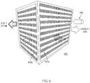
FIG. 9 is a perspective view illustrating a humidification part of according to a third embodiment of the present disclosure. -
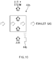
FIG. 10 is a view conceptually illustrating flows that occur in the humidification part according to the third embodiment of the present disclosure. - This application claims the benefit of priority to
Korean Patent Application No. 10-2020-0125212, filed in the Korean Intellectual Property Office on September 25, 2020 - Hereinafter, some embodiments of the present disclosure will be described in detail with reference to the exemplary drawings. In adding the reference numerals to the components of each drawing, it should be noted that the identical or equivalent component is designated by the identical numeral even when they are displayed on other drawings. Further, in describing the embodiment of the present disclosure, a detailed description of the related known configuration or function will be omitted when it is determined that it interferes with the understanding of the embodiment of the present disclosure.
- In describing the components of the embodiment according to the present disclosure, terms such as first, second, A, B, (a), (b), and the like may be used. These terms are merely intended to distinguish the components from other components, and the terms do not limit the nature, order or sequence of the components. Unless otherwise defined, all terms including technical and scientific terms used herein have the same meaning as commonly understood by one of ordinary skill in the art to which this disclosure belongs. It will be further understood that terms, such as those defined in commonly used dictionaries, should be interpreted as having a meaning that is consistent with their meaning in the context of the relevant art and will not be interpreted in an idealized or overly formal sense unless expressly so defined herein.
-
FIG. 1 is a conceptual view of awater heater 1 according to a first embodiment of the present disclosure. - Referring to the drawing, the
water heater 1 according to the first embodiment of the present disclosure includes aheating part 20 and ahumidification part 40. Thewater heater 1 may further include acase 10 for embedding other components, aduct 51 that passes through thecase 10 and is configured such that a combustion gas that passed through thehumidification part 40 is discharged to an outside, and an externalair supply pipeline 52 that passes through thecase 10 and introduces air outside thecase 10 into an interior of thecase 10. The water heater may include a boiler for providing heating, a hot water heater for providing hot water (a direct water type hot water heater that is not provided with a separate hot water tank, or a tank type hot water heater provided with a separate hot water tank), a boiler usable for a hot water heater, or the like. Hereafter, a boiler usable for a hot water heater will be described as an example. - The
heating part 20 is configured to cause a combustion reaction and generate heating water by using heat generated therefrom. The heating water includes at least one of heating water or hot water. Theheating part 20 includes aburner 26. Theheating part 20 may include a heat exchanger. - The
burner 26 is configured to cause a combustion reaction from air and a fuel. Accordingly, theburner 26 may include a burnerair supply pipeline 263 that receives air, afuel pipeline 262 that receives the fuel, and acombustion part 261 that causes the combustion reaction by using the received air and fuel. - The
heating part 20 may include a combustion chamber, in which flames generated through the combustion reaction may be located. Theheating part 20 may include ahousing 21 to define a combustion chamber in thehousing 21. Water may be injected into an interior of the combustion chamber such that a temperature of the combustion gas is within a specific range. As in the contents on thehumidification part 40, which will be described below, the water may be injected in a scheme, in which the water is sprayed into the interior of the combustion chamber, by using a nozzle or the like. The water injected into the combustion chamber may be condensate CW formed through condensation of a combustion gas. - The heat exchanger of the
heating part 20 may include a heatingwater heat exchanger 22 and a hotwater heat exchanger 30. The heatingwater heat exchanger 22 may be embedded in thehousing 21. The heatingwater heat exchanger 22 may generate heating water by heating water by using convection heat generated through the combustion reaction, and sensible heat and latent heat received from the combustion gas generated from flames located in the combustion chamber. Accordingly, the heatingwater heat exchanger 22 may be formed in a form of a pipeline, through which water may flow and in which the combustion gas may flow along an outer surface thereof. The heatingwater heat exchanger 22 may further include heat transfer fins for increasing a heat transfer area thereof. However, the form of the heatingwater heat exchanger 22 is not limited thereto, and may be of a plate type. The heatingwater heat exchanger 22 may include a sensible heat type heat exchanger that uses sensible heat, and a latent heat type heat exchanger that uses latent heat. The heating water may be heated first in the latent heat type heat exchanger, and may be heated finally by the sensible heat type heat exchanger. In the drawing, it may be considered that the latent heat type heat exchanger is located on a lower side and the sensible heat type heat exchanger is located on an upper side. - The heating water may be delivered to a
heating pipeline 70 located in a heating target that requires external heating to be used as the heating water. A closed circuit that allows the heating water to return to the heatingwater heat exchanger 22 in an interior of theheating part 20 such that the heating water is circulated after heat is transferred to the heating target may be formed. - The heating water may be delivered to the hot
water heat exchanger 30 by acirculation pipeline 23 connected to the heatingwater heat exchanger 22 to be used to generate hot water. Opposite ends of thecirculation pipeline 23 may be connected to the heatingwater heat exchanger 22 and may be configured such that the heating water is circulated. The hotwater heat exchanger 30 may be disposed outside thehousing 21, but may be disposed in an interior of thehousing 21. The hotwater heat exchanger 30 may receive direct water and generate hot water by exchanging heat with the heating water. The hot water may be discharged to a source of demand to be used. The hotwater heat exchanger 30 may be configured such that a hot water direct water pipeline 61 passes therethrough such that the direct water is introduced from the outside and is discharged after becoming hot water. Adirect water pipeline 60, through which direct water is introduced from the outside to an interior of thecase 10 may be divided into the hot water direct water pipeline 61 and a humidifyingdirect water pipeline 62. - Although it has been described in the first embodiment of the present disclosure that the heat exchanger includes the heating
water heat exchanger 22 and the hotwater heat exchanger 30, it may include only one of the heatingwater heat exchanger 22 and the hotwater heat exchanger 30, and the hotwater heat exchanger 30 of a type that directly uses heat generated through a combustion reaction in heating hot water may be used. Theheating part 20 is not limited to the one described and illustrated in the first embodiment of the present disclosure, and may be formed of a hot water storage type. - The combustion gas may be condensed to generate condensate CW. The condensate CW may be discharged through a
water discharge pipeline 25 located at a lower end of theheating part 20. A trap may be disposed in thewater discharge pipeline 25 such that the combustion gas is prevented from being discharged therethrough, and a neutralization device may be disposed to neutralize and discharge the condensate CW that is acidic. - To provide the combustion gas to the
humidification part 40, which will be described below, theheating part 20 may further include anintermediate pipeline 24 that connects thehousing 21 and thehumidification part 40. Theintermediate pipeline 24 may deliver the combustion gas that passed through the heat exchanger to exchange heat to thehumidification part 40. -
FIG. 2 is a perspective view illustrating thehumidification part 40 of thewater heater 1 according to the first embodiment of the present disclosure.FIG. 3 is a perspective view illustrating the humidification part ofFIG. 2 , from another angle.FIG. 4 is a view illustrating the humidification part of the water heater according to the first embodiment of the present disclosure, from an upper side to a lower side.FIG. 5 is a view illustrating the humidification part of the water heater according to the first embodiment of the present disclosure, from the lower side to the upper side.FIG. 6 is a view illustrating flows that occur in thehumidification part 40 of thewater heater 1 and parts connected to thehumidification part 40, according to the first embodiment of the present disclosure.FIG. 7 is a view illustrating flows inwet channels 431 anddry channels 432 of thehumidification part 40 of thewater heater 1 according to the first embodiment of the present disclosure. - The
humidification part 40 is a component that is configured to provide humidified air to theburner 26. Thehumidification part 40 is configured to generate steam by steaming water and provide the steam, together with the air, to theburner 26. To generate steam, thehumidification part 40 may use the combustion gas that is generated through the combustion reaction and is discharged from theheating part 20 after heat is transferred to the heating water. Because the combustion gas has a high temperature after the heat is transferred to the heating water, thehumidification part 40 may generate steam by using heat left in the combustion gas. Because thehumidification part 40 performs an operation of generating the steam, thehumidification part 40 may be formed of a material having a corrosion-resistant property, such as stainless steel, to be prevented from being corroded due to moisture and durability thereof from being degraded. - The
humidification part 40 may include a plurality ofwet channels 431 and a plurality ofdry channels 432. Thedry channels 432 provide a space, through which the combustion gas passes, and thewet channels 431 provide a space, through which the air delivered from the outside flows and passes, from which the water is ejected, and in which the ejected water is steamed to become steam. Thewet channels 431 and thedry channels 432 may be divided such that different materials cannot be communicated therebetween. - The plurality of
dry channels 432 and the plurality ofwet channels 431 may be alternately disposed such that heat is efficiently exchanged. Because thedry channels 432 and thewet channels 431 are disposed alternately, a heat exchange area becomes larger, whereby the heat of the combustion gas that passes through thedry channels 432 may be efficiently transferred to water drops "D" formed on inner surfaces of thewet channels 431 after being ejected from thewet channels 431. Furthermore, the fluids that flow in thewet channels 431 and thedry channels 432 may not directly meet each other but may indirectly exchange heat. - The
humidification part 40 may include a plurality ofpartition plates 433. Thepartition plates 433 having a plate shape may be disposed in parallel to each other at a specific interval, and may define the plurality ofwet channels 431 and the plurality ofdry channels 432. - The
humidification part 40 may further include a plurality of heat transfer fins. The heat transfer fins may be disposed betweenadjacent partition plates 433. The heat transfer fins may contact at least one of theadjacent partition plates 433 to increase a heat transfer area of thepartition plate 433. The heat transfer fins may be disposed on the surfaces of thepartition plates 433 to protrude from the surfaces. Among the plurality of heat transfer fins, heat transfer fins that protrude in opposite directions and face each other may contact each other. The heat transfer fins may be disposed on an inner side of thewet channels 431 and thedry channels 432 to increase heat exchange efficiencies in the channels. In the drawings, the heat transfer fins are not illustrated separately. - Among the side surfaces of the
partition plates 433, side surfaces that define inner surfaces of thewet channels 431 may be hydrophilic surfaces. A hydrophilic treatment is performed on the inner surfaces of thewet channels 431, and thus they may become hydrophilic surfaces. Chemical etching, a solgel method, a surface coating method, and a negative ion exchange method may be used as the hydrophilic treatment. Depressions and bosses may be formed on the inner surfaces of thewet channels 431 such that water drops are generated so that heat may be easily transferred. Because the inner surfaces of thewet channels 431 are hydrophilic, the ejected water may be easily located on the inner surfaces of thewet channels 431, and the heat of the combustion gas that passes through thedry channels 432 may be easily transferred for steaming. - The
humidification part 40 may further include anozzle 44. Thenozzle 44 is configured to eject water to the plurality ofwet channels 431. Thenozzle 44 may be disposed on an upper side of the plurality ofwet channels 431, and may be configured such that the ejected water is lowered by the self-weight thereof to be uniformly distributed in thewet channels 431. Thenozzle 44 may directly eject the water to thewet channels 431, but may be disposed to eject the water to an upper side while facing the upper side. Thenozzle 44 may spray the water in a form of small water drops. - The water may be provided by direct water that is delivered from at least one water source. Accordingly, the
nozzle 44 may eject the direct water to the plurality ofwet channels 431 by using a direct hydraulic pressure. Thenozzle 44 may be connected to the humidifyingdirect water pipeline 62 to receive direct water. - The
humidification part 40 may include ahumidification body 43, a firstpassage guide part 41, and a secondpassage guide part 42. The firstpassage guide part 41 may be disposed on a lower side of thehumidification body 43 and the secondpassage guide part 42 may be disposed on an upper side of thehumidification body 43, but the dispositions thereof are not limited thereto. - The
humidification body 43 may include a main dry channel and a main wet channel. The firstpassage guide part 41 may include a first passage guide dry-channel and a first passage guide wet-channel, and the secondpassage guide part 42 may include a second passage guide dry-channel and a second passage guide wet-channel. Thedry channel 432 may be formed by sequentially connecting the first passage guide dry-channel, the main dry channel, and the second passage guide dry-channel. Thewet channel 431 may be formed by sequentially connecting the second passage guide wet-channel, the main wet channel, and the first passage guide wet-channel. A combustion gas discharge passage, through which the combustion gas flows from theheating part 20 to the outside to be discharged, is formed along thedry channels 432, and an air supply passage, through which the air and the steam are introduced from the outside to theburner 26, is formed along thewet channels 431. The air supplied by the air supply passage and the combustion gas discharged by the combustion gas discharge passage cross each other in thehumidification part 40 for heat exchange. In particular, the supplied air and the combustion gas may counterflow with respect to each other in opposite directions in thehumidification body 43 as illustrated, for heat exchange. - The first passage guide dry-channel is configured to guide the combustion gas discharged from the
heating part 20 to the main dry channel. Accordingly, the first passage guide dry-channel may be connected to theintermediate pipeline 24 and thehumidification body 43. The first passage guide wet-channel is configured to guide the air and the steam discharged from the main wet channel to theburner 26. Accordingly, the first passage guide wet-channel may be connected to the burnerair supply pipeline 263 and thehumidification body 43. - The second passage guide wet-channel is configured to guide the air supplied from an outside of the
humidification part 40 to the main wet channel. Accordingly, the second passage guide wet-channel may be connected to the externalair supply pipeline 52, which is a pipeline that is opened to the outside such that the external air is introduced therethrough, and thehumidification body 43. The second passage guide dry-channel is configured to guide the steam discharged from the main dry channel to theduct 51. Accordingly, the second passage guide dry-channel may be connected to theduct 51 and thehumidification body 43. - The first passage guide may have a
first body surface 411 that is a surface connected to thehumidification body 43. The outlet of the first passage guide dry-channel and the inlet of the first passage guide wet-channel may be disposed together on, among the side surfaces of the first passage guide, thefirst body surface 411 that is a surface connected to thehumidification body 43. However, the inlet of the first passage guide dry-channel and the outlet of the first passage guide wet-channel may be disposed, respectively, on a first passageguide inlet surface 413 and a first passageguide outlet surface 412 that are, among the side surfaces of the first passage guide, two surfaces that are different from thefirst body surface 411. That is, when viewed in the same direction as that ofFIG. 6 , the first passage guide may have a triangular shape. Because the first passageguide outlet surface 412 may be formed to face a lower side, the outlets of thewet channels 431 formed on the first passageguide outlet surface 412 may be opened to face the lower side. Accordingly, the steam included in the supplied air provided through thewet channels 431 or the water injected into thewet channels 431 may flow along thewet channels 431 or drop to reach the inlet of the burnerair supply pipeline 263. The outlet of thehumidification part 40 may include the outlets of thewet channels 431 formed in the firstpassage guide part 41, and the outlets of thedry channels 432 formed in the secondpassage guide part 42. - The second passage guide may have a
second body surface 421 that is a surface connected to thehumidification body 43. The inlet of the second passage guide dry-channel and the outlet of the second passage guide wet-channel may be disposed together on, among the side surfaces of the second passage guide, thesecond body surface 421 that is a surface connected to thehumidification body 43. However, the outlet of the second passage guide dry-channel and the inlet of the second passage guide wet-channel may be disposed, respectively, on a second passageguide outlet surface 422 and a second passageguide inlet surface 423 that are, among the side surfaces of the second passage guide, two surfaces that are different from thesecond body surface 421. That is, when viewed in the same direction as that ofFIG. 6 , the second passage guide may have a triangular shape. However, the shapes of the first passage guide and the second passage guide are not limited thereto. - The first passage guide may be directly or indirectly coupled to the
intermediate pipeline 24 of theheating part 20 through brazing welding. The second passage guide may be coupled to theduct 51 through brazing welding. Accordingly, thehumidification part 40 may be easily coupled to other components. Furthermore, the components of thehumidification part 40 also may be formed as a single body through brazing welding, or all or some components may be integrally formed through a scheme, such as injectionmolding. That is, the firstpassage guide part 41, the secondpassage guide part 42, and thehumidification body 43 have been described in the specification as separate components, but at least some of them may constitute an integral component. The above-described brazing-welded part may be further sealed by further using another unit. - A siphon
part 83 may be connected to an inlet of the burnerair supply pipeline 263 that connects thehumidification part 40 and thecombustion part 261, which is connected to thehumidification part 40. The siphonpart 83 may be a pipe that has a "U"-shaped part to cause a siphon phenomenon and has a serpentine shape. The water that is generated through condensation again as the supplied air including the steam discharged to the burnerair supply pipeline 263 is condensed, or the water that is injected into thehumidification part 40 but has not been steamed yet, and flows down and drops may gather in the siphonpart 83. The gathering water may be collected in the siphonpart 83 to define a "U"shaped trap. When a specific volume or more of water gathers in the siphonpart 83, the siphon phenomenon occurs and the water that defines the trap may be discharged at the same time. - Meanwhile, in a modification of an embodiment of the present disclosure, an air/water discharge part including a pipeline connected to a separate valve and an outside, instead of the siphon
part 83, may be further formed to be connected to the burnerair supply pipeline 263. Similarly to the siphonpart 83, the water may be collected in the air/water discharge part, and the water may be discharged to the outside as the valve is opened. -
FIG. 8 is a conceptual view of awater heater 2 according to a second embodiment of the present disclosure. - The
water heater 2 according to the second embodiment of the present disclosure basically has the same configuration as that of thewater heater 1 according to the first embodiment of the present disclosure, except for some parts thereof. Accordingly, only the different parts will be further described. In thewater heater 2 according to the second embodiment of the present disclosure, condensate CW instead of direct water may be supplied to thenozzle 44. Accordingly, thewater heater 2 may include apump 82 and acondensate pipeline 81, and may have adirect water pipeline 600 that is not branched from the humidifying direct water pipeline (62 ofFIG. 1 ). Thecondensate pipeline 81 connects thewater discharge pipeline 25, in which the condensate CW gathers, and thenozzle 44, and thepump 82 is disposed in thecondensate pipeline 81 to pump the condensate CW to thehumidification part 40. Thenozzle 44 may eject the condensate CW to the plurality ofwet channels 431 by using a pressure applied to the condensate CW by thepump 82. - Although it has been described in the first embodiment and the second embodiment of the present disclosure that the direct water and the condensate CW are ejected by the
nozzle 44, the water may be provided by at least one of the direct water and the condensate CW to be ejected, and the water heater, in which both of the direct water and the condensate are ejected by the nozzle or one of them is selectively ejected, may be carried out. - The flames generated by the burner that received humidified air may be stabilized and the temperature of the flames may be made to become lower, by using a scheme, in which the water is ejected to the supplied air and exchanges heat with the combustion gas as in the humidifier of the water heater of the present disclosure. Accordingly, nitrogen oxides and soot may be reduced. Because a concentration of steam in the supplied air may be increased, convection heat transfer and a concentration of radicals may be increased, whereby pollutants may be reduced. Furthermore, because the wasted heat recovery efficiency of the combustion gas increased, more condensate is generated, and fine dust and water soluble nitrogen oxides also may be easily collected.
- A higher concentration of steam in the supplied air may be obtained by using a scheme of transferring heat of the combustion gas and heating the water for humidification, as in the scheme of using the water heater of the present disclosure, as compared with a case, in which humidification is made in a scheme of simply ejecting water to the supplied air.
- In an steaming/cooing device that has a structure that is similar to that of the humidification part of the present disclosure, the air discharged from an interior may be humidified through steaming while passing through the wet channels, and the exterior air introduced into the interior may be cooled by latent heat during steaming while passing through the dry channels. In the humidification part of the present disclosure, humidification is made through steaming while the combustion gas that is heated to a high temperature passes through the dry channels and the exterior air passes through the wet channels. It may be seen that the exterior air and the interior air, a temperature difference of which is not explicit, exchange heat in the steaming/cooling device, but a temperature difference between the combustion gas of a high temperature and the exterior air is relatively large whereby heat transfer from the combustion gas to the exterior air and the sprayed water may be more effectively made in the humidification part of the present disclosure. Furthermore, in the steaming/cooling device, an obtained advantage is mere because the interior air discharged to the outside is heated. However, according to the humidification part of the present disclosure, a material, such as PVC, which has a relatively low heat-resistant property may be used as a component, such as a duct, which is used for discharging the combustion gas, by cooling the discharged combustion gas, whereby the selection of the material may be widened, and a durability of the components used for discharging the combustion gas may be increased.
-
FIG. 9 is a perspective view illustrating ahumidification part 40b of according to a third embodiment of the present disclosure.FIG. 10 is a view conceptually illustrating flows that occur in thehumidification part 40b according to the third embodiment of the present disclosure. - Configurations of the
humidification part 40b according to the third embodiment of the present disclosure are similar to those of thehumidification part 40 according to the first embodiment but only some of them are different, and thus only different parts will be additionally described. Referring to the drawings, thehumidification part 40b according to the third embodiment of the present disclosure may have a rectangular parallelepiped shape as illustrated.Wet channels 431b anddry channels 432b may be stacked alternately along an upward/downward direction. Accordingly, the supplied air and the combustion gas that flow in thewet channels 431b and thedry channels 432b may not directly meet each other but may indirectly exchange heat. - The inlets and the outlets of the
wet channels 431b may be disposed, respectively, on the front surface and the rear surface of thehumidification part 40b, which is viewed in the drawing, and the inlets and the outlets of thedry channels 432b may be disposed, respectively, on the left side surface and the right side surface of thehumidification part 40b. Accordingly, as viewed in the drawings, the supplied air that flows through thewet channels 431b and the combustion gas that flows through thedry channels 432b may indirectly cross each other in a form of cross-flows, in an interior of thehumidification part 40b. Because thehumidification part 40b according to the third embodiment of the present disclosure is formed as illustrated, thehumidification part 40b having a simplified configuration and a reduced volume may be constituted. - A
nozzle 44b for ejecting water to thewet channels 431b may be disposed to be adjacent to the front surface of thehumidification part 40b. Thenozzle 44b may apply the steaming water to thewet channels 431b in a scheme of ejecting water strongly toward the rear side, unlike thenozzle 44 of the first embodiment, which is formed such that the inlets of thewet channels 431 face the upper side to inject the water in a scheme of dropping the water. Thenozzle 44b may be disposed on a front side of the front surface of thehumidification part 40b, may be disposed to be adjacent to an upper end of the front surface, and may be inclined in a direction that becomes closer to the front surface of thehumidification part 40b with respect to the lower side to uniformly eject the water to thewet channels 431b. - Although it has been described in the third embodiment that the
wet channels 431b and thedry channels 432b of thehumidification part 40b are disposed to face the horizontal direction, it indicates a relative direction for convenience of description, and the directions, which thewet channels 431b and thedry channels 432b face may be changed according to an angle, at which thehumidification part 40b is disposed. - Although it may have been described until now that all the elements constituting the embodiments of the present disclosure are coupled to one or coupled to be operated, the present disclosure is not essentially limited to the embodiments. That is, without departing from the purpose of the present disclosure, all the elements may be selectively coupled into one or more elements to be operated. Furthermore, because the terms, such as "comprising", "including", or "having" may mean that the corresponding element may be included unless there is a specially contradictory description, it should be construed that another element is not extruded but may be further included. In addition, unless defined otherwise, all terms used herein, including technical or scientific terms, have the same meanings as those generally understood by those skilled in the art to which the present disclosure pertains. The terms, such as the terms defined in dictionaries, which are generally used, should be construed to coincide with the context meanings of the related technologies, and are not construed as ideal or excessively formal meanings unless explicitly defined in the present disclosure.
- The above description is a simple exemplification of the technical spirits of the present disclosure, and the present disclosure may be variously corrected and modified by those skilled in the art to which the present disclosure pertains without departing from the essential features of the present disclosure. Accordingly, the embodiments disclosed in the present disclosure are not provided to limit the technical spirits of the present disclosure but provided to describe the present disclosure, and the scope of the technical spirits of the present disclosure is not limited by the embodiments. Accordingly, the technical scope of the present disclosure should be construed by the attached claims, and all the technical spirits within the equivalent ranges fall within the scope of the present disclosure.
Claims (15)
- A water heater comprising:a heating part including a burner configured to cause a combustion reaction from air and a fuel, and configured to generate heating water by using heat generated through the combustion reaction; anda humidification part configured to generate steam by steaming water by using a combustion gas generated through the combustion reaction and discharged from the heating part, and to provide the steam, together with the air, to the burner.
- The water heater of claim 1, wherein the humidification part includes:a plurality of dry channels configured to provide a space, through which the combustion gas passes; anda plurality of wet channels configured to provide a space, in which the water is ejected, the ejected water is steamed, and the steam is generated, and through which the air passes, andwherein the plurality of dry channels and the plurality of wet channels are alternately disposed such that the heat of the combustion gas is delivered to the water.
- The water heater of claim 2, wherein the humidification part further includes:a humidification body including a main dry channel and a main wet channel;a first passage guide part including a first passage guide dry-channel configured to guide the combustion gas discharged from the heating part to the main dry channel, and a first passage guide wet-channel configured to guide the air and the steam discharged from the main wet channel to the burner; anda second passage guide part including a second passage guide wet-channel configured to guide the air supplied from an outside of the humidification part to the main wet channel, and a second passage guide dry-channel configured to guide the combustion gas discharged from the main dry channel to a duct for discharging the combustion gas,wherein the dry channel is formed by sequentially connecting the first passage guide dry-channel, the main dry channel, and the second passage guide dry-channel, andwherein the wet channel is formed by sequentially connecting the second passage guide wet-channel, the main wet channel, and the first passage guide wet-channel.
- The water heater of claim 3, wherein an outlet of the first passage guide dry-channel and an inlet of the first passage guide wet-channel are disposed together on, among side surfaces of the first passage guide part, a first body surface that is a surface connected to the humidification body, and an inlet of the first passage guide dry-channel and an outlet of the first passage guide wet-channel are disposed, respectively, on, among the side surfaces of the first passage guide part, two surfaces that are different from the first body surface, and
wherein an inlet of the second passage guide dry-channel and an outlet of the second passage guide wet-channel are disposed together on, among side surfaces of the second passage guide part, a second body surface that is a surface connected to the humidification body, and an outlet of the second passage guide dry-channel and an inlet of the second passage guide wet-channel are disposed, respectively, on, among the side surfaces of the second passage guide part, two surfaces that are different from the second body surface. - The water heater of claim 2, wherein the humidification part further includes:
a plurality of partition plates disposed in parallel to each other at a specific interval to define the plurality of wet channels and the plurality of dry channels. - The water heater of claim 5, wherein the humidification part further includes:
a plurality of heat transfer fins disposed between the plurality of partition plates. - The water heater of claim 2, wherein inner surfaces of the wet channels are hydrophilic surfaces.
- The water heater of claim 2, wherein the humidification part further includes:
a nozzle configured to eject the water to the plurality of wet channels. - The water heater of claim 8, wherein the nozzle is disposed on an upper side of the plurality of wet channels, and is disposed to face an upper side such that the water is ejected to the upper side.
- The water heater of claim 8, wherein the water is provided by at least direct water delivered from a source of water, and
wherein the nozzle ejects the direct water to the plurality of wet channels by using a direct hydraulic pressure. - The water heater of claim 8, further comprising:a pump configured to pump condensate generated through condensation of the combustion gas to the humidification part,wherein the water is provided by at least the condensate, andwherein the nozzle ejects the condensate to the plurality of wet channels by using a pressure applied to the condensate by the pump.
- The water heater of claim 1, wherein the humidification part is configured to cause heat exchange while the air and the combustion gas flow in an interior thereof while cross-flowing with respect to each other in opposite directions.
- The water heater of claim 1, wherein the humidification part is configured to cause heat exchange while the air and the combustion gas flow in an interior thereof while cross-flowing with respect to each other in perpendicular directions.
- The water heater of claim 1, wherein an outlet of the humidification part, from which the air and the steam, which are to be provided to the burner, is formed to face a lower side, and
wherein the water heater further comprisess:a burner air supply pipeline connecting the outlet of the humidification part and the burner; anda siphon part connected to a lower side of the burner air supply pipeline while having a "U"-shaped part such that the water, which is collected, is discharged due to a siphon phenomenon when a volume of the collected water becomes a specific volume or more while the water that flows down from the burner air supply pipeline is collected to define a trap. - A water heater comprising:a heating part including a burner configured to cause a combustion reaction from air and a fuel, a heating water heat exchanger configured to receive sensible heat and latent heat from a combustion gas generated through the combustion reaction to generate heating water by heating water, and a hot water heat exchanger configured to generate hot water by exchanging heat between the heating water and direct water;a humidification part configured to generate steam by steaming water by using the combustion gas, and through which the air passes;a water discharge pipeline configured to discharge condensate generated through condensation of the combustion gas;an air supply pipeline connecting the humidification part and the heating part to provide the air that passed through the humidification part, together with steam generated by the humidification part, to the burner; andan intermediate pipeline connecting the humidification part and the heating part to deliver the combustion gas to the humidification part.
Applications Claiming Priority (2)
| Application Number | Priority Date | Filing Date | Title |
|---|---|---|---|
| KR1020200125212A KR102658283B1 (en) | 2020-09-25 | 2020-09-25 | Water heating apparatus with humidified air supply |
| PCT/KR2021/013078 WO2022065937A1 (en) | 2020-09-25 | 2021-09-24 | Water heater receiving humidified air |
Publications (3)
| Publication Number | Publication Date |
|---|---|
| EP4113029A1 true EP4113029A1 (en) | 2023-01-04 |
| EP4113029A4 EP4113029A4 (en) | 2024-01-24 |
| EP4113029B1 EP4113029B1 (en) | 2025-05-21 |
Family
ID=80845890
Family Applications (1)
| Application Number | Title | Priority Date | Filing Date |
|---|---|---|---|
| EP21872965.5A Active EP4113029B1 (en) | 2020-09-25 | 2021-09-24 | Water heater receiving humidified air |
Country Status (4)
| Country | Link |
|---|---|
| US (1) | US12241654B2 (en) |
| EP (1) | EP4113029B1 (en) |
| KR (1) | KR102658283B1 (en) |
| WO (1) | WO2022065937A1 (en) |
Families Citing this family (1)
| Publication number | Priority date | Publication date | Assignee | Title |
|---|---|---|---|---|
| CN121067323A (en) * | 2025-11-06 | 2025-12-05 | 佛山市顺德区美的洗涤电器制造有限公司 | Heating device and cooking equipment |
Family Cites Families (16)
| Publication number | Priority date | Publication date | Assignee | Title |
|---|---|---|---|---|
| US6176305B1 (en) * | 1998-11-09 | 2001-01-23 | Building Performance Equipment Inc. | Ventilator system and method |
| JP2005241184A (en) * | 2004-02-27 | 2005-09-08 | Jfe Steel Kk | Low NOx combustion method |
| GB0503039D0 (en) * | 2005-02-14 | 2005-03-23 | Microgen Energy Ltd | Diagnostic circuit in a condensing boiler |
| US10247483B2 (en) * | 2008-09-23 | 2019-04-02 | Oxycom Beheer B.V. | Evaporative cooling device |
| JP6038588B2 (en) * | 2012-10-17 | 2016-12-07 | 三菱日立パワーシステムズ株式会社 | Humidifier, gas turbine equipped with humidifier, and method for remodeling the same |
| KR101509556B1 (en) | 2013-02-26 | 2015-04-07 | 주식회사 경동나비엔 | Combustion apparatus having air supply and exhaust gas heat exchanger |
| KR20150084194A (en) * | 2014-01-13 | 2015-07-22 | 인하대학교 산학협력단 | Condensate circulation heat recovery device and an apparatus equipped with a boiler |
| WO2015168018A1 (en) * | 2014-04-28 | 2015-11-05 | Idalex Technologies, Inc. | Heat recovery method and apparatus |
| PT3191782T (en) * | 2014-09-08 | 2021-02-04 | Seeley F F Nominees | Compact indirect evaporative cooler |
| KR101692240B1 (en) | 2015-03-12 | 2017-01-05 | 주식회사 경동나비엔 | desiccant cooling operation |
| KR20160141016A (en) | 2015-05-27 | 2016-12-08 | 주식회사 경동나비엔 | Heat exchanger of evaporative cooler for dehumidified cooling |
| KR101975888B1 (en) | 2017-09-05 | 2019-05-08 | 인하대학교 산학협력단 | Waste Heat Recovery Boiler for Additionally Spraying Water |
| KR102567170B1 (en) * | 2018-11-26 | 2023-08-16 | 주식회사 경동나비엔 | Boiler with stable hot water supply |
| KR102571858B1 (en) * | 2018-12-14 | 2023-08-28 | 주식회사 경동나비엔 | Separation type evaporative cooler |
| KR102571859B1 (en) * | 2018-12-18 | 2023-08-28 | 주식회사 경동나비엔 | Water supplying and spraying system for evaporative cooler and its operating method |
| KR20200125212A (en) | 2019-04-26 | 2020-11-04 | 에스케이하이닉스 주식회사 | accelerating Appratus of neural network and operating method thereof |
-
2020
- 2020-09-25 KR KR1020200125212A patent/KR102658283B1/en active Active
-
2021
- 2021-09-24 EP EP21872965.5A patent/EP4113029B1/en active Active
- 2021-09-24 US US17/907,632 patent/US12241654B2/en active Active
- 2021-09-24 WO PCT/KR2021/013078 patent/WO2022065937A1/en not_active Ceased
Also Published As
| Publication number | Publication date |
|---|---|
| EP4113029A4 (en) | 2024-01-24 |
| EP4113029B1 (en) | 2025-05-21 |
| US20230139832A1 (en) | 2023-05-04 |
| KR102658283B1 (en) | 2024-04-18 |
| WO2022065937A1 (en) | 2022-03-31 |
| US12241654B2 (en) | 2025-03-04 |
| KR20220041664A (en) | 2022-04-01 |
Similar Documents
| Publication | Publication Date | Title |
|---|---|---|
| US10126014B2 (en) | Heat exchanger for condensing gas boiler | |
| CA2807168C (en) | Latent heat exchanger in condensing boiler | |
| JP5043859B2 (en) | Condenser boiler heat exchanger for heating and hot water supply | |
| US10451312B2 (en) | Condensing gas water heater, condensing heat exchanger and heat exchanger plate | |
| KR101717097B1 (en) | Heat exchanger | |
| US10935278B2 (en) | Tubular heat exchanger | |
| US10288354B2 (en) | High-efficiency plate type heat exchanger | |
| KR101383616B1 (en) | Plume abatement and evaporated water recovery apparatus for a cooling tower using combined heat exchanger-condensor and method thereof | |
| EP4113029B1 (en) | Water heater receiving humidified air | |
| KR20010023994A (en) | Absorption water heater/chiller and high temperature regenerator therefor | |
| KR20170011448A (en) | Heat exchanger | |
| CN112880194A (en) | Heat exchange device and water heater | |
| US9557075B2 (en) | Condensing heat exchanger and boiler/water heater including the same | |
| US10465902B2 (en) | Combined evaporator and mixer | |
| CN218511181U (en) | Gas water heater | |
| RU2127853C1 (en) | Installation for hot-water heating and/or hot water supply | |
| CN216536974U (en) | Cooling condenser | |
| CN110513881A (en) | Heat exchanger and gas heater with it | |
| KR101717095B1 (en) | Heat exchanger | |
| KR20150108199A (en) | A latent heat exchanger having hot water heating multi-flow channels and a condensing gas boiler comprising the same | |
| KR101717094B1 (en) | Heat exchanger | |
| KR20220094779A (en) | Water heating apparatus using humidified air | |
| KR101717092B1 (en) | Heat exchanger | |
| KR102825225B1 (en) | Humidifier and water heating apparatus including same | |
| CN113237077A (en) | Condensation heat exchanger structure |
Legal Events
| Date | Code | Title | Description |
|---|---|---|---|
| STAA | Information on the status of an ep patent application or granted ep patent |
Free format text: STATUS: THE INTERNATIONAL PUBLICATION HAS BEEN MADE |
|
| PUAI | Public reference made under article 153(3) epc to a published international application that has entered the european phase |
Free format text: ORIGINAL CODE: 0009012 |
|
| STAA | Information on the status of an ep patent application or granted ep patent |
Free format text: STATUS: REQUEST FOR EXAMINATION WAS MADE |
|
| 17P | Request for examination filed |
Effective date: 20220929 |
|
| AK | Designated contracting states |
Kind code of ref document: A1 Designated state(s): AL AT BE BG CH CY CZ DE DK EE ES FI FR GB GR HR HU IE IS IT LI LT LU LV MC MK MT NL NO PL PT RO RS SE SI SK SM TR |
|
| DAV | Request for validation of the european patent (deleted) | ||
| DAX | Request for extension of the european patent (deleted) | ||
| A4 | Supplementary search report drawn up and despatched |
Effective date: 20240102 |
|
| RIC1 | Information provided on ipc code assigned before grant |
Ipc: F22B 27/16 20060101ALI20231219BHEP Ipc: F23L 7/00 20060101ALI20231219BHEP Ipc: F28D 21/00 20060101ALI20231219BHEP Ipc: F24H 1/00 20220101ALI20231219BHEP Ipc: F24H 9/18 20220101AFI20231219BHEP |
|
| GRAP | Despatch of communication of intention to grant a patent |
Free format text: ORIGINAL CODE: EPIDOSNIGR1 |
|
| STAA | Information on the status of an ep patent application or granted ep patent |
Free format text: STATUS: GRANT OF PATENT IS INTENDED |
|
| INTG | Intention to grant announced |
Effective date: 20250129 |
|
| GRAS | Grant fee paid |
Free format text: ORIGINAL CODE: EPIDOSNIGR3 |
|
| GRAA | (expected) grant |
Free format text: ORIGINAL CODE: 0009210 |
|
| STAA | Information on the status of an ep patent application or granted ep patent |
Free format text: STATUS: THE PATENT HAS BEEN GRANTED |
|
| P01 | Opt-out of the competence of the unified patent court (upc) registered |
Free format text: CASE NUMBER: APP_15572/2025 Effective date: 20250331 |
|
| AK | Designated contracting states |
Kind code of ref document: B1 Designated state(s): AL AT BE BG CH CY CZ DE DK EE ES FI FR GB GR HR HU IE IS IT LI LT LU LV MC MK MT NL NO PL PT RO RS SE SI SK SM TR |
|
| REG | Reference to a national code |
Ref country code: GB Ref legal event code: FG4D |
|
| REG | Reference to a national code |
Ref country code: CH Ref legal event code: EP |
|
| REG | Reference to a national code |
Ref country code: DE Ref legal event code: R096 Ref document number: 602021031270 Country of ref document: DE |
|
| REG | Reference to a national code |
Ref country code: IE Ref legal event code: FG4D |
|
| REG | Reference to a national code |
Ref country code: NL Ref legal event code: FP |
|
| PGFP | Annual fee paid to national office [announced via postgrant information from national office to epo] |
Ref country code: NL Payment date: 20250704 Year of fee payment: 5 |
|
| PG25 | Lapsed in a contracting state [announced via postgrant information from national office to epo] |
Ref country code: FI Free format text: LAPSE BECAUSE OF FAILURE TO SUBMIT A TRANSLATION OF THE DESCRIPTION OR TO PAY THE FEE WITHIN THE PRESCRIBED TIME-LIMIT Effective date: 20250521 Ref country code: PT Free format text: LAPSE BECAUSE OF FAILURE TO SUBMIT A TRANSLATION OF THE DESCRIPTION OR TO PAY THE FEE WITHIN THE PRESCRIBED TIME-LIMIT Effective date: 20250922 Ref country code: ES Free format text: LAPSE BECAUSE OF FAILURE TO SUBMIT A TRANSLATION OF THE DESCRIPTION OR TO PAY THE FEE WITHIN THE PRESCRIBED TIME-LIMIT Effective date: 20250521 |
|
| PGFP | Annual fee paid to national office [announced via postgrant information from national office to epo] |
Ref country code: DE Payment date: 20250702 Year of fee payment: 5 |
|
| REG | Reference to a national code |
Ref country code: LT Ref legal event code: MG9D |
|
| PG25 | Lapsed in a contracting state [announced via postgrant information from national office to epo] |
Ref country code: GR Free format text: LAPSE BECAUSE OF FAILURE TO SUBMIT A TRANSLATION OF THE DESCRIPTION OR TO PAY THE FEE WITHIN THE PRESCRIBED TIME-LIMIT Effective date: 20250822 Ref country code: NO Free format text: LAPSE BECAUSE OF FAILURE TO SUBMIT A TRANSLATION OF THE DESCRIPTION OR TO PAY THE FEE WITHIN THE PRESCRIBED TIME-LIMIT Effective date: 20250821 |
|
| PG25 | Lapsed in a contracting state [announced via postgrant information from national office to epo] |
Ref country code: PL Free format text: LAPSE BECAUSE OF FAILURE TO SUBMIT A TRANSLATION OF THE DESCRIPTION OR TO PAY THE FEE WITHIN THE PRESCRIBED TIME-LIMIT Effective date: 20250521 |
|
| PGFP | Annual fee paid to national office [announced via postgrant information from national office to epo] |
Ref country code: IT Payment date: 20250827 Year of fee payment: 5 |
|
| PG25 | Lapsed in a contracting state [announced via postgrant information from national office to epo] |
Ref country code: BG Free format text: LAPSE BECAUSE OF FAILURE TO SUBMIT A TRANSLATION OF THE DESCRIPTION OR TO PAY THE FEE WITHIN THE PRESCRIBED TIME-LIMIT Effective date: 20250521 |
|
| PGFP | Annual fee paid to national office [announced via postgrant information from national office to epo] |
Ref country code: GB Payment date: 20250703 Year of fee payment: 5 |
|
| PG25 | Lapsed in a contracting state [announced via postgrant information from national office to epo] |
Ref country code: HR Free format text: LAPSE BECAUSE OF FAILURE TO SUBMIT A TRANSLATION OF THE DESCRIPTION OR TO PAY THE FEE WITHIN THE PRESCRIBED TIME-LIMIT Effective date: 20250521 |
|
| PG25 | Lapsed in a contracting state [announced via postgrant information from national office to epo] |
Ref country code: RS Free format text: LAPSE BECAUSE OF FAILURE TO SUBMIT A TRANSLATION OF THE DESCRIPTION OR TO PAY THE FEE WITHIN THE PRESCRIBED TIME-LIMIT Effective date: 20250821 |
|
| PG25 | Lapsed in a contracting state [announced via postgrant information from national office to epo] |
Ref country code: IS Free format text: LAPSE BECAUSE OF FAILURE TO SUBMIT A TRANSLATION OF THE DESCRIPTION OR TO PAY THE FEE WITHIN THE PRESCRIBED TIME-LIMIT Effective date: 20250921 |
|
| PG25 | Lapsed in a contracting state [announced via postgrant information from national office to epo] |
Ref country code: LV Free format text: LAPSE BECAUSE OF FAILURE TO SUBMIT A TRANSLATION OF THE DESCRIPTION OR TO PAY THE FEE WITHIN THE PRESCRIBED TIME-LIMIT Effective date: 20250521 |
|
| REG | Reference to a national code |
Ref country code: AT Ref legal event code: MK05 Ref document number: 1797039 Country of ref document: AT Kind code of ref document: T Effective date: 20250521 |
|
| PG25 | Lapsed in a contracting state [announced via postgrant information from national office to epo] |
Ref country code: DK Free format text: LAPSE BECAUSE OF FAILURE TO SUBMIT A TRANSLATION OF THE DESCRIPTION OR TO PAY THE FEE WITHIN THE PRESCRIBED TIME-LIMIT Effective date: 20250521 Ref country code: AT Free format text: LAPSE BECAUSE OF FAILURE TO SUBMIT A TRANSLATION OF THE DESCRIPTION OR TO PAY THE FEE WITHIN THE PRESCRIBED TIME-LIMIT Effective date: 20250521 Ref country code: SM Free format text: LAPSE BECAUSE OF FAILURE TO SUBMIT A TRANSLATION OF THE DESCRIPTION OR TO PAY THE FEE WITHIN THE PRESCRIBED TIME-LIMIT Effective date: 20250521 |
|
| PG25 | Lapsed in a contracting state [announced via postgrant information from national office to epo] |
Ref country code: CZ Free format text: LAPSE BECAUSE OF FAILURE TO SUBMIT A TRANSLATION OF THE DESCRIPTION OR TO PAY THE FEE WITHIN THE PRESCRIBED TIME-LIMIT Effective date: 20250521 |
|
| PG25 | Lapsed in a contracting state [announced via postgrant information from national office to epo] |
Ref country code: EE Free format text: LAPSE BECAUSE OF FAILURE TO SUBMIT A TRANSLATION OF THE DESCRIPTION OR TO PAY THE FEE WITHIN THE PRESCRIBED TIME-LIMIT Effective date: 20250521 |
|
| PG25 | Lapsed in a contracting state [announced via postgrant information from national office to epo] |
Ref country code: SK Free format text: LAPSE BECAUSE OF FAILURE TO SUBMIT A TRANSLATION OF THE DESCRIPTION OR TO PAY THE FEE WITHIN THE PRESCRIBED TIME-LIMIT Effective date: 20250521 |
|
| PG25 | Lapsed in a contracting state [announced via postgrant information from national office to epo] |
Ref country code: RO Free format text: LAPSE BECAUSE OF FAILURE TO SUBMIT A TRANSLATION OF THE DESCRIPTION OR TO PAY THE FEE WITHIN THE PRESCRIBED TIME-LIMIT Effective date: 20250521 |
|
| REG | Reference to a national code |
Ref country code: DE Ref legal event code: R097 Ref document number: 602021031270 Country of ref document: DE |
|
| PLBE | No opposition filed within time limit |
Free format text: ORIGINAL CODE: 0009261 |
|
| STAA | Information on the status of an ep patent application or granted ep patent |
Free format text: STATUS: NO OPPOSITION FILED WITHIN TIME LIMIT |
|
| REG | Reference to a national code |
Ref country code: CH Ref legal event code: L10 Free format text: ST27 STATUS EVENT CODE: U-0-0-L10-L00 (AS PROVIDED BY THE NATIONAL OFFICE) Effective date: 20260402 |
|
| 26N | No opposition filed |
Effective date: 20260224 |
|
| REG | Reference to a national code |
Ref country code: CH Ref legal event code: H13 Free format text: ST27 STATUS EVENT CODE: U-0-0-H10-H13 (AS PROVIDED BY THE NATIONAL OFFICE) Effective date: 20260504 |