EP4112956A1 - Cylindrical roller bearing with outer ring - Google Patents
Cylindrical roller bearing with outer ring Download PDFInfo
- Publication number
- EP4112956A1 EP4112956A1 EP21760364.6A EP21760364A EP4112956A1 EP 4112956 A1 EP4112956 A1 EP 4112956A1 EP 21760364 A EP21760364 A EP 21760364A EP 4112956 A1 EP4112956 A1 EP 4112956A1
- Authority
- EP
- European Patent Office
- Prior art keywords
- axial direction
- outer ring
- retainer
- portions
- protrusion
- Prior art date
- Legal status (The legal status is an assumption and is not a legal conclusion. Google has not performed a legal analysis and makes no representation as to the accuracy of the status listed.)
- Granted
Links
Images






Classifications
-
- F—MECHANICAL ENGINEERING; LIGHTING; HEATING; WEAPONS; BLASTING
- F16—ENGINEERING ELEMENTS AND UNITS; GENERAL MEASURES FOR PRODUCING AND MAINTAINING EFFECTIVE FUNCTIONING OF MACHINES OR INSTALLATIONS; THERMAL INSULATION IN GENERAL
- F16C—SHAFTS; FLEXIBLE SHAFTS; ELEMENTS OR CRANKSHAFT MECHANISMS; ROTARY BODIES OTHER THAN GEARING ELEMENTS; BEARINGS
- F16C19/00—Bearings with rolling contact, for exclusively rotary movement
- F16C19/22—Bearings with rolling contact, for exclusively rotary movement with bearing rollers essentially of the same size in one or more circular rows, e.g. needle bearings
- F16C19/24—Bearings with rolling contact, for exclusively rotary movement with bearing rollers essentially of the same size in one or more circular rows, e.g. needle bearings for radial load mainly
- F16C19/26—Bearings with rolling contact, for exclusively rotary movement with bearing rollers essentially of the same size in one or more circular rows, e.g. needle bearings for radial load mainly with a single row of rollers
-
- F—MECHANICAL ENGINEERING; LIGHTING; HEATING; WEAPONS; BLASTING
- F16—ENGINEERING ELEMENTS AND UNITS; GENERAL MEASURES FOR PRODUCING AND MAINTAINING EFFECTIVE FUNCTIONING OF MACHINES OR INSTALLATIONS; THERMAL INSULATION IN GENERAL
- F16C—SHAFTS; FLEXIBLE SHAFTS; ELEMENTS OR CRANKSHAFT MECHANISMS; ROTARY BODIES OTHER THAN GEARING ELEMENTS; BEARINGS
- F16C19/00—Bearings with rolling contact, for exclusively rotary movement
- F16C19/22—Bearings with rolling contact, for exclusively rotary movement with bearing rollers essentially of the same size in one or more circular rows, e.g. needle bearings
- F16C19/44—Needle bearings
- F16C19/46—Needle bearings with one row or needles
- F16C19/466—Needle bearings with one row or needles comprising needle rollers and an outer ring, i.e. subunit without inner ring
-
- F—MECHANICAL ENGINEERING; LIGHTING; HEATING; WEAPONS; BLASTING
- F16—ENGINEERING ELEMENTS AND UNITS; GENERAL MEASURES FOR PRODUCING AND MAINTAINING EFFECTIVE FUNCTIONING OF MACHINES OR INSTALLATIONS; THERMAL INSULATION IN GENERAL
- F16C—SHAFTS; FLEXIBLE SHAFTS; ELEMENTS OR CRANKSHAFT MECHANISMS; ROTARY BODIES OTHER THAN GEARING ELEMENTS; BEARINGS
- F16C33/00—Parts of bearings; Special methods for making bearings or parts thereof
- F16C33/30—Parts of ball or roller bearings
- F16C33/46—Cages for rollers or needles
- F16C33/4605—Details of interaction of cage and race, e.g. retention or centring
-
- F—MECHANICAL ENGINEERING; LIGHTING; HEATING; WEAPONS; BLASTING
- F16—ENGINEERING ELEMENTS AND UNITS; GENERAL MEASURES FOR PRODUCING AND MAINTAINING EFFECTIVE FUNCTIONING OF MACHINES OR INSTALLATIONS; THERMAL INSULATION IN GENERAL
- F16C—SHAFTS; FLEXIBLE SHAFTS; ELEMENTS OR CRANKSHAFT MECHANISMS; ROTARY BODIES OTHER THAN GEARING ELEMENTS; BEARINGS
- F16C33/00—Parts of bearings; Special methods for making bearings or parts thereof
- F16C33/30—Parts of ball or roller bearings
- F16C33/46—Cages for rollers or needles
- F16C33/4617—Massive or moulded cages having cage pockets surrounding the rollers, e.g. machined window cages
- F16C33/4623—Massive or moulded cages having cage pockets surrounding the rollers, e.g. machined window cages formed as one-piece cages, i.e. monoblock cages
- F16C33/4635—Massive or moulded cages having cage pockets surrounding the rollers, e.g. machined window cages formed as one-piece cages, i.e. monoblock cages made from plastic, e.g. injection moulded window cages
-
- F—MECHANICAL ENGINEERING; LIGHTING; HEATING; WEAPONS; BLASTING
- F16—ENGINEERING ELEMENTS AND UNITS; GENERAL MEASURES FOR PRODUCING AND MAINTAINING EFFECTIVE FUNCTIONING OF MACHINES OR INSTALLATIONS; THERMAL INSULATION IN GENERAL
- F16C—SHAFTS; FLEXIBLE SHAFTS; ELEMENTS OR CRANKSHAFT MECHANISMS; ROTARY BODIES OTHER THAN GEARING ELEMENTS; BEARINGS
- F16C33/00—Parts of bearings; Special methods for making bearings or parts thereof
- F16C33/30—Parts of ball or roller bearings
- F16C33/46—Cages for rollers or needles
- F16C33/467—Details of individual pockets, e.g. shape or roller retaining means
- F16C33/4676—Details of individual pockets, e.g. shape or roller retaining means of the stays separating adjacent cage pockets, e.g. guide means for the bearing-surface of the rollers
-
- F—MECHANICAL ENGINEERING; LIGHTING; HEATING; WEAPONS; BLASTING
- F16—ENGINEERING ELEMENTS AND UNITS; GENERAL MEASURES FOR PRODUCING AND MAINTAINING EFFECTIVE FUNCTIONING OF MACHINES OR INSTALLATIONS; THERMAL INSULATION IN GENERAL
- F16C—SHAFTS; FLEXIBLE SHAFTS; ELEMENTS OR CRANKSHAFT MECHANISMS; ROTARY BODIES OTHER THAN GEARING ELEMENTS; BEARINGS
- F16C33/00—Parts of bearings; Special methods for making bearings or parts thereof
- F16C33/30—Parts of ball or roller bearings
- F16C33/46—Cages for rollers or needles
- F16C33/54—Cages for rollers or needles made from wire, strips, or sheet metal
- F16C33/542—Cages for rollers or needles made from wire, strips, or sheet metal made from sheet metal
- F16C33/543—Cages for rollers or needles made from wire, strips, or sheet metal made from sheet metal from a single part
-
- F—MECHANICAL ENGINEERING; LIGHTING; HEATING; WEAPONS; BLASTING
- F16—ENGINEERING ELEMENTS AND UNITS; GENERAL MEASURES FOR PRODUCING AND MAINTAINING EFFECTIVE FUNCTIONING OF MACHINES OR INSTALLATIONS; THERMAL INSULATION IN GENERAL
- F16C—SHAFTS; FLEXIBLE SHAFTS; ELEMENTS OR CRANKSHAFT MECHANISMS; ROTARY BODIES OTHER THAN GEARING ELEMENTS; BEARINGS
- F16C33/00—Parts of bearings; Special methods for making bearings or parts thereof
- F16C33/30—Parts of ball or roller bearings
- F16C33/58—Raceways; Race rings
- F16C33/581—Raceways; Race rings integral with other parts, e.g. with housings or machine elements such as shafts or gear wheels
-
- F—MECHANICAL ENGINEERING; LIGHTING; HEATING; WEAPONS; BLASTING
- F16—ENGINEERING ELEMENTS AND UNITS; GENERAL MEASURES FOR PRODUCING AND MAINTAINING EFFECTIVE FUNCTIONING OF MACHINES OR INSTALLATIONS; THERMAL INSULATION IN GENERAL
- F16C—SHAFTS; FLEXIBLE SHAFTS; ELEMENTS OR CRANKSHAFT MECHANISMS; ROTARY BODIES OTHER THAN GEARING ELEMENTS; BEARINGS
- F16C33/00—Parts of bearings; Special methods for making bearings or parts thereof
- F16C33/30—Parts of ball or roller bearings
- F16C33/58—Raceways; Race rings
- F16C33/583—Details of specific parts of races
- F16C33/585—Details of specific parts of races of raceways, e.g. ribs to guide the rollers
-
- F—MECHANICAL ENGINEERING; LIGHTING; HEATING; WEAPONS; BLASTING
- F16—ENGINEERING ELEMENTS AND UNITS; GENERAL MEASURES FOR PRODUCING AND MAINTAINING EFFECTIVE FUNCTIONING OF MACHINES OR INSTALLATIONS; THERMAL INSULATION IN GENERAL
- F16C—SHAFTS; FLEXIBLE SHAFTS; ELEMENTS OR CRANKSHAFT MECHANISMS; ROTARY BODIES OTHER THAN GEARING ELEMENTS; BEARINGS
- F16C33/00—Parts of bearings; Special methods for making bearings or parts thereof
- F16C33/30—Parts of ball or roller bearings
- F16C33/58—Raceways; Race rings
- F16C33/588—Races of sheet metal
-
- F—MECHANICAL ENGINEERING; LIGHTING; HEATING; WEAPONS; BLASTING
- F16—ENGINEERING ELEMENTS AND UNITS; GENERAL MEASURES FOR PRODUCING AND MAINTAINING EFFECTIVE FUNCTIONING OF MACHINES OR INSTALLATIONS; THERMAL INSULATION IN GENERAL
- F16C—SHAFTS; FLEXIBLE SHAFTS; ELEMENTS OR CRANKSHAFT MECHANISMS; ROTARY BODIES OTHER THAN GEARING ELEMENTS; BEARINGS
- F16C43/00—Assembling bearings
- F16C43/04—Assembling rolling-contact bearings
- F16C43/06—Placing rolling bodies in cages or bearings
- F16C43/065—Placing rolling bodies in cages or bearings in cages
-
- F—MECHANICAL ENGINEERING; LIGHTING; HEATING; WEAPONS; BLASTING
- F16—ENGINEERING ELEMENTS AND UNITS; GENERAL MEASURES FOR PRODUCING AND MAINTAINING EFFECTIVE FUNCTIONING OF MACHINES OR INSTALLATIONS; THERMAL INSULATION IN GENERAL
- F16C—SHAFTS; FLEXIBLE SHAFTS; ELEMENTS OR CRANKSHAFT MECHANISMS; ROTARY BODIES OTHER THAN GEARING ELEMENTS; BEARINGS
- F16C2220/00—Shaping
- F16C2220/02—Shaping by casting
- F16C2220/04—Shaping by casting by injection-moulding
-
- F—MECHANICAL ENGINEERING; LIGHTING; HEATING; WEAPONS; BLASTING
- F16—ENGINEERING ELEMENTS AND UNITS; GENERAL MEASURES FOR PRODUCING AND MAINTAINING EFFECTIVE FUNCTIONING OF MACHINES OR INSTALLATIONS; THERMAL INSULATION IN GENERAL
- F16C—SHAFTS; FLEXIBLE SHAFTS; ELEMENTS OR CRANKSHAFT MECHANISMS; ROTARY BODIES OTHER THAN GEARING ELEMENTS; BEARINGS
- F16C2220/00—Shaping
- F16C2220/40—Shaping by deformation without removing material
- F16C2220/42—Shaping by deformation without removing material by working of thin-walled material such as sheet or tube
-
- F—MECHANICAL ENGINEERING; LIGHTING; HEATING; WEAPONS; BLASTING
- F16—ENGINEERING ELEMENTS AND UNITS; GENERAL MEASURES FOR PRODUCING AND MAINTAINING EFFECTIVE FUNCTIONING OF MACHINES OR INSTALLATIONS; THERMAL INSULATION IN GENERAL
- F16C—SHAFTS; FLEXIBLE SHAFTS; ELEMENTS OR CRANKSHAFT MECHANISMS; ROTARY BODIES OTHER THAN GEARING ELEMENTS; BEARINGS
- F16C2220/00—Shaping
- F16C2220/80—Shaping by separating parts, e.g. by severing, cracking
- F16C2220/84—Shaping by separating parts, e.g. by severing, cracking by perforating; by punching; by stamping-out
-
- F—MECHANICAL ENGINEERING; LIGHTING; HEATING; WEAPONS; BLASTING
- F16—ENGINEERING ELEMENTS AND UNITS; GENERAL MEASURES FOR PRODUCING AND MAINTAINING EFFECTIVE FUNCTIONING OF MACHINES OR INSTALLATIONS; THERMAL INSULATION IN GENERAL
- F16C—SHAFTS; FLEXIBLE SHAFTS; ELEMENTS OR CRANKSHAFT MECHANISMS; ROTARY BODIES OTHER THAN GEARING ELEMENTS; BEARINGS
- F16C2361/00—Apparatus or articles in engineering in general
- F16C2361/61—Toothed gear systems, e.g. support of pinion shafts
Definitions
- the present invention relates to a cylindrical roller bearing with an outer ring, and particularly relates to a cylindrical roller bearing with an outer ring to be applied to a transmission or the like.
- a holding tab provided on a ring portion of a retainer is engaged with an inclined surface portion formed on an inner ring or an outer ring to prevent the retainer from falling off.
- a protrusion is provided on an axial side surface of a retainer, and the protrusion is engaged with a hole provided in an annular guide member disposed on a lateral side of the retainer, and thereby an inward flange of an outer ring is sandwiched between cylindrical rollers and the guide member, and the retainer is prevented from falling off from the outer ring.
- Patent Literature 1 since it is necessary to machine the inclined surface portion or the like on the inner ring, there is a problem that the manufacturing cost is increased. Further, in Patent Literature 2, since the guide member is separately provided in order to prevent the retainer from falling off, there are problems that the number of components is increased, the manufacturing cost is increased, and the assembling workability is also reduced.
- Patent Literature 2 in a case of a cylindrical roller bearing in which the cylindrical rollers directly roll on an outer circumferential surface of a shaft, it is required that the cylindrical rollers can be easily inserted into the retainer and that the cylindrical rollers are prevented from falling off from the retainer during transportation before assembly to the shaft.
- the present invention has been made in view of the above-described problems, and an object of the present invention is to provide a cylindrical roller bearing with an outer ring which can prevent a retainer from falling off from the outer ring with good assembly workability without increasing the number of components, and which takes into consideration insertion workability of cylindrical rollers and prevention of the cylindrical rollers from falling off from the retainer.
- the annular portion of the retainer on the other side in the axial direction is provided with the plurality of protrusion portions each having the engaging portion protruding farther radially outward with respect to the inner circumferential surface of the inward flange portion, the inward flange portion of the outer ring is sandwiched between the cylindrical rollers and the protrusion portions, and the retainer can be prevented from falling off from the outer ring without increasing the number of components with good assembly workability.
- the distance between the flat surface portions of the adjacent column portions is 101.5% to 107% of the roller diameter
- the circumferential protrusion amount of the outer diameter-side retaining portion from the flat surface portion is 1% to 4% of the roller diameter
- the circumferential protrusion amount of the inner diameter-side retaining portion from the flat surface portion is 4% to 10% of the roller diameter
- a cylindrical roller bearing 10 with an outer ring includes an outer ring 11, a plurality of cylindrical rollers 20, and a retainer 30.
- the outer ring 11 is formed into an annular shape by pressing a metal plate such as a thin steel plate.
- the outer ring 11 includes a cylindrical portion 13 having an outer ring raceway surface 12 on an inner circumferential surface thereof, an outward flange portion 14 extending radially outward from an end portion on one side in an axial direction of the cylindrical portion 13, and an inward flange portion 15 extending radially inward from an end portion on the other side in the axial direction of the cylindrical portion 13.
- the retainer 30 is made of resin, and as illustrated in FIGS. 4A and 4B , includes a pair of annular portions 31, 32 spaced apart in the axial direction, and a plurality of column portions 33 connecting the pair of annular portions 31, 32 and arranged at intervals in a circumferential direction.
- the plurality of cylindrical rollers 20 are held in a plurality of pockets 34 each of which is formed by adjacent column portions 33 and the pair of annular portions 31, 32 of the retainer 30, and are disposed to be rollable with respect to the outer ring raceway surface 12.
- a flat surface portion 35 in which the side surfaces of the adjacent column portions 33 forming the pocket 34 are parallel to each other, and an outer diameter-side retaining portion 36 and an inner diameter-side retaining portion 37 respectively protruding from the flat surface portion 35 in the circumferential direction on an outer diameter side and an inner diameter side are formed.
- the flat surface portions 35 guide the cylindrical rollers 20 in the circumferential direction, and the outer diameter-side retaining portions 36 and the inner diameter-side retaining portions 37 prevent the cylindrical rollers 20 from falling out of the pockets 34.
- a distance L between the flat surface portions 35 of adjacent column portions 33 is 101.5% to 107% (1.015D ⁇ L ⁇ 1.070D) of a roller diameter D
- a circumferential protrusion amount S1 of the outer diameter-side retaining portion 36 from the flat surface portion 35 is 1% to 4% (0.01D ⁇ S1 ⁇ 0.04D) of the roller diameter D
- a circumferential protrusion amount S2 of the inner diameter-side retaining portion 37 from the flat surface portion 35 is set to 4% to 10% (0.04 ⁇ S2 ⁇ 0.10D) of the roller diameter D.
- the protrusion amount S1 of the outer diameter-side retaining portion 36 is smaller than the protrusion amount S2 of the inner diameter-side retaining portion 37 (S1 ⁇ S2).
- the cylindrical roller 20 can be easily assembled into the retainer 30 without damaging the retainer 30 even when the cylindrical roller 20 is pushed into the pocket 34 of the retainer 30 from the outer diameter side. Further, since the outer ring 11 is disposed on the outer diameter side of the cylindrical rollers 20 held by the retainer 30, the cylindrical rollers 20 do not fall off from the outer diameter side of the pockets 34 when the bearing is used.
- the engagement margin on the outer diameter side can be set to be smaller than an engagement margin on the inner diameter side as long as, in an assembly process of the bearing, the retainer 30 into which the cylindrical rollers 20 are assembled can hold the cylindrical rollers 20 until the retainer 30 is inserted into the outer ring 11.
- the cylindrical rollers 20 can be prevented from falling off from the inner diameter side of the pocket 34 during transportation before assembly to the shaft or during an assembly process to the shaft.
- the flat surface portion 35 is provided in a radially intermediate portion of the pocket 34 including a position through which a pitch circle diameter PCD of each cylindrical roller 20 passes.
- the outer diameter-side retaining portion 36 and the inner diameter-side retaining portion 37 are connected to the flat surface portion 35 by inclined surfaces 38, 39, respectively.
- an angle ⁇ 1 formed by the outer diameter-side inclined surface 38 and the flat surface portion 35 is set to be smaller than an angle ⁇ 2 formed by the inner diameter-side inclined surface 39 and the flat surface portion 35 ( ⁇ 1 ⁇ ⁇ 2), and is preferably set to be about 1/3 to 1/2 of the angle ⁇ 2 ( ⁇ 2/3 ⁇ ⁇ 1 ⁇ ⁇ 2/2).
- the annular portion 32 on the other side in the axial direction is provided with, at equal intervals in the circumferential direction, a plurality of (three in the present embodiment) protrusion portions 40 each having an engaging portion 41 protruding radially outward with respect to an inner circumferential surface of the inward flange portion 15.
- the protrusion portion 40 is provided to extend toward the other side in the axial direction from an end surface on the other side in the axial direction of the annular portion 32.
- a portion having a triangular cross section which increase in thickness from the other side in the axial direction toward the one side in the axial direction has a predetermined circumferential length on an outer diameter side of the protrusion portion 40.
- An outer circumferential surface of the annular portion 32 faces the inner circumferential surface of the inward flange portion 15 with a slight radial gap therebetween, and the end surface on the other side in the axial direction of the annular portion 32 is located on (protrudes toward) the other side in the axial direction with respect to a side surface on the other side in the axial direction of the inward flange portion 15.
- the engaging portions 41 are pressed by the inner circumferential surface of the inward flange portion 15 and elastically deformed toward the inner diameter side, and thus the inward flange portion 15 climbs over the engaging portions 41. Then, the inward flange portion 15 is sandwiched at the outer circumferential surface of the annular portion 32 between axial end surfaces of the cylindrical rollers 20 and side surfaces on the one side in the axial direction of the protrusion portions 40, and the retainer 30 does not fall off from the outer ring 11 even in the single bearing.
- the cylindrical rollers are inserted from the inner side after the retainer is inserted into the outer ring, but in the present embodiment, the retainer 30 and the cylindrical rollers 20 can be combined in advance to form an intermediate assembly and then assembled to the outer ring 11, and the assemblability can be improved.
- the outward flange portion 14 of the outer ring 11 is provided with a projection portion 16, which further extends toward the outer diameter side, in a part thereof in the circumferential direction.
- the cylindrical roller bearing 10 with an outer ring is used by press-fitting the outer circumferential surface of the cylindrical portion 13 of the outer ring 11 into a mating member 50, and the projection portion 16 is fitted into a recess portion 51 of the mating member 50, and thus a position of the cylindrical roller bearing 10 with an outer ring in the circumferential direction with respect to the mating member 50 can be regulated, and creep can be prevented.
- the projection portion 16 is provided at one position in the circumferential direction, but may be provided at two or more positions.
- the annular portion 32 on the other side in the axial direction of the retainer 30 is provided with the plurality of protrusion portions 40 each having the engaging portion 41 protruding radially outward with respect to the inner circumferential surface of the inward flange portion 15, the inward flange portion 15 of the outer ring 11 is sandwiched between the cylindrical rollers 20 and the protrusion portions 40, and the retainer 30 can be prevented from falling off from the outer ring 11 without increasing the number of components with good assembly workability.
- the axial distance between the flat surface on the one side in the axial direction of the outward flange portion 14 and the end surface on the one side in the axial direction of the annular portion 32 on the one side in the axial direction is set as A
- the axial distance between the flat surface on the other side in the axial direction of the inward flange portion 15 and the side surface on the one side in the axial direction of the engaging portion 41 is set as B
- B is greater than A
- the distance L between the flat surface portions 35 of the adjacent column portions 33 is 101.5% to 107% of the roller diameter D
- the circumferential protrusion amount S1 of the outer diameter-side retaining portion 36 from the flat surface portion 35 is 1% to 4% of the roller diameter D
- the circumferential protrusion amount S2 of the inner diameter-side retaining portion 37 from the flat surface portion 35 is 4% to 10% of the roller diameter D, so that the insertion workability of the cylindrical rollers 20 and the prevention of the cylindrical rollers 20 from falling off from the retainer 30 can be realized.
- protrusion portions 40 are provided at equal intervals in the circumferential direction, and thus, as illustrated in FIG. 7 , even when the outer ring 11 is an elliptical shape (in FIG. 7 , a vertical axis passing through the projection portion 16 is a short axis, and a horizontal axis is a long axis), the retainer 30 can be prevented from coming out of the outer ring 11.
- the protrusion portions 40 may be provided at two positions facing each other in the radial direction.
- the outer ring 11 is an elliptical shape
- the outer ring 11 can be easily assembled into the retainer 30 from the axial direction by matching a phase of the long axis of the outer ring 11 having an elliptical shape with a phase in which the protrusion portion 40 of the retainer 30 is provided.
- the retainer 30 can be easily assembled into the outer ring 11.
- the total circumferential length of the protrusion portions 40 is less than 5% of the entire circumferential length, the holding force is reduced, and when the total circumferential length exceeds 20% of the entire circumferential length, the protrusion portions 40 increase in rigidity, which makes the assembly difficult.
- FIG. 9A illustrates a second modification in which the total circumferential length of the protrusion portions 40 is 20% of the entire circumferential length of the axial end surface of the retainer 30.
- FIG. 9B illustrates a third modification in which the total circumferential length of the protrusion portions 40 is 5% of the entire circumferential length of the axial end surface of the retainer 30.
- the circumferential length described above is a length along the circumferential direction at a radial position of the outer circumferential surface of the annular portion 32.
- the shape of the engaging portion 41 may be a convex curved shape in cross section, that is, a substantially hemispherical shape as in a fourth modification illustrated in FIG. 10 .
- a substantially hemispherical shape since the retainer 30 can be formed by axial drawing instead of radial drawing, cost reduction can be achieved.
- the shapes of the engaging portions 41 formed on the plurality of protrusion portions 40 on the circumference may not be the same. Further, the circumferential lengths of the protrusion portions 40 may not be the same.
- the protrusion portion 40 provided on a side surface of the annular portion 32 is located in a region in which the column portion 33 having high rigidity is disposed (in the same phase as the column portion 33) in the circumferential direction.
- the protrusion portion 40 is formed at a phase (position) which is a center in the circumferential direction of the column portion 33, and a circumferential length of the protrusion portion 40 is smaller than a circumferential length of the column portion 33.
- the circumferential length of the protrusion portion 40 may be equal to or greater than the circumferential length of the column portion 33 in a state where a circumferential center position of the column portion and a circumferential center position of the protrusion portion 40 coincide with each other.
- a circumferential position relationship (phase) between the protrusion portions 40 and the column portions 33 is any relationship depending on the number of rollers.
- the protrusion portions 40 are not necessarily disposed at equal intervals in the circumferential direction, but are preferably disposed at positions as close to each other as possible.
- the protrusion portion 40 provided on a side surface of the annular portion 32 is located in a region in which the pocket 34 are disposed (in the same phase as the pocket 34) in the circumferential direction, and slits 42 extending in the axial direction from the annular portion 32 are formed in the column portions 33 on both sides in the circumferential direction of the pocket 34 at which the protrusion portion 40 is located.
- the slit 42 is formed in a circumferential center portion of the column portion 33 up to an axial middle position.
- the protrusion portions 40 of the retainer 30b are easily deformed, and the assemblability between the outer ring 11 and the retainer 30b can be improved.
- a retainer 30c includes the pair of annular portions 31, 32, the column portions 33, and the protrusion portions 40 as in the above-described embodiment, but the retainer 30c is made of iron.
- the protrusion portions 40 are provided at three positions at equal intervals in the circumferential direction.
- an outer diameter of the annular portion 32 corresponds to an inner diameter of the inward flange portion 15 and is smaller than an outer diameter of the annular portion 31.
- the outer diameter of the annular portion 32 may be set to be the same as the outer diameter of the annular portion 31 by reducing a radial dimension of the inward flange portion 15.
- the outer diameters of the pair of annular portions 31, 32 may have the same dimension by reducing the outer diameter of the annular portion 31.
- the protrusion portion may be formed by providing, on both sides in the circumferential direction of the protrusion portion, a slit extending toward the one side in the axial direction from an end surface on the other side in the axial direction of the annular portion on the other side in the axial direction.
- the protrusion portion is formed in the annular portion on the other side in the axial direction without protruding from the end surface on the other side in the axial direction of the annular portion.
Landscapes
- Engineering & Computer Science (AREA)
- General Engineering & Computer Science (AREA)
- Mechanical Engineering (AREA)
- Rolling Contact Bearings (AREA)
- Mounting Of Bearings Or Others (AREA)
Abstract
Description
- The present invention relates to a cylindrical roller bearing with an outer ring, and particularly relates to a cylindrical roller bearing with an outer ring to be applied to a transmission or the like.
- In the related art, various types of rolling bearings are known in which a retainer whose pockets accommodate rollers is integrated with an inner ring or an outer ring by retaining the inner ring or the outer ring.
- For example, in a needle bearing described in
Patent Literature 1, a holding tab provided on a ring portion of a retainer is engaged with an inclined surface portion formed on an inner ring or an outer ring to prevent the retainer from falling off. - Further, in a cylindrical roller bearing described in
Patent Literature 2, a protrusion is provided on an axial side surface of a retainer, and the protrusion is engaged with a hole provided in an annular guide member disposed on a lateral side of the retainer, and thereby an inward flange of an outer ring is sandwiched between cylindrical rollers and the guide member, and the retainer is prevented from falling off from the outer ring. -
- Patent Literature 1:
US Patent Application Publication No. 2016/0061258 specification - Patent Literature 2:
German Patent Application Publication No. 102013225342 specification - However, in
Patent Literature 1, since it is necessary to machine the inclined surface portion or the like on the inner ring, there is a problem that the manufacturing cost is increased. Further, inPatent Literature 2, since the guide member is separately provided in order to prevent the retainer from falling off, there are problems that the number of components is increased, the manufacturing cost is increased, and the assembling workability is also reduced. - Further, as in
Patent Literature 2, in a case of a cylindrical roller bearing in which the cylindrical rollers directly roll on an outer circumferential surface of a shaft, it is required that the cylindrical rollers can be easily inserted into the retainer and that the cylindrical rollers are prevented from falling off from the retainer during transportation before assembly to the shaft. - The present invention has been made in view of the above-described problems, and an object of the present invention is to provide a cylindrical roller bearing with an outer ring which can prevent a retainer from falling off from the outer ring with good assembly workability without increasing the number of components, and which takes into consideration insertion workability of cylindrical rollers and prevention of the cylindrical rollers from falling off from the retainer.
- The above-described object of the present invention is achieved by the following configurations.
- (1) A cylindrical roller bearing with an outer ring, includes:
- an outer ring which includes:
- a cylindrical portion having an outer ring raceway surface on an inner circumferential surface thereof;
- an outward flange portion extending radially outward from an end portion on one side in an axial direction of the cylindrical portion; and
- an inward flange portion extending radially inward from an end portion on the other side in the axial direction of the cylindrical portion;
- a plurality of cylindrical rollers which are disposed rollably on the outer ring raceway surface; and
- a retainer which includes a pair of annular portions spaced apart in the axial direction, and a plurality of column portions connecting the pair of annular portions and arranged at intervals in a circumferential direction, and in which the plurality of cylindrical rollers are rollably held by a plurality of pockets each being formed by the column portions adjacent to each other and the pair of annular portions, in which:
- the annular portion on the other side in the axial direction is provided with a plurality of protrusion portions each having an engaging portion protruding radially outward with respect to an inner circumferential surface of the inward flange portion; and
- when an axial distance between a flat surface on the one side in the axial direction of the outward flange portion and an end surface on the one side in the axial direction of the annular portion on the one side in the axial direction is set as A, and an axial distance between a flat surface on the other side in the axial direction of the inward flange portion and a side surface on the one side in the axial direction of the engaging portion is set as B, B is greater than A.
- an outer ring which includes:
- (2) In the cylindrical roller bearing with an outer ring described in (1), in which when the retainer is viewed from the axial direction, a total circumferential length occupied by the protrusion portions is 5% to 20% of an entire circumferential length of the retainer.
- (3) In the cylindrical roller bearing with an outer ring described in (1) or (2), in which
the protrusion portion is located in a region in which the column portion is disposed in a circumferential direction. - (4) In the cylindrical roller bearing with an outer ring described in (1) or (2), in which:
- the protrusion portion is located in a region in which the pocket is disposed in a circumferential direction; and
- slits extending in the axial direction from the annular portion are formed in the column portions on both sides of the pocket at which the protrusion portion is located.
- (5) In the cylindrical roller bearing with an outer ring described in any one of (1) to (4), in which:
- on a side surface of the column portion, a flat surface portion in which the side surfaces of the adjacent column portions forming the pocket are parallel to each other, and an outer diameter-side retaining portion and an inner diameter-side retaining portion protruding from the flat surface portion in a circumferential direction on an outer diameter side and an inner diameter side are formed;
- a distance between the flat surface portions of the adjacent column portions is 101.5% to 107% of a roller diameter;
- a circumferential protrusion amount of the outer diameter-side retaining portion from the flat surface portion is 1% to 4% of the roller diameter; and
- a circumferential protrusion amount of the inner diameter-side retaining portion from the flat surface portion is 4% to 10% of the roller diameter.
- (6) In the cylindrical roller bearing with an outer ring described in any one of (1) to (5), in which
the retainer is made of resin, and the engaging portion has a triangular cross section or a convex curved cross section. - (7) In the cylindrical roller bearing with an outer ring described in any one of (1) to (3), in which
the retainer is made of metal, and the protrusion portion is formed by bending a portion axially extending from the end portion on the other side in the axial direction of the annular portion on the other side in the axial direction. - According to the cylindrical roller bearing with an outer ring of the present invention, since the annular portion of the retainer on the other side in the axial direction is provided with the plurality of protrusion portions each having the engaging portion protruding farther radially outward with respect to the inner circumferential surface of the inward flange portion, the inward flange portion of the outer ring is sandwiched between the cylindrical rollers and the protrusion portions, and the retainer can be prevented from falling off from the outer ring without increasing the number of components with good assembly workability.
- Further, on the side surface of the column portion of the retainer, the distance between the flat surface portions of the adjacent column portions is 101.5% to 107% of the roller diameter, the circumferential protrusion amount of the outer diameter-side retaining portion from the flat surface portion is 1% to 4% of the roller diameter, and the circumferential protrusion amount of the inner diameter-side retaining portion from the flat surface portion is 4% to 10% of the roller diameter, so that the insertion workability of the cylindrical rollers and the prevention of the cylindrical rollers from falling off from the retainer can be realized.
-
-
FIG. 1 is a perspective view of a cylindrical roller bearing with an outer ring according to a first embodiment of the present invention. -
FIG. 2 is a longitudinal cross-sectional view of the cylindrical roller bearing with an outer ring according to the first embodiment. -
FIG. 3 is a cross-sectional view taken along a line III-III inFIG. 2 . -
FIG. 4A is a longitudinal cross-sectional view of a retainer inFIG. 1 , andFIG. 4B is a side view of the retainer as viewed from a direction IV inFIG. 4A . -
FIG. 5 is a perspective view illustrating a state in which the cylindrical roller bearing with an outer ring ofFIG. 1 is assembled to a mating component. -
FIG. 6 is a cross-sectional view illustrating a state in which the cylindrical roller bearing with an outer ring ofFIG. 1 is assembled to another mating component. -
FIG. 7 is a side view illustrating a case where the outer ring ofFIG. 1 is deformed into an elliptical shape. -
FIG. 8 is a side view illustrating a retainer according to a first modification in which the number of protrusion portions is different. -
FIGS. 9A and 9B are side views illustrating retainers according to second and third modifications in which a circumferential length of the protrusion portion is different. -
FIG. 10 is a side view illustrating a retainer according to a fourth modification in which a shape of an engaging portion of the protrusion portion is different. -
FIG. 11 is a side view illustrating a retainer according to a fifth modification in which circumferential lengths of the protrusion portions are different from one another. -
FIG. 12 is a view of a retainer in a cylindrical roller bearing with an outer ring according to a second embodiment of the present invention as viewed from an outer diameter side. -
FIG. 13 is a view of a retainer in a cylindrical roller bearing with an outer ring according to a third embodiment of the present invention as viewed from an outer diameter side. -
FIG. 14 is a cross-sectional view of a cylindrical roller bearing with an outer ring according to a fourth embodiment of the present invention. - Hereinafter, a cylindrical roller bearing with an outer ring according to each embodiment of the present invention will be described in detail with reference to the drawings.
- As illustrated in
FIGS. 1 and2 , acylindrical roller bearing 10 with an outer ring according to a first embodiment includes anouter ring 11, a plurality ofcylindrical rollers 20, and aretainer 30. Theouter ring 11 is formed into an annular shape by pressing a metal plate such as a thin steel plate. Theouter ring 11 includes acylindrical portion 13 having an outerring raceway surface 12 on an inner circumferential surface thereof, anoutward flange portion 14 extending radially outward from an end portion on one side in an axial direction of thecylindrical portion 13, and aninward flange portion 15 extending radially inward from an end portion on the other side in the axial direction of thecylindrical portion 13. - The
retainer 30 is made of resin, and as illustrated inFIGS. 4A and 4B , includes a pair ofannular portions column portions 33 connecting the pair ofannular portions - The plurality of
cylindrical rollers 20 are held in a plurality ofpockets 34 each of which is formed byadjacent column portions 33 and the pair ofannular portions retainer 30, and are disposed to be rollable with respect to the outerring raceway surface 12. - As illustrated in
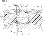
FIG. 3 , on a circumferential side surface of thecolumn portion 33 of theretainer 30, aflat surface portion 35 in which the side surfaces of theadjacent column portions 33 forming thepocket 34 are parallel to each other, and an outer diameter-side retaining portion 36 and an inner diameter-side retaining portion 37 respectively protruding from theflat surface portion 35 in the circumferential direction on an outer diameter side and an inner diameter side are formed. - The
flat surface portions 35 guide thecylindrical rollers 20 in the circumferential direction, and the outer diameter-side retaining portions 36 and the inner diameter-side retaining portions 37 prevent thecylindrical rollers 20 from falling out of thepockets 34. - A distance L between the
flat surface portions 35 ofadjacent column portions 33 is 101.5% to 107% (1.015D ≤ L ≤ 1.070D) of a roller diameter D, a circumferential protrusion amount S1 of the outer diameter-side retaining portion 36 from theflat surface portion 35 is 1% to 4% (0.01D ≤ S1 ≤ 0.04D) of the roller diameter D, and a circumferential protrusion amount S2 of the inner diameter-side retaining portion 37 from theflat surface portion 35 is set to 4% to 10% (0.04 ≤ S2 ≤ 0.10D) of the roller diameter D. The protrusion amount S1 of the outer diameter-side retaining portion 36 is smaller than the protrusion amount S2 of the inner diameter-side retaining portion 37 (S1 < S2). - Since an engagement margin between the outer diameter-
side retaining portion 36 and thecylindrical roller 20 is set to be small due to the circumferential protrusion amount S1, thecylindrical roller 20 can be easily assembled into theretainer 30 without damaging theretainer 30 even when thecylindrical roller 20 is pushed into thepocket 34 of theretainer 30 from the outer diameter side. Further, since theouter ring 11 is disposed on the outer diameter side of thecylindrical rollers 20 held by theretainer 30, thecylindrical rollers 20 do not fall off from the outer diameter side of thepockets 34 when the bearing is used. Therefore, the engagement margin on the outer diameter side can be set to be smaller than an engagement margin on the inner diameter side as long as, in an assembly process of the bearing, theretainer 30 into which thecylindrical rollers 20 are assembled can hold thecylindrical rollers 20 until theretainer 30 is inserted into theouter ring 11. - Further, since the engagement margin on the inner diameter side between the inner diameter-
side retaining portion 37 and thecylindrical roller 20 is set to be large due to the circumferential protrusion amount S2, thecylindrical rollers 20 can be prevented from falling off from the inner diameter side of thepocket 34 during transportation before assembly to the shaft or during an assembly process to the shaft. - The
flat surface portion 35 is provided in a radially intermediate portion of thepocket 34 including a position through which a pitch circle diameter PCD of eachcylindrical roller 20 passes. The outer diameter-side retaining portion 36 and the inner diameter-side retaining portion 37 are connected to theflat surface portion 35 byinclined surfaces inclined surface 38 and theflat surface portion 35 is set to be smaller than an angle θ2 formed by the inner diameter-sideinclined surface 39 and the flat surface portion 35 (θ1 < θ2), and is preferably set to be about 1/3 to 1/2 of the angle θ2 (θ2/3 ≤ θ1 ≤ θ2/2). - Further, in the
retainer 30 of the present embodiment, theannular portion 32 on the other side in the axial direction is provided with, at equal intervals in the circumferential direction, a plurality of (three in the present embodiment)protrusion portions 40 each having an engagingportion 41 protruding radially outward with respect to an inner circumferential surface of theinward flange portion 15. In this case, theprotrusion portion 40 is provided to extend toward the other side in the axial direction from an end surface on the other side in the axial direction of theannular portion 32. In the engagingportion 41, a portion having a triangular cross section which increase in thickness from the other side in the axial direction toward the one side in the axial direction has a predetermined circumferential length on an outer diameter side of theprotrusion portion 40. An outer circumferential surface of theannular portion 32 faces the inner circumferential surface of theinward flange portion 15 with a slight radial gap therebetween, and the end surface on the other side in the axial direction of theannular portion 32 is located on (protrudes toward) the other side in the axial direction with respect to a side surface on the other side in the axial direction of theinward flange portion 15. - Accordingly, when the
outer ring 11 is inserted into theretainer 30, in which thecylindrical rollers 20 are assembled, from the other side in the axial direction, the engagingportions 41 are pressed by the inner circumferential surface of theinward flange portion 15 and elastically deformed toward the inner diameter side, and thus theinward flange portion 15 climbs over the engagingportions 41. Then, theinward flange portion 15 is sandwiched at the outer circumferential surface of theannular portion 32 between axial end surfaces of thecylindrical rollers 20 and side surfaces on the one side in the axial direction of theprotrusion portions 40, and theretainer 30 does not fall off from theouter ring 11 even in the single bearing. In the related art, the cylindrical rollers are inserted from the inner side after the retainer is inserted into the outer ring, but in the present embodiment, theretainer 30 and thecylindrical rollers 20 can be combined in advance to form an intermediate assembly and then assembled to theouter ring 11, and the assemblability can be improved. - Further, the
outward flange portion 14 of theouter ring 11 is provided with aprojection portion 16, which further extends toward the outer diameter side, in a part thereof in the circumferential direction. As illustrated inFIG. 5 , thecylindrical roller bearing 10 with an outer ring is used by press-fitting the outer circumferential surface of thecylindrical portion 13 of theouter ring 11 into amating member 50, and theprojection portion 16 is fitted into arecess portion 51 of themating member 50, and thus a position of thecylindrical roller bearing 10 with an outer ring in the circumferential direction with respect to themating member 50 can be regulated, and creep can be prevented. In the present embodiment, theprojection portion 16 is provided at one position in the circumferential direction, but may be provided at two or more positions. - Further, as illustrated in
FIG. 6 , when an axial distance between a flat surface on the one side in the axial direction of theoutward flange portion 14 and an end surface on the one side in the axial direction of theannular portion 31 on the one side in the axial direction is set as A, and an axial distance between a flat surface on the other side in the axial direction of theinward flange portion 15 and a side surface on the one side in the axial direction of the engagingportion 41 is set as B, B is greater than A (B > A), and (A + 0.1 mm) ≤ B ≤ (A + 1.0 mm) is preferably satisfied. This condition is based on the premise that an axial center of thecylindrical roller 20 and an axial center of thepocket 34 coincide with each other. - Accordingly, when another
mating member 60 to be abutted against the flat surface on the one side in the axial direction of theoutward flange portion 14 of theouter ring 11 is provided on a lateral side of thecylindrical roller bearing 10 with an outer ring, theretainer 30 is moved to a left side in the drawing, and theannular portion 31 is abutted against themating member 60 before the engagingportions 41 are abutted against theinward flange portion 15. Therefore, the engagingportions 41 of theretainer 30 having a relatively low strength can be prevented from being damaged due to contact with or sliding with respect to theouter ring 11. - As described above, according to the
cylindrical roller bearing 10 with an outer ring of the present embodiment, since theannular portion 32 on the other side in the axial direction of theretainer 30 is provided with the plurality ofprotrusion portions 40 each having the engagingportion 41 protruding radially outward with respect to the inner circumferential surface of theinward flange portion 15, theinward flange portion 15 of theouter ring 11 is sandwiched between thecylindrical rollers 20 and theprotrusion portions 40, and theretainer 30 can be prevented from falling off from theouter ring 11 without increasing the number of components with good assembly workability. - Further, when the axial distance between the flat surface on the one side in the axial direction of the
outward flange portion 14 and the end surface on the one side in the axial direction of theannular portion 32 on the one side in the axial direction is set as A, and the axial distance between the flat surface on the other side in the axial direction of theinward flange portion 15 and the side surface on the one side in the axial direction of the engagingportion 41 is set as B, it is set that B is greater than A, so that the engagingportions 41 of theretainer 30 are less likely to come into contact with or slide with respect to theinward flange portion 15 of theouter ring 11, and the engagingportions 41 can be prevented from being damaged. - Further, on the side surface of the
column portion 33 of theretainer 30, the distance L between theflat surface portions 35 of theadjacent column portions 33 is 101.5% to 107% of the roller diameter D, the circumferential protrusion amount S1 of the outer diameter-side retaining portion 36 from theflat surface portion 35 is 1% to 4% of the roller diameter D, and the circumferential protrusion amount S2 of the inner diameter-side retaining portion 37 from theflat surface portion 35 is 4% to 10% of the roller diameter D, so that the insertion workability of thecylindrical rollers 20 and the prevention of thecylindrical rollers 20 from falling off from theretainer 30 can be realized. - Further, it is preferable that three or
more protrusion portions 40 are provided at equal intervals in the circumferential direction, and thus, as illustrated inFIG. 7 , even when theouter ring 11 is an elliptical shape (inFIG. 7 , a vertical axis passing through theprojection portion 16 is a short axis, and a horizontal axis is a long axis), theretainer 30 can be prevented from coming out of theouter ring 11. - As in a first modification illustrated in
FIG. 8 , theprotrusion portions 40 may be provided at two positions facing each other in the radial direction. In this case, even when theouter ring 11 is an elliptical shape, theouter ring 11 can be easily assembled into theretainer 30 from the axial direction by matching a phase of the long axis of theouter ring 11 having an elliptical shape with a phase in which theprotrusion portion 40 of theretainer 30 is provided. - Further, as illustrated in
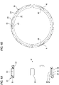
FIGS. 9A and 9B , by setting a total circumferential length occupied by theprotrusion portions 40 to 5% to 20% of an entire circumferential length of the axial end surface of theretainer 30, theretainer 30 can be easily assembled into theouter ring 11. When the total circumferential length of theprotrusion portions 40 is less than 5% of the entire circumferential length, the holding force is reduced, and when the total circumferential length exceeds 20% of the entire circumferential length, theprotrusion portions 40 increase in rigidity, which makes the assembly difficult. -
FIG. 9A illustrates a second modification in which the total circumferential length of theprotrusion portions 40 is 20% of the entire circumferential length of the axial end surface of theretainer 30.FIG. 9B illustrates a third modification in which the total circumferential length of theprotrusion portions 40 is 5% of the entire circumferential length of the axial end surface of theretainer 30. - The circumferential length described above is a length along the circumferential direction at a radial position of the outer circumferential surface of the
annular portion 32. - Further, the shape of the engaging
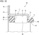
portion 41 may be a convex curved shape in cross section, that is, a substantially hemispherical shape as in a fourth modification illustrated inFIG. 10 . In the case of a substantially hemispherical shape, since theretainer 30 can be formed by axial drawing instead of radial drawing, cost reduction can be achieved. - Further, as in a fifth modification illustrated in
FIG. 11 , the shapes of the engagingportions 41 formed on the plurality ofprotrusion portions 40 on the circumference may not be the same. Further, the circumferential lengths of theprotrusion portions 40 may not be the same. - Next, a cylindrical roller bearing with an outer ring according to a second embodiment will be described with reference to
FIG. 12 . - In a
resin retainer 30a of the present embodiment, theprotrusion portion 40 provided on a side surface of theannular portion 32 is located in a region in which thecolumn portion 33 having high rigidity is disposed (in the same phase as the column portion 33) in the circumferential direction. - Specifically, the
protrusion portion 40 is formed at a phase (position) which is a center in the circumferential direction of thecolumn portion 33, and a circumferential length of theprotrusion portion 40 is smaller than a circumferential length of thecolumn portion 33. When the circumferential length of thecolumn portion 33 is small, the circumferential length of theprotrusion portion 40 may be equal to or greater than the circumferential length of thecolumn portion 33 in a state where a circumferential center position of the column portion and a circumferential center position of theprotrusion portion 40 coincide with each other. - Accordingly, when an intermediate assembly in which the
retainer 30a and thecylindrical rollers 20 are assembled in advance is assembled to the outer ring 11 (when theinward flange portion 15 of theouter ring 11 rides over theprotrusion portions 40 of theretainer 30a while theprotrusion portions 40 of theretainer 30a are elastically deformed), deformation of theretainer 30 can be restricted, and thecylindrical rollers 20 can be prevented from falling off from theretainer 30a. - In the first embodiment, since the
protrusion portions 40 are disposed at equal intervals in the circumferential direction, a circumferential position relationship (phase) between theprotrusion portions 40 and thecolumn portions 33 is any relationship depending on the number of rollers. On the other hand, in the present embodiment, in order to satisfy the circumferential position relationship between theprotrusion portions 40 and thecolumn portions 33, theprotrusion portions 40 are not necessarily disposed at equal intervals in the circumferential direction, but are preferably disposed at positions as close to each other as possible. - Other configurations and operations are the same as those of the
cylindrical roller bearing 10 with an outer ring of the first embodiment. - Next, a cylindrical roller bearing with an outer ring according to a third embodiment will be described with reference to
FIG. 13 . In aresin retainer 30b of the present embodiment, theprotrusion portion 40 provided on a side surface of theannular portion 32 is located in a region in which thepocket 34 are disposed (in the same phase as the pocket 34) in the circumferential direction, and slits 42 extending in the axial direction from theannular portion 32 are formed in thecolumn portions 33 on both sides in the circumferential direction of thepocket 34 at which theprotrusion portion 40 is located. Theslit 42 is formed in a circumferential center portion of thecolumn portion 33 up to an axial middle position. - Accordingly, when the
outer ring 11 is inserted from the axial direction into theretainer 30b in which thecylindrical rollers 20 are assembled, theprotrusion portions 40 of theretainer 30b are easily deformed, and the assemblability between theouter ring 11 and theretainer 30b can be improved. - Other configurations and operations are the same as those of the
cylindrical roller bearing 10 with an outer ring of the first embodiment. - Next, a cylindrical roller bearing with an outer ring according to a fourth embodiment will be described with reference to
FIG. 14 . - In the
cylindrical roller bearing 10 with an outer ring according to the present embodiment, aretainer 30c includes the pair ofannular portions column portions 33, and theprotrusion portions 40 as in the above-described embodiment, but theretainer 30c is made of iron. - In the
iron retainer 30c, after an intermediate assembly of thecylindrical rollers 20 and theretainer 30c is inserted into theouter ring 11, a portion extending in the axial direction from an end portion on the other side in the axial direction of theannular portion 32 on the other side in the axial direction of theretainer 30c is bent outward in the radial direction to form theprotrusion portions 40 having the engagingportions 41. - Similarly to the first embodiment, the
protrusion portions 40 are provided at three positions at equal intervals in the circumferential direction. - Other configurations and operations are the same as those of the
cylindrical roller bearing 10 with an outer ring of the first embodiment. - The present invention is not limited to the embodiments described above, and modifications, improvements, and the like can be made as appropriate.
- For example, in the first embodiment, an outer diameter of the
annular portion 32 corresponds to an inner diameter of theinward flange portion 15 and is smaller than an outer diameter of theannular portion 31. However, the outer diameter of theannular portion 32 may be set to be the same as the outer diameter of theannular portion 31 by reducing a radial dimension of theinward flange portion 15. Further, the outer diameters of the pair ofannular portions annular portion 31. - Further, the protrusion portion may be formed by providing, on both sides in the circumferential direction of the protrusion portion, a slit extending toward the one side in the axial direction from an end surface on the other side in the axial direction of the annular portion on the other side in the axial direction. In this case, the protrusion portion is formed in the annular portion on the other side in the axial direction without protruding from the end surface on the other side in the axial direction of the annular portion.
- The present application is based on the Japanese patent application (
Japanese Patent Application No. 2020-033342) filed on February 28, 2020 -
- 10: cylindrical roller bearing with outer ring
- 11: outer ring
- 12: outer ring raceway surface
- 14: outward flange portion
- 15: inward flange portion
- 16: projection portion
- 20: cylindrical roller
- 30: retainer
- 31, 32: annular portion
- 33: column portion
- 34: pocket
- 35: flat surface portion
- 36: outer diameter-side retaining portion
- 37: inner diameter-side retaining portion
- 38, 39: inclined surface
- 40: protrusion portion
- 41: engaging portion
Claims (7)
- A cylindrical roller bearing with an outer ring, comprising:an outer ring which includes:a cylindrical portion having an outer ring raceway surface on an inner circumferential surface thereof;an outward flange portion extending radially outward from an end portion on one side in an axial direction of the cylindrical portion; andan inward flange portion extending radially inward from an end portion on the other side in the axial direction of the cylindrical portion;a plurality of cylindrical rollers which are disposed rollably on the outer ring raceway surface; anda retainer which includes a pair of annular portions spaced apart in the axial direction, and a plurality of column portions connecting the pair of annular portions and arranged at intervals in a circumferential direction, and in which the plurality of cylindrical rollers are rollably held by a plurality of pockets each being formed by the column portions adjacent to each other and the pair of annular portions, wherein:the annular portion on the other side in the axial direction is provided with a plurality of protrusion portions each having an engaging portion protruding radially outward with respect to an inner circumferential surface of the inward flange portion; andwhen an axial distance between a flat surface on the one side in the axial direction of the outward flange portion and an end surface on the one side in the axial direction of the annular portion on the one side in the axial direction is set as A, and an axial distance between a flat surface on the other side in the axial direction of the inward flange portion and a side surface on the one side in the axial direction of the engaging portion is set as B, B is greater than A.
- The cylindrical roller bearing with an outer ring according to claim 1, wherein
when the retainer is viewed from the axial direction, a total circumferential length occupied by the protrusion portions is 5% to 20% of an entire circumferential length of the retainer. - The cylindrical roller bearing with an outer ring according to claim 1 or 2, wherein
the protrusion portion is located in a region in which the column portion is disposed in a circumferential direction. - The cylindrical roller bearing with an outer ring according to claim 1 or 2, wherein:the protrusion portion is located in a region in which the pocket is disposed in a circumferential direction; andslits extending in the axial direction from the annular portion are formed in the column portions on both sides of the pocket at which the protrusion portion is located.
- The cylindrical roller bearing with an outer ring according to any one of claims 1 to 4, wherein:on a side surface of the column portion, a flat surface portion in which the side surfaces of the adjacent column portions forming the pocket are parallel to each other, and an outer diameter-side retaining portion and an inner diameter-side retaining portion protruding from the flat surface portion in a circumferential direction on an outer diameter side and an inner diameter side are formed;a distance between the flat surface portions of the adjacent column portions is 101.5% to 107% of a roller diameter;a circumferential protrusion amount of the outer diameter-side retaining portion from the flat surface portion is 1% to 4% of the roller diameter; anda circumferential protrusion amount of the inner diameter-side retaining portion from the flat surface portion is 4% to 10% of the roller diameter.
- The cylindrical roller bearing with an outer ring according to any one of claims 1 to 5, wherein
the retainer is made of resin, and the engaging portion has a triangular cross section or a convex curved cross section. - The cylindrical roller bearing with an outer ring according to any one of claims 1 to 3, wherein
the retainer is made of metal, and the protrusion portion is formed by bending a portion axially extending from the end portion on the other side in the axial direction of the annular portion on the other side in the axial direction.
Applications Claiming Priority (2)
| Application Number | Priority Date | Filing Date | Title |
|---|---|---|---|
| JP2020033342A JP7472544B2 (en) | 2020-02-28 | 2020-02-28 | Cylindrical roller bearing with outer ring |
| PCT/JP2021/000534 WO2021171800A1 (en) | 2020-02-28 | 2021-01-08 | Cylindrical roller bearing with outer ring |
Publications (3)
| Publication Number | Publication Date |
|---|---|
| EP4112956A1 true EP4112956A1 (en) | 2023-01-04 |
| EP4112956A4 EP4112956A4 (en) | 2023-07-19 |
| EP4112956B1 EP4112956B1 (en) | 2024-10-23 |
Family
ID=77491371
Family Applications (1)
| Application Number | Title | Priority Date | Filing Date |
|---|---|---|---|
| EP21760364.6A Active EP4112956B1 (en) | 2020-02-28 | 2021-01-08 | Cylindrical roller bearing with outer ring |
Country Status (4)
| Country | Link |
|---|---|
| EP (1) | EP4112956B1 (en) |
| JP (1) | JP7472544B2 (en) |
| CN (1) | CN115190949B (en) |
| WO (1) | WO2021171800A1 (en) |
Families Citing this family (1)
| Publication number | Priority date | Publication date | Assignee | Title |
|---|---|---|---|---|
| CN115076226A (en) * | 2022-07-14 | 2022-09-20 | 苏州市东吴滚针轴承有限公司 | A stamped needle roller bearing with flange |
Family Cites Families (13)
| Publication number | Priority date | Publication date | Assignee | Title |
|---|---|---|---|---|
| US4907898A (en) * | 1989-01-03 | 1990-03-13 | The Torrington Company | Roller bearing with single flange races |
| DE3902194A1 (en) * | 1989-01-26 | 1990-08-02 | Schaeffler Waelzlager Kg | RADIAL ROLLER BEARING |
| JP2006242284A (en) * | 2005-03-03 | 2006-09-14 | Nsk Ltd | Cylindrical roller bearing with flange |
| JP2007056932A (en) * | 2005-08-23 | 2007-03-08 | Nsk Ltd | Shell needle roller bearing |
| JP2009052653A (en) * | 2007-08-27 | 2009-03-12 | Ntn Corp | Cylindrical roller bearing |
| JP5689603B2 (en) * | 2010-01-04 | 2015-03-25 | Ntn株式会社 | Support bearing |
| JP2013068281A (en) * | 2011-09-22 | 2013-04-18 | Ntn Corp | Roller bearing |
| DE102013225342A1 (en) * | 2013-12-10 | 2015-06-11 | Schaeffler Technologies AG & Co. KG | Cage for supporting rolling elements of a rolling bearing |
| DE102014203827A1 (en) * | 2014-03-03 | 2015-09-03 | Schaeffler Technologies AG & Co. KG | Easy to assemble rolling bearing |
| DE102014217168A1 (en) | 2014-08-28 | 2016-03-17 | Schaeffler Technologies AG & Co. KG | Needle bearing with a cage and a retaining lug formed on the cage |
| JP6911761B2 (en) * | 2015-09-18 | 2021-07-28 | 日本精工株式会社 | Manufacturing method of tapered roller bearings and tapered roller bearings |
| JP2018080718A (en) * | 2016-11-14 | 2018-05-24 | 日本精工株式会社 | Cylindrical roller bearing |
| KR20200023984A (en) | 2018-08-27 | 2020-03-06 | 삼성전자주식회사 | Heterocyclic compound and organic light emitting device including the same |
-
2020
- 2020-02-28 JP JP2020033342A patent/JP7472544B2/en active Active
-
2021
- 2021-01-08 EP EP21760364.6A patent/EP4112956B1/en active Active
- 2021-01-08 CN CN202180016841.XA patent/CN115190949B/en active Active
- 2021-01-08 WO PCT/JP2021/000534 patent/WO2021171800A1/en not_active Ceased
Also Published As
| Publication number | Publication date |
|---|---|
| EP4112956B1 (en) | 2024-10-23 |
| CN115190949B (en) | 2024-09-17 |
| EP4112956A4 (en) | 2023-07-19 |
| JP2021134890A (en) | 2021-09-13 |
| WO2021171800A1 (en) | 2021-09-02 |
| JP7472544B2 (en) | 2024-04-23 |
| CN115190949A (en) | 2022-10-14 |
Similar Documents
| Publication | Publication Date | Title |
|---|---|---|
| US20110116734A1 (en) | Punched retainer, self-aligning roller bearing, and method of manufacturing punched retainer | |
| US8899840B2 (en) | Tapered roller bearing | |
| US20160153494A1 (en) | Cage for a toroidal roller bearing | |
| EP3540251A1 (en) | Cylindrical roller bearing | |
| CN113167320A (en) | Tapered Roller Bearings | |
| EP2239473B1 (en) | Rolling bearing cage | |
| EP4112956B1 (en) | Cylindrical roller bearing with outer ring | |
| JP7485948B2 (en) | Cage for spherical roller bearing | |
| EP2963306B1 (en) | Preliminary holder for radial needle bearing | |
| EP3396184B1 (en) | Crossed roller bearing | |
| US8328430B2 (en) | Thrust roller bearing | |
| EP4116595A1 (en) | Cage and roller | |
| US9453534B2 (en) | Tapered roller bearing | |
| JP2001208054A (en) | Tapered roller bearing | |
| EP3040569B1 (en) | Method for manufacturing shell-type needle bearing, and manufacturing jig used in manufacture of same | |
| US20200362911A1 (en) | Roller and cage assembly and planetary gear support structure | |
| CN115962226A (en) | Cylindrical roller bearing | |
| JP2010025230A (en) | Pressed cage, self-aligning roller bearing, and manufacturing method for pressed cage | |
| JP2025174538A (en) | Tapered roller bearing cage and tapered roller bearing | |
| CN110325751B (en) | Cages and thrust roller bearings for thrust roller bearings | |
| JP2006194369A (en) | Self-aligning roller bearing cage, self-aligning roller bearing and manufacturing method thereof | |
| CN119384563A (en) | Cage for thrust roller bearing and thrust roller bearing | |
| CN116601398A (en) | Thrust Roller Bearings | |
| JP4853512B2 (en) | Thrust roller bearing | |
| JP2009293700A (en) | Cage for tapered roller bearing |
Legal Events
| Date | Code | Title | Description |
|---|---|---|---|
| STAA | Information on the status of an ep patent application or granted ep patent |
Free format text: STATUS: THE INTERNATIONAL PUBLICATION HAS BEEN MADE |
|
| PUAI | Public reference made under article 153(3) epc to a published international application that has entered the european phase |
Free format text: ORIGINAL CODE: 0009012 |
|
| STAA | Information on the status of an ep patent application or granted ep patent |
Free format text: STATUS: REQUEST FOR EXAMINATION WAS MADE |
|
| 17P | Request for examination filed |
Effective date: 20220826 |
|
| AK | Designated contracting states |
Kind code of ref document: A1 Designated state(s): AL AT BE BG CH CY CZ DE DK EE ES FI FR GB GR HR HU IE IS IT LI LT LU LV MC MK MT NL NO PL PT RO RS SE SI SK SM TR |
|
| DAV | Request for validation of the european patent (deleted) | ||
| DAX | Request for extension of the european patent (deleted) | ||
| A4 | Supplementary search report drawn up and despatched |
Effective date: 20230615 |
|
| RIC1 | Information provided on ipc code assigned before grant |
Ipc: F16C 19/46 20060101ALI20230609BHEP Ipc: F16C 33/54 20060101ALI20230609BHEP Ipc: F16C 33/56 20060101ALI20230609BHEP Ipc: F16C 33/46 20060101ALI20230609BHEP Ipc: F16C 19/26 20060101AFI20230609BHEP |
|
| GRAP | Despatch of communication of intention to grant a patent |
Free format text: ORIGINAL CODE: EPIDOSNIGR1 |
|
| STAA | Information on the status of an ep patent application or granted ep patent |
Free format text: STATUS: GRANT OF PATENT IS INTENDED |
|
| RIC1 | Information provided on ipc code assigned before grant |
Ipc: F16C 19/46 20060101ALI20240531BHEP Ipc: F16C 33/54 20060101ALI20240531BHEP Ipc: F16C 33/56 20060101ALI20240531BHEP Ipc: F16C 33/46 20060101ALI20240531BHEP Ipc: F16C 19/26 20060101AFI20240531BHEP |
|
| INTG | Intention to grant announced |
Effective date: 20240703 |
|
| GRAS | Grant fee paid |
Free format text: ORIGINAL CODE: EPIDOSNIGR3 |
|
| GRAA | (expected) grant |
Free format text: ORIGINAL CODE: 0009210 |
|
| STAA | Information on the status of an ep patent application or granted ep patent |
Free format text: STATUS: THE PATENT HAS BEEN GRANTED |
|
| AK | Designated contracting states |
Kind code of ref document: B1 Designated state(s): AL AT BE BG CH CY CZ DE DK EE ES FI FR GB GR HR HU IE IS IT LI LT LU LV MC MK MT NL NO PL PT RO RS SE SI SK SM TR |
|
| REG | Reference to a national code |
Ref country code: GB Ref legal event code: FG4D |
|
| REG | Reference to a national code |
Ref country code: CH Ref legal event code: EP |
|
| REG | Reference to a national code |
Ref country code: DE Ref legal event code: R096 Ref document number: 602021020693 Country of ref document: DE |
|
| REG | Reference to a national code |
Ref country code: IE Ref legal event code: FG4D |
|
| REG | Reference to a national code |
Ref country code: LT Ref legal event code: MG9D |
|
| REG | Reference to a national code |
Ref country code: NL Ref legal event code: MP Effective date: 20241023 |
|
| REG | Reference to a national code |
Ref country code: AT Ref legal event code: MK05 Ref document number: 1735055 Country of ref document: AT Kind code of ref document: T Effective date: 20241023 |
|
| PG25 | Lapsed in a contracting state [announced via postgrant information from national office to epo] |
Ref country code: NL Free format text: LAPSE BECAUSE OF FAILURE TO SUBMIT A TRANSLATION OF THE DESCRIPTION OR TO PAY THE FEE WITHIN THE PRESCRIBED TIME-LIMIT Effective date: 20241023 |
|
| PG25 | Lapsed in a contracting state [announced via postgrant information from national office to epo] |
Ref country code: NL Free format text: LAPSE BECAUSE OF FAILURE TO SUBMIT A TRANSLATION OF THE DESCRIPTION OR TO PAY THE FEE WITHIN THE PRESCRIBED TIME-LIMIT Effective date: 20241023 |
|
| PG25 | Lapsed in a contracting state [announced via postgrant information from national office to epo] |
Ref country code: IS Free format text: LAPSE BECAUSE OF FAILURE TO SUBMIT A TRANSLATION OF THE DESCRIPTION OR TO PAY THE FEE WITHIN THE PRESCRIBED TIME-LIMIT Effective date: 20250223 Ref country code: PT Free format text: LAPSE BECAUSE OF FAILURE TO SUBMIT A TRANSLATION OF THE DESCRIPTION OR TO PAY THE FEE WITHIN THE PRESCRIBED TIME-LIMIT Effective date: 20250224 Ref country code: HR Free format text: LAPSE BECAUSE OF FAILURE TO SUBMIT A TRANSLATION OF THE DESCRIPTION OR TO PAY THE FEE WITHIN THE PRESCRIBED TIME-LIMIT Effective date: 20241023 |
|
| PG25 | Lapsed in a contracting state [announced via postgrant information from national office to epo] |
Ref country code: FI Free format text: LAPSE BECAUSE OF FAILURE TO SUBMIT A TRANSLATION OF THE DESCRIPTION OR TO PAY THE FEE WITHIN THE PRESCRIBED TIME-LIMIT Effective date: 20241023 |
|
| PG25 | Lapsed in a contracting state [announced via postgrant information from national office to epo] |
Ref country code: BG Free format text: LAPSE BECAUSE OF FAILURE TO SUBMIT A TRANSLATION OF THE DESCRIPTION OR TO PAY THE FEE WITHIN THE PRESCRIBED TIME-LIMIT Effective date: 20241023 |
|
| PG25 | Lapsed in a contracting state [announced via postgrant information from national office to epo] |
Ref country code: ES Free format text: LAPSE BECAUSE OF FAILURE TO SUBMIT A TRANSLATION OF THE DESCRIPTION OR TO PAY THE FEE WITHIN THE PRESCRIBED TIME-LIMIT Effective date: 20241023 |
|
| PG25 | Lapsed in a contracting state [announced via postgrant information from national office to epo] |
Ref country code: NO Free format text: LAPSE BECAUSE OF FAILURE TO SUBMIT A TRANSLATION OF THE DESCRIPTION OR TO PAY THE FEE WITHIN THE PRESCRIBED TIME-LIMIT Effective date: 20250123 |
|
| PG25 | Lapsed in a contracting state [announced via postgrant information from national office to epo] |
Ref country code: AT Free format text: LAPSE BECAUSE OF FAILURE TO SUBMIT A TRANSLATION OF THE DESCRIPTION OR TO PAY THE FEE WITHIN THE PRESCRIBED TIME-LIMIT Effective date: 20241023 Ref country code: LV Free format text: LAPSE BECAUSE OF FAILURE TO SUBMIT A TRANSLATION OF THE DESCRIPTION OR TO PAY THE FEE WITHIN THE PRESCRIBED TIME-LIMIT Effective date: 20241023 Ref country code: GR Free format text: LAPSE BECAUSE OF FAILURE TO SUBMIT A TRANSLATION OF THE DESCRIPTION OR TO PAY THE FEE WITHIN THE PRESCRIBED TIME-LIMIT Effective date: 20250124 |
|
| PG25 | Lapsed in a contracting state [announced via postgrant information from national office to epo] |
Ref country code: PL Free format text: LAPSE BECAUSE OF FAILURE TO SUBMIT A TRANSLATION OF THE DESCRIPTION OR TO PAY THE FEE WITHIN THE PRESCRIBED TIME-LIMIT Effective date: 20241023 |
|
| PG25 | Lapsed in a contracting state [announced via postgrant information from national office to epo] |
Ref country code: RS Free format text: LAPSE BECAUSE OF FAILURE TO SUBMIT A TRANSLATION OF THE DESCRIPTION OR TO PAY THE FEE WITHIN THE PRESCRIBED TIME-LIMIT Effective date: 20250123 |
|
| PG25 | Lapsed in a contracting state [announced via postgrant information from national office to epo] |
Ref country code: SM Free format text: LAPSE BECAUSE OF FAILURE TO SUBMIT A TRANSLATION OF THE DESCRIPTION OR TO PAY THE FEE WITHIN THE PRESCRIBED TIME-LIMIT Effective date: 20241023 |
|
| PG25 | Lapsed in a contracting state [announced via postgrant information from national office to epo] |
Ref country code: DK Free format text: LAPSE BECAUSE OF FAILURE TO SUBMIT A TRANSLATION OF THE DESCRIPTION OR TO PAY THE FEE WITHIN THE PRESCRIBED TIME-LIMIT Effective date: 20241023 |
|
| PG25 | Lapsed in a contracting state [announced via postgrant information from national office to epo] |
Ref country code: EE Free format text: LAPSE BECAUSE OF FAILURE TO SUBMIT A TRANSLATION OF THE DESCRIPTION OR TO PAY THE FEE WITHIN THE PRESCRIBED TIME-LIMIT Effective date: 20241023 |
|
| PG25 | Lapsed in a contracting state [announced via postgrant information from national office to epo] |
Ref country code: RO Free format text: LAPSE BECAUSE OF FAILURE TO SUBMIT A TRANSLATION OF THE DESCRIPTION OR TO PAY THE FEE WITHIN THE PRESCRIBED TIME-LIMIT Effective date: 20241023 |
|
| REG | Reference to a national code |
Ref country code: DE Ref legal event code: R097 Ref document number: 602021020693 Country of ref document: DE |
|
| PG25 | Lapsed in a contracting state [announced via postgrant information from national office to epo] |
Ref country code: SK Free format text: LAPSE BECAUSE OF FAILURE TO SUBMIT A TRANSLATION OF THE DESCRIPTION OR TO PAY THE FEE WITHIN THE PRESCRIBED TIME-LIMIT Effective date: 20241023 |
|
| PG25 | Lapsed in a contracting state [announced via postgrant information from national office to epo] |
Ref country code: CZ Free format text: LAPSE BECAUSE OF FAILURE TO SUBMIT A TRANSLATION OF THE DESCRIPTION OR TO PAY THE FEE WITHIN THE PRESCRIBED TIME-LIMIT Effective date: 20241023 |
|
| PG25 | Lapsed in a contracting state [announced via postgrant information from national office to epo] |
Ref country code: IT Free format text: LAPSE BECAUSE OF FAILURE TO SUBMIT A TRANSLATION OF THE DESCRIPTION OR TO PAY THE FEE WITHIN THE PRESCRIBED TIME-LIMIT Effective date: 20241023 |
|
| REG | Reference to a national code |
Ref country code: DE Ref legal event code: R119 Ref document number: 602021020693 Country of ref document: DE |
|
| PLBE | No opposition filed within time limit |
Free format text: ORIGINAL CODE: 0009261 |
|
| REG | Reference to a national code |
Ref country code: CH Ref legal event code: PL |
|
| STAA | Information on the status of an ep patent application or granted ep patent |
Free format text: STATUS: NO OPPOSITION FILED WITHIN TIME LIMIT |
|
| PG25 | Lapsed in a contracting state [announced via postgrant information from national office to epo] |
Ref country code: SE Free format text: LAPSE BECAUSE OF FAILURE TO SUBMIT A TRANSLATION OF THE DESCRIPTION OR TO PAY THE FEE WITHIN THE PRESCRIBED TIME-LIMIT Effective date: 20241023 |
|
| PG25 | Lapsed in a contracting state [announced via postgrant information from national office to epo] |
Ref country code: MC Free format text: LAPSE BECAUSE OF FAILURE TO SUBMIT A TRANSLATION OF THE DESCRIPTION OR TO PAY THE FEE WITHIN THE PRESCRIBED TIME-LIMIT Effective date: 20241023 Ref country code: LU Free format text: LAPSE BECAUSE OF NON-PAYMENT OF DUE FEES Effective date: 20250108 |
|
| GBPC | Gb: european patent ceased through non-payment of renewal fee |
Effective date: 20250123 |
|
| 26N | No opposition filed |
Effective date: 20250724 |
|
| PG25 | Lapsed in a contracting state [announced via postgrant information from national office to epo] |
Ref country code: DE Free format text: LAPSE BECAUSE OF NON-PAYMENT OF DUE FEES Effective date: 20250801 |
|
| PG25 | Lapsed in a contracting state [announced via postgrant information from national office to epo] |
Ref country code: GB Free format text: LAPSE BECAUSE OF NON-PAYMENT OF DUE FEES Effective date: 20250123 Ref country code: BE Free format text: LAPSE BECAUSE OF NON-PAYMENT OF DUE FEES Effective date: 20250131 |
|
| PG25 | Lapsed in a contracting state [announced via postgrant information from national office to epo] |
Ref country code: FR Free format text: LAPSE BECAUSE OF NON-PAYMENT OF DUE FEES Effective date: 20250131 |
|
| PG25 | Lapsed in a contracting state [announced via postgrant information from national office to epo] |
Ref country code: CH Free format text: LAPSE BECAUSE OF NON-PAYMENT OF DUE FEES Effective date: 20250131 |
|
| REG | Reference to a national code |
Ref country code: BE Ref legal event code: MM Effective date: 20250131 |
|
| PG25 | Lapsed in a contracting state [announced via postgrant information from national office to epo] |
Ref country code: IE Free format text: LAPSE BECAUSE OF NON-PAYMENT OF DUE FEES Effective date: 20250108 |